EP4335700A1 - Basisanordnung einer aussenrückblickvorrichtung, aussenrückblickvorrichtung und fahrzeug - Google Patents
Basisanordnung einer aussenrückblickvorrichtung, aussenrückblickvorrichtung und fahrzeug Download PDFInfo
- Publication number
- EP4335700A1 EP4335700A1 EP23195587.3A EP23195587A EP4335700A1 EP 4335700 A1 EP4335700 A1 EP 4335700A1 EP 23195587 A EP23195587 A EP 23195587A EP 4335700 A1 EP4335700 A1 EP 4335700A1
- Authority
- EP
- European Patent Office
- Prior art keywords
- camera
- base
- assembly
- base cover
- cover
- Prior art date
- Legal status (The legal status is an assumption and is not a legal conclusion. Google has not performed a legal analysis and makes no representation as to the accuracy of the status listed.)
- Pending
Links
- 238000004140 cleaning Methods 0.000 claims abstract description 33
- 239000012530 fluid Substances 0.000 claims abstract description 13
- 239000011521 glass Substances 0.000 claims description 26
- 230000004313 glare Effects 0.000 claims description 23
- 238000011109 contamination Methods 0.000 claims description 7
- 238000007789 sealing Methods 0.000 description 90
- 238000000034 method Methods 0.000 description 17
- 239000000758 substrate Substances 0.000 description 13
- 230000014759 maintenance of location Effects 0.000 description 12
- 230000002093 peripheral effect Effects 0.000 description 7
- 229910052782 aluminium Inorganic materials 0.000 description 5
- XAGFODPZIPBFFR-UHFFFAOYSA-N aluminium Chemical compound [Al] XAGFODPZIPBFFR-UHFFFAOYSA-N 0.000 description 5
- 229910052751 metal Inorganic materials 0.000 description 3
- 239000002184 metal Substances 0.000 description 3
- 230000008569 process Effects 0.000 description 3
- 239000007787 solid Substances 0.000 description 3
- 150000001875 compounds Chemical class 0.000 description 2
- 239000000463 material Substances 0.000 description 2
- 230000036316 preload Effects 0.000 description 2
- 238000006748 scratching Methods 0.000 description 2
- 230000002393 scratching effect Effects 0.000 description 2
- VYZAMTAEIAYCRO-UHFFFAOYSA-N Chromium Chemical compound [Cr] VYZAMTAEIAYCRO-UHFFFAOYSA-N 0.000 description 1
- 230000004913 activation Effects 0.000 description 1
- AZDRQVAHHNSJOQ-UHFFFAOYSA-N alumane Chemical class [AlH3] AZDRQVAHHNSJOQ-UHFFFAOYSA-N 0.000 description 1
- 230000000712 assembly Effects 0.000 description 1
- 238000000429 assembly Methods 0.000 description 1
- 238000005452 bending Methods 0.000 description 1
- 230000000295 complement effect Effects 0.000 description 1
- 108010038204 cytoplasmic linker protein 190 Proteins 0.000 description 1
- 230000007246 mechanism Effects 0.000 description 1
- 230000004048 modification Effects 0.000 description 1
- 238000012986 modification Methods 0.000 description 1
- 238000000465 moulding Methods 0.000 description 1
- 230000004224 protection Effects 0.000 description 1
- 230000008439 repair process Effects 0.000 description 1
- 230000000284 resting effect Effects 0.000 description 1
- 230000007704 transition Effects 0.000 description 1
- XLYOFNOQVPJJNP-UHFFFAOYSA-N water Substances O XLYOFNOQVPJJNP-UHFFFAOYSA-N 0.000 description 1
Images


Classifications
-
- B—PERFORMING OPERATIONS; TRANSPORTING
- B60—VEHICLES IN GENERAL
- B60R—VEHICLES, VEHICLE FITTINGS, OR VEHICLE PARTS, NOT OTHERWISE PROVIDED FOR
- B60R11/00—Arrangements for holding or mounting articles, not otherwise provided for
- B60R11/04—Mounting of cameras operative during drive; Arrangement of controls thereof relative to the vehicle
-
- B—PERFORMING OPERATIONS; TRANSPORTING
- B60—VEHICLES IN GENERAL
- B60R—VEHICLES, VEHICLE FITTINGS, OR VEHICLE PARTS, NOT OTHERWISE PROVIDED FOR
- B60R1/00—Optical viewing arrangements; Real-time viewing arrangements for drivers or passengers using optical image capturing systems, e.g. cameras or video systems specially adapted for use in or on vehicles
- B60R1/02—Rear-view mirror arrangements
- B60R1/06—Rear-view mirror arrangements mounted on vehicle exterior
-
- B—PERFORMING OPERATIONS; TRANSPORTING
- B60—VEHICLES IN GENERAL
- B60R—VEHICLES, VEHICLE FITTINGS, OR VEHICLE PARTS, NOT OTHERWISE PROVIDED FOR
- B60R1/00—Optical viewing arrangements; Real-time viewing arrangements for drivers or passengers using optical image capturing systems, e.g. cameras or video systems specially adapted for use in or on vehicles
- B60R1/12—Mirror assemblies combined with other articles, e.g. clocks
-
- B—PERFORMING OPERATIONS; TRANSPORTING
- B60—VEHICLES IN GENERAL
- B60R—VEHICLES, VEHICLE FITTINGS, OR VEHICLE PARTS, NOT OTHERWISE PROVIDED FOR
- B60R1/00—Optical viewing arrangements; Real-time viewing arrangements for drivers or passengers using optical image capturing systems, e.g. cameras or video systems specially adapted for use in or on vehicles
- B60R1/02—Rear-view mirror arrangements
- B60R1/06—Rear-view mirror arrangements mounted on vehicle exterior
- B60R1/0602—Rear-view mirror arrangements mounted on vehicle exterior comprising means for cleaning or deicing
-
- B—PERFORMING OPERATIONS; TRANSPORTING
- B60—VEHICLES IN GENERAL
- B60R—VEHICLES, VEHICLE FITTINGS, OR VEHICLE PARTS, NOT OTHERWISE PROVIDED FOR
- B60R1/00—Optical viewing arrangements; Real-time viewing arrangements for drivers or passengers using optical image capturing systems, e.g. cameras or video systems specially adapted for use in or on vehicles
- B60R1/12—Mirror assemblies combined with other articles, e.g. clocks
- B60R2001/1253—Mirror assemblies combined with other articles, e.g. clocks with cameras, video cameras or video screens
-
- B—PERFORMING OPERATIONS; TRANSPORTING
- B60—VEHICLES IN GENERAL
- B60R—VEHICLES, VEHICLE FITTINGS, OR VEHICLE PARTS, NOT OTHERWISE PROVIDED FOR
- B60R11/00—Arrangements for holding or mounting articles, not otherwise provided for
- B60R2011/0001—Arrangements for holding or mounting articles, not otherwise provided for characterised by position
- B60R2011/004—Arrangements for holding or mounting articles, not otherwise provided for characterised by position outside the vehicle
Definitions
- the present disclosure refers to a base assembly of an exterior rear view device to be mounted to a vehicle, a rear view device with a head assembly and such a base assembly, a vehicle with such a rear view device and a method for assembling as well as dis-assembling such a rear view device.
- a rear view device typically includes a base assembly to be attached to a vehicle and a head assembly to be moveable relative to the base assembly.
- the head assembly of a rear view device can be rotated between a driving position and a parking position.
- the term "rear view” may refer to a view of the surrounding area, which is not in the field of view of a driver of a vehicle, i.e. the directions opposing, left, right, below and above of the viewing direction, but can also comprise the view in the direction of the viewing direction of the driver and/or any combinations of the directions.
- the rear view can be achieved via at least one rear view element in form of a reflective element like a mirror and/or an image acquisition means like a camera.
- the rear view, that is the field of view of the driver can be adjusted by moving, in particular rotating, the reflective element and/or the image acquisition means. This in turn can be realized by moving the complete head assembly together with the reflective element and/or the image acquisition means such that the head assembly of the rear view device can be rotated also between a plurality of viewing position.
- an actuator assembly is comprised by the rear view device, which can be controlled by a first control unit within the vehicle. Also the image acquisition means can be controlled via a second control unit, wherein both control units may be formed together. However, for the purpose of controlling data have to be transferred between the rear view device and the control unit within the vehicle requiring a harness.
- US 2020/0001791 A1 refers to a base assembly of an exterior rear view device, comprising a base frame; and a base cover housing the base frame and formed in at least two parts connected to each other, wherein the base assembly comprises a first opening at a first end of the base assembly at which the base frame is configured to be attached to a vehicle and a second opening at a second end of the base assembly at which a head assembly of the exterior rear view device is configured to be attached to the base frame, wherein at least one of a first sealing means at the first opening is provided comprising a two-component gasket with a hard component and a soft component, the hard component comprising: at least one first connection element configured to engage at least one first connection element of a first cover part; and at least one first connection element of a second cover part configured to provide a locking connection between the first cover part and the second cover part, and/or a second sealing means at the second opening
- the base frame fulfills a multitude of functions, in particular that of supporting the head assembly and connecting the same as well as electronic components of the exterior rear view device to the vehicle and a central control unit within the vehicle, respectively, with the latter attachment requiring a harness to be safely guided and sealed, electrically as well as with respect to moisture.
- the base frame is made of metal, often aluminum, fulfilling said functions is a challenge.
- the base frame is covered by one or more pieces to achieve a pleasing appearance and to adapt the exterior rear view device to the vehicle design. Further, the cover pieces have to fulfill technical functions, like water drainage and the like.
- DE 10 2018 116 008 A1 discloses a base assembly of an exterior rear view device, comprising a base frame; and a base cover housing the base frame and formed in at least two parts connected to each other, wherein the base assembly comprises a first opening at a first end of the base assembly at which the base frame is configured to be attached to a vehicle and a second opening at a second end of the base assembly at which a head assembly of the exterior rear view device is configured to be attached to the base frame, wherein at least one of a first sealing means at the first opening is provided comprising a two-component gasket with a hard component and a soft component, the hard component comprising: at least one first connection element configured to engage at least one first connection element of a first cover part; and at least one first connection element of a second cover part configured to provide a locking connection between the first cover part and the second cover part, and/or a second sealing means at the second opening is comprising a two-component gasket with a hard component and a soft component, the hard component
- US 2015/0224930 A1 relates to an exterior rearview mirror assembly configured for mounting at an exterior portion of a vehicle, said exterior rearview mirror assembly comprising: a mounting arm configured for attachment at an exterior portion of a vehicle equipped with said exterior rearview mirror assembly; a mirror head attached at said mounting arm; an attaching element attached at a mirror reflective element; a shroud extending from said attaching element and partially received in said mirror head; a mirror actuator operable to adjust said attaching element and said mirror reflective element relative to said mirror head, wherein said mirror actuator adjusts said mirror reflective element, said attaching element and said shroud in tandem relative to said mirror head; and wherein said mirror reflective element is disposed outside of said mirror head and said shroud spans a gap between said mirror reflective element and said mirror head to substantially encase said attaching element.
- US 2017/0253184 A1 discloses a vehicle side-view mirror comprising: a mirror base, which is fixed to a vehicle body; and a mirror head, which includes a mirror surface, is attached to the mirror base to be rotatable about an axis vertically extending with respect to the mirror base, and is switchable between a folded position and an operative position, wherein a gap is formed between the mirror base and the mirror head, a sleeve, which protrudes upward, is formed on the mirror base, an opening, into which the sleeve is inserted, is formed in a bottom of the mirror head, the sleeve has an outer peripheral surface on which a first outer peripheral surface and a second outer peripheral surface, which is located further in an inward radial direction of the sleeve than the first outer peripheral surface, are formed in a circumferential direction, the second outer peripheral surface is formed so as to extend smoothly in the circumferential direction of the sleeve, and a passage, which guides wind entering the gap into
- a base cover of a base assembly of an exterior rear view device to be mounted to a vehicle and to moveably support a head assembly comprises three cover pieces designed to releasably mantle the base frame via clip, snap and/or latch connections, in particular without screw connections.
- Embodiments of the base cover can be further defined in that the three cover pieces comprise a lower base cover, a base cover cap and an upper base cover and/or are made from plastic, and/or the three cover pieces isolate the base frame being made from a metal; and/or the three cover pieces cover an arm of the base frame from a door attachment portion to a head attachment portion of the base frame, and/or the three cover pieces are connected by clip, snap and/or latch connections, with said connections preferably being provided between the three cover pieces, or the three cover pieces and a sealing means adapted to be arranged between the door and the base frame, or the three cover pieces and the base frame, or the three cover pieces, the sealing means and the base frame to provide the base assembly.
- the lower base cover is provided with an opening for a camera attached to the base frame, in particular via a camera cradle, and/or a drain hole
- the lower base cover is provided with one or more first attachment means, in particular five clips and a multi-functional assembly projection, for attachment to the base frame
- the lower base cover is provided with one or more second attachment means, in particular comprising three hooks, for attachment to the sealing means, in particular a door gasket substrate of the sealing means
- the lower base cover has an edge to engage the sealing means, in particular a door seal gasket of the sealing means and/or for an outer sealing
- the lower base cover is provided with one or more third attachment means for attachment to the base cover cap, in particular comprising the multi-functional assembly projection and openings
- the lower base cover is provided with one or more fourth attachment means for attachment to the upper base cover, in particular comprising a pocket and openings.
- the base cover cap may be provided with an opening for a camera attached to the base frame, in particular via a camera cradle; and/or the base cover cap may be provided with one or more fifth attachment means for attachment to the lower base cover, in particular comprising peg like projections and a tab; and/or the base cover cap may be provided with one or more sixth attachment means for attachment to the upper base cover, in particular comprising peg like projections, a slot and two clips, preferably in form of two leaf spring clips adapted to rest on the base frame at the root and end, allowing the middle portion there between to flex downwards; and/or the base cover cap is provided with one or more seventh attachment means for attachment to the base frame, in particular comprising at least one clip.
- embodiments may be defined in that the upper base cover is provided with an opening for a camera attached to the base frame, in particular via a camera cradle; and/or the upper base cover is provided with one or more eighth attachment means for attachment to the lower base cover, in particular comprising location pegs and/or at least one clip; the base cover cap is provided with one or more ninth attachment means for attachment to with the base cover cap, in particular comprising clip retention extensions and at least one alignment projection, and/or the upper base cover is provided with one or more tenth attachment means, in particular a hoop clip, for engagement with the sealing element, in particular a projection of the door gasket substrate.
- Embodiments may also be characterized by a glare shield surrounding a lens of a camera, in particular the lens extending through the opening of the base cover cap, and providing an opening through which the camera can obtain images, wherein preferably the glare shield is configured to be releasably attached to at least one of the three cover pieces and/or a camera cradle of the camera via at least one the via clip, snap and/or latch connection. It may be that the glare shield is provided with at least one clip, wherein preferably the at least one clip of the glare shield is configured to at least one of engaging the base cover cap or at least one extension or lug of the base cover cap and being supported by the camera cradle or at last one retention tab of the camera cradle.
- an exterior rearview device which comprises a base assembly with a base frame to be attached to a vehicle, a head assembly for supporting at least one reflective element, display element and/or camera, with the head assembly being attached to the base assembly in a moveable manner, and a sealing means adapted to be installed between the base assembly and a door of the vehicle, wherein the base frame is manteled with a base cover according to the present disclosure.
- Said exterior rear view device may further comprise at least one camera, preferably positioned in a non-moving area of the moveable head assembly or in the base assembly, in particular attached to the base frame and/or viewing through an opening provided by one of three cover pieces, and/or a camera cradle which is configured to be attached to the base frame, in particular by a friction fit and without any separable attachment element, with the camera cradle preferably being a plastic unit for isolating the camera from the base frame; and/or a retainer means between the base frame and the sealing means, with the retainer means preferably being a plastic unit for sealing and guiding harness.
- the exterior rear view device may comprise an articulation assembly for moving the head assembly relative to the base assembly, and/or at least one functional device, comprising a light module, a turn signal indicator module, a blind spot indicator module, or a human machine interface, a Bluetooth module, a sensor module, a temperature sensor, a touch sensor or a contamination sensor, and a cleaning device for cleaning the lens, in particular comprising at least one fluid port or nozzle, and/or a control unit, in particular adapted for controlling at least one of the display element, the articulation assembly and the functional device.
- a functional device comprising a light module, a turn signal indicator module, a blind spot indicator module, or a human machine interface, a Bluetooth module, a sensor module, a temperature sensor, a touch sensor or a contamination sensor, and a cleaning device for cleaning the lens, in particular comprising at least one fluid port or nozzle, and/or a control unit, in particular adapted for controlling at least one of the display element, the articulation assembly and the functional device.
- the display element is configured to be at least one of viewable through the reflective element when activated and activated by at least one of a driver of the vehicle, depending on an output signal of the sensor module, via a vehicle control system and/or via the control unit.
- a vehicle with the door having a door panel and supporting a window as well as a cheater channel sealed by glass run seal is provided, wherein the door panel also supports the exterior rear view device of the present disclosure.
- the glass run seal is arranged within a channel provided by the base frame with the retainer means and the sealing means; and/or a lip of the glass run seal engages the cheater panel and the upper base cover; and/or the glass run seal is at least partly covered by a waist finisher such that the base assembly extends from the waist finisher.
- the same provides a method for assembling the base cover of the present disclosure, wherein the base cover cap, the lower base cover and the base cover cap are connected by snap, clips and/or latch connections to each other and the base frame, without screws, and the assembly of the base cover cap, the lower base cover and the upper base cover on the base frame is secured by engaging the sealing means.
- Said assembling method may further comprise the following steps: comprising the following steps attaching the lower base cover to the sealing means and the base frame, wherein preferably an edge of the lower base cover is brought into engagement with the door gasket seal such that the lower base cover can be rotated until it connects with the base frame and its opening is arranged to allow the camera to view out of the cover, with in particular the hooks the lower base cover being rotated into hook pockets and/or between ribs provided by the door gasket substrate.
- the assembling method may comprise the following step: attaching the base cover cap to the lower base cover, wherein preferably the base cover cap is attached at one end to the lower base cover for creating a rotation point to rotate the base cover cap into its final position with attachment also at its other end, with in particular the tab at the end of the base cover cap, which faces the door attachment portion of the base frame, being entered into the opening of the lower base cover for defining the attachment direction and locks in behind the lower base cover for creating a rotation point, and/or with in particular the base cover cap being forced to flex outboard while being rotated into its final position, and/or with in particular the peg type projection at the end of the base cover cap, which faces the head attachment portion of the base frame, being entered into a first slot in the multi-functional assembly projection of the lower base cover and another peg type projection of the base cover cap being entered into another slot in the multi-functional assembly projection of the lower base cover as well as flexes back into the opening of the lower base cover for controlling the final fit of the base cover
- said assembling method may comprise the following steps: attaching the upper base cover to the base cover cap and the lower base cover, wherein preferably the attachment of the upper base cover is assisted by the base cover cap being assembled to the base frame by providing a ramp guiding a rotational movement of the upper base cover with in particular the upper base cover being attached at one end to the lower base cover and the base cover cap for creating a rotation point to rotate upper base cover into its final position with attachment also at its other end, and/or with in particular the two location pegs at the end of the upper base cover, which faces the head attachment portion of the base frame, being fitted into two corresponding slots, one being provided by the opening in lower base cover and the other by the slot being formed in the projection of the base cover cap , and/or with in particular the outermost location peg pulling the base cover cap into its final position and defining a rotation axis; and/or with in particular rotating the upper base cover until the four location projections position the upper base cover on the lower base cover, and/or with in particular the ramp is provided by the
- the following step may be comprised: connecting the glare shield for the camera, preferably by pushing the same between the base cover cap and the cradle of said camera, with in particular pushing the at least one clip in engagement with the at least one extension or lug of the base cover cap and the at last one retention tab of the camera cradle, and/or with in particular the connecting step of the glare shield being the last step of assembling the base cover.
- the same provides a method for dis-assembling the base cover of the present disclosure, in particular after assembling the base cover with a method of the present disclosure, wherein the base cover cap, the lower base cover and the base cover cap are dis-mantled with a single tool by dis-lodging the snap, clips and/or latch connections and/or with the base frame being mounted to the vehicle.
- the dis-assembling method can be further defined in that the tool is a metal piece, preferably made out of aluminum, and/or the tool has a maximum diameter of 4 mm, preferably is in form of a cylinder or pin; and/or the tool locks the mirror head assembly in a knock forward position to gain access to a camera connector and/or the camera when the base cover cap, the lower base cover and the base cover cap have been dis-mantled from the base frame; and/or the tool dis-engages at least one of the snap, clips and/or latch connections.
- the tool is a metal piece, preferably made out of aluminum, and/or the tool has a maximum diameter of 4 mm, preferably is in form of a cylinder or pin; and/or the tool locks the mirror head assembly in a knock forward position to gain access to a camera connector and/or the camera when the base cover cap, the lower base cover and the base cover cap have been dis-mantled from the base frame; and/or the tool dis-engages at least one of the snap, clips and/or
- said dis-assembling method may comprise the following steps, when the base cover has been assembled with the method of the present disclosure: accessing the hoop clip of the upper base cover through a slot in door panel to loosen the engagement with the projection of the door gasket substrate, and/or passing through the drain hole of the lower base cover to loosen the engagement of the clip of the upper base cover with the pocket of the lower base cover, and/or removing the upper base cover by pulling its clip retention extensions out of the two clips of the base cover cap , and/or dis-mounting the base cover cap by dis-engaging its clip from the location projection of the base frame, preferably by using the tool, and its peg projections from the multi-functional assembly projection of the lower base cover, preferably by pushing them out of position, such that the base cover cap can rotate out, and/or dis-engaging the five clips of the lower base cover from the base frame such that the lower base cover can be removed.
- the dis-assembling method can also comprise the following step: locking the mirror head assembly in the knock forward position by inserting the tool into a recess or hole of the base frame to access a mechanical stop of a case frame of the head assembly from the bottom of the base assembly; wherein preferably all parts the tool interfaces with are made from aluminum.
- the following step may be comprised: the glare shield is dis-mantled, preferably with the tool, by dis-lodging the snap, clips and/or latch connections, with in particular the dis-mantling of the glare shield being the first dis-mantling step.
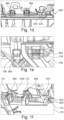
- Figures 1a to 1f show a base cover lower or lower base cover 170 and a base frame 110 of a base assembly 100 of a first exterior rear view device 1 of the present disclosure
- the exterior rear view device 1 is adapted to be mounted to a vehicle 2 as shown in particular in figure 9b .
- figures 1c and 1d show a sealing means 800.
- the sealing means 800 is to be attached to both, the lower base cover 170 and the base frame 110 and to be arranged between the base assembly 100 and the vehicle 2.
- the lower base cover 170 of figure 1a is a single plastic piece with a multi-functional assembly projection 171, several hooks 172 to 174, several clips 175 to 179, a pocket 160, several openings 161, 162, 164 and 165 and a wall 163. Further, the lower base cover 170 provides an opening 702 for a camera 700, see figure 6b , and a drain hole 166.
- the base frame 110 of figure 1b is provided in form of an aluminum unit with a plurality of clips 102 to 107 and three hook apertures 108, 109 and 118.
- the unit can be divided into three portions, i.e. a door attachment portion 115, an arm 116 and a head attachment portion 117, with the door attachment portion 115 running substantially parallelly to a door 600 of the vehicle 1 shown in figures 9a and 9b , whereas the arm 116 extends substantially perpendicularly away from the door attachment portion 115 and the head attachment portion 117 is provided at the end of the arm 116 opposite the one merging with the door attachment portion 115.
- the sealing means 800 of figure 1c is provided in form of a 2K door gasket with a door gasket seal 802 and a door gasket substrate 804.
- the door gasket substrate 804 is formed with several clips 840 (only one being shown in figure 1c ), two hook pockets 860 and 862, two location ribs 870 and 872 and one attachment projection 866 discussed in detail below.
- Figures 1d and 1e demonstrate the attachment of the lower base cover 170 of figure 1a , being one of three cover pieces of the base frame 110, to the base frame 110 shown in figure 1b .
- the combination of the base frame 110, the sealing means 800 and the lower base cover 170 is shown in figure 1f providing a locking system without the need of screws and accommodating a location as well as assembly method.
- the lower base cover assembly method allows a secure mounting of the components without using screws, as
- the hook pockets 860 and 862 are door gasket location features with multiple functions. They provide location and positional control whilst assembling the sealing means 800 to the base frame 110, with the hook pockets 860 and 862 of the sealing means 800 passing through the hook apertures 108 and 109 of the base frame 110 as soon as the sealing means 800 is attached to the base frame 110, see figure 1e .
- the hook pockets 860 and 862 are used to assemble the lower base cover 170.
- the hooks 173 and 174 of the lower base cover 170 are engaged within the hook pockets 860 and 862 of the sealing means 800. Further the third hook 172 of the lower base cover 170 is located between the two ribs 870 and 872 of the sealing means 800.
- the hook pockets 860 and 862 and the ribs 870 and 872 of the sealing means 800 lock and locate the door gasket seal in all X + Y + Z directions. Critically the Z direction is locked which allows an accurate positional location for the sealing strategy.
- the retainer means 301 may be manufactured from a plastic material and it provides a retainer assembly 300, together with the sealing means 800, to be arranged between the base frame 110 of the base assembly 100 of the exterior rear view device 1 and the door panel 605 of the door 600 of the vehicle 2.
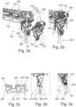
- the figures 2a to 2e also show a harness 400 for electrically connecting in particular a power source and a control unit within the vehicle (not shown) with electric components of the exterior rear view device.
- electric components may comprise, as e.g. shown in figures 4a to 4f , an actuator assembly 210 suitable for moving a head assembly 200 together with a reflective element (not shown) relative to the base frame 110 supporting the head assembly 200, and a camera 700 as well as an indicator means like a turn signal indicator 710 shown in particular in figure 9b .
- Said harness 400 may comprise a camera harness 410.
- the retainer means 301 is a multi-function component. The different functions will be described with respect to the other components of the exterior rear view device 1 as well as the vehicle 2 in the following.
- An important function of the retainer means 301 is harness sealing, managing harness routing and accommodating variation in the camera harness 410 and cleaning systems (not shown), as described in the following.
- the door attachment portion 115 of the base frame 110 is provided with an opening 124 for a harness holder 500 at its lower, free end, as best seen in figures 2d and 2e .
- Said harness holder 500 is formed with a fixing tie 510 for holding the harness 400 and a clip 520 for connecting the holder 500 to said door attachment portion 115 by passing through the opening 124.
- the base frame harness locator opening feature governs harness position length the door side and the rear view device side, and provides a strong retention eliminating risk of the harness 400 being misplaced e.g. by being pulled through during handling. Further, the locating feature leads to reduced tolerance of fit-to-door.
- the harness 400 is firmly located to the base frame 110 in all directions allowing a solid datum strategy for harness lengths and provides the ability to hold as well as transport the exterior rear view device 1 whilst holding on to the harness 400.
- the harness 400 as well as the camera harness 410 divided therefrom above the harness holder 500 extend between the door attachment portion 115 of the base frame 110 and a holding portion 320 of the retainer means 301 to an upper end of the door attachment portion 115, which turns into the arm 116 of the base frame 110.
- the retainer means 301 is provided with guiding means for guiding the camera harness 410 to a sealing portion 310 of the retainer means 301 extending substantially perpendicularly to the holding portion 320 to cover the camera harness 410 at its bending region at the transition between the door attachment portion 115 and the arm 116, see region A in figure 2b .
- the holding portion 320 of the retainer means 301 also provides a camera harness guiding channel portion 340 to substantially close a channel 420 for the camera harness 410, as shown in figure 2c .
- the sealing of the harness 400, together with the camera harness 410, as well as the attachment of the metallic base frame 110 to the door panel 605 becomes safer.
- the design of the retainer means 301 allows to accommodate different sets of harness and cleaning system for all variations of mirror trim level. Further, the retainer means 301 ensures an easy assembly to seal in particular the camera harness 410 after being mounted and to manage its routing along the base frame door attachment portion 115, without departing from the commonly used datum system between the base frame 110 and the door panel 605.
- the base frame 110 is provided with a location pin 120 as well as a T shaped location projection 121 belonging to the datum system ensuring a correct assembly of the components of the exterior rear view device 1 and a correct attachment of the exterior rear view device 1 to the vehicle 2.
- the location pin 120 and the T shaped location projection 121 extend substantially perpendicularly to the plane of the door panel 605, as can be best seen in figures 3a and 3d .
- the retainer means 301 is provided with an opening 322 for the location pin 120 and a hook 350 with openings 351 for the arms of T shaped location projection 121, as can be best seen in figure 3b.
- Figure 3d illustrates that the location pin 120 as well as the T shaped location projection 121 pass through the respective openings 322, 351 of the retainer means 301 to also pass respective openings 610, 620 within the door panel 605 to engage the same, with the hook 350 of the retainer means 301 ensuring the respective engagement.
- the base frame T shaped location projection 121 and the location pin 120 provide the primary and secondary datum strategy to the door datum system in X + Z directions, while the Y direction is controlled by using screws.
- the door panel 605 in figure 3d shows two screw openings 631 and 632 aligned to two screw openings 131 and 132 of the base frame 110, respectively, which in turn pass openings 371 and 372 of the retainer means 301.
- the corresponding locating features of the base frame 110 and the retainer means 301 allow the base frame datum features to interface with the door 600 minimizing tolerance of datum strategy.
- the retainer means 301 along with the location pin 120 and the T shaped location projection 121 not only provides an accurate assembly to the door panel datum system, but also facilitates the assembly as it provides a robust 3rd hand clip/hanger function.
- the retainer means 301 provides a first clip 315, which serves the attachment to the base frame 110 as best seen in figures 2a and 2b .
- the hook 350 primarily serves to hold the exterior rear view device 1 in Y direction to assist assembly of the screws (not shown), while the second clip 360 is on secondary location keyway to highlight when the exterior rear view device 1 is in its final assembly Z position, as best seen in figure 3d .
- the slim design of the base frame 110 allows the lower case 220 of the head assembly 200 to be assembled over the door attachment portion 115 and the arm 116 of the base frame 110 to reach the region of the head assembly 200 with the actuator assembly 210, as shown in figures 4a to 4d .
- the lower case 220 is provided with an opening 222, preferably being substantially circular, through which the base frame 110 together with the retainer means 301 can pass.
- the sealing means 800 is mounted after the lower case 220, as shown in figures 4e and 4f .
- the sealing means location strategy is critical as it dictates the datum strategy for the corresponding base cover components.
- sealing means 800 permit the lower case 220 to be assembled over the base frame 110.
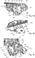
- the attachment of the sealing means 800 to the base frame 110 with the retainer means 301 is described with reference to figures 5a to 5c .
- Clips 810, 830 and 840 as well as clip opening 820 allow to attach the sealing means 800 to the base frame 110 which is provided with complementary steps 135 and 136 and openings 137 and 138.
- the base frame 110 also is provided with the location projections 125 to 126, with two of said location projections 125 and 125 extending through the retainer means 301 as well as the sealing means 800 attached on top of the retainer means 301, see figure 5a .
- Figure 5b also shows a clip 316 of the retainer means 301 engaging a respective opening 137 provided by the base frame 110.
- the sealing means 800 provides a datum area 850 for an upper base cover 190 as described with respect to figure 13i , with T-slots 391, 851 built into both the retainer means 301 and the sealing means 800, see figure 5c , to maximize and gain strength from the base frame into the area for upper base cover assembly.
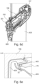
- the assembly process of the lower base cover 170 to the sub-assembly of figure 4f is designed in such a way that the camera hole 702 in the lower base cover 170 avoids scratching or fowling the camera lens whilst rotating into final assembled condition, by first approaching the lower base cover 170 to the base frame 110 ( figure 6a ), then attaching the lower base cover 170 to the base frame 110 at the door attachments portion 115 ( figure 6b ), and finally rotating the lower base cover 170 on the arm 116 ( figure 6c ).
- FIG. 6d The sub-assembly of the base frame 110, the retainer means 301, the sealing means 800 and the lower base cover 170 is shown in figure 6d , attached to the door panel 605.
- Figure 6e shows a cross-section taken along the line A-A in figure 6d . From figure 6e the functions of the sealing means 800 as a 2K door gasket, including an integrated 2-way simultaneous sealing function as well as providing datum, location and positional controls for matching the lower base cover 170, can be best seen.
- the 2-way simultaneous sealing is achieved due to the more or less S shape cross-sectional geometry of the door gasket seal 802, which may be a rubber part formed together with the door gasket substrate 802, to allow sealing in three areas with only one cavity in a 2K tool.
- the three sealing areas are marked with I, II and III in figure 6d :
- the sealing means geometry between the exterior rear view device 1 and vehicle door 600 provides a tolerant and accurate sealing strategy when considering the assembly direction.
- the tolerance between door panel 605 and door datum system may be large as sealing lip of the door gasket seal 802 of the sealing means 800 accommodates for such variations
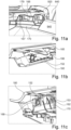
- FIG. 6d The sub-assembly shown in figure 6d is also shown in figure 7a , whereas figures 7b and 7c show details of the rotational attachment of the lower base cover 170, referred to above with respect to figures 6a to 6c :
- the rotational attachment of the lower base cover 170 ensures that the camera, in particular its lens, remains untouched by the lower base cover 170.
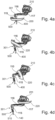
- FIGs 8a to 8c illustrate a camera cradle 704 for assembling in the base frame 110 for holding the camera 700 securely within the base assembly 100 of the exterior rear view device 1.
- the camera 700 is installed in the base frame 110 using the camera cradle 704, as shown in figure 8a .
- the camera cradle 704 is symmetrical along at least one axis and no screws are needed to attach the camera cradle 704 to the base frame 110. Further the body of the camera 700 is protected from contacting the metallic base frame 110 as the camera cradle 740 is made out of a plastic material in order to isolate the camera housing.
- the camera cradle 704 as shown in figure 8c is a one-piece element which is preferably formed by a molding process.
- the camera cradle 704 include one or more location ribs 742 inside the interior surface of the cradle 704 which hold the camera 700 securely in place to provide an accurate and tuneable positioning of the camera along the X, Y, and Z axes.
- the location ribs 742 include six ribs formed as two pairs of ribs on three interior walls of the camera cradle 704; however, any number of ribs 742 may be used.
- the camera cradle 704 also includes one or more anti-backout projections 746 and one or more clips 744.
- the anti-backout projections 746 are frictionally fit into the walls of the base frame 110 when the cradle 740 is inserted. When the walls of the base frame 110 push against the projections 746 and the cradle 704 is inserted, this also "locks" the clips 744 to tighten the attachment of the camera 700 to the camera cradle 704.
- anti-backout projections 746 and two clips 744 which are formed closer to a bottom edge of the cradle 704, i.e. the edge of the cradle 704 closer to the camera lens.
- any number of anti-backout projections 746 and clips 744 may be used in a variety of different positions. This ensures a tight lock of the camera 700 and stops the camera body from contacting the base frame 110.
- FIG 9a shows further details of the vehicle 2 in the region of the door 600, namely a cheater panel 640 as well as a window 1000, with a glass run seal 920 as well as a waist finisher 940.
- FIG 9b the final rear view device 1 attached to the vehicle 2 can be seen. Accordingly, the exterior rear view device 1 holds the glass run seal 920 in a solid position and, thereby, provides a very pleasing overall appearance suggesting that the exterior rear view device 1 extends or rather grows out of the waist finisher 940 covering a part of the glass run seal 920.
- figures 11a to 11e illustrate its attachment step by step, by starting in figure 11a with a part view of the sub-assembly of figure 7a attached to the door panel in order to be arranged next to the glass run seal 920, and showing attachment features of the base cover cap 180 in figure 1 1b .
- the base cover cap 180 is provided with a tab 152 in addition to the clips 184 to 186.
- the tab 152 of the base cover cap 180 is to be entered into an opening 168 of the lower base cover 170 provided on one side of the clip 179, shown in figure 1a .
- Said tab 152 defines the attachment direction and locks in behind the lower base cover 170, as illustrated in figure 11c , for creating said rotation point.
- the next step is to rotate the base cover cap 180 into final position.
- the rotation has been created such that no surrounding parts are scratched, by the outboard area of the base cover cap 180 being forced to flex outboard while rotating, as indicated in figure 11d .
- Figure 11e shows the peg type projection 150 of the base cover cap 180 entering into a slot in the multi-functional assembly projection 171 of the lower base cover 170, while the other peg type projection 153 of the base cover cap 180 enters into another slot in the multi-functional assembly projection 171 of the lower base cover 170 as well as flexing back into the opening 161 of the lower base cover 170 for controlling the final fit of the base cover cap 180.
- the sub-assembly of the base frame 110, the retainer means 301 and the sealing means 800 shown in figure 7a also forms a channel 900, see figures 12a and 12b , for positioning as well as locating the glass run seal 920 in particular allocated to the cheater panel 640 as shown e.g. in figure 12c .
- the combination the base frame 110, the retainer means 301 and the sealing means 800 forms the channel 900 which locates the glass run seal 920 on to the exterior rear view device 1.
- the glass run seal 920 runs along the cheater panel 640 and is an extension of the glass run seal running along the window 1000 and being covered by the waist finisher 940 as shown in figures 9b , 12c and 12d .
- the base cover cap 180 clips to the base frame 110, see figure 12d , and also the upper base cover 190, providing the last and third cover piece of the base frame 110, is attached by clip connection, see Figure 12e .
- the clip connection may be located behind a chrome waist finisher (not shown) and will be described below with respect to figures 13a to 13i .
- the cheater panel 640 pushes the glass run seal 920 into the correct position inside the channel 900 while being assembled.
- the base cover 180 and the upper base cover 190 assemble in such a way that when rotating into their position a sealing lip 922 of the glass run seal 920 is pushed against the cheater panel 640 sealing the gap between the base cover cap 180 and the upper base cover 190 on the one side and the cheater panel 640 on the other side, see figure 12f .
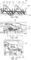
- Figures 13a to 13i illustrate details of the attachment of the upper base cover 190 with the lower base cover 170 and the base cover cap 180 to assemble the cover of the base frame 110.
- figure 13a shows the different attachment features of the upper base cover 190 with four location projections 192 to 195, a clip 198, a hoop clip 199, two location pegs 691, 692, two clip retention extensions 694 and 695 as well as three aligns projections 696 to 698.
- the two location pegs 691 and 692 need to be fitted into two corresponding slots, one being provided by the opening 162 in lower base cover 170 and the other by a slot 151 being formed in the projection 150 of the base cover cap 180, see figure 13c .
- the peg 691 pulls the base cover cap 180 into the final position and defines the rotation axis for the components. Rotating the components results in engagement of the four location projections 192 to 194 and 198 to position the upper base cover 190, see figures 13d to 13f .
- Three alignment features are provided by the upper base cover 190 in form of the projections 696 to 698 to align and lead two clip retention features in form of the clip retention extensions 694 and 695 onto the corresponding clips 185 and 186 of the base cover cap 180, see figure 13g .
- the bottom clip 198 of the upper base cover 190 goes into the pocket 160 in the lower base cover 170 and locates the bottom parts of the components 190 and 170, as shown in figure 13h .
- the last cover engagement feature is the hoop clip 199 of the upper base cover 190 which is shown in figure 13i and secures the whole assembly by engaging the projection 866 of the door gasket substrate 804.
- the sealing means 800 plays a central role due to in particular
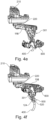
- Figures 14a to 14c demonstrate the attachment of the upper base cover 190 assisted by the base cover cap 180 while being assembled to the base frame 110 by providing a ramp guiding the rotational movement of the upper base cover 190.
- the ramp is provided by the two clips 185 and 186 the base cover cap 180 which also fulfill location and clips functions, simultaneously. Said clips 185 and 186 are arranged closer to the door attachment portion 115 of the base frame 110 than the third clip 184.
- the base cover cap leaf spring clips 185 and 186 rest on the base frame 110 at the root and end of each clip 185 and 186, allowing the middle portion of each clip 185 and 186 to flex downwards.
- Such a downward flex of the leaf spring clips 185 and 186 allows the upper base cover 190 to assemble and clip into position by rotating in the direction of the arrow B in figure 14b .
- the leaf spring interface with the upper base cover 190 allows pre load and tolerant fit of the three cover pieces 170, 180 and 190.
- the head assembly 200 To gain access to a camera connector 705 at the end of the camera harness 410, the head assembly 200 must be set into a knock forward position and locked into place so two hands can be used to remove the camera 700 and its connector 705, with figures 15c and 15b demonstrating the rotation of the head assembly 200 into said knock forward position, and details of the camera connector access is shown in the enlarged illustrations of figures 15e and 15f of parts of figures 15c and 15d , respectively.
- the tool 2000 with a maximum diameter of 4 mm may be used to lock the base frame 110 relative to the head assembly 200.
- the recess or hole 111 is designed into the base frame 110, which provides easy access to a mechanical stop 216 of a case frame 215 from the bottom of the base assembly 100, after removing the three cover pieces 170, 180 and 190.
- All parts the tool 2000 interfaces with are made from aluminum for maximal strength and security. Also the tool 2000 itself may be made out of aluminum.
- the three cover pieces of the present disclosure namely the lower base cover 170, the base cover cap 180 and the upper base cover 190 are designed
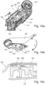
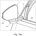
- Figures 18a and 18b depict a second external rear view device 1' of the present disclosure. It comprises a base assembly 100' onto which a moveable head assembly 200' is attached, i.e. at a head attachment portion 117' shown in figures 18c and 18d .
- the base assembly 100' is configured to be mounted to a vehicle at a door attachment portion 115' as described with respect to the first embodiment.
- the head assembly 200' comprises a reflective element 250' in form of an at least partly translucent mirror glass and a display element 260' integrated in the head assembly 200' by being arranged behind the at least partly translucent mirror glass in the view direction of a drive as indicated by the arrow A in figure 18b .
- This allows to present to a driver of a vehicle, to which the external rear view device 1' is attached, a rear view either by reflections on the at least partly translucent mirror glass as indicated by the arrows B in figure 18b or on the display element 260'.
- the base assembly 100' comprises a camera 700'.
- the display element 260' may be activated to present a rear view obtained by the camera 700'. Such an activation may be achieved by the driver for example by pressing a button on a dashboard, via a voice command, by a gesture or the like and/or depending on the output of a sensor (not shown).
- a sensor may be connected to a control unit 280' for controlling the display element 260' and maybe also an articulation assembly 210' for moving the head assembly 200'.
- Said control unit 280' may be arranged within the head assembly 200' as shown in figure 18b , but may also be arranged within the vehicle.
- a sensor signal characteristic for contamination of a lens 720' of the camera 700' may be used to switch off the display unit 260', whereas another sensor signal characteristic for high traffic situations and/or high speed may be used to switch on the display element 260', but many alternatives are within the teaching of the present disclosure.
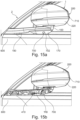
- the camera unit 700' is arranged in the base assembly 100' such that the lens 720' may obtain a rear view image through an opening 702' provided by the base assembly 100', see figure 18c .
- the camera 700' may be attached to a base frame 110', via a camera cradle 704', as best seen in figure 18e , and the opening 702' may be provided by cover pieces of the base frame 110'.
- Said cover pieces may comprise three pieces as described with respect to the first embodiment with respect to the figures 1 to 17c , namely a base cover cap 180', a lower base cover 170' and an upper base cover 190'.
- Said three base covers 170', 180' and 190' releaseably mantle the base frame 110' by being attached via clip, snap and/or latch connections.
- cover of the base frame 110' may comprise a glare shield 750', which is described in further detail with respect to figures 18c to 18e .
- the glare shield 750' is provided with two clips 750'a, 750'b to be attached to the base cover cap 180' as well as to the camera cradle 704', which serves to attach the camera 700' to the base frame 110'.
- This attachment may be the last assembly step on a customer line by sliding the glare shield 750' along the arrow C as indicated in figure 18c .
- FIG 18d shows the assembled glare shield 750' and details thereof can be seen in the cross-section taken along line A-A in figure 18e . Accordingly, each clip 750'a, 750'b or the like of the glare shield 750' engages the base cover cap 180', in particular an extension, lug 180'a or the like thereof. The free end of the clip 750'b is shown in figure 18e to be holed by a retention tab 704'a of the camera cradle 704'. This arrangement allows to maintain a small tolerance stack between the different components, with integrity of the glare shield 750' being protected. Further, serviceability is facilitated by this arrangement.
- Figure 18e also shows that an outer-rim 730' of the camera unit 700' extends beyond the camera cradle 704' as well as the base cap cover 180', but is shielded by the glare shield 750'.
- the rim 730' encompasses the lens 720'.
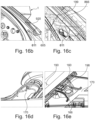
- Figure 19a shows such a further alternative in form of a base assembling 100" of a third rear view device of the present disclosure making usage of a base assembly 100" equipped with two cameras 700", 700′′′, which may be arranged substantially perpendicular to each other and an axis of a head attachment portion 117".
- a first camera 700" may extend through an opening 702" in a base cover cap 180" with its lens 720" as described with respect to figures 18a to 18e .
- a glare shield as described above may be attached.
- a second camera 700′′′ may be arranged such that its lens 720′′′ extends through an opening 702" in the lower base cover 170"'.
- a cleaning system may be associated with the second camera 700"', which may comprise a nozzle 760′′′ attached to and/or extending through the lower base cover 170′′′.
- the cleaning system may be controlled by a control unit in dependency of the output of a sensor sensing contamination. For example, the cleaning system may be activated when the sensor's output indicates that there is contamination on the lens.
- Figure 19b shows another view of the base assembling 100" of a third rear view device of the present disclosure making usage of a base assembly 100".
- the first camera 700" is arranged such that it is protected by a glare shield 750'.
- the second camera 700′′′ is arranged next to the cleaning system that comprises a cleaning nozzle such that the second camera may be cleaned by a cleaning fluid dispensed by cleaning nozzle 760′′′ .
- Figures 19c and 19d show the cleaning nozzle 760′′′, the second camera 700′′′ and the lens of the second camera 720′′′, and a cradle 704" These figures show that cradle 704" holds both the second camera 700′′′ and cleaning nozzle 760′′′.
- the cradle is attached to the lower base cover 170".
- the cradle 704" may be a plastic unit that is provided for isolating the second camera 700′′′ from the base frame.
- the cradle 704" may be configured to be attached to the base frame by a friction fit and without any separable attachment element.
- FIGS 19c and 19d are a cleaning fluid conduit 780′′′ that delivers cleaning fluid to the cleaning nozzle. Additionally, these figures show a cable 770′′′ that is connected to the second camera 700′′′. Cable 770′′′ may, for example, provide power and/or a data exchange to the second camera.
- the cleaning fluid conduit 780′′′ and the cable 770′′′ may both extend between the base frame and the base cover, and may be at least partly substantially parallel to each other.
- the embodiment shown in Figures 19a-19d may be connected to an exterior rearview device of a vehicle.
- the exterior rear view device may include a head assembly for supporting at least one of: a reflective element, a display element, and a third camera.
- the head assembly may be attached to the base assembly in a moveable manner.
- the external rear view device may further comprise at least one of an articulation assembly for moving the head assembly relative to the base assembly, and at least one functional device, comprising a light module, a turn signal indicator module, a blind spot indicator module, or a human machine interface, a Bluetooth module, a sensor module, a temperature sensor, a touch sensor or a contamination sensor, and a control unit.
- the control unit may particularly be adapted for controlling at least one of the cleaning system, the first camera, the second camera, the display element, the articulation assembly and the functional device.
- the display element of the external rearview device is configured to be at least one of, viewable through the reflective element when activated, activated by at least one of a driver of the vehicle depending on an output signal of the sensor module, via a vehicle control system and via the control unit and displaying images obtained from at least one of the first camera, the second camera and the third camera.
- a vehicle with a door having a door panel and supporting a window as well as a cheater panel sealed by a glass run seal may include a door panel that supports the exterior rearview device described herein.
Applications Claiming Priority (1)
| Application Number | Priority Date | Filing Date | Title |
|---|---|---|---|
| US17/939,247 US20230017426A1 (en) | 2021-03-25 | 2022-09-07 | 3 piece base cover, rear view device, vehicle and assembling and dis-assembling method |
Publications (1)
| Publication Number | Publication Date |
|---|---|
| EP4335700A1 true EP4335700A1 (de) | 2024-03-13 |
Family
ID=87934038
Family Applications (1)
| Application Number | Title | Priority Date | Filing Date |
|---|---|---|---|
| EP23195587.3A Pending EP4335700A1 (de) | 2022-09-07 | 2023-09-06 | Basisanordnung einer aussenrückblickvorrichtung, aussenrückblickvorrichtung und fahrzeug |
Country Status (1)
| Country | Link |
|---|---|
| EP (1) | EP4335700A1 (de) |
Citations (9)
| Publication number | Priority date | Publication date | Assignee | Title |
|---|---|---|---|---|
| US20150224930A1 (en) | 2014-02-12 | 2015-08-13 | Magna Mirrors Of America, Inc. | Exterior rearview mirror assembly |
| US20170253184A1 (en) | 2016-03-03 | 2017-09-07 | Ishizaki Honten Co., Ltd. | Vehicle side-view mirror |
| WO2018215599A1 (en) | 2017-05-24 | 2018-11-29 | Smr Patents Sarl | Pivot joint system and rear view device therewith |
| WO2019002627A1 (en) | 2017-06-30 | 2019-01-03 | Smr Patents Sarl | REARVIEW DEVICE COMPRISING A MOBILE HEAD ASSEMBLY AND VEHICLE HAVING THE SAME |
| US20200001791A1 (en) | 2018-07-02 | 2020-01-02 | Motherson Innovations Company Limited | Base assembly and rear view device therewith |
| US10899278B2 (en) * | 2017-11-15 | 2021-01-26 | Kabushiki Kaisha Tokai-Rika-Denki-Seisakusho | Vehicular visual recognition device |
| EP3798715A1 (de) * | 2019-09-30 | 2021-03-31 | Valeo Systèmes d'Essuyage | Sensormodul für ein fahrzeug mit mindestens einem sensor |
| US20220176880A1 (en) * | 2012-01-24 | 2022-06-09 | SMR Patents S.à.r.l. | External rearview device, external rearview device kit and vehicle |
| US20220191369A1 (en) * | 2019-03-22 | 2022-06-16 | Kabushiki Kaisha Tokai-Rika-Denki-Seisakusho | Vehicle camera device |
-
2023
- 2023-09-06 EP EP23195587.3A patent/EP4335700A1/de active Pending
Patent Citations (10)
| Publication number | Priority date | Publication date | Assignee | Title |
|---|---|---|---|---|
| US20220176880A1 (en) * | 2012-01-24 | 2022-06-09 | SMR Patents S.à.r.l. | External rearview device, external rearview device kit and vehicle |
| US20150224930A1 (en) | 2014-02-12 | 2015-08-13 | Magna Mirrors Of America, Inc. | Exterior rearview mirror assembly |
| US20170253184A1 (en) | 2016-03-03 | 2017-09-07 | Ishizaki Honten Co., Ltd. | Vehicle side-view mirror |
| WO2018215599A1 (en) | 2017-05-24 | 2018-11-29 | Smr Patents Sarl | Pivot joint system and rear view device therewith |
| WO2019002627A1 (en) | 2017-06-30 | 2019-01-03 | Smr Patents Sarl | REARVIEW DEVICE COMPRISING A MOBILE HEAD ASSEMBLY AND VEHICLE HAVING THE SAME |
| US10899278B2 (en) * | 2017-11-15 | 2021-01-26 | Kabushiki Kaisha Tokai-Rika-Denki-Seisakusho | Vehicular visual recognition device |
| US20200001791A1 (en) | 2018-07-02 | 2020-01-02 | Motherson Innovations Company Limited | Base assembly and rear view device therewith |
| DE102018116008A1 (de) | 2018-07-02 | 2020-01-02 | Motherson Innovations Company Limited | Basisanordnung mit Rückblickvorrichtung |
| US20220191369A1 (en) * | 2019-03-22 | 2022-06-16 | Kabushiki Kaisha Tokai-Rika-Denki-Seisakusho | Vehicle camera device |
| EP3798715A1 (de) * | 2019-09-30 | 2021-03-31 | Valeo Systèmes d'Essuyage | Sensormodul für ein fahrzeug mit mindestens einem sensor |
Similar Documents
| Publication | Publication Date | Title |
|---|---|---|
| US20230017426A1 (en) | 3 piece base cover, rear view device, vehicle and assembling and dis-assembling method | |
| EP1640215B1 (de) | Aussenrückspielgelanordnung für fahrzeug, die zur abstützung einer bilderfassungsvorrichtung ausgeführt ist | |
| US11597321B2 (en) | Exterior rearview mirror assembly | |
| US11285887B2 (en) | Module and support structure assembly | |
| US10589725B2 (en) | Window-wiper spray nozzle for a vehicle | |
| US20040184172A1 (en) | Rearview mirror assembly for motor vehicles | |
| EP4063194A1 (de) | Basisanordnung, rückblickvorrichtung und fahrzeug | |
| JP6536597B2 (ja) | 車室内前部構造 | |
| EP4335700A1 (de) | Basisanordnung einer aussenrückblickvorrichtung, aussenrückblickvorrichtung und fahrzeug | |
| EP4063152B1 (de) | 2k-türdichtung, rückblickvorrichtung, fahrzeug sowie verfahren zur montage und befestigung | |
| US6227500B1 (en) | Meter mounting structure and meter mounting method | |
| JP4263658B2 (ja) | ヘッドアップディスプレイ装置及びこれに用いられるミラーユニット | |
| JP2005145445A (ja) | 自動車用ウィンドウシェード | |
| JP4184070B2 (ja) | ランプユニットの取付構造 | |
| WO2022200470A1 (en) | 3 piece base cover, rear view device, vehicle and assembling and dis-assembling method | |
| EP3533655B1 (de) | Head-up-anzeigevorrichtung | |
| CN117098692A (zh) | 三件式基座盖、后视设备、车辆以及组装和拆卸方法 | |
| EP4074546A2 (de) | Multifunktionelle rückhaltemittel, verfahren zur montage einer rückblickvorrichtung und fahrzeug | |
| JP2018151632A (ja) | ヘッドアップディスプレイ装置 | |
| JP4116807B2 (ja) | 車両用サイドミラー及び車両用サイドミラーの製造方法 | |
| CN211308413U (zh) | 行车记录仪安装结构和车辆 | |
| JP5344679B2 (ja) | カウルトップカバー | |
| JP3891385B2 (ja) | カップホルダの構造 | |
| CN114830477B (zh) | 两部件式电气壳体 | |
| JP2003165332A (ja) | 車両用サンバイザー |
Legal Events
| Date | Code | Title | Description |
|---|---|---|---|
| PUAI | Public reference made under article 153(3) epc to a published international application that has entered the european phase |
Free format text: ORIGINAL CODE: 0009012 |
|
| STAA | Information on the status of an ep patent application or granted ep patent |
Free format text: STATUS: THE APPLICATION HAS BEEN PUBLISHED |
|
| AK | Designated contracting states |
Kind code of ref document: A1 Designated state(s): AL AT BE BG CH CY CZ DE DK EE ES FI FR GB GR HR HU IE IS IT LI LT LU LV MC ME MK MT NL NO PL PT RO RS SE SI SK SM TR |