EP4335627A1 - Siegelstation zum siegeln von verpackungen - Google Patents
Siegelstation zum siegeln von verpackungen Download PDFInfo
- Publication number
- EP4335627A1 EP4335627A1 EP23189701.8A EP23189701A EP4335627A1 EP 4335627 A1 EP4335627 A1 EP 4335627A1 EP 23189701 A EP23189701 A EP 23189701A EP 4335627 A1 EP4335627 A1 EP 4335627A1
- Authority
- EP
- European Patent Office
- Prior art keywords
- sealing
- sealing plate
- receptacle
- station
- sealing station
- Prior art date
- Legal status (The legal status is an assumption and is not a legal conclusion. Google has not performed a legal analysis and makes no representation as to the accuracy of the status listed.)
- Granted
Links
Images


Classifications
-
- B—PERFORMING OPERATIONS; TRANSPORTING
- B29—WORKING OF PLASTICS; WORKING OF SUBSTANCES IN A PLASTIC STATE IN GENERAL
- B29C—SHAPING OR JOINING OF PLASTICS; SHAPING OF MATERIAL IN A PLASTIC STATE, NOT OTHERWISE PROVIDED FOR; AFTER-TREATMENT OF THE SHAPED PRODUCTS, e.g. REPAIRING
- B29C65/00—Joining or sealing of preformed parts, e.g. welding of plastics materials; Apparatus therefor
- B29C65/02—Joining or sealing of preformed parts, e.g. welding of plastics materials; Apparatus therefor by heating, with or without pressure
- B29C65/18—Joining or sealing of preformed parts, e.g. welding of plastics materials; Apparatus therefor by heating, with or without pressure using heated tools
-
- B—PERFORMING OPERATIONS; TRANSPORTING
- B29—WORKING OF PLASTICS; WORKING OF SUBSTANCES IN A PLASTIC STATE IN GENERAL
- B29C—SHAPING OR JOINING OF PLASTICS; SHAPING OF MATERIAL IN A PLASTIC STATE, NOT OTHERWISE PROVIDED FOR; AFTER-TREATMENT OF THE SHAPED PRODUCTS, e.g. REPAIRING
- B29C65/00—Joining or sealing of preformed parts, e.g. welding of plastics materials; Apparatus therefor
- B29C65/02—Joining or sealing of preformed parts, e.g. welding of plastics materials; Apparatus therefor by heating, with or without pressure
- B29C65/18—Joining or sealing of preformed parts, e.g. welding of plastics materials; Apparatus therefor by heating, with or without pressure using heated tools
- B29C65/24—Joining or sealing of preformed parts, e.g. welding of plastics materials; Apparatus therefor by heating, with or without pressure using heated tools characterised by the means for heating the tool
- B29C65/30—Electrical means
- B29C65/305—Electrical means involving the use of cartridge heaters
-
- B—PERFORMING OPERATIONS; TRANSPORTING
- B29—WORKING OF PLASTICS; WORKING OF SUBSTANCES IN A PLASTIC STATE IN GENERAL
- B29C—SHAPING OR JOINING OF PLASTICS; SHAPING OF MATERIAL IN A PLASTIC STATE, NOT OTHERWISE PROVIDED FOR; AFTER-TREATMENT OF THE SHAPED PRODUCTS, e.g. REPAIRING
- B29C66/00—General aspects of processes or apparatus for joining preformed parts
- B29C66/01—General aspects dealing with the joint area or with the area to be joined
- B29C66/05—Particular design of joint configurations
- B29C66/10—Particular design of joint configurations particular design of the joint cross-sections
- B29C66/11—Joint cross-sections comprising a single joint-segment, i.e. one of the parts to be joined comprising a single joint-segment in the joint cross-section
- B29C66/112—Single lapped joints
-
- B—PERFORMING OPERATIONS; TRANSPORTING
- B29—WORKING OF PLASTICS; WORKING OF SUBSTANCES IN A PLASTIC STATE IN GENERAL
- B29C—SHAPING OR JOINING OF PLASTICS; SHAPING OF MATERIAL IN A PLASTIC STATE, NOT OTHERWISE PROVIDED FOR; AFTER-TREATMENT OF THE SHAPED PRODUCTS, e.g. REPAIRING
- B29C66/00—General aspects of processes or apparatus for joining preformed parts
- B29C66/01—General aspects dealing with the joint area or with the area to be joined
- B29C66/05—Particular design of joint configurations
- B29C66/10—Particular design of joint configurations particular design of the joint cross-sections
- B29C66/13—Single flanged joints; Fin-type joints; Single hem joints; Edge joints; Interpenetrating fingered joints; Other specific particular designs of joint cross-sections not provided for in groups B29C66/11 - B29C66/12
- B29C66/131—Single flanged joints, i.e. one of the parts to be joined being rigid and flanged in the joint area
-
- B—PERFORMING OPERATIONS; TRANSPORTING
- B29—WORKING OF PLASTICS; WORKING OF SUBSTANCES IN A PLASTIC STATE IN GENERAL
- B29C—SHAPING OR JOINING OF PLASTICS; SHAPING OF MATERIAL IN A PLASTIC STATE, NOT OTHERWISE PROVIDED FOR; AFTER-TREATMENT OF THE SHAPED PRODUCTS, e.g. REPAIRING
- B29C66/00—General aspects of processes or apparatus for joining preformed parts
- B29C66/50—General aspects of joining tubular articles; General aspects of joining long products, i.e. bars or profiled elements; General aspects of joining single elements to tubular articles, hollow articles or bars; General aspects of joining several hollow-preforms to form hollow or tubular articles
- B29C66/51—Joining tubular articles, profiled elements or bars; Joining single elements to tubular articles, hollow articles or bars; Joining several hollow-preforms to form hollow or tubular articles
- B29C66/53—Joining single elements to tubular articles, hollow articles or bars
- B29C66/534—Joining single elements to open ends of tubular or hollow articles or to the ends of bars
- B29C66/5346—Joining single elements to open ends of tubular or hollow articles or to the ends of bars said single elements being substantially flat
- B29C66/53461—Joining single elements to open ends of tubular or hollow articles or to the ends of bars said single elements being substantially flat joining substantially flat covers and/or substantially flat bottoms to open ends of container bodies
-
- B—PERFORMING OPERATIONS; TRANSPORTING
- B29—WORKING OF PLASTICS; WORKING OF SUBSTANCES IN A PLASTIC STATE IN GENERAL
- B29C—SHAPING OR JOINING OF PLASTICS; SHAPING OF MATERIAL IN A PLASTIC STATE, NOT OTHERWISE PROVIDED FOR; AFTER-TREATMENT OF THE SHAPED PRODUCTS, e.g. REPAIRING
- B29C66/00—General aspects of processes or apparatus for joining preformed parts
- B29C66/80—General aspects of machine operations or constructions and parts thereof
- B29C66/81—General aspects of the pressing elements, i.e. the elements applying pressure on the parts to be joined in the area to be joined, e.g. the welding jaws or clamps
- B29C66/816—General aspects of the pressing elements, i.e. the elements applying pressure on the parts to be joined in the area to be joined, e.g. the welding jaws or clamps characterised by the mounting of the pressing elements, e.g. of the welding jaws or clamps
-
- B—PERFORMING OPERATIONS; TRANSPORTING
- B29—WORKING OF PLASTICS; WORKING OF SUBSTANCES IN A PLASTIC STATE IN GENERAL
- B29C—SHAPING OR JOINING OF PLASTICS; SHAPING OF MATERIAL IN A PLASTIC STATE, NOT OTHERWISE PROVIDED FOR; AFTER-TREATMENT OF THE SHAPED PRODUCTS, e.g. REPAIRING
- B29C66/00—General aspects of processes or apparatus for joining preformed parts
- B29C66/80—General aspects of machine operations or constructions and parts thereof
- B29C66/81—General aspects of the pressing elements, i.e. the elements applying pressure on the parts to be joined in the area to be joined, e.g. the welding jaws or clamps
- B29C66/816—General aspects of the pressing elements, i.e. the elements applying pressure on the parts to be joined in the area to be joined, e.g. the welding jaws or clamps characterised by the mounting of the pressing elements, e.g. of the welding jaws or clamps
- B29C66/8167—Quick change joining tools or surfaces
-
- B—PERFORMING OPERATIONS; TRANSPORTING
- B29—WORKING OF PLASTICS; WORKING OF SUBSTANCES IN A PLASTIC STATE IN GENERAL
- B29C—SHAPING OR JOINING OF PLASTICS; SHAPING OF MATERIAL IN A PLASTIC STATE, NOT OTHERWISE PROVIDED FOR; AFTER-TREATMENT OF THE SHAPED PRODUCTS, e.g. REPAIRING
- B29C66/00—General aspects of processes or apparatus for joining preformed parts
- B29C66/80—General aspects of machine operations or constructions and parts thereof
- B29C66/83—General aspects of machine operations or constructions and parts thereof characterised by the movement of the joining or pressing tools
- B29C66/832—Reciprocating joining or pressing tools
- B29C66/8322—Joining or pressing tools reciprocating along one axis
-
- B—PERFORMING OPERATIONS; TRANSPORTING
- B29—WORKING OF PLASTICS; WORKING OF SUBSTANCES IN A PLASTIC STATE IN GENERAL
- B29C—SHAPING OR JOINING OF PLASTICS; SHAPING OF MATERIAL IN A PLASTIC STATE, NOT OTHERWISE PROVIDED FOR; AFTER-TREATMENT OF THE SHAPED PRODUCTS, e.g. REPAIRING
- B29C66/00—General aspects of processes or apparatus for joining preformed parts
- B29C66/80—General aspects of machine operations or constructions and parts thereof
- B29C66/84—Specific machine types or machines suitable for specific applications
- B29C66/843—Machines for making separate joints at the same time in different planes; Machines for making separate joints at the same time mounted in parallel or in series
- B29C66/8432—Machines for making separate joints at the same time mounted in parallel or in series
-
- B—PERFORMING OPERATIONS; TRANSPORTING
- B29—WORKING OF PLASTICS; WORKING OF SUBSTANCES IN A PLASTIC STATE IN GENERAL
- B29C—SHAPING OR JOINING OF PLASTICS; SHAPING OF MATERIAL IN A PLASTIC STATE, NOT OTHERWISE PROVIDED FOR; AFTER-TREATMENT OF THE SHAPED PRODUCTS, e.g. REPAIRING
- B29C66/00—General aspects of processes or apparatus for joining preformed parts
- B29C66/80—General aspects of machine operations or constructions and parts thereof
- B29C66/84—Specific machine types or machines suitable for specific applications
- B29C66/849—Packaging machines
-
- B—PERFORMING OPERATIONS; TRANSPORTING
- B65—CONVEYING; PACKING; STORING; HANDLING THIN OR FILAMENTARY MATERIAL
- B65B—MACHINES, APPARATUS OR DEVICES FOR, OR METHODS OF, PACKAGING ARTICLES OR MATERIALS; UNPACKING
- B65B51/00—Devices for, or methods of, sealing or securing package folds or closures; Devices for gathering or twisting wrappers, or necks of bags
- B65B51/10—Applying or generating heat or pressure or combinations thereof
- B65B51/14—Applying or generating heat or pressure or combinations thereof by reciprocating or oscillating members
-
- B—PERFORMING OPERATIONS; TRANSPORTING
- B65—CONVEYING; PACKING; STORING; HANDLING THIN OR FILAMENTARY MATERIAL
- B65B—MACHINES, APPARATUS OR DEVICES FOR, OR METHODS OF, PACKAGING ARTICLES OR MATERIALS; UNPACKING
- B65B59/00—Arrangements to enable machines to handle articles of different sizes, to produce packages of different sizes, to vary the contents of packages, to handle different types of packaging material, or to give access for cleaning or maintenance purposes
- B65B59/003—Arrangements to enable adjustments related to the packaging material
-
- B—PERFORMING OPERATIONS; TRANSPORTING
- B65—CONVEYING; PACKING; STORING; HANDLING THIN OR FILAMENTARY MATERIAL
- B65B—MACHINES, APPARATUS OR DEVICES FOR, OR METHODS OF, PACKAGING ARTICLES OR MATERIALS; UNPACKING
- B65B59/00—Arrangements to enable machines to handle articles of different sizes, to produce packages of different sizes, to vary the contents of packages, to handle different types of packaging material, or to give access for cleaning or maintenance purposes
- B65B59/04—Machines constructed with readily-detachable units or assemblies, e.g. to facilitate maintenance
-
- B—PERFORMING OPERATIONS; TRANSPORTING
- B65—CONVEYING; PACKING; STORING; HANDLING THIN OR FILAMENTARY MATERIAL
- B65B—MACHINES, APPARATUS OR DEVICES FOR, OR METHODS OF, PACKAGING ARTICLES OR MATERIALS; UNPACKING
- B65B7/00—Closing containers or receptacles after filling
- B65B7/16—Closing semi-rigid or rigid containers or receptacles not deformed by, or not taking-up shape of, contents, e.g. boxes or cartons
- B65B7/162—Closing semi-rigid or rigid containers or receptacles not deformed by, or not taking-up shape of, contents, e.g. boxes or cartons by feeding web material to securing means
- B65B7/164—Securing by heat-sealing
-
- B—PERFORMING OPERATIONS; TRANSPORTING
- B29—WORKING OF PLASTICS; WORKING OF SUBSTANCES IN A PLASTIC STATE IN GENERAL
- B29L—INDEXING SCHEME ASSOCIATED WITH SUBCLASS B29C, RELATING TO PARTICULAR ARTICLES
- B29L2031/00—Other particular articles
- B29L2031/712—Containers; Packaging elements or accessories, Packages
- B29L2031/7162—Boxes, cartons, cases
- B29L2031/7164—Blister packages
Definitions
- the present invention relates to a sealing station for sealing packaging according to claim 1 and an assortment of sealing plates according to claim 12.
- Sealing stations for sealing packaging are generally known from the prior art.
- the sealing stations usually include an upper tool and a lower tool, which are arranged to be movable relative to one another.
- Receptacles or troughs can be provided in the lower tool to accommodate deep-drawn packaging.
- a film can be inserted between the upper tool and the lower tool, with which the inserted packaging can be closed.
- the upper tool includes a sealing plate whose shape and contour is designed such that it can transfer heat to the part of the packaging or film to be sealed.
- sealing stations can reliably ensure continuous operation, a modification of the sealing station may be necessary due to changes in the requirements for the packaging (e.g. its shape).
- the sealing plate can be removed and replaced by another sealing plate in order to take into account the changing requirements for the packaging to be sealed.
- the technical task to be solved is to provide a sealing station and sealing plates that allow the simplest possible conversion of a sealing station to use a different sealing plate and at the same time enable conversion in a short time.
- the sealing station according to the invention for sealing packages comprises an upper tool and a lower tool with at least one receptacle for a package, wherein for sealing a film can be guided between the upper tool and the lower tool along a running direction of the film and the upper tool and the lower tool can be moved relative to one another to effect sealing of a packaging with the film, the upper tool having a receptacle for receiving a sealing plate, the receptacle being designed such that a sealing plate can be removed from the receptacle in or against the direction of travel.
- the running direction of the film corresponds to the direction of movement of the film and/or the direction of movement of the packaging at least between the upper tool and the lower tool.
- the fact that the sealing plate can be removed from the receptacle in or against the running direction is to be understood here as meaning that at least one movement component of the sealing plate when the sealing plate is removed from the receptacle is parallel to the running direction of the film and accordingly in the direction downstream or upstream of the Direction of movement of the film is.
- a sealing plate can be created without negatively affecting the film and in particular a continuous film strip that extends upstream of the sealing station and is fed to it. At the same time, it is not necessary to influence the operation or to adjust the position of the upper tool and the lower tool separately, so that converting the sealing station can be carried out more easily for the operator.
- the receptacle comprises at least two guides arranged parallel to the direction of travel, with a sealing plate being able to be inserted into the receptacle along the guides and removed from the receptacle.
- the guides make it easier to remove and insert the sealing plate and prevent damage.
- the receptacle includes detachable fastening means for fastening the sealing plate in the receptacle.
- Screws or click connections for example, can be used as detachable fasteners. These can be loosened and fastened particularly easily, so that the sealing plate can be exchanged and secured adequately in the sealing station.
- the upper tool comprises a heating element for transferring heat through a sealing plate to the film for sealing the packaging.
- Replacing the sealing plate therefore only requires replacing the parts of the sealing station that are relevant to the form of sealing, which enables the sealing plate to be designed with as little weight as possible, while still ensuring reliable heating of the film.
- the receptacle comprises a pressure element which is designed to press a sealing plate arranged in the receptacle against the heating element. This ensures reliable heat transfer to the sealing plate and thus also to the film.
- the receptacle comprises a movably arranged frame into which a sealing plate can be inserted, the frame being arranged to be movable in or against the direction of travel in order to remove a sealing plate.
- the frame in this embodiment can also be designed as a frame according to the previous embodiments.
- the frame comprises an identification element that enables a sealing plate to be inserted only in a predetermined orientation. This embodiment ensures correct positioning of the sealing plate.
- the upper tool can be arranged to be stationary and the lower tool to be movable in order to enable a packaging to be sealed with the film. This avoids moving the upper tool to change the sealing plate, which simplifies handling for an operator.
- moving a sealing plate to remove the sealing plate from the receptacle is effected by a drive element.
- the drive element can it is in particular an electric motor. This embodiment simplifies the replacement of the sealing plate and its handling, especially with sealing plates that are heavy.
- a component of the sealing station which is located in a movement range of a sealing plate during normal operation of the sealing station, is designed to be movable and/or removable from the sealing station, so that the component can be removed before a sealing plate is removed or inserted can be.
- the component is designed to be moved and/or removed from the sealing station without tools. Moving or removing the component from the sealing station without tools is to be understood here as meaning that no tool, such as a screwdriver, is necessary to move or remove the component.
- the component can be released via fastening elements that can be released by a person without the use of tools, such as pressure elements or clamping elements.
- the sealing station is designed for use with a thermoforming packaging machine.
- the sealing station is particularly advantageous for use in deep-drawing packaging machines that produce packaging by deep-drawing and seal it with a top film, since two elements that move relative to one another (the top film and the packaging troughs) are used here and the arrangement according to the invention
- the interchangeable sealing plate ensures easy conversion.
- an assortment of sealing plates comprising at least two sealing plates is further provided, the sealing plates being designed to be used in a sealing station according to one of the preceding embodiments.
- the sealing plates can differ in particular with regard to the shapes in the film that are sealed by sealing, which makes it possible to adapt them to different packages to be produced.
- the range together with the sealing station makes it easy to replace the sealing plate.
- each sealing plate comprises a complementary identification element that can interact with an identification element of a frame of the sealing station holder in order to enable the sealing plate to be inserted into only one predetermined one to enable alignment.
- the complementary identification element of the sealing plate and the identification element of the frame can be designed in the sense of a “key-lock principle”, so that the sealing plate can only be inserted into the sealing station in exactly a predetermined orientation. This avoids damage and ensures correct operation of the sealing station even after the sealing plate has been replaced.
- Fig. 1 shows an embodiment of a sealing station 100.
- the sealing station 100 is designed for sealing packaging, for example as part of a thermoforming packaging machine.
- the packages can be fed to the sealing station and sealed by applying another film and heating it. This concept is basically known.
- the sealing station includes an upper tool 101 and a lower tool 102, which are arranged to be movable relative to one another.
- the lower tool 102 can include at least one receptacle 121 into which, for example, a preformed and deep-drawn packaging can be inserted.
- This configuration is particularly preferred when using the sealing station 100 in combination with a thermoforming packaging machine.
- the invention is not limited to this, so that other configurations of the lower tool are also conceivable.
- the upper tool 101 can include a heating element 111, with the help of which heat can be generated, which can act on a top film applied to the packaging in the receptacle 121 in order to cause the packaging to be sealed.
- the heating element 111 is only general here However, shown may include, for example, one or more heating elements that generate heat using electrical current. Other heat sources are also conceivable here and the invention is not limited in this regard.
- a heating element can also be provided which emits heat over as large a part as possible of the area of the upper tool that comes into contact with packaging material, so that uniform heating can be achieved.
- a top film can be fed to the sealing station 100 in the embodiment shown here as a film web 140 in accordance with the transport direction shown (arrow).
- Upper tool 101 and lower tool 102 can be moved relative to one another (for example with the aid of an electric motor 150), so that between the upper tool and the lower tool the film 140 can be brought into contact with the packaging introduced into the receptacles 121 in order to effect sealing.
- the sealing station 100 can be supplied with a sealing plate 103 which has a contour which enables the packaging to be sealed in the sealing station 100.
- the contour can, for example, be provided via corresponding exceptions 131 in the sealing plate 103, through which no heat is introduced onto packaging in the sealing station.
- elevations or depressions can also be arranged in the sealing plate 103 in order to effect the heat input at the intended locations on the packaging to be sealed.
- the sealing plate 103 can be fed to the upper tool 101 along a direction that is either parallel or opposite to the running direction (arrow) of the film 140.
- sealing plate 103 can be changed as easily as possible by an operator, without modifications or conversion work having to be carried out on the sealing station 100.
- the upper tool 101 is not moved in the direction of the lower tool 102 in order to effect the sealing, but rather that only the lower tool 102 is arranged movably and the upper tool 101 is stationary. This ensures safe and reliable positioning of the upper tool and can in particular reduce the risk of injury when removing the sealing plate 103 or when inserting it.
- the upper tool 101 includes a receptacle 112, which can in particular be designed as a frame or can include such, into which the sealing plate 103 can be inserted and/or inserted.
- the frame can also be designed to be movable in order to move it together with the sealing plate 103 relative to the upper tool 101 and to simplify removing or feeding the sealing plate.
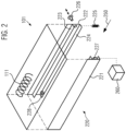
- Fig. 2 shows an embodiment of such a receptacle or frame 220, as shown in the Fig. 1 is only shown schematically.
- the running direction 250 of the film is shown here as an arrow for the sake of clarity.
- the frame 220 includes two guides 221 and 222.
- each guide 221 and 222 respectively, includes a lower rail 224 and an upper rail 223, between which a sealing plate can be inserted. It can also be provided that only one rail, for example the lower rail pointing away from the heating element 111 of the upper tool, is provided for each guide, on which the sealing plate can rest in the inserted state.
- the frame 220 includes a receiving surface limited on all four sides of the frame, into which a sealing plate can be inserted.
- a sealing plate can be moved or removed along or against the direction of travel 250.
- the guides 221 and 222 can include a stop 227, up to which a sealing plate can be pushed into the frame 220.
- the stop 227 is only provided as part of the guide 221 or in it, in particular between. It goes without saying that this stop 227 can also be provided in both guides 221 and 222 in order to avoid tilting or tilting of a sealing plate.
- the stop 227 does not have to be arranged along the guides 221 and/or 222 in the direction shown here.
- the stop 227 is arranged here in the direction of the origin of the film web, so that the sealing plate runs counter to the running direction 250 of the film Frame 220 is introduced and can be removed from frame 220 parallel to the running direction.
- the stop 227 is arranged at the opposite end of the guide or guides. In this embodiment, a sealing plate is then inserted into the frame in the running direction 250 of the film and removed from the frame 220 in the opposite direction to the running direction 250 of the film.
- the frame 220 can include a releasable fastening means 226 with which the sealing plate can be fastened in the frame.
- This fastening means 226 can preferably be designed as a fastening means which can be released without tools.
- the fastening means can be designed as a screw with a knob that can be easily loosened by an operator.
- a corresponding opening in the frame may allow insertion of the fastener 226 and removal of the fastener.
- the frame can include a pressure element 225, which is designed so that when a sealing plate is inserted, it presses the sealing plate in the direction of the heating element 111 of the upper tool 101. This results in a reliable heat transfer from the heating element 111 to an inserted sealing plate.
- a spring is only shown schematically.
- the pressure element 225 is firmly connected to the frame and/or a part of the upper tool 101 and a lower rail 224 of one or each guide 221 and 222 pulls or pushes in the direction of the heating element 111.
- the frame 220 for the sealing plate can be arranged movably relative to the upper tool 101.
- a drive element 260 such as an electric motor, can be provided.
- This drive element 260 can either move the frame 220 as a whole (i.e. with the sealing plate inserted) or only the sealing plate arranged in the frame (for example along the guides 221 and 222), so that the sealing plate can be moved into a position that is easier to remove from the frame can (for example in the running direction 250 of the film out of the upper tool 111).
- the recording can include an identification element 228.
- This identification element can be realized, for example, as a material bulge and with a corresponding identification element (see Fig. 4 ) of a sealing plate work together in such a way that inserting and/or removing the sealing plate from the frame 220 is only possible in a certain orientation of the sealing plate. This ensures that one sealing plate only can be removed from the frame 220 in the predetermined direction and/or inserted in the opposite direction to this direction.
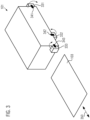
- Fig. 3 shows a further schematic embodiment of an upper tool 101 corresponding to a sealing station Fig. 1 .
- This embodiment is related to the Fig. 1 and 2 described embodiments can be combined.
- the upper tool 101 includes a number of further components 331 to 333.
- the components can be, for example, sensors and/or drive elements and/or control elements, such as computers.
- This embodiment is not limited in terms of the actual design of the components or their number.
- These are arranged here in such a way that they prevent the insertion and/or removal of a sealing plate 103 along or in the running direction 350 (for example by preventing the insertion into the frame from the Fig. 2 or into the guides.
- the components 331 to 333 are therefore in a movement range of the sealing plate when it is to be inserted or removed.
- Suitable fastening elements 341 to 343 are preferably provided for this purpose, which connect the respective components to the upper tool 101.
- the fastening elements 341 to 343 can, for example, be designed as rotating elements in order to enable the components 331 to 333 to be rotated along the arrow directions shown.
- the fastening elements 341 to 343 can also be designed as releasable connections (for example clamping devices or click connectors) in order to enable the components 331 to 333 to be released.
- the movement and/or removal or loosening of the components can be carried out without tools using the fastening elements, so that an operator can move or remove the components 331 to 333 at any time and without the need for tools in order to keep the range of movement of the sealing plate free and to remove it or to introduce.
- the invention is not limited with regard to the arrangement of the components 331 to 333 or with regard to their position relative to the upper tool 101 of the sealing station.
- the Fig. 4a and b show different embodiments of sealing plates 401 and 402 as part of a range of sealing plates.
- the range of sealing plates may consist of or include a variety of sealing plates (e.g. 2 or more).
- the representation of only 2 sealing plates corresponds Figures 4a and 4b is therefore not to be understood as limiting. Any other number of sealing plates can also be provided as an assortment.
- the sealing plate includes recesses 411 through which heat conduction to a package is not possible.
- the sealing plate can also include material bulges or similar elements which point in the direction of the packs to be sealed when the sealing plate is inserted during operation of the sealing plate in order to ensure sufficient heat transfer.
- These elements include rectangular structure. This is not mandatory and another structure can also be provided.
- the sealing plate 401 also optionally includes an identification element 412. This can correspond to the ones already mentioned in relation to Fig. 2
- the identification element 228 described can be designed so that insertion of the sealing plate 401 is only possible in a certain orientation in which the identification elements can interact with one another.
- FIG. 4b Another sealing plate 402 is shown, which may be provided as part of the range of sealing plates.
- the sealing plate 402 includes recesses 421 or material bulges or corresponding elements for transmitting heat, which are circular.
- this version is also not restrictive and it can be provided that the sealing plates of an assortment of sealing plates differ in terms of the recesses or material bulges or corresponding elements in order to achieve a region shaped in a certain way for heat transfer to the packaging in order to seal the packaging in terms of the shape of the Distinguish in pairs in the shaped area. Any two sealing plates of an assortment of sealing plates can each have a different shape of the shaped area.
- Sealing plate shown includes a corresponding identification element 422, which can interact with an identification element of the frame of the sealing station holder to enable insertion of the sealing plate in only a predetermined orientation.
Landscapes
- Engineering & Computer Science (AREA)
- Mechanical Engineering (AREA)
- Physics & Mathematics (AREA)
- Thermal Sciences (AREA)
- Package Closures (AREA)
- Closing Of Containers (AREA)
Abstract
Description
- Die vorliegende Erfindung betrifft eine Siegelstation zum Siegeln von Verpackungen gemäß Anspruch 1 sowie ein Sortiment von Siegelplatten gemäß Anspruch 12.
- Aus dem Stand der Technik sind Siegelstationen zum Siegeln von Verpackungen grundsätzlich bekannt. Die Siegelstationen umfassen üblicherweise ein Oberwerkzeug und ein Unterwerkzeug, die relativ zueinander bewegbar angeordnet sind. In dem Unterwerkzeug können Aufnahmen oder Mulden vorgesehen sein, um eine tiefgezogene Verpackung aufzunehmen. Weiterhin kann zwischen dem Oberwerkzeug und dem Unterwerkzeug eine Folie eingebracht werden, mit der ein Verschließen der eingebrachten Verpackungen realisiert werden kann.
- Dazu umfasst das Oberwerkzeug eine Siegelplatte, die in ihrer Form und Kontur so ausgestaltet ist, dass sie einen Wärmeübertrag an den zu siegelnden Teil der Verpackung bzw. Folie bewirken kann.
- Während bekannte Siegelstationen zuverlässig einen kontinuierlichen Betrieb gewährleisten können, kann aufgrund von Veränderungen in den Anforderungen an die Verpackungen (bspw. Deren Form) ein Umbau der Siegelstation erforderlich sein. Dabei kann die Siegelplatte entfernt und durch eine andere Siegelplatte ersetzt werden, um den sich verändernden Anforderungen an die zu siegelnden Verpackungen Rechnung zu tragen.
- Dieses Umrüsten der Siegelstation erfordert jedoch einen Stillstand der Siegelstation und umfangreiche mechanische Umrüstarbeiten, die zu langen Stillstandszeiten führen können.
- Ausgehend vom bekannten Stand der Technik besteht die zu lösende technische Aufgabe darin, eine Siegelstation sowie Siegelplatten anzugeben, die ein möglichst einfaches Umrüsten einer Siegelstation zur Verwendung einer anderen Siegelplatte erlauben und gleichzeitig ein Umrüsten in kurzer Zeit ermöglichen.
- Diese Aufgabe wird erfindungsgemäß durch die Siegelstation nach Anspruch 1 sowie das Sortiment von Siegelplatten umfassend wenigstens zwei Siegelplatten gemäß unabhängigem Anspruch 12 gelöst. Vorteilhafte Weiterbildungen der Erfindung sind in den Unteransprüchen erfasst.
- Die erfindungsgemäße Siegelstation zum Siegeln von Verpackungen umfasst ein Oberwerkzeug und ein Unterwerkzeug mit wenigstens einer Aufnahme für eine Verpackung, wobei zum Siegeln eine Folie zwischen dem Oberwerkzeug und dem Unterwerkzeug entlang einer Laufrichtung der Folie geführt werden kann und das Oberwerkzeug und das Unterwerkzeug relativ zueinander bewegbar sind, um ein Siegeln einer Verpackung mit der Folie zu bewirken, wobei das Oberwerkzeug eine Aufnahme zum Aufnehmen einer Siegelplatte aufweist, wobei die Aufnahme so ausgebildet ist, dass eine Siegelplatte in oder entgegen der Laufrichtung aus der Aufnahme entnommen werden kann.
- Die Laufrichtung der Folie entspricht dabei der Bewegungsrichtung der Folie und/oder der Bewegungsrichtung der Verpackungen zumindest zwischen dem Oberwerkzeug und dem Unterwerkzeug. Dass die Siegelplatte in oder entgegen der Laufrichtung aus der Aufnahme entnommen werden kann, ist hier so zu verstehen, dass zumindest eine Bewegungskomponente der Siegelplatte bei dem Entnehmen der Siegelplatte aus der Aufnahme parallel zur Laufrichtung der Folie ist und dementsprechend in Richtung stromab- oder stromaufwärts der Bewegungsrichtung der Folie verläuft.
- Mit dieser Siegelstation kann eine Siegelplatte ohne negative Beeinflussung der Folie und insbesondere eines kontinuierlichen Folienbandes, das sich stromauf der Siegelstation erstreckt und dieser zugeführt wird, erfolgen. Gleichzeitig ist eine Beeinflussung des Betriebs oder eine separate Verstellung der Position des Oberwerkzeugs und des Unterwerkzeugs nicht notwendig, sodass auch das Umrüsten der Siegelstation für den Bediener einfacher durchgeführt werden kann.
- In einer Ausführungsform ist vorgesehen, dass die Aufnahme wenigstens zwei parallel zur Laufrichtung angeordnete Führungen umfasst, wobei eine Siegelplatte entlang den Führungen in die Aufnahme eingeführt und aus der Aufnahme entnommen werden kann. Die Führungen erleichtern das Herausnehmen und Einsetzen der Siegelplatte und vermeiden Beschädigungen.
- Weiterhin kann vorgesehen sein, dass die Aufnahme lösbare Befestigungsmittel zum Befestigen der Siegelplatte in der Aufnahme umfasst. Als lösbares Befestigungsmittel kommen hier beispielsweise Schrauben oder Klickverbindungen infrage. Diese können besonders einfach gelöst und befestigt werden, so dass ein Austausch der Siegelplatte und ausreichende Befestigung in der Siegelstation ermöglicht wird.
- In einer Ausführungsform umfasst das Oberwerkzeug ein Heizelement zum Übertragen von Wärme durch eine Siegelplatte auf die Folie zum Siegeln der Verpackung. Ein Austausch der Siegelplatte erfordert somit nur den Austausch der für die Form des Siegelns relevanten Teile der Siegelstation, was die Ausführung der Siegelplatte mit möglichst geringem Gewicht ermöglicht, wobei dennoch ein zuverlässiges Erwärmen der Folie gewährleistet wird.
- In einer Weiterbildung dieser Ausführungsform ist vorgesehen, dass die Aufnahme ein Druckelement umfasst, das ausgebildet ist, eine in der Aufnahme angeordnete Siegelplatte gegen das Heizelement zu drücken. Hierdurch wird eine zuverlässige Wärmeübertragung an die Siegelplatte und damit auch an die Folie gewährleistet.
- In einer Ausführungsform umfasst die Aufnahme einen beweglich angeordneten Rahmen, in den eine Siegelplatte eingelegt werden kann, wobei der Rahmen in oder entgegen der Laufrichtung bewegbar angeordnet ist, um eine Siegelplatte zu entnehmen.
- Hiermit wird das Zuführen und Entfernen einer Siegelplatte weiter vereinfacht. Der Rahmen in dieser Ausführungsform kann auch als Rahmen entsprechend der vorangegangenen Ausführungsformen ausgeführt sein.
- Insbesondere kann vorgesehen sein, dass der Rahmen ein Identifikationselement umfasst, das ein Einführen einer Siegelplatte nur in einer vorgegebenen Ausrichtung ermöglicht. Diese Ausführungsform gewährleistet korrektes Positionieren der Siegelplatte.
- Ferner kann das Oberwerkzeug feststehend und das Unterwerkzeug bewegbar angeordnet sein, um ein Siegeln einer Verpackung mit der Folie zu ermöglichen. Hierdurch wird ein Bewegen des Oberwerkzeugs zum Wechseln der Siegelplatte vermieden, was die Handhabung für einen Bediener vereinfacht.
- In einer weiteren Ausführungsform wird ein Bewegen einer Siegelplatte zum Entnehmen der Siegelplatte aus der Aufnahme durch ein Antriebselement bewirkt. Bei dem Antriebselement kann es sich insbesondere um einen Elektromotor handeln. Diese Ausführungsform vereinfacht den Austausch der Siegelplatte und deren Handhabung insbesondere bei Siegelplatten mit hohem Gewicht.
- In einer weiteren Ausführungsform ist vorgesehen, dass eine Komponente der Siegelstation, die sich im normalen Betrieb der Siegelstation in einem Bewegungsbereich einer Siegelplatte befindet, beweglich und/oder von der Siegelstation entfernbar ausgebildet ist, sodass die Komponente vor einer Entnahme oder einer Einführung einer Siegelplatte entfernt werden kann. Mit dieser Ausführungsform wird der Wechsel der Siegelplatte vereinfacht.
- Hierbei kann auch vorgesehen sein, dass die Komponente ausgebildet ist, werkzeuglos bewegt und/oder von der Siegelstation entfernt zu werden. Ein werkzeugloses Bewegen oder Entfernen der Komponente von der Siegelstation ist hier so zu verstehen, dass für das Bewegen oder Entfernen der Komponente kein Werkzeug, wie etwa ein Schraubenzieher, notwendig ist. Dazu kann vorgesehen sein, dass die Komponente über durch einen Menschen ohne den Einsatz von Werkzeug lösbare Befestigungselemente, wie beispielsweise Druckelemente oder Klemmelemente, gelöst werden kann.
- In einer Ausführungsform ist die Siegelstation zur Verwendung mit einer Tiefziehverpackungsmaschine ausgebildet. Die Siegelstation eignet sich besonders vorteilhaft, um bei Tiefziehverpackungsmaschinen, die eine Verpackung durch Tiefziehen erzeugen und diese mit einer Oberfolie siegeln, zum Einsatz zu kommen, da hier zwei relativ zueinander bewegte Elemente (die Oberfolie und die Verpackungsmulden) zum Einsatz kommen und die erfindungsgemäße Anordnung der austauschbaren Siegelplatte hier ein einfaches Umrüsten gewährleistet.
- Erfindungsgemäß ist ferner ein Sortiment von Siegelplatten umfassend wenigstens zwei Siegelplatten vorgesehen, wobei die Siegelplatten ausgebildet sind, in einer Siegelstation nach einer der vorangegangenen Ausführungsformen verwendet zu werden. Die Siegelplatten können sich insbesondere hinsichtlich der durch das Siegeln gesiegelten Formen in der Folie unterscheiden, wodurch ein Anpassen an unterschiedliche herzustellende Verpackungen ermöglicht wird. Durch das Sortiment zusammen mit der Siegelstation ist ein einfacher Austausch der Siegelplatte möglich.
- In einer Ausführungsform ist vorgesehen, dass jede Siegelplatte ein komplementäres Identifikationselement umfasst, das mit einem Identifikationselement eines Rahmens der Aufnahme der Siegelstation interagieren kann, um ein Einführen der Siegelplatte in nur einer vorgegebenen Ausrichtung zu ermöglichen. Das komplementäre Identifikationselement der Siegelplatte und das Identifikationselement des Rahmens können dabei im Sinne eines "Schlüssel-Schloss-Prinzips" ausgestaltet sein, so dass die Siegelplatte nur in genau einer vorgegebenen Ausrichtung in die Siegelstation eingesetzt werden kann. Dies vermeidet Beschädigungen und gewährleistet den korrekten Betrieb der Siegelstation auch nach Austausch der Siegelplatte.
-
- Fig. 1
- zeigt eine Ausführungsform einer Siegelstation;
- Fig. 2
- zeigt eine Ausführungsform eines Rahmens mit Führung;
- Fig. 3
- zeigt eine Siegelstation mit weiteren Komponenten im Bewegungsbereich der Siegelplatte gemäß einer Ausführungsform;
- Fig. 4
- zeigt verschiedene Siegelplatten eines Sortiments von Siegelplatten gemäß einer Ausführungsform.
-
Fig. 1 zeigt eine Ausführungsform einer Siegelstation 100. Die Siegelstation 100 ist zum Siegeln von Verpackungen beispielsweise als Teil einer Tiefziehverpackungsmaschine ausgestaltet. Die Verpackungen können der Siegelstation zugeführt und durch Aufbringen einer weiteren Folie und Erwärmen dieser versiegelt werden. Dieses Konzept ist grundsätzlich bekannt. - Die Siegelstation umfasst hierzu ein Oberwerkzeug 101 sowie ein Unterwerkzeug 102, die relativ zueinander beweglich angeordnet sind. Das Unterwerkzeug 102 kann wenigstens eine Aufnahme 121 umfassen, in die beispielsweise eine vorgeformte und tiefgezogene Verpackung eingebracht werden kann. Diese Ausgestaltung ist besonders bevorzugt bei Verwendung der Siegelstation 100 in Kombination mit einer Tiefziehverpackungsmaschine. Die Erfindung ist jedoch nicht darauf beschränkt, sodass auch andere Ausgestaltungen des Unterwerkzeugs denkbar sind.
- Das Oberwerkzeug 101 kann ein Heizelement 111 umfassen, mit dessen Hilfe Wärme erzeugt werden kann, die auf eine auf die Verpackung in der Aufnahme 121 aufgebrachte Oberfolie einwirken kann, um ein Siegeln der Verpackung zu bewirken. Das Heizelement 111 ist hier nur allgemein dargestellt kann jedoch beispielsweise eine oder mehrere Heizstäbe umfassen, die mittels elektrischem Strom Wärme erzeugen. Auch andere Wärmequellen sind hier denkbar und die Erfindung diesbezüglich nicht beschränkt. Bevorzugt kann auch ein Heizelement vorgesehen sein, das Wärme über einen möglichst großen Teil des Bereichs des Oberwerkzeugs, der mit Verpackungsmaterial in Kontakt kommt, abgibt, sodass ein gleichmäßiges Erwärmen bewirkt werden kann.
- Dazu kann eine Oberfolie der Siegelstation 100 in der hier dargestellten Ausführungsform als Folienbahn 140 entsprechend der dargestellten Transportrichtung (Pfeil) zugeführt werden.
- Oberwerkzeug 101 und Unterwerkzeug 102 sind relativ zueinander bewegbar (beispielsweise mit Hilfe eines Elektromotors 150), so dass zwischen dem Oberwerkzeug und dem Unterwerkzeug die Folie 140 mit den in die Aufnahmen 121 eingebrachten Verpackungen in Anlage gebracht werden kann, um das Siegeln zu bewirken.
- Der Siegelstation 100 kann erfindungsgemäß eine Siegelplatte 103 zugeführt werden, die eine Kontur aufweist, die ein Siegeln der Verpackungen in der Siegelstation 100 ermöglicht. Die Kontur kann beispielsweise über entsprechende Ausnahmen 131 in der Siegelplatte 103 bereitgestellt werden, durch die kein Wärmeeintrag auf Verpackungen in der Siegelstation erfolgt. Alternativ oder zusätzlich können in der Siegelplatte 103 auch Erhebungen oder Vertiefungen angeordnet sein, um den Wärmeeintrag an den vorgesehenen Stellen auf die zu siegelnde Verpackung zu bewirken.
- Erfindungsgemäß ist vorgesehen, dass die Siegelplatte 103 dem Oberwerkzeug 101 entlang einer Richtung zugeführt werden kann, die entweder parallel oder entgegengesetzt zu der Laufrichtung (Pfeil) der Folie 140 verläuft.
- Hiermit wird erreicht, dass ein Wechsel der Siegelplatte 103 durch einen Bediener möglichst einfach durchgeführt werden kann, ohne dass Modifikationen oder Umrüstarbeiten an der Siegelstation 100 vorgenommen werden müssten.
- Dazu kann in einer bevorzugten Ausführungsform vorgesehen sein, dass nicht das Oberwerkzeug 101 in Richtung des Unterwerkzeugs 102 bewegt wird, um das Siegeln zu bewirken, sondern dass lediglich das Unterwerkzeug 102 beweglich angeordnet ist und das Oberwerkzeug 101 feststeht. Dies bewirkt eine sichere und zuverlässige Positionierung des Oberwerkzeugs und kann insbesondere Verletzungsrisiken beim Entnehmen der Siegelplatte 103 oder bei ihrem Einlegen reduzieren.
- Es kann vorgesehen sein, dass das Oberwerkzeug 101 eine Aufnahme 112, die insbesondere als Rahmen ausgestaltet sein kann oder einen solchen umfassen kann, umfasst, in den die Siegelplatte 103 eingelegt und/oder eingeführt werden kann. Der Rahmen kann dabei, wie in weiteren Ausführungsformen beschrieben, auch beweglich ausgeführt sein, um diesen zusammen mit der Siegelplatte 103 relativ zum Oberwerkzeug 101 zu bewegen und ein Entnehmen bzw. Zuführen der Siegelplatte zu vereinfachen.
-
Fig. 2 zeigt eine Ausführungsform einer solchen Aufnahme bzw. eines solchen Rahmens 220, wie er in derFig. 1 lediglich schematisch dargestellt ist. Die Laufrichtung 250 der Folie ist hier der Übersichtlichkeit halber als Pfeil gezeigt. - In der hier gezeigten Ausführungsform umfasst der Rahmen 220 zwei Führungen 221 und 222. In der hier gezeigten Ausführungsform umfasst jede Führung 221 bzw. 222 eine untere Schiene 224 und eine obere Schiene 223, zwischen denen eine Siegelplatte eingeführt werden kann. Es kann auch vorgesehen sein, dass lediglich eine Schiene, beispielsweise die untere, von dem Heizelement 111 des Oberwerkzeugs wegweisende Schiene, für jede Führung vorgesehen ist, auf der die Siegelplatte in eingeführtem Zustand aufliegen kann.
- Alternativ dazu kann auch vorgesehen sein, dass der Rahmen 220 eine an allen vier Seiten des Rahmens begrenzte Aufnahmefläche umfasst, in die eine Siegelplatte eingelegt werden kann. Auch andere Ausführungsformen sind hier denkbar, sofern sie ein Bewegen oder Entnehmen einer Siegelplatte entlang oder entgegen der Laufrichtung 250 ermöglichen.
- Die Führungen 221 und 222 können, um ein korrektes Positionieren einer Siegelplatte sicherzustellen, einen Anschlag 227 umfassen, bis zu dem ein Einschieben einer Siegelplatte in den Rahmen 220 möglich ist. In der hier dargestellten Ausführungsform ist der Anschlag 227 nur als Teil der Führung 221 vorgesehen bzw. in dieser, insbesondere zwischen. Es versteht sich, dass dieser Anschlag 227 auch in beiden Führungen 221 und 222 vorgesehen sein kann, um ein Verkanten oder Schrägstellen einer Siegelplatte zu vermeiden.
- Ferner muss der Anschlag 227 nicht in der hier dargestellten Richtung entlang der Führungen 221 und/oder 222 angeordnet sein. Der Anschlag 227 ist hier in Richtung des Ursprungs der Folienbahn angeordnet, so dass die Siegelplatte entgegen der Laufrichtung 250 der Folie in den Rahmen 220 eingeführt und parallel zur Laufrichtung aus dem Rahmen 220 entnommen werden kann. Es kann jedoch alternativ auch vorgesehen sein, dass der Anschlag 227 am gegenüberliegenden Ende der Führung oder der Führungen angeordnet ist. In dieser Ausführungsform wird eine Siegelplatte dann in Laufrichtung 250 der Folie in den Rahmen eingeführt und entgegen der Laufrichtung 250 der Folie aus dem Rahmen 220 entnommen.
- Weiterhin kann der Rahmen 220 unabhängig von der Ausgestaltung der Führung ein lösbares Befestigungsmittel 226 umfassen, mit dem die Siegelplatte in dem Rahmen befestigt werden kann. Bevorzugt kann dieses Befestigungsmittel 226 als werkzeuglos lösbares Befestigungsmittel ausgestaltet sein. Beispielsweise kann das Befestigungsmittel als Schraube mit Knauf ausgestaltet sein, die von einem Bediener einfach gelöst werden kann. Eine entsprechende Öffnung in dem Rahmen kann ein Einführen des Befestigungsmittels 226 und ein Entnehmen des Befestigungsmittels erlauben.
- Weiterhin kann der Rahmen ein Druckelement 225 umfassen, das so ausgestaltet ist, dass es bei Einlegen einer Siegelplatte die Siegelplatte in Richtung des Heizelements 111 des Oberwerkzeugs 101 drückt. Hierdurch wird ein zuverlässiger Wärmeübertrag von dem Heizelement 111 an einer eingelegten Siegelplatte bewirkt. In
Figur 2 ist hierzu lediglich schematisch eine Feder gezeigt. Es kann insbesondere vorgesehen sein, dass das Druckelement 225 fest mit dem Rahmen und/oder einem Teil des Oberwerkzeugs 101 verbunden ist und eine untere Schiene 224 einer oder jeder Führung 221 und 222 in Richtung des Heizelements 111 zieht oder drückt. - Der Rahmen 220 für die Siegelplatte kann beweglich relativ zum Oberwerkzeug 101 angeordnet sein. Dazu kann ein Antriebselement 260, wie beispielsweise ein Elektromotor vorgesehen sein. Dieses Antriebselement 260 kann entweder den Rahmen 220 insgesamt (also mit eingelegter Siegelplatte) oder lediglich die in dem Rahmen angeordnete Siegelplatte (beispielsweise entlang der Führungen 221 und 222) bewegen, so dass die Siegelplatte in einen für die Entnahme aus dem Rahmen einfachere Position bewegt werden kann (beispielsweise in Laufrichtung 250 der Folie aus dem Oberwerkzeug 111 heraus).
- Weiterhin kann die Aufnahme ein Identifikationselement 228 umfassen. Dieses Identifikationselement kann beispielsweise als Materialauswölbung realisiert sein und mit einem korrespondierenden Identifikationselement (siehe hierzu
Fig. 4 ) einer Siegelplatte so zusammenwirken, dass ein Einführen und/oder Entnehmen der Siegelplatte aus dem Rahmen 220 nur in einer bestimmten Ausrichtung der Siegelplatte möglich ist. Hierdurch wird gewährleistet, dass eine Siegelplatte nur in der vorgegebenen Richtung aus dem Rahmen 220 entnommen und/oder entgegen dieser Richtung eingeführt werden kann. -
Fig. 3 zeigt eine weitere schematische Ausführungsform eines Oberwerkzeugs 101 einer Siegelstation entsprechendFig. 1 . Diese Ausführungsform ist mit der im Zusammenhang mit denFig. 1 und2 beschriebenen Ausführungsformen kombinierbar. - In der hier gezeigten Ausführungsform umfasst das Oberwerkzeug 101 eine Reihe weiterer Komponenten 331 bis 333. Bei den Komponenten kann es sich beispielsweise um Sensoren und/oder Antriebselemente und/oder Steuerelemente, wie Computer, handeln. Diese Ausführungsform ist hinsichtlich der tatsächlichen Ausgestaltung der Komponenten sowie deren Anzahl nicht beschränkt. Diese sind hier so angeordnet, dass sie ein Einführen und/oder Entnehmen einer Siegelplatte 103 entlang oder in Laufrichtung 350 verhindern (indem sie beispielsweise die Einführung in den Rahmen aus der
Fig. 2 bzw. in die Führungen verhindern. Die Komponenten 331 bis 333 befinden sich somit in einem Bewegungsbereich der Siegelplatte, wenn diese eingeführt oder entnommen werden soll. - Da die Komponenten 331 - 333 jedoch für den Betrieb der Siegelstation notwendig sein können, ist in dieser Ausführungsform vorgesehen, dass die Komponenten, die sich in dem Bewegungsbereich der Siegelplatte befinden, beweglich gelagert sind und/oder von dem Oberwerkzeug 101 entfernt werden können. Bevorzugt sind dazu geeignete Befestigungselemente 341 bis 343 vorgesehen, die die jeweiligen Komponenten mit dem Oberwerkzeug 101 verbinden. Die Befestigungselemente 341 bis 343 können beispielsweise als Drehelemente ausgestaltet sein, um ein Drehen der Komponenten 331 bis 333 entlang der gezeigten Pfeilrichtungen zu ermöglichen. Alternativ können die Befestigungselemente 341 bis 343 auch als lösbare Verbindungen (beispielsweise Klemmeinrichtungen oder Klickverbinder) ausgestaltet sein, um ein Lösen der Komponenten 331 bis 333 zu ermöglichen. Besonders bevorzugt ist das Bewegen und/oder Entfernen bzw. Lösen der Komponenten mittels der Befestigungselemente werkzeuglos durchführbar, sodass ein Bediener die Komponenten 331 bis 333 jederzeit und ohne Bedarf an Werkzeug Bewegen oder entfernen kann, um den Bewegungsbereich der Siegelplatte freizuhalten und diese zu entnehmen oder einzuführen.
- Die Erfindung ist hinsichtlich der Anordnung der Komponenten 331 bis 333 sowie hinsichtlich deren Position relativ zum Oberwerkzeug 101 der Siegelstation nicht beschränkt.
- Die
Fig. 4a und b zeigen unterschiedliche Ausführungsformen von Siegelplatten 401 und 402 als Teil eines Sortiments von Siegelplatten. Das Sortiment von Siegelplatten kann aus einer Vielzahl von Siegelplatten (beispielsweise 2 oder mehr) bestehen oder diese umfassen. Die Darstellung von lediglich 2 Siegelplatten entsprechendFiguren 4a und 4b ist daher nicht beschränkend zu verstehen. Auch eine beliebige andere Anzahl Siegelplatten kann als Sortiment vorgesehen sein. - In der
Fig. 4a umfasst die Siegelplatte Ausnehmungen 411, durch die eine Wärmeleitung auf eine Verpackung nicht möglich ist. Alternativ zu entsprechenden Ausnehmungen kann die Siegelplatte auch Materialauswölbungen oder ähnliche Elemente umfassen, die bei Einsetzen der Siegelplatte im Betrieb der Siegelplatte in Richtung der zu siegelnden Packungen weisen, um einen ausreichenden Wärmeübertrag sicherzustellen. In der hier gezeigten Ausführungsform derFig. 4a umfassen diese Elemente rechteckige Struktur. Dies ist so nicht zwingend und auch eine andere Struktur kann vorgesehen sein. - Die Siegelplatte 401 umfasst in der hier dargestellten Ausführungsform auch optional ein Identifikationselement 412. Dieses kann korrespondierend zu den bereits in Bezug auf die
Fig. 2 beschriebenen Identifikationselement 228 ausgeführt sein, so dass ein Einführen der Siegelplatte 401 nur in einer bestimmten Ausrichtung möglich ist, in der die Identifikationselemente miteinander wechselwirken können. - In der
Fig. 4b ist eine weitere Siegelplatte 402 gezeigt, die als Teil des Sortiments von Siegelplatten vorgesehen sein kann. - In dieser Ausführungsform umfasst die Siegelplatte 402 Ausnehmungen 421 oder Materialauswölbungen oder entsprechende Elemente zum Übertragen von Wärme, die kreisförmig ausgebildet sind. Grundsätzlich ist auch diese Ausführung nicht beschränkend und es kann vorgesehen sein, dass sich die Siegelplatten eines Sortiments von Siegelplatten hinsichtlich der Ausnehmungen oder Materialauswölbungen oder entsprechender Elemente zum Erzielen eines auf bestimmte Art geformten Bereichs zum Wärmeübertrag an die Verpackung zum Siegeln der Verpackung hinsichtlich der Form des geformten Bereichs paarweise unterscheiden. Zwei beliebige Siegelplatten eines Sortiments von Siegelplatten können als jeweils unterschiedliche Form des geformten Bereichs aufweisen.
- Auch die in
Fig. 4b gezeigte Siegelplatte umfasst ein korrespondierendes Identifikationselement 422, das mit einem Identifikationselement des Rahmens der Aufnahme der Siegelstation interagieren kann, um ein Einführen der Siegelplatte in nur einer vorgegebenen Ausrichtung zu ermöglichen.
Claims (13)
- Siegelstation (100) zum Siegeln von Verpackungen, die Siegelstation umfassend ein Oberwerkzeug (101) und ein Unterwerkzeug (102) mit wenigstens einer Aufnahme (121) für eine Verpackung, wobei zum Siegeln eine Folie (140) zwischen dem Oberwerkzeug (101) und dem Unterwerkzeug (102) entlang einer Laufrichtung der Folie (140) geführt werden kann und das Oberwerkzeug (101) und das Unterwerkzeug (102) relativ zueinander bewegbar sind, um ein Siegeln einer Verpackung mit der Folie zu bewirken, wobei das Oberwerkzeug (101) eine Aufnahme (112) zum Aufnehmen einer Siegelplatte (103) aufweist, wobei die Aufnahme (112) so ausgebildet ist, dass eine Siegelplatte in Laufrichtung aus der Aufnahme entnommen werden kann.
- Siegelstation (100) nach Anspruch 1, wobei die Aufnahme (112) wenigstens zwei parallel zur Laufrichtung angeordnete Führungen (221, 222) umfasst, wobei eine Siegelplatte (103) entlang den Führungen (221, 222) in die Aufnahme (112) eingeführt und aus der Aufnahme entnommen werden kann.
- Siegelstation (100) nach Anspruch 1 oder 2, wobei die Aufnahme (112) lösbare Befestigungsmittel (226) zum Befestigen der Siegelplatte (103) in der Aufnahme umfasst.
- Siegelstation (100) nach einem der Ansprüche 1 bis 3, wobei das Oberwerkzeug (101) ein Heizelement (111) zum Übertragen von Wärme durch eine Siegelplatte (103) auf die Folie (140) zum Siegeln der Verpackung umfasst.
- Siegelstation (100) nach Anspruch 4, wobei die Aufnahme (112) ein Druckelement (225) umfasst, das ausgebildet ist, eine in der Aufnahme (112) angeordnete Siegelplatte (103) gegen das Heizelement (111) zu drücken.
- Siegelstation (100) nach einem der Ansprüche 1 bis 5, wobei die Aufnahme (112) einen beweglich angeordneten Rahmen (220) umfasst, in den eine Siegelplatte (103) eingelegt werden kann, wobei der Rahmen in Laufrichtung bewegbar angeordnet ist, um eine Siegelplatte zu entnehmen.
- Siegelstation (100) nach Anspruch 6, wobei der Rahmen (220) ein Identifikationselement (228) umfasst, das ein Einführen einer Siegelplatte (103) nur in einer vorgegebenen Ausrichtung ermöglicht.
- Siegelstation (100) nach einem der Ansprüche 1 bis 7, wobei das Oberwerkzeug (101) feststehend und das Unterwerkzeug (102) bewegbar angeordnet ist, um ein Siegeln einer Verpackung mit der Folie (140) zu ermöglichen.
- Siegelstation (100) nach einem der Ansprüche 1 bis 8, wobei ein Bewegen einer Siegelplatte (103) zum Entnehmen der Siegelplatte aus der Aufnahme (112) durch ein Antriebselement (260) bewirkt wird.
- Siegelstation (100) nach einem der Ansprüche 1 bis 9, wobei eine Komponente (331 - 333) der Siegelstation (100), die sich im normalen Betrieb der Siegelstation (100) in einem Bewegungsbereich einer Siegelplatte (103) befindet, beweglich und/oder von der Siegelstation entfernbar ausgebildet ist, sodass die Komponente (331 - 333) vor einer Entnahme oder einer Einführung einer Siegelplatte (103) entfernt werden kann.
- Siegelstation (100) nach Anspruch 10, wobei die Komponente (331 - 333) ausgebildet ist, werkzeuglos bewegt und/oder von der Siegelstation entfernt zu werden.
- Sortiment von Siegelplatten umfassend wenigstens zwei Siegelplatten (401, 402), wobei die Siegelplatten (401, 402) ausgebildet sind, in einer Siegelstation (100) nach einem der Ansprüche 1 bis 11 verwendet zu werden.
- Sortiment nach Anspruch 12, wobei jede Siegelplatte (401, 402) ein komplementäres Identifikationselement (412, 422) umfasst, das mit einem Identifikationselement (228) eines Rahmens der Aufnahme (112) der Siegelstation (100) interagieren kann, um ein Einführen der Siegelplatte in nur einer vorgegebenen Ausrichtung zu ermöglichen.
Applications Claiming Priority (1)
| Application Number | Priority Date | Filing Date | Title |
|---|---|---|---|
| DE102022120764.1A DE102022120764A1 (de) | 2022-08-17 | 2022-08-17 | Siegelstation zum Siegeln von Verpackungen |
Publications (2)
| Publication Number | Publication Date |
|---|---|
| EP4335627A1 true EP4335627A1 (de) | 2024-03-13 |
| EP4335627B1 EP4335627B1 (de) | 2025-12-24 |
Family
ID=87557706
Family Applications (1)
| Application Number | Title | Priority Date | Filing Date |
|---|---|---|---|
| EP23189701.8A Active EP4335627B1 (de) | 2022-08-17 | 2023-08-04 | Siegelstation zum siegeln von verpackungen |
Country Status (3)
| Country | Link |
|---|---|
| EP (1) | EP4335627B1 (de) |
| DE (1) | DE102022120764A1 (de) |
| ES (1) | ES3063059T3 (de) |
Citations (4)
| Publication number | Priority date | Publication date | Assignee | Title |
|---|---|---|---|---|
| EP1228853A2 (de) * | 2001-02-06 | 2002-08-07 | I.L.P.R.A. S.P.A. | Vorrichtung zum Verschweissen von Folienmaterial |
| ITMI20090163A1 (it) * | 2009-02-09 | 2010-08-10 | Termomec Srl | Macchina per il confezionamento di vaschette, particolarmente per il settore alimentare. |
| WO2018220574A1 (en) * | 2017-06-01 | 2018-12-06 | Machsolutions Sa | Apparatus for manufacturing containers |
| WO2019229622A1 (en) * | 2018-05-29 | 2019-12-05 | Ca.Ve.Co. S.R.L. | Thermo-sealing machine |
Family Cites Families (7)
| Publication number | Priority date | Publication date | Assignee | Title |
|---|---|---|---|---|
| DE10108163A1 (de) * | 2001-02-20 | 2002-08-29 | Ps Systempack Gmbh | Vorrichtung an einer Tiefzieh-Verpackungsmaschine |
| DE202004016538U1 (de) * | 2004-10-25 | 2005-02-10 | Variovac Ps Systempack Gmbh | Siegelstation an einer Verpackungsmaschine aufweisend eine oder mehrere einzeln handhabbare Siegelkassetten |
| DE102010009536A1 (de) * | 2010-02-26 | 2011-09-01 | Cfs Germany Gmbh | Verfahren zum Wechsel des Ober- und Unterwerkzeugs einer Verpackungsmaschine |
| DE102010056318B4 (de) * | 2010-12-27 | 2013-10-31 | Multivac Sepp Haggenmüller Gmbh & Co. Kg | Verpackungsmaschine mit einem anhebbaren und absenkbaren Werkzeug |
| DE102011113968A1 (de) * | 2011-09-21 | 2013-03-21 | Multivac Sepp Haggenmüller Gmbh & Co. Kg | Schalenverschließmaschine |
| DE102012003830A1 (de) * | 2012-02-29 | 2013-08-29 | Gea Cfs Germany Gmbh | Verpackungsmaschine mit einem auswechselbaren Werkzeug |
| ES2646768T3 (es) * | 2013-02-22 | 2017-12-15 | Multivac Sepp Haggenmüller Se & Co. Kg | Máquina de envasado por embutición profunda con estación de sellado y procedimiento |
-
2022
- 2022-08-17 DE DE102022120764.1A patent/DE102022120764A1/de active Pending
-
2023
- 2023-08-04 ES ES23189701T patent/ES3063059T3/es active Active
- 2023-08-04 EP EP23189701.8A patent/EP4335627B1/de active Active
Patent Citations (4)
| Publication number | Priority date | Publication date | Assignee | Title |
|---|---|---|---|---|
| EP1228853A2 (de) * | 2001-02-06 | 2002-08-07 | I.L.P.R.A. S.P.A. | Vorrichtung zum Verschweissen von Folienmaterial |
| ITMI20090163A1 (it) * | 2009-02-09 | 2010-08-10 | Termomec Srl | Macchina per il confezionamento di vaschette, particolarmente per il settore alimentare. |
| WO2018220574A1 (en) * | 2017-06-01 | 2018-12-06 | Machsolutions Sa | Apparatus for manufacturing containers |
| WO2019229622A1 (en) * | 2018-05-29 | 2019-12-05 | Ca.Ve.Co. S.R.L. | Thermo-sealing machine |
Also Published As
| Publication number | Publication date |
|---|---|
| EP4335627B1 (de) | 2025-12-24 |
| DE102022120764A1 (de) | 2024-02-22 |
| ES3063059T3 (en) | 2026-04-15 |
Similar Documents
| Publication | Publication Date | Title |
|---|---|---|
| DE19810224C1 (de) | Montagemaschine | |
| AT517712B1 (de) | Greifersystem für eine Biegepresse | |
| EP3422494B1 (de) | Abtrennvorrichtung sowie verfahren zum abtrennen einer kabeltülle von einem kabel | |
| EP2292409A1 (de) | Werkzeugträger, Werkzeug und Arbeitsstation mit Werkzeugträger und daran befestigtem Werkzeug | |
| EP2511202A2 (de) | Fertigungs- und/oder Montagevorrichtung, insbesondere Blisterbefüllvorrichtung | |
| EP0965413A2 (de) | Anlage für die Durchführung einer Folge aus mehreren Montage- und/oder Bearbeitungsvorgängen an Werkstücken, insbesondere Kleinteilen | |
| EP3664959A1 (de) | Verfahren und vorrichtung zur bereitstellung von schrauben | |
| EP4335627B1 (de) | Siegelstation zum siegeln von verpackungen | |
| EP0918592A1 (de) | Fertigungs- und/oder montagevorrichtung | |
| EP2184118A1 (de) | Abgesetzter Niederhalter und Verfahren zum Entfernen von Blechteilen aus Stanzmaschinen | |
| DE1590787B2 (de) | Vorrihtung zum mechanischen verbinden eines elektrischen leiters mit einem klemmenteil | |
| EP3505355A1 (de) | Abschneidevorrichtung fuer endlosetiketten | |
| EP2741963A1 (de) | Einrichtung zum halten und positionieren von als tabletten, hartgelatinekapseln oder ähnlichem ausgebildeten pharmazeutischen produkten in einer verpackungsanlage | |
| DE102023107744B3 (de) | Vorrichtung zum Zuschneiden von Verpackungen | |
| EP4129575B1 (de) | Ring-montagevorrichtung sowie verfahren zum einstellen einer ring-montagevorrichtung | |
| DE10319411A1 (de) | Vorrichtung und Verfahren zum Stanznieten | |
| DE4332803C2 (de) | Vorrichtung zum automatischen Zuführen von Druckplatten zum Plattenzylinder einer Druckmaschine | |
| EP2845663B1 (de) | Biegepresse mit einem Biegewerkzeug aus mehreren Werkzeugelementen | |
| EP2796394A1 (de) | Verstellbarer Klammerstern | |
| DE202013004064U1 (de) | Siegelvorrichtung | |
| DE10001322B4 (de) | Verfahren zum automatischen Zuführen von Druckplatten an Druckmaschinen | |
| DE10354651B3 (de) | Schnellwechselsystem für eine werkstückspezifische Handhabungsvorrichtung zum Ergreifen und Transportieren von unterschiedlich geformten Werkstücken | |
| EP3710360A1 (de) | Beutelfüllvorrichtung und verfahren zum verarbeiten und befüllen von beuteln | |
| DE102019208622A1 (de) | Verpackungsmaschine mit folienklemmung | |
| DE102005040063B4 (de) | Vorrichtung zum Handhaben und Bearbeiten von plattenförmigen Werkstücken |
Legal Events
| Date | Code | Title | Description |
|---|---|---|---|
| PUAI | Public reference made under article 153(3) epc to a published international application that has entered the european phase |
Free format text: ORIGINAL CODE: 0009012 |
|
| STAA | Information on the status of an ep patent application or granted ep patent |
Free format text: STATUS: THE APPLICATION HAS BEEN PUBLISHED |
|
| AK | Designated contracting states |
Kind code of ref document: A1 Designated state(s): AL AT BE BG CH CY CZ DE DK EE ES FI FR GB GR HR HU IE IS IT LI LT LU LV MC ME MK MT NL NO PL PT RO RS SE SI SK SM TR |
|
| STAA | Information on the status of an ep patent application or granted ep patent |
Free format text: STATUS: REQUEST FOR EXAMINATION WAS MADE |
|
| 17P | Request for examination filed |
Effective date: 20240506 |
|
| RBV | Designated contracting states (corrected) |
Designated state(s): AL AT BE BG CH CY CZ DE DK EE ES FI FR GB GR HR HU IE IS IT LI LT LU LV MC ME MK MT NL NO PL PT RO RS SE SI SK SM TR |
|
| P01 | Opt-out of the competence of the unified patent court (upc) registered |
Free format text: CASE NUMBER: APP_5351/2025 Effective date: 20250131 |
|
| GRAP | Despatch of communication of intention to grant a patent |
Free format text: ORIGINAL CODE: EPIDOSNIGR1 |
|
| RIC1 | Information provided on ipc code assigned before grant |
Ipc: B29C 65/18 20060101AFI20250626BHEP Ipc: B29C 65/30 20060101ALI20250626BHEP Ipc: B65B 7/16 20060101ALI20250626BHEP Ipc: B65B 51/14 20060101ALI20250626BHEP Ipc: B65B 59/04 20060101ALI20250626BHEP |
|
| STAA | Information on the status of an ep patent application or granted ep patent |
Free format text: STATUS: GRANT OF PATENT IS INTENDED |
|
| INTG | Intention to grant announced |
Effective date: 20250731 |
|
| GRAS | Grant fee paid |
Free format text: ORIGINAL CODE: EPIDOSNIGR3 |
|
| GRAA | (expected) grant |
Free format text: ORIGINAL CODE: 0009210 |
|
| STAA | Information on the status of an ep patent application or granted ep patent |
Free format text: STATUS: THE PATENT HAS BEEN GRANTED |
|
| AK | Designated contracting states |
Kind code of ref document: B1 Designated state(s): AL AT BE BG CH CY CZ DE DK EE ES FI FR GB GR HR HU IE IS IT LI LT LU LV MC ME MK MT NL NO PL PT RO RS SE SI SK SM TR |
|
| REG | Reference to a national code |
Ref country code: CH Ref legal event code: F10 Free format text: ST27 STATUS EVENT CODE: U-0-0-F10-F00 (AS PROVIDED BY THE NATIONAL OFFICE) Effective date: 20251224 Ref country code: GB Ref legal event code: FG4D Free format text: NOT ENGLISH |
|
| REG | Reference to a national code |
Ref country code: DE Ref legal event code: R096 Ref document number: 502023002567 Country of ref document: DE |
|
| REG | Reference to a national code |
Ref country code: LT Ref legal event code: MG9D |
|
| PG25 | Lapsed in a contracting state [announced via postgrant information from national office to epo] |
Ref country code: NO Free format text: LAPSE BECAUSE OF FAILURE TO SUBMIT A TRANSLATION OF THE DESCRIPTION OR TO PAY THE FEE WITHIN THE PRESCRIBED TIME-LIMIT Effective date: 20260324 |
|
| PG25 | Lapsed in a contracting state [announced via postgrant information from national office to epo] |
Ref country code: FI Free format text: LAPSE BECAUSE OF FAILURE TO SUBMIT A TRANSLATION OF THE DESCRIPTION OR TO PAY THE FEE WITHIN THE PRESCRIBED TIME-LIMIT Effective date: 20251224 Ref country code: HR Free format text: LAPSE BECAUSE OF FAILURE TO SUBMIT A TRANSLATION OF THE DESCRIPTION OR TO PAY THE FEE WITHIN THE PRESCRIBED TIME-LIMIT Effective date: 20251224 |
|
| REG | Reference to a national code |
Ref country code: ES Ref legal event code: FG2A Ref document number: 3063059 Country of ref document: ES Kind code of ref document: T3 Effective date: 20260415 |
|
| PG25 | Lapsed in a contracting state [announced via postgrant information from national office to epo] |
Ref country code: RS Free format text: LAPSE BECAUSE OF FAILURE TO SUBMIT A TRANSLATION OF THE DESCRIPTION OR TO PAY THE FEE WITHIN THE PRESCRIBED TIME-LIMIT Effective date: 20260324 |
|
| PG25 | Lapsed in a contracting state [announced via postgrant information from national office to epo] |
Ref country code: LV Free format text: LAPSE BECAUSE OF FAILURE TO SUBMIT A TRANSLATION OF THE DESCRIPTION OR TO PAY THE FEE WITHIN THE PRESCRIBED TIME-LIMIT Effective date: 20251224 |
|
| REG | Reference to a national code |
Ref country code: NL Ref legal event code: MP Effective date: 20251224 |
|
| PG25 | Lapsed in a contracting state [announced via postgrant information from national office to epo] |
Ref country code: BG Free format text: LAPSE BECAUSE OF FAILURE TO SUBMIT A TRANSLATION OF THE DESCRIPTION OR TO PAY THE FEE WITHIN THE PRESCRIBED TIME-LIMIT Effective date: 20251224 |
|
| PG25 | Lapsed in a contracting state [announced via postgrant information from national office to epo] |
Ref country code: NL Free format text: LAPSE BECAUSE OF FAILURE TO SUBMIT A TRANSLATION OF THE DESCRIPTION OR TO PAY THE FEE WITHIN THE PRESCRIBED TIME-LIMIT Effective date: 20251224 |
|
| PG25 | Lapsed in a contracting state [announced via postgrant information from national office to epo] |
Ref country code: LT Free format text: LAPSE BECAUSE OF FAILURE TO SUBMIT A TRANSLATION OF THE DESCRIPTION OR TO PAY THE FEE WITHIN THE PRESCRIBED TIME-LIMIT Effective date: 20251224 |
|
| PG25 | Lapsed in a contracting state [announced via postgrant information from national office to epo] |
Ref country code: SM Free format text: LAPSE BECAUSE OF FAILURE TO SUBMIT A TRANSLATION OF THE DESCRIPTION OR TO PAY THE FEE WITHIN THE PRESCRIBED TIME-LIMIT Effective date: 20251224 |
|
| PG25 | Lapsed in a contracting state [announced via postgrant information from national office to epo] |
Ref country code: PL Free format text: LAPSE BECAUSE OF FAILURE TO SUBMIT A TRANSLATION OF THE DESCRIPTION OR TO PAY THE FEE WITHIN THE PRESCRIBED TIME-LIMIT Effective date: 20251224 |
|
| PG25 | Lapsed in a contracting state [announced via postgrant information from national office to epo] |
Ref country code: EE Free format text: LAPSE BECAUSE OF FAILURE TO SUBMIT A TRANSLATION OF THE DESCRIPTION OR TO PAY THE FEE WITHIN THE PRESCRIBED TIME-LIMIT Effective date: 20251224 |
|
| PG25 | Lapsed in a contracting state [announced via postgrant information from national office to epo] |
Ref country code: IS Free format text: LAPSE BECAUSE OF FAILURE TO SUBMIT A TRANSLATION OF THE DESCRIPTION OR TO PAY THE FEE WITHIN THE PRESCRIBED TIME-LIMIT Effective date: 20260424 Ref country code: PT Free format text: LAPSE BECAUSE OF FAILURE TO SUBMIT A TRANSLATION OF THE DESCRIPTION OR TO PAY THE FEE WITHIN THE PRESCRIBED TIME-LIMIT Effective date: 20260424 |
|
| PG25 | Lapsed in a contracting state [announced via postgrant information from national office to epo] |
Ref country code: CZ Free format text: LAPSE BECAUSE OF FAILURE TO SUBMIT A TRANSLATION OF THE DESCRIPTION OR TO PAY THE FEE WITHIN THE PRESCRIBED TIME-LIMIT Effective date: 20251224 |
|
| PG25 | Lapsed in a contracting state [announced via postgrant information from national office to epo] |
Ref country code: SK Free format text: LAPSE BECAUSE OF FAILURE TO SUBMIT A TRANSLATION OF THE DESCRIPTION OR TO PAY THE FEE WITHIN THE PRESCRIBED TIME-LIMIT Effective date: 20251224 |
|
| PG25 | Lapsed in a contracting state [announced via postgrant information from national office to epo] |
Ref country code: SE Free format text: LAPSE BECAUSE OF FAILURE TO SUBMIT A TRANSLATION OF THE DESCRIPTION OR TO PAY THE FEE WITHIN THE PRESCRIBED TIME-LIMIT Effective date: 20251224 |