EP4335415A2 - Replacement mitral valves - Google Patents
Replacement mitral valves Download PDFInfo
- Publication number
- EP4335415A2 EP4335415A2 EP24154744.7A EP24154744A EP4335415A2 EP 4335415 A2 EP4335415 A2 EP 4335415A2 EP 24154744 A EP24154744 A EP 24154744A EP 4335415 A2 EP4335415 A2 EP 4335415A2
- Authority
- EP
- European Patent Office
- Prior art keywords
- anchor
- atrial
- ventricular
- strut frame
- mitral valve
- Prior art date
- Legal status (The legal status is an assumption and is not a legal conclusion. Google has not performed a legal analysis and makes no representation as to the accuracy of the status listed.)
- Pending
Links
- 210000004115 mitral valve Anatomy 0.000 title claims abstract description 141
- 230000001746 atrial effect Effects 0.000 claims abstract description 239
- 230000002861 ventricular Effects 0.000 claims abstract description 198
- 210000005003 heart tissue Anatomy 0.000 claims abstract description 26
- 239000000725 suspension Substances 0.000 description 30
- 210000003709 heart valve Anatomy 0.000 description 26
- 238000000034 method Methods 0.000 description 22
- 230000008878 coupling Effects 0.000 description 16
- 238000010168 coupling process Methods 0.000 description 16
- 238000005859 coupling reaction Methods 0.000 description 16
- 239000000463 material Substances 0.000 description 14
- 230000007246 mechanism Effects 0.000 description 13
- 210000001519 tissue Anatomy 0.000 description 11
- 230000004044 response Effects 0.000 description 8
- 238000004519 manufacturing process Methods 0.000 description 7
- 239000002131 composite material Substances 0.000 description 6
- 238000009958 sewing Methods 0.000 description 6
- 229910003460 diamond Inorganic materials 0.000 description 5
- 239000010432 diamond Substances 0.000 description 5
- 210000002216 heart Anatomy 0.000 description 5
- 210000003484 anatomy Anatomy 0.000 description 4
- 238000013459 approach Methods 0.000 description 4
- 230000017531 blood circulation Effects 0.000 description 4
- 239000007943 implant Substances 0.000 description 4
- 210000005246 left atrium Anatomy 0.000 description 4
- 229910001000 nickel titanium Inorganic materials 0.000 description 4
- 238000004873 anchoring Methods 0.000 description 3
- 210000001765 aortic valve Anatomy 0.000 description 3
- 230000008901 benefit Effects 0.000 description 3
- 239000008280 blood Substances 0.000 description 3
- 210000004369 blood Anatomy 0.000 description 3
- 230000000747 cardiac effect Effects 0.000 description 3
- 239000011521 glass Substances 0.000 description 3
- 210000002837 heart atrium Anatomy 0.000 description 3
- 210000005240 left ventricle Anatomy 0.000 description 3
- HLXZNVUGXRDIFK-UHFFFAOYSA-N nickel titanium Chemical compound [Ti].[Ti].[Ti].[Ti].[Ti].[Ti].[Ti].[Ti].[Ti].[Ti].[Ti].[Ni].[Ni].[Ni].[Ni].[Ni].[Ni].[Ni].[Ni].[Ni].[Ni].[Ni].[Ni].[Ni].[Ni] HLXZNVUGXRDIFK-UHFFFAOYSA-N 0.000 description 3
- 238000001356 surgical procedure Methods 0.000 description 3
- RTAQQCXQSZGOHL-UHFFFAOYSA-N Titanium Chemical compound [Ti] RTAQQCXQSZGOHL-UHFFFAOYSA-N 0.000 description 2
- 210000000709 aorta Anatomy 0.000 description 2
- 210000005242 cardiac chamber Anatomy 0.000 description 2
- 238000000576 coating method Methods 0.000 description 2
- 230000006378 damage Effects 0.000 description 2
- 238000013461 design Methods 0.000 description 2
- 201000010099 disease Diseases 0.000 description 2
- 208000037265 diseases, disorders, signs and symptoms Diseases 0.000 description 2
- 208000014674 injury Diseases 0.000 description 2
- 230000010412 perfusion Effects 0.000 description 2
- BASFCYQUMIYNBI-UHFFFAOYSA-N platinum Chemical compound [Pt] BASFCYQUMIYNBI-UHFFFAOYSA-N 0.000 description 2
- 230000008439 repair process Effects 0.000 description 2
- 239000007858 starting material Substances 0.000 description 2
- 229910052719 titanium Inorganic materials 0.000 description 2
- 239000010936 titanium Substances 0.000 description 2
- 241000283690 Bos taurus Species 0.000 description 1
- 208000003430 Mitral Valve Prolapse Diseases 0.000 description 1
- 208000020128 Mitral stenosis Diseases 0.000 description 1
- 208000011682 Mitral valve disease Diseases 0.000 description 1
- 206010027727 Mitral valve incompetence Diseases 0.000 description 1
- 229910000566 Platinum-iridium alloy Inorganic materials 0.000 description 1
- 206010057765 Procedural complication Diseases 0.000 description 1
- 208000007536 Thrombosis Diseases 0.000 description 1
- 229910001069 Ti alloy Inorganic materials 0.000 description 1
- NRTOMJZYCJJWKI-UHFFFAOYSA-N Titanium nitride Chemical compound [Ti]#N NRTOMJZYCJJWKI-UHFFFAOYSA-N 0.000 description 1
- 208000027418 Wounds and injury Diseases 0.000 description 1
- 230000006978 adaptation Effects 0.000 description 1
- 229910045601 alloy Inorganic materials 0.000 description 1
- 239000000956 alloy Substances 0.000 description 1
- 239000012620 biological material Substances 0.000 description 1
- 230000015572 biosynthetic process Effects 0.000 description 1
- 239000011248 coating agent Substances 0.000 description 1
- 230000001010 compromised effect Effects 0.000 description 1
- 208000016569 congenital mitral valve insufficiency Diseases 0.000 description 1
- 238000005336 cracking Methods 0.000 description 1
- 238000005520 cutting process Methods 0.000 description 1
- 230000007812 deficiency Effects 0.000 description 1
- 230000003412 degenerative effect Effects 0.000 description 1
- 239000013013 elastic material Substances 0.000 description 1
- 238000001839 endoscopy Methods 0.000 description 1
- 230000007717 exclusion Effects 0.000 description 1
- 239000004744 fabric Substances 0.000 description 1
- 210000001105 femoral artery Anatomy 0.000 description 1
- 238000002594 fluoroscopy Methods 0.000 description 1
- 208000019622 heart disease Diseases 0.000 description 1
- 230000001771 impaired effect Effects 0.000 description 1
- 238000002513 implantation Methods 0.000 description 1
- 238000010348 incorporation Methods 0.000 description 1
- 238000002955 isolation Methods 0.000 description 1
- 238000010859 live-cell imaging Methods 0.000 description 1
- 229910052751 metal Inorganic materials 0.000 description 1
- 239000002184 metal Substances 0.000 description 1
- 238000002324 minimally invasive surgery Methods 0.000 description 1
- 208000005907 mitral valve insufficiency Diseases 0.000 description 1
- 208000006887 mitral valve stenosis Diseases 0.000 description 1
- 239000000203 mixture Substances 0.000 description 1
- 238000004806 packaging method and process Methods 0.000 description 1
- 210000003516 pericardium Anatomy 0.000 description 1
- 230000000704 physical effect Effects 0.000 description 1
- 229910052697 platinum Inorganic materials 0.000 description 1
- HWLDNSXPUQTBOD-UHFFFAOYSA-N platinum-iridium alloy Chemical class [Ir].[Pt] HWLDNSXPUQTBOD-UHFFFAOYSA-N 0.000 description 1
- 239000002861 polymer material Substances 0.000 description 1
- 238000011176 pooling Methods 0.000 description 1
- 230000000135 prohibitive effect Effects 0.000 description 1
- 230000035939 shock Effects 0.000 description 1
- 239000007787 solid Substances 0.000 description 1
- 238000006467 substitution reaction Methods 0.000 description 1
- 229910052715 tantalum Inorganic materials 0.000 description 1
- GUVRBAGPIYLISA-UHFFFAOYSA-N tantalum atom Chemical compound [Ta] GUVRBAGPIYLISA-UHFFFAOYSA-N 0.000 description 1
- 230000000451 tissue damage Effects 0.000 description 1
- 231100000827 tissue damage Toxicity 0.000 description 1
- 230000008733 trauma Effects 0.000 description 1
- 230000000472 traumatic effect Effects 0.000 description 1
- 238000002604 ultrasonography Methods 0.000 description 1
- 238000012800 visualization Methods 0.000 description 1
Images


Classifications
-
- A—HUMAN NECESSITIES
- A61—MEDICAL OR VETERINARY SCIENCE; HYGIENE
- A61F—FILTERS IMPLANTABLE INTO BLOOD VESSELS; PROSTHESES; DEVICES PROVIDING PATENCY TO, OR PREVENTING COLLAPSING OF, TUBULAR STRUCTURES OF THE BODY, e.g. STENTS; ORTHOPAEDIC, NURSING OR CONTRACEPTIVE DEVICES; FOMENTATION; TREATMENT OR PROTECTION OF EYES OR EARS; BANDAGES, DRESSINGS OR ABSORBENT PADS; FIRST-AID KITS
- A61F2/00—Filters implantable into blood vessels; Prostheses, i.e. artificial substitutes or replacements for parts of the body; Appliances for connecting them with the body; Devices providing patency to, or preventing collapsing of, tubular structures of the body, e.g. stents
- A61F2/02—Prostheses implantable into the body
- A61F2/24—Heart valves ; Vascular valves, e.g. venous valves; Heart implants, e.g. passive devices for improving the function of the native valve or the heart muscle; Transmyocardial revascularisation [TMR] devices; Valves implantable in the body
- A61F2/2412—Heart valves ; Vascular valves, e.g. venous valves; Heart implants, e.g. passive devices for improving the function of the native valve or the heart muscle; Transmyocardial revascularisation [TMR] devices; Valves implantable in the body with soft flexible valve members, e.g. tissue valves shaped like natural valves
- A61F2/2418—Scaffolds therefor, e.g. support stents
-
- A—HUMAN NECESSITIES
- A61—MEDICAL OR VETERINARY SCIENCE; HYGIENE
- A61F—FILTERS IMPLANTABLE INTO BLOOD VESSELS; PROSTHESES; DEVICES PROVIDING PATENCY TO, OR PREVENTING COLLAPSING OF, TUBULAR STRUCTURES OF THE BODY, e.g. STENTS; ORTHOPAEDIC, NURSING OR CONTRACEPTIVE DEVICES; FOMENTATION; TREATMENT OR PROTECTION OF EYES OR EARS; BANDAGES, DRESSINGS OR ABSORBENT PADS; FIRST-AID KITS
- A61F2/00—Filters implantable into blood vessels; Prostheses, i.e. artificial substitutes or replacements for parts of the body; Appliances for connecting them with the body; Devices providing patency to, or preventing collapsing of, tubular structures of the body, e.g. stents
- A61F2/02—Prostheses implantable into the body
- A61F2/24—Heart valves ; Vascular valves, e.g. venous valves; Heart implants, e.g. passive devices for improving the function of the native valve or the heart muscle; Transmyocardial revascularisation [TMR] devices; Valves implantable in the body
- A61F2/2409—Support rings therefor, e.g. for connecting valves to tissue
-
- A—HUMAN NECESSITIES
- A61—MEDICAL OR VETERINARY SCIENCE; HYGIENE
- A61F—FILTERS IMPLANTABLE INTO BLOOD VESSELS; PROSTHESES; DEVICES PROVIDING PATENCY TO, OR PREVENTING COLLAPSING OF, TUBULAR STRUCTURES OF THE BODY, e.g. STENTS; ORTHOPAEDIC, NURSING OR CONTRACEPTIVE DEVICES; FOMENTATION; TREATMENT OR PROTECTION OF EYES OR EARS; BANDAGES, DRESSINGS OR ABSORBENT PADS; FIRST-AID KITS
- A61F2/00—Filters implantable into blood vessels; Prostheses, i.e. artificial substitutes or replacements for parts of the body; Appliances for connecting them with the body; Devices providing patency to, or preventing collapsing of, tubular structures of the body, e.g. stents
- A61F2/82—Devices providing patency to, or preventing collapsing of, tubular structures of the body, e.g. stents
- A61F2002/825—Devices providing patency to, or preventing collapsing of, tubular structures of the body, e.g. stents having longitudinal struts
-
- A—HUMAN NECESSITIES
- A61—MEDICAL OR VETERINARY SCIENCE; HYGIENE
- A61F—FILTERS IMPLANTABLE INTO BLOOD VESSELS; PROSTHESES; DEVICES PROVIDING PATENCY TO, OR PREVENTING COLLAPSING OF, TUBULAR STRUCTURES OF THE BODY, e.g. STENTS; ORTHOPAEDIC, NURSING OR CONTRACEPTIVE DEVICES; FOMENTATION; TREATMENT OR PROTECTION OF EYES OR EARS; BANDAGES, DRESSINGS OR ABSORBENT PADS; FIRST-AID KITS
- A61F2220/00—Fixations or connections for prostheses classified in groups A61F2/00 - A61F2/26 or A61F2/82 or A61F9/00 or A61F11/00 or subgroups thereof
- A61F2220/0008—Fixation appliances for connecting prostheses to the body
-
- A—HUMAN NECESSITIES
- A61—MEDICAL OR VETERINARY SCIENCE; HYGIENE
- A61F—FILTERS IMPLANTABLE INTO BLOOD VESSELS; PROSTHESES; DEVICES PROVIDING PATENCY TO, OR PREVENTING COLLAPSING OF, TUBULAR STRUCTURES OF THE BODY, e.g. STENTS; ORTHOPAEDIC, NURSING OR CONTRACEPTIVE DEVICES; FOMENTATION; TREATMENT OR PROTECTION OF EYES OR EARS; BANDAGES, DRESSINGS OR ABSORBENT PADS; FIRST-AID KITS
- A61F2220/00—Fixations or connections for prostheses classified in groups A61F2/00 - A61F2/26 or A61F2/82 or A61F9/00 or A61F11/00 or subgroups thereof
- A61F2220/0025—Connections or couplings between prosthetic parts, e.g. between modular parts; Connecting elements
- A61F2220/0041—Connections or couplings between prosthetic parts, e.g. between modular parts; Connecting elements using additional screws, bolts, dowels or rivets, e.g. connecting screws
-
- A—HUMAN NECESSITIES
- A61—MEDICAL OR VETERINARY SCIENCE; HYGIENE
- A61F—FILTERS IMPLANTABLE INTO BLOOD VESSELS; PROSTHESES; DEVICES PROVIDING PATENCY TO, OR PREVENTING COLLAPSING OF, TUBULAR STRUCTURES OF THE BODY, e.g. STENTS; ORTHOPAEDIC, NURSING OR CONTRACEPTIVE DEVICES; FOMENTATION; TREATMENT OR PROTECTION OF EYES OR EARS; BANDAGES, DRESSINGS OR ABSORBENT PADS; FIRST-AID KITS
- A61F2230/00—Geometry of prostheses classified in groups A61F2/00 - A61F2/26 or A61F2/82 or A61F9/00 or A61F11/00 or subgroups thereof
- A61F2230/0002—Two-dimensional shapes, e.g. cross-sections
- A61F2230/0004—Rounded shapes, e.g. with rounded corners
- A61F2230/0006—Rounded shapes, e.g. with rounded corners circular
-
- A—HUMAN NECESSITIES
- A61—MEDICAL OR VETERINARY SCIENCE; HYGIENE
- A61F—FILTERS IMPLANTABLE INTO BLOOD VESSELS; PROSTHESES; DEVICES PROVIDING PATENCY TO, OR PREVENTING COLLAPSING OF, TUBULAR STRUCTURES OF THE BODY, e.g. STENTS; ORTHOPAEDIC, NURSING OR CONTRACEPTIVE DEVICES; FOMENTATION; TREATMENT OR PROTECTION OF EYES OR EARS; BANDAGES, DRESSINGS OR ABSORBENT PADS; FIRST-AID KITS
- A61F2230/00—Geometry of prostheses classified in groups A61F2/00 - A61F2/26 or A61F2/82 or A61F9/00 or A61F11/00 or subgroups thereof
- A61F2230/0002—Two-dimensional shapes, e.g. cross-sections
- A61F2230/0004—Rounded shapes, e.g. with rounded corners
- A61F2230/001—Figure-8-shaped, e.g. hourglass-shaped
-
- A—HUMAN NECESSITIES
- A61—MEDICAL OR VETERINARY SCIENCE; HYGIENE
- A61F—FILTERS IMPLANTABLE INTO BLOOD VESSELS; PROSTHESES; DEVICES PROVIDING PATENCY TO, OR PREVENTING COLLAPSING OF, TUBULAR STRUCTURES OF THE BODY, e.g. STENTS; ORTHOPAEDIC, NURSING OR CONTRACEPTIVE DEVICES; FOMENTATION; TREATMENT OR PROTECTION OF EYES OR EARS; BANDAGES, DRESSINGS OR ABSORBENT PADS; FIRST-AID KITS
- A61F2230/00—Geometry of prostheses classified in groups A61F2/00 - A61F2/26 or A61F2/82 or A61F9/00 or A61F11/00 or subgroups thereof
- A61F2230/0002—Two-dimensional shapes, e.g. cross-sections
- A61F2230/0004—Rounded shapes, e.g. with rounded corners
- A61F2230/0013—Horseshoe-shaped, e.g. crescent-shaped, C-shaped, U-shaped
-
- A—HUMAN NECESSITIES
- A61—MEDICAL OR VETERINARY SCIENCE; HYGIENE
- A61F—FILTERS IMPLANTABLE INTO BLOOD VESSELS; PROSTHESES; DEVICES PROVIDING PATENCY TO, OR PREVENTING COLLAPSING OF, TUBULAR STRUCTURES OF THE BODY, e.g. STENTS; ORTHOPAEDIC, NURSING OR CONTRACEPTIVE DEVICES; FOMENTATION; TREATMENT OR PROTECTION OF EYES OR EARS; BANDAGES, DRESSINGS OR ABSORBENT PADS; FIRST-AID KITS
- A61F2230/00—Geometry of prostheses classified in groups A61F2/00 - A61F2/26 or A61F2/82 or A61F9/00 or A61F11/00 or subgroups thereof
- A61F2230/0063—Three-dimensional shapes
- A61F2230/0071—Three-dimensional shapes spherical
-
- A—HUMAN NECESSITIES
- A61—MEDICAL OR VETERINARY SCIENCE; HYGIENE
- A61F—FILTERS IMPLANTABLE INTO BLOOD VESSELS; PROSTHESES; DEVICES PROVIDING PATENCY TO, OR PREVENTING COLLAPSING OF, TUBULAR STRUCTURES OF THE BODY, e.g. STENTS; ORTHOPAEDIC, NURSING OR CONTRACEPTIVE DEVICES; FOMENTATION; TREATMENT OR PROTECTION OF EYES OR EARS; BANDAGES, DRESSINGS OR ABSORBENT PADS; FIRST-AID KITS
- A61F2250/00—Special features of prostheses classified in groups A61F2/00 - A61F2/26 or A61F2/82 or A61F9/00 or A61F11/00 or subgroups thereof
- A61F2250/0014—Special features of prostheses classified in groups A61F2/00 - A61F2/26 or A61F2/82 or A61F9/00 or A61F11/00 or subgroups thereof having different values of a given property or geometrical feature, e.g. mechanical property or material property, at different locations within the same prosthesis
- A61F2250/0018—Special features of prostheses classified in groups A61F2/00 - A61F2/26 or A61F2/82 or A61F9/00 or A61F11/00 or subgroups thereof having different values of a given property or geometrical feature, e.g. mechanical property or material property, at different locations within the same prosthesis differing in elasticity, stiffness or compressibility
-
- A—HUMAN NECESSITIES
- A61—MEDICAL OR VETERINARY SCIENCE; HYGIENE
- A61F—FILTERS IMPLANTABLE INTO BLOOD VESSELS; PROSTHESES; DEVICES PROVIDING PATENCY TO, OR PREVENTING COLLAPSING OF, TUBULAR STRUCTURES OF THE BODY, e.g. STENTS; ORTHOPAEDIC, NURSING OR CONTRACEPTIVE DEVICES; FOMENTATION; TREATMENT OR PROTECTION OF EYES OR EARS; BANDAGES, DRESSINGS OR ABSORBENT PADS; FIRST-AID KITS
- A61F2250/00—Special features of prostheses classified in groups A61F2/00 - A61F2/26 or A61F2/82 or A61F9/00 or A61F11/00 or subgroups thereof
- A61F2250/0058—Additional features; Implant or prostheses properties not otherwise provided for
- A61F2250/006—Additional features; Implant or prostheses properties not otherwise provided for modular
-
- A—HUMAN NECESSITIES
- A61—MEDICAL OR VETERINARY SCIENCE; HYGIENE
- A61F—FILTERS IMPLANTABLE INTO BLOOD VESSELS; PROSTHESES; DEVICES PROVIDING PATENCY TO, OR PREVENTING COLLAPSING OF, TUBULAR STRUCTURES OF THE BODY, e.g. STENTS; ORTHOPAEDIC, NURSING OR CONTRACEPTIVE DEVICES; FOMENTATION; TREATMENT OR PROTECTION OF EYES OR EARS; BANDAGES, DRESSINGS OR ABSORBENT PADS; FIRST-AID KITS
- A61F2250/00—Special features of prostheses classified in groups A61F2/00 - A61F2/26 or A61F2/82 or A61F9/00 or A61F11/00 or subgroups thereof
- A61F2250/0058—Additional features; Implant or prostheses properties not otherwise provided for
- A61F2250/0069—Sealing means
Definitions
- the mitral valve lies between the left atrium and the left ventricle of the heart.
- Various diseases can affect the function of the mitral valve, including degenerative mitral valve disease and mitral valve prolapse. These diseases can cause mitral stenosis, in which the valve fails to open fully and thereby obstructs blood flow, and/or mitral insufficiency, in which the mitral valve is incompetent and blood flows passively in the wrong direction.
- Minimally invasive cardiac procedures are inherently less traumatic than open procedures and may be performed without extra-corporeal perfusion, which carries a significant risk of procedural complications.
- Minimally invasive aortic valve replacement devices such as the Medtronic Corevalve or the Edwards Sapien, deliver aortic valve prostheses through small tubes which may be positioned within the heart through the aorta via the femoral artery or through the apex of the heart.
- the mitral valve differs from the aortic valve in that the shape and anatomy immediately surrounding the valve varies greatly from one side of the valve to the other.
- current cardiac valve prostheses are not designed to function effectively within the mitral valve.
- current cardiac valve prostheses delivered via a minimally invasive device are often difficult to place correctly within the native valve, difficult to match in size to the native valve, and difficult to retrieve and replace if initially placed incorrectly.
- a replacement mitral valve in one embodiment, includes an anchor assembly including a ventricular anchor, an annular central portion, and an atrial anchor, an annular strut frame disposed radially within the anchor assembly, a central annular member between the anchor assembly and annular strut frame, and a plurality of replacement leaflets secured to the annular strut frame.
- the anchor assembly is configured to compress native cardiac tissue between the ventricular anchor and the atrial anchor.
- the central annular member is connected to both the anchor assembly and the annular strut frame so as to connect the anchor assembly to the annular strut frame.
- a ventricular end of the central annular member can have a smaller diameter than a diameter of the atrial end of the central annular member.
- the diameter of the ventricular end can be between 25mm and 30mm, and the diameter of the atrial end is between 30mm and 35mm.
- the central annular member can include a plurality of linear posts extending from an atrial end to a ventricular end and a plurality of zig-zag circumferential members extending circumferentially therearound.
- the central annular member can have a lower spring constant than the strut frame.
- the strut frame can have a higher spring constant than the anchor assembly.
- the central annular member can include a suspension.
- the central annular member and the anchor assembly can be connected together with couplers.
- the central annular member and the annular strut frame can be connected together with couplers.
- the central annular member can be configured to minimize deformation of replacement leaflet alignment in response to deformation of an expandable anchor.
- the device can be configured to self-expand from a constrained configuration to an expanded configuration.
- the device can be configured to foreshorten upon expansion of the atrial anchor, ventricular anchor, and central portion from the constrained configuration to the expanded configuration.
- a replacement mitral valve in one embodiment, includes an anchor assembly comprising a ventricular anchor, an annular central portion, and an atrial anchor, an annular strut frame disposed radially within the anchor assembly, a suspension connecting the anchor assembly to the annular strut frame, and a plurality of replacement leaflets secured to the annular strut frame.
- the anchor assembly is configured to compress native cardiac tissue between the ventricular anchor and the atrial anchor.
- the suspension can have a lower spring constant than the strut frame.
- the strut frame can have a higher spring constant than the anchor assembly.
- the suspension can include a plurality of springs.
- the springs can be leaf springs.
- the suspension and the anchor assembly can be connected together with couplers.
- the suspension and the annular strut frame can be connected together with couplers.
- the suspension can be configured to minimize deformation of replacement leaflet alignment in response to deformation of an expandable anchor.
- the device can be configured to self-expand from a constrained configuration to an expanded configuration.
- the device can be configured to foreshorten upon expansion of the atrial anchor, ventricular anchor, and central portion from the constrained configuration to the expanded configuration.
- a prosthetic mitral valve in one embodiment, includes an anchor assembly including an atrial anchor, a ventricular anchor, and a central portion therebetween, and a plurality of replacement leaflets coupled with the anchor assembly.
- the atrial anchor or the ventricular anchor includes an annular frame having plurality of pear-shaped extensions connected together.
- the anchor assembly is configured to self-expand from a constrained configuration to an expanded configuration in which the ventricular anchor and the atrial anchor are flared radially outward relative to the central portion.
- the anchor assembly in the expanded configuration is configured to compress native cardiac tissue between the ventricular anchor and the atrial anchor.
- the annular frame can be substantially circular.
- the device can be configured to foreshorten upon expansion of the atrial anchor, ventricular anchor, and central portion from the constrained configuration to the expanded configuration.
- the atrial anchor and the ventricular anchor can each have a diameter in the expanded configuration that is greater than a diameter of the central portion in the expanded configuration.
- the atrial anchor and the ventricular can include an annular frame having a plurality of pear-shaped extensions connected together. At least two of the plurality of pear-shaped extensions can have different lengths from one another.
- Each of the plurality of pear-shaped extensions can include an inner rounded portion and an outer rounded portion. The inner rounded portion can have a smaller diameter than a diameter of the outer rounded portion.
- the diameter of the inner rounded portion can be between 2mm and 3mm, and the diameter of the outer rounded portion can be between 5mm and 6mm.
- the atrial anchor, ventricular anchor, and central portion can all be integral with one another.
- the prosthetic mitral valve can further include an annular strut frame secured radially within the anchor assembly.
- the annular strut frame can be configured to support the plurality of replacement leaflets.
- a prosthetic mitral valve in one embodiment, includes an anchor assembly including an atrial anchor, a ventricular anchor, and a central portion therebetween, and a plurality of replacement leaflets coupled with the anchor assembly.
- the atrial anchor or the ventricular anchor includes an annular frame having plurality of extensions connected together, wherein there are at least two extensions of differing radial lengths.
- the anchor assembly is configured to self-expand from a constrained configuration to an expanded configuration in which the ventricular anchor and the atrial anchor are flared radially outward relative to the central portion.
- the anchor assembly in the expanded configuration is configured to compress native cardiac tissue between the ventricular anchor and the atrial anchor.
- the annular frame can be substantially circular.
- the device can be configured to foreshorten upon expansion of the atrial anchor, ventricular anchor, and central portion from the constrained configuration to the expanded configuration.
- the atrial anchor and the ventricular anchor can each have a diameter in the expanded configuration that is greater than a diameter of the central portion in the expanded configuration.
- the atrial anchor or the ventricular anchor can include a plurality of pear-shaped extensions connected together.
- the atrial anchor, ventricular anchor, and central portion can all be integral with one another.
- the prosthetic mitral valve can further include an annular strut frame secured radially within the anchor assembly.
- the annular strut frame can be configured to support the plurality of replacement leaflets.
- At least one extension can have a radial length that is between 1mm and 3mm longer than another extension.
- the plurality of extensions can include a plurality of first extensions having a first radial length and a plurality of second extensions having a second radial length.
- the first and second extensions can be arranged in an alternating pattern around the annular frame.
- a prosthetic mitral valve in one embodiment, includes an anchor assembly including an atrial anchor, a ventricular anchor, and a central portion therebetween, and a plurality of replacement leaflets coupled with the anchor assembly.
- the ventricular anchor includes an annular frame having plurality of extensions connected together.
- the anchor assembly is configured to self-expand from a constrained configuration to an expanded configuration in which the ventricular anchor and the atrial anchor are flared radially outward relative to the central portion and ends of the extensions on the ventricular anchor curve around to point at least partially radially inwards.
- the anchor assembly in the expanded configuration is configured to compress native cardiac tissue between the ventricular anchor and the atrial anchor.
- the annular frame can be substantially circular.
- the device can be configured to foreshorten upon expansion of the atrial anchor, ventricular anchor, and central portion from the constrained configuration to the expanded configuration.
- the atrial anchor and the ventricular anchor each have a diameter in the expanded configuration that is greater than a diameter of the central portion in the expanded configuration.
- the atrial anchor or the ventricular anchor includes a plurality of pear-shaped extensions connected together.
- the atrial anchor, ventricular anchor, and central portion can all be integral with one another.
- the prosthetic mitral valve can further include an annular strut frame secured radially within the anchor assembly.
- the annular strut frame can be configured to support the plurality of replacement leaflets.
- extensions of the atrial anchor can point substantially in the atrial direction. At least two of the plurality of pear-shaped extensions can have different lengths from one another. A radius of curvature formed by the curved ends of the extensions of the ventricular anchor can be between approximately 0.1" and 0.2.”
- a prosthetic mitral valve in general in one embodiment, includes an anchor assembly including an atrial anchor, a ventricular anchor, and a central portion therebetween, and a plurality of replacement leaflets coupled with the anchor assembly.
- the atrial anchor includes an annular frame having plurality of extensions connected together.
- the anchor assembly is configured to self-expand from a constrained configuration to an expanded configuration in which the ventricular anchor and the atrial anchor are flared radially outward relative to the central portion and ends of the extensions on the atrial anchor point substantially in the atrial direction.
- the anchor assembly in the expanded configuration is configured to compress native cardiac tissue between the ventricular anchor and the atrial anchor.
- the annular frame can be substantially circular.
- the device can be configured to foreshorten upon expansion of the atrial anchor, ventricular anchor, and central portion from the constrained configuration to the expanded configuration.
- the atrial anchor and the ventricular anchor can each have a diameter in the expanded configuration that is greater than a diameter of the central portion in the expanded configuration.
- the atrial anchor or the ventricular anchor can include a plurality of pear-shaped extensions connected together.
- the atrial anchor, ventricular anchor, and central portion can all be integral with one another.
- the prosthetic mitral valve can further include an annular strut frame secured radially within the anchor assembly.
- the annular strut frame can be configured to support the plurality of replacement leaflets.
- a replacement mitral valve in one embodiment, includes an anchor assembly including a ventricular anchor, an annular central portion, and an atrial anchor, an annular strut frame disposed radially within the anchor assembly, and a plurality of replacement leaflets secured to the annular strut frame.
- the anchor assembly is configured to expand from a constrained configuration to an expanded configuration in which the ventricular anchor and the atrial anchor are flared radially outward relative to the central portion.
- the anchor assembly in the expanded configuration is configured to compress native cardiac tissue between the ventricular anchor and the atrial anchor.
- the annular strut frame is flared radially outward to form a funnel shape on an atrial side of the strut frame.
- the replacement mitral valve can further include a plurality of ovoid strut attachment mechanisms extending from the annular strut frame.
- the ovoid strut attachment mechanisms can be configured for sewing attachment of the replacement leaflets.
- the annular strut frame can be attached to the anchor assembly with a plurality of couplers.
- the plurality of couplers can be rivets.
- the annular strut frame can be attached to the anchor assembly through a central annular member.
- the annular strut frame can be attached to the anchor assembly through a suspension.
- the atrial anchor can further include a flared atrial portion, wherein the flared atrial portion of the atrial anchor and the flare of the annular strut frame can be configured to substantially conform to one another.
- the strut frame can flare at an angle of approximately 60-65 degrees relative to a central axis of the mitral valve.
- a replacement mitral valve in one embodiment, includes an anchor assembly including a ventricular anchor, an annular central portion, and an atrial anchor, an annular strut frame disposed radially within the anchor assembly, and a plurality of replacement leaflets secured to the annular strut frame.
- the anchor assembly is configured to expand from a constrained configuration to an expanded configuration in which the ventricular anchor and the atrial anchor are flared radially outward relative to the central portion.
- the anchor assembly in the expanded configuration is configured to compress native cardiac tissue between the ventricular anchor and the atrial anchor.
- the annular strut frame has a plurality of rivet holes at a ventricular end of the strut frame configured for attachment to the anchor assembly.
- the replacement mitral valve can further include a plurality of ovoid strut attachment mechanisms extending from the annular strut frame.
- the ovoid strut attachment mechanisms can be configured for sewing attachment of the replacement leaflets.
- the annular strut frame can be attached to the anchor assembly with a plurality of couplers. Each coupler can extend through a hole of the plurality of holes.
- the plurality of couplers can be rivets.
- the anchor assembly can further include a plurality of holes. A coupler can extend through each of the holes of the anchor assembly for attachment to the annular strut frame.
- the annular strut frame can be attached to the anchor assembly through a central annular member.
- the annular strut frame can be attached to the anchor assembly through a suspension.
- a replacement mitral valve in one embodiment, includes an anchor assembly comprising a ventricular anchor, an annular central portion, and an atrial anchor, an annular strut frame disposed radially within the anchor assembly, and a plurality of replacement leaflets secured to the annular strut frame.
- the anchor assembly is configured to expand from a constrained configuration to an expanded configuration in which the ventricular anchor and the atrial anchor are flared radially outward relative to the central portion.
- the anchor assembly in the expanded configuration is configured to compress native cardiac tissue between the ventricular anchor and the atrial anchor.
- the annular strut frame includes a suture extending around an entire circumference of the annular strut frame to prevent flaring of one end of the annular strut frame relative to another during delivery of the replacement valve.
- a prosthetic mitral valve in one embodiment, includes an anchor assembly including an atrial anchor, a ventricular anchor, and a central portion therebetween, and a plurality of replacement leaflets coupled with the anchor assembly.
- the atrial anchor or the ventricular anchor includes an annular frame having plurality of peaks and valleys extending around the circumference. A hook is positioned in one or more of the valleys configured to engage tissue.
- the anchor assembly is configured to self-expand from a constrained configuration to an expanded configuration in which the ventricular anchor and the atrial anchor are flared radially outward relative to the central portion.
- the anchor assembly in the expanded configuration is configured to compress native cardiac tissue between the ventricular anchor and the atrial anchor.
- a prosthetic mitral valve in one embodiment, includes an anchor assembly including an atrial anchor, a ventricular anchor, and a central portion therebetween, and a plurality of replacement leaflets coupled with the anchor assembly.
- a plurality of hooks extend from the central portion configured to engage tissue.
- the anchor assembly is configured to self-expand from a constrained configuration to an expanded configuration in which the ventricular anchor and the atrial anchor are flared radially outward relative to the central portion.
- the anchor assembly in the expanded configuration is configured to compress native cardiac tissue between the ventricular anchor and the atrial anchor.
- This disclosure includes replacement heart valves (also referred herein as prosthetic heart valves), methods of manufacturing replacement heart valves, including subassemblies thereof, and methods of using replacement heart valves.
- This disclosure describes the prostheses in the context of replacement mitral valves, but it is conceivable that the prostheses herein can be used or modified to be used as other replacement heart valves.
- the replacement heart valves are self-orienting (at least on one side) replacement mitral valves configured to be delivered using minimally invasive techniques.
- the replacement heart valves herein include an expandable anchor that includes an atrial anchor (e.g., configured to be placed on an atrial side of a mitral valve annulus), a ventricular anchor (e.g., configured to be placed on a ventricular side of a mitral valve annulus), and a central portion axially between the atrial and ventricular anchors.
- the expandable anchor is adapted to be collapsed towards a collapsed delivery configuration, and is adapted to expand towards an expandable configuration.
- the replacement heart valves also include a plurality of struts or strut frame secured to at least one of the central portion, the ventricular anchor, or the atrial anchor for securing a plurality of replacement leaflets thereto.
- the struts or strut frame can be considered part of the expandable anchor, and in embodiments herein are configured to deform as the rest of the expandable anchor is collapsed. It may be possible to incorporate struts that are not deformable, but which are still secured to the expandable anchor. These types of struts may not be considered part of the expandable anchor but are secured to the expandable anchor.
- the struts extend distally, that is, towards the ventricular anchor.
- distal end of the replacement valve refers to the end of the replacement valve that is to be positioned on the ventricular side of the annulus
- proximal end refers to the end of the replacement valve that is to be positioned on the atrial side of the annulus.
- distal in the context of trans-atrial delivery can be used to refer to a location closer to the left ventricle than the left atrium, while “proximally” is generally used to refer to a location closer to the left atrium than the left ventricle.
- the expandable anchor is adapted to completely self-expand, and in some embodiments it is configured to be partially self-expanding and partially expand by non-self-expanding influences (e.g., a balloon).
- the expandable anchors can be made of (or partly made of) a super elastic material such as nitinol.
- the prostheses described herein can be delivered to a cardiac valve orifice, such as the mitral valve, by using minimally invasive techniques to access the cardiac valve.
- Access routes and procedures are known, such as making small incisions in the patient's body and passing the prosthesis through the apex of the heart to, for example, a mitral valve.
- An additional exemplary access route includes delivering the valve through the venous system and into the left atrium via a transseptal puncture.
- a transseptal approach can impart size limitations on the delivery and thus the delivery profile of the replacement heart valve. Additionally, a transseptal approach can also impart certain flexibility requirements on the replacement heart valve.
- the replacement heart valves herein are configured to be collapsed into a delivery configuration so they can fit within a delivery device.
- the replacement heart valves can be delivered to the treatment site within the delivery device and then deployed from the delivery device. If necessary, the replacement valves can be repositioned, re-sheathed (partially or completely) if necessary, and then re-deployed.
- Replacement heart valves herein are configured to be secured in the native valve orifice by sandwiching the cardiac orifice between ventricular and atrial anchors, which are larger in diameter than the valve orifice, and by applying a radial force from the center portion outward against the cardiac orifice. Additional engagement between the prostheses and cardiac tissue can be added with wire hooks extending from the valve prostheses.
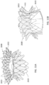
- FIGS 1-3 show an exemplary mitral valve prosthesis 10 in an expanded configuration after an expandable anchor and struts have been secured together.
- the portion of the replacement valve shown in Figure 1 may be referred to as an anchor subassembly, which includes an expandable anchor 1 and struts 5, but excludes leaflets and any skirts that may be incorporated into the final replacement valve.
- Expandable anchor 1 includes an atrial anchor 2, a ventricular anchor 4, and a central portion 3 therebetween.
- atrial anchor 2 is configured and adapted to be disposed on an atrial side of a mitral valve orifice
- ventricular anchor 4 is configured and adapted to be disposed on a ventricle side of the mitral valve orifice.
- expandable anchor 1 may be implanted so that atrial anchor 2 as shown is positioned on the ventricle side and ventricular anchor 4 is positioned on the atrial side.
- the anchor subassembly and/or struts can be made of wire, such as a metal wire, such as nitinol.
- Three struts 5 are secured to the anchor subassembly 1, and in this embodiment are secured to central portion 3, and at least a portion of struts 5 are disposed radially inward relative to central portion 3. Struts 5 are extending, or pointing, towards ventricular anchor 4 and away from atrial anchor 2.
- Radially inner surfaces of the expandable anchor and the struts define central opening 6, which is radially within the expandable anchor.
- the radially inner surfaces of central portion 3 substantially define the perimeter of central opening 6.
- Replacement leaflets which are not shown in Figure 1 for clarity, are secured to struts 5 and are disposed at least partially in central opening 6, and are configured to control blood flow therethrough.
- Atrial anchor 2 includes overlapping arches 32 extending around the perimeter of the anchor 2.
- Ventricular anchor 4 includes a plurality of arches 42 that extend from the central portion towards the ventricular end.
- a plurality of spaces 49 extend between adjacent arches 42, the configurations and sizes of which are defined by the configuration of adjacent arches 42, are configured to advantageously allow the sub-valvular structures, such as chords, to slide between adjacent arches 42 when the ventricular anchor is expanded on the ventricular side of the mitral valve annulus.
- the arch 32, 42 tips are rounded, or curved (as opposed to abrupt or sharp) to avoid damaging the tissue when implanted.
- Atrial anchor 2 and ventricular anchor 4 extend radially outward from central portion 3, and are considered to flare outward relative to central portion 4. Atrial anchor 2 and ventricular anchor 4 can also be considered flanged relative to central portion 3.
- the flared configuration of atrial and ventricular anchors 2 and 4 relative to central portion 3 is described in the context of a side view of the expandable anchor, as can be seen in Figure 2 (which illustrates leaflets secured to struts).
- one or more of the flared anchors are orthogonal to a longitudinal axis "LA" (illustrated in Figure 2 ) passing through central opening 6.
- the flared anchor portions have a smooth curve radially outward.
- the two anchors and the central portion define a general "C” or “U” shape in a side view of the expandable anchor.
- a “C” or “U” configuration is not limited to symmetrical configurations, however, as there can be slight deviation from a true "U” and still be considered to be U-shaped.
- the expandable anchor could define a "C” configuration, but one of the atrial and ventricular anchors could have a tighter curvature than the other anchor.
- the atrial and ventricular anchors are slightly curved inward towards the central portion at their respective ends.
- atrial anchor 2 and ventricular anchor 4 are substantially parallel to one another, such as exactly parallel to one another.
- the configuration of the flared anchors creates a substantially constant radius of curvature (i.e., a semi-circle) so that stress across anchors 2 and 4, and central portion 4 is balanced, thereby reducing fatigue or wear at any one point along the prosthesis.
- the flared configuration of the two anchors and the central portion define a general hour-glass shape in a side view of the expandable anchor (see, e.g., FIGS. 6F and 6G ). That is, the anchor portions can be flared outwards relative to the central portion and then curved or bent to point at least partially back in the axial direction.
- an hour glass configuration is not limited to symmetrical configuration.
- the expanded anchor 1 (not including the struts) has a length "L" (see Figure 2 , measured from the atrial end to the ventricular end, parallel to the longitudinal axis LA) of 6-12mm, such as 6-11mm, 6-10mm, 6-9mm, 7-11 mm, 8-10mm, 6 mm, 7mm, 8mm, 9mm, 10mm, 1 1mm, and 12mm.
- the length of the expanded prosthesis, including the struts (“LS" as shown in Figure 2 ), has a length of 16-20mm, such as 17-19mm, 16mm, 17mm, 18mm, 19mm, and 20mm with the struts.
- the expanded anchor has an expanded diameter ("D" in Figure 2 ) of about 35 mm to about 75 mm, such as about 45 mm to about 65 mm.
- the device is configured to be collapsed to a collapsed configuration in which it has a collapsed diameter D of 7mm to 12mm (i.e., the prosthesis can be collapsed down to fit within a 21-36 French catheter).
- the central opening 6 diameter is between 20 mm and 45 mm, such as between 25 mm and 40 mm, such as between 28 mm and 38 mm.
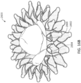
- the central opening diameter refers to the greatest linear dimension between points on the central portion, when viewed in an end view such as Figure 10A .
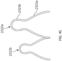
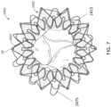
- one or both of the atrial and ventricular anchors 2302, 2304 of an expandable anchor of a replacement valve 2300 can include petals or extensions 2322a,b (only two are labeled for clarity) that are pear-shaped. That is, each extension 2322a,b can included two bulbous or rounded portions 2323a, 2323b.
- the radial innermost rounded portion 2323a can have a greater diameter than the radial outermost portion 2323b.
- the radial innermost rounded portion 2323a can be approximately 5-6mm in diameter while the radial outermost portion 2323b can be approximately 2-3mm in diameter.
- the pear-shaped extensions 2322a can advantageously provide sufficient grabbing force while providing a large-diameter blunt radial edge to reduce the chances of tissue damage.
- the extensions 2322a,b can have varying radial lengths.
- the anchor can include alternating longer extensions 2322a and shorter extensions 2322b around the circumference.
- the longer extensions 23222a for example, can have a length that is 1-3mm longer than a length of the shorter extensions 2322b.
- Having varying lengths can advantageously allow the extensions 2322a, 2322b to be cut out of a single tube or piece of material while still providing a large-diameter blunt radial edge.
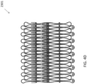
- Figure 4D shows a pattern for the expandable anchor 2301 cut out of a flat piece of material (which would then be rolled to form the anchor 2301).
- the atrial side includes double hooks therein for attachment to a delivery system, which will be described further below.
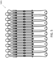
- Figure 5 shows a similar pattern for an expandable anchor 5301 cut out of a flat piece of material.
- the expandable anchor 5301 includes alternating pear-shaped extensions only on the ventricular side of the anchor 5301.
- the atrial side can include overlapping extensions that are substantially semicircular in shape, as shown in Figures 2 and 7 .
- the anchor with the pear-shaped extensions can be used on both the ventricular and atrial side.
- the anchor with the pear-shaped extensions can be used only on the atrial side.
- the pear-shaped extensions can be arranged in an overlapping fashion.
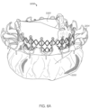
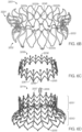
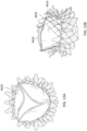
- FIGS. 6A-6G show another embodiment of a replacement valve 3200 including an atrial anchor 3202 and ventricular anchor 3204.
- the atrial and ventricular anchors 3202 extend radially outwards relative to the central portion 3203.
- the extensions 3222a,b of the atrial anchor and of the distal anchor are both pear-shaped and of alternating lengths, as described above with respect to valve 2300.
- the expandable anchor 3201 (including atrial anchor 2302, ventricular anchor 3204, and central portion 3203) forms a substantially hour-glass shape when viewed from the side, as can best be seen in Figures 6F and 6G ). Referring to FIG.
- the atrial anchor 3202 extends radially outwards at an angle ⁇ (relative an axis 3297 parallel to an axis of the plane of the annulus (perpendicular to the central longitudinal axis 3299)) of between 20 and 30 degrees, such as approximately 25 degrees.
- the tips of extensions 3222a,b of the atrial anchor are then bent or curved such that they point substantially in the atrial direction when implanted.
- the ventricular anchor 3204 extends radially outwards at an angle B (relative an axis 3298 parallel to an axis of the plane of the annulus (perpendicular to the central longitudinal axis 3299)) of between 5 and 20 degrees, such as approximately 10 degrees.
- the tips of extensions 3222b of the ventricular anchor are bent or curved such that they point at least partially in the ventricular direction. Moreover, the tips of the ventricular anchor 3222b continue curving at least partially radially inwards.
- the radius of curvature R of the tips of the ventricular anchor 3204 can be approximately 0.1 inches to 0.2 inches, such as 1/8 inches. Having the tips extensions 3222b of the ventricular anchor 3204 curve around to point radially inwards advantageously keeps the tips from getting caught on material, such as cords, in the ventricle during implantation. Further, having the tips extensions 3222a of the atrial anchor point substantially in the atrial direction advantageously provides a funnel to enhance flow of blood from the atrium to the ventricle (i.e., without interrupting the flow or providing pockets for the blood to pool therein).
- one or more of the anchors can have holes, eyelets, or other attachments mechanisms therein to allow a delivery device to attach thereto to control placement of the replacement valve.
- Exemplary delivery devices and methods are described in International Patent Application filed May 13, 2016, titled “CARDIAC VALVE DELIVERY DEVICES AND SYSTEMS,” the entirety of which is incorporated by reference herein.
- one or more of the anchors can include double eyelet hooks 3224 positioned in the distal tip of the extension 3222a of the atrial anchor 3202.
- the eyelets 3224 advantageously allow tethers from the delivery device to hold the atrial loops in a retracted position.
- the outer radial positioning of the eyelets 3224 can advantageously allow the tethers to pull the loops tightly into the sheath. Further, the double eyelet hooks can advantageously make it easy for an operator to loop the tether therethrough (as shown in FIG. 6E ).
- Eyelet 24 is a full circle that allows a suture to be passed therethrough.
- the eyelets 24 are positioned at the peak or furthest radial position of the extensions 2422 on the atrial anchor 2402.
- the suture 2475 looping around the circumference of the anchor 2402 and through the eyelets 24 can help prevent the atrial anchor 2402 from flaring outwards during delivery.
- the eyelets can be only on the extensions of the atrial anchor. In other embodiments, the eyelets can be only or additionally on extensions of the ventricular anchor. As shown in Figures 6E and 7 , the eyelets can be positioned along every other extension around the circumferential direction (such as only one of the overlapping frames, as shown in Figure 7 ). In other embodiments, the eyelets can be positioned on every extension of the atrial or ventricular anchors.
- the expandable anchors described herein can further include one or more apertures or holes configured for coupling attachment of various pieces of the valve.
- the expandable anchor 3201 can include a plurality of apertures 3246 therein configured to allow attachment via a coupler, such a rivet, to other sections of the valve, as described further below.
- the prostheses herein also include struts or a strut frame, to which the replacement leaflets are attached for controlling blood flow through the valve.
- the leaflets can be constructed of biomaterials, such as bovine or porcine pericardium, or polymer materials.
- valves described herein can thus include a separate annular strut frame coupled to a radially inner portion of the central portion (i.e., within the central portion).
- the annular strut frame may distribute forces more evenly over the central portion of the expandable anchor and may reduce the likelihood of undesirable central portion deformation once implanted.
- annular strut frame is an additional layer of material secured to the radially inner portion of the central portion, which reinforces and stabilizes the central portion when implanted. Additionally, by creating a coupling between the struts and the central portion (as opposed to having a solid portion of material that can provide additional stability), the flexibility of the coupling allows for relative movement of the struts during collapse of the device. This can reduce stresses on the device as it is collapsed, allowing for a smaller delivery profile, which as discussed herein can be important for delivery, such as a transseptal approach.
- the term annular in this context does not require a perfect annulus.
- the struts can either be integral to the strut frame or they can be separate components that are secured to the strut frame during manufacturing.
- FIG 8 is a perspective view illustrating an exemplary annular strut frame 1000.
- Strut frame 1000 includes frame portion 1002 and plurality of struts 1004.
- Struts 1004 extend further distally (i.e., in the ventricular direction) than frame portion 1002, and are configured to be secured to replacement leaflets as described herein.
- the strut frame 1000 has a ventricular end 1006 and an atrial end 1008.
- Strut portion 1002 includes a plurality of arches, which define peaks 1012 and valleys 1014. In this embodiment there are six strut frame arches, with two between adjacent struts 1004.
- Struts 1004 have an arch configuration defined by first leg 1020 and second leg 1022, each of which has a plurality of suture apertures 1018 therein.
- Struts 1004 each also have first and second extensions 1024 and 1026 extending away from legs 1020 and 1022 and towards atrial end 1008. Extensions 1024 and 1026 may also be considered part of the frame portion rather than the struts.
- Replacement leaflets are secured to struts 1004 at holes 1018 (e.g., by suturing).
- the strut frame also includes a plurality of apertures 1010 near the atrial end 1008, which are used to secure the annular strut frame to the central portion of the expandable anchor. The apertures are located at valleys 1014 in the frame portion.
- the annular strut frame is positioned radially within the central portion so that each of apertures 1010 is aligned with an aperture in the central portion, such as apertures 36.
- a coupler e.g., rivet
- a coupler is then advanced through the aligned apertures and one side of the coupler is then plastically deformed to secure the annular strut frame to the central portion.
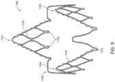
- FIG 9 illustrates an exemplary annular strut frame 1100.
- Strut frame 1100 includes three struts 1104 and frame portion 1102, which in this embodiment includes one arch between adjacent struts 1104.
- there is one coupling aperture 1010 within each strut in this embodiment there are two apertures 1110 within each strut 1104.
- Strut frame 1100 is coupled to a central portion by aligning apertures 1110 with apertures in the central portion, such as aperture 36, and then extending a coupler through each set of aligned apertures, and plastically deforming each coupler to secure the central portion to the annular strut frame at the locations of the couplings.
- FIGS 8 and 9 illustrate exemplary strut frames in their expanded configurations, when the rest of the expandable anchor (e.g., ventricular anchor, central portion, and atrial anchor) is also in an expanded configuration.
- Strut frames 19 and 20 can be secured to, and considered part of, any of the expandable anchors herein.
- the strut frame is cut from a tubular element, then expanded, and set in the expanded configuration using shape setting techniques described herein or otherwise known.
- the frame is cut from a 10 mm diameter tube, then expanded to an expanded configuration of about 32 mm (as shown in Figure 19 ), and set in the expanded configuration.
- the strut frames herein are .25 mm to about .45 mm thick, such as about .35 mm thick.
- the annular strut frame can be cut from a flat sheet and rolled up and secured together (examples of which are described above), or it can be cut from a tubular structure.
- Figures 8 and 9 illustrate exemplary annular, or cylindrical, strut frames can be disposed radially within the central portion of the expandable anchor.
- the central portion and the strut frame can be thought of as creating a composite cylinder when they are coupled together.
- the composite cylinder is thicker than each of the central portion and strut frame individually.
- Each of the central portion and strut frame is, however, relatively thin and can flex with respect to the other component. The relative flexibility can make it easier to collapse into a delivery configuration. If the composite region were a single material with a thickness equivalent to the combined thickness of the central portion and strut frame, that modified region may not be able to collapse sufficiently to meet, for example, size constraints without overstraining.
- the central portion and strut frame acting as a composite structure will not overstrain when collapsed into a collapsed configuration since the central portion and strut frame can flex independently.
- the composite central portion and strut frame also, when the expandable anchor expands, has a thickness greater than each component individually, thus providing an increased thickness that may be needed to resist torqueing and other forces on the central portion when implanted.
- the composite central portion and cylindrical strut frame thus enables collapsing as needed without overstraining, as well as provides a thickness to the central region that resists torqueing and deformation due to forces acting on the expandable anchor when implanted.
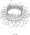
- FIGS 10A-E illustrate another exemplary annular or cylindrical strut frame 2500 that can be disposed radially within the central portion of the expandable anchor.
- strut frame 2500 can include a frame portion 2502 at the atrial end 2508 and a plurality of struts 2504, such as three struts 2504, at the ventricular end 2506. While the frame portion 2502 can extend substantially around the entire valve, the struts 2504 can extend at discrete locations about the valve. For example, the midpoint or center of each of the struts 2504 can be positioned approximately 120° away from one another.
- the entire frame 2500 can be made of a plurality of substantially diamond-shaped sub-features 2551 arranged in a pattern.
- the diamond sub-features 2551 can advantageously provide structural support to the strut frame 2500 and can be substantially resistant to deformation when circumferential and/or axial forces are placed on the strut frame 2500.
- the atrial-most tips 2553 of the strut frame 2500 can be rounded or blunt to prevent damage to the tissue when implanted.
- the atrial tips 2553 of the strut frame can be flared radially outwards relative to the rest of the strut frame 2500, which can remain substantially cylindrical.
- the angle of the bend can be between 25 degrees and 30 degrees relative to a plane of the annulus (i.e., 60-65 degrees relative to the central vertical axis of the annulus).
- the atrial trips can substantially conform to the angle of the atrial anchor relative to the central portion.
- a similarly flared structure can be seen in the strut frame 2415 of Figure 7 .
- the struts 2504 can each be substantially triangular in shape with blunt tips formed from three substantially aligned diamond sub-features (labeled as 2551a,b,c,d on Figure 25B).
- the middle diamond sub-feature 2551b of each strut 2504 can include one or more eyelets 2555 formed as a sewing attachment point for the leaflets.
- one or more of the diamond sub-features 2551 can include eyelets 2557 for attachment of the leaflets.
- the strut frame 2500 can further include apertures 2510 that can be used as rivet holes for attachment to the anchor frame.
- the apertures 2510 can be positioned, for example, between the proximal-most diamond sub-features 2551 of the strut frame 2500.
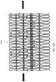
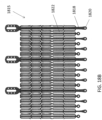
- Figure 10D shows the same strut frame 2500 in a two-dimensional un-stretched configuration.
- the two-dimensional version can be stretched linearly (in the direction shown by the arrows on Figure 30), and the atrial end 2408 can be bent.
- the strut frame 2500 can be cut out of a single piece of material, such as a tube or a flat sheet.
- the strut frame 2500 can be approximately 12-15mm high and 27-32mm in diameter.
- the radial flare of the tips 2633 at the atrial end 2608 of the strut frame 2615 can allow the atrial end 2608 to sit substantially flush with the atrial anchor 2602.
- the tips 2633 can remain unattached to the atrial anchor 2602 in order to allow for ease of collapse.
- the atrial tips 3133 of the strut frame 3100 can be axially aligned with the extensions 3122 of the atrial anchor 3102. That is, the midline of each tip 3133 can align with the midline of each extension 3122.
- the strut frame 3100 can be attached to the anchor 3100, such as a rivet extending between apertures 2510 (see Figures 10A-10D ) and apertures formed in the central portion of the anchor.
- the atrial tips 3133 substantially conform to the angle of the atrial anchor 3102, forming a continuous or smooth funnel from the proximal end to the distal end.
- the smooth funnel can advantageously ensure that blood flowing therethrough will flow continuously without catching or pooling within portions of the device, thereby preventing the formation of blood clots.
- the strut frame 3100 can be positioned such substantially all of the struts 3104 extend distally past the ventricular anchor 3104.
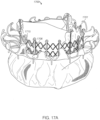
- the strut frame 3215 includes a substantially cylindrical ventricular portion 3251 and a flared atrial portion 3253 extending at least partially radially away from the cylindrical ventricular portion 3251.
- the flared atrial portion forms an angle of approximately 25-30 degrees relative to a plane of the annulus (i.e., 60-65 degrees relative to the central vertical or longitudinal axis of the annulus).
- the atrial tips 3255 of the flared atrial portion curve back to point substantially in the axial direction (similar to the atrial anchor 3201).
- the flares and atrial tips of each will be substantially flush with one another.
- the strut frame 3205 includes a plurality of zig-zag circumferential members extending around the circumference of the frame and a plurality of linear members extending from the ventricular end to the atrial end. Further, a plurality of eyelet apertures 3257 are positioned at the ventricular side. The eyelet apertures can be used to connect the strut frame 3215 to the anchor assembly 3201, such as via couplers or rivets.
- the strut frame 3205 can include a suture woven circumferentially around the strut frame 3205 (such as through the zig-zag members), similar to as shown in Figure 7 .
- the suture can advantageously help maintain the shape of the strut frame 3205 during delivery (e.g., help prevent flaring) so as to maintain low stress on the leaflets during delivery.
- the strut frame 3215 further includes ovoid attachment features 3205 at the ventricular end of the frame 3215 (attached leaflets 3220 are shown in FIG. 6A ).
- the ovoid attachment features 3205 include a plurality of sutures holes therein for attachment of the leaflets.
- the ovoid shape can advantageously distribute stress evenly at the highest stress point of the leaflets.
- other portions of the leaflets can be sewn directly to the zig-zag and/or features of the strut frame.
- Strut frame 4615 includes one or more eyelets 4655 extending along the strut frame for sewing attachment of the leaflets 4620.
- the strut frames described herein can be configured to mechanically isolate the leaflets from the anchoring mechanism of the implant, thereby isolating the leaflets from stresses caused by movement of the annulus and/or the non-uniform shape of the annulus.
- the strut frame can have greater radial strength or rigidity than the anchor, thereby allowing the strut frame to retain its substantially cylindrical shape while the anchor conforms to surrounding anatomy.
- the strut frame deflection under full pressure loading results in a 1-2mm decrease in diameter.
- a central member or suspension can extend between the strut frame and the anchor frame.
- the central member can help provide further mechanical isolation of the leaflets relative to the anchoring members. That is, it is generally desirable that the strut frame to which the leaflets are attached maintain its intended expanded configuration. If the strut frame deforms too extensively, the orientation and/or alignment of the replacement leaflets that are secured to the strut frame can be compromised, which may prevent proper leaflet coaptation during use.
- the central member described herein prevents or at least minimizes movement or deformation of the expandable anchor from being translated to the strut frame. Alternatively stated, the central member reduces deformation of the strut frame in response to deformation of the expandable anchor.
- the central member can thus be thought of as a shock system between the expandable anchor and the strut frame (or the replacement leaflets).
- the central member In response to deformation of expandable anchor, the central member is configured to deform while preventing or minimizing deformation of the strut frame.
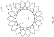
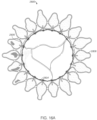
- Figure 14 illustrates a mitral valve prosthesis 300 (viewed from a ventricular side) that includes a central member 306 in addition to the expandable anchor 302 and strut frame 304.
- the expandable anchor 302 is coupled to the central member 306, and the central member 306 is coupled to strut frame 304.
- Strut frame 304 defines central opening 310.
- the expandable anchor 302 can be any of the expandable anchors described above or incorporated by reference herein.
- strut frame 304 can be any of the strut frames described above.
- the strut frame shown in Figure 14 is replaced with discrete struts. The replacement leaflets that are secured to strut frame 304 are not shown in Figure 14 for clarity.
- the central member 306 can include a plurality of connectors or spring elements 308 extending between the anchor 302 and the strut frame 308.
- the spring elements 308 can be resilient members that together act as a suspension for the strut frame 304 and can compress or extend when force is applied thereto, but can return to their former shape when released. The spring elements 308 can thus be used to absorb forces placed on the anchoring member to prevent or reduce forces on the strut frame (and thus the leaflets).
- the spring elements 308 can include leaflet springs (as shown in Figure 14 ), S-springs (as shown in Figure 15A ), V-springs (as shown in Figure 15B , circle springs (as shown in Figure 15C ), or any other type of spring elements, such as helical springs. In some embodiments, all of the spring elements 308 are the same type of spring, while in other embodiments, different types of springs can be used.
- central member 306 includes eighteen individual or discrete spring elements 308.
- the spring elements 308 are secured to expandable anchor 302 at a radially outer end and to strut frame 304 at a radially inner end.
- Springs 308 can be secured to expandable anchor 302 and to strut frame 304, for example, via rivets, such as is described herein.
- each spring element 308 can include two apertures 3912 therein at opposite ends of the spring.
- the apertures 3912 can allow for attachment of the spring elements 308 to the strut frame and the anchor through rivets or other attachment mechanisms.
- the spring elements 308 can be secured to expandable anchor 302 along the central portion of expandable anchor 302, which is the radially innermost portion of expandable anchor 302.
- the implant can have four spring elements 308 disposed about every 90 degrees around the strut frame 304, or three spring elements 308, or even two spring elements 308.
- the implant can have, for example, inclusively, between 1 and 25 springs, such as between 1 and 20 spring elements, such as between 2 and 20 spring elements.
- different spring elements 308 of the suspension 306 can have different spring constants. The spring constants can be between 20g/mm and 100g/mm.
- FIGS 16A-C show a mitral valve prosthesis 2800 including an outer expandable frame 2804, a central member 2806 (in the form of a plurality of individual spring elements), an annular strut frame 2802, and leaflets.
- the radially inner strut frame 2804 is radially offset from the outer expandable frame 2802 due to the central member or 2806.
- the central member can have a continuous annular configuration, such as form a continuous spring 2908, as shown in Figure 15D , configured to extend around the entire circumference of the strut frame 304 (i.e., between the strut frame 304 and the anchor 302).
- the continuous spring can have a plurality of bends that act as springs and a plurality of apertures 2911, 2933 arranged in an alternating configuration such that neighboring apertures 2911, 2933 attach to the strut frame and the anchor assembly.
- the continuous spring can be attached such that at least one bed extends between the strut frame and the anchor frame, providing an offset (and additional spring element) between the two.
- FIG. 6C similarly shows a central member 3206 having a continuous annular configuration.
- the central member 3206 includes a plurality of linear posts 3261 extending from the atrial end to the ventricular end and a plurality of zig-zag circumferential members 3266.
- the ventricular end of the central member 3206 has a smaller diameter (which can be, e.g., 25-30mm, such as 27mm) than the dimeter of the atrial end (which can be e.g., 30-35mm, such as 32mm).
- Each post 3261 inches a ventricular eyelet or aperture 3263 and an atrial eyelet or aperture 3265.
- the apertures ventricular 3263 can be configured to connect with apertures 3257 on the strut frame while the atrial apertures 3266 can be configured to connect to apertures 3246 on the anchor assembly 3201.
- the central member 3206 thus angles inward from the anchor assembly 3201 to the strut frame 3215 so as to connect the two. As shown in Figure 6A , the central member 3206 can connect the anchor assembly 3201 with the strut frame 3215 and can act as a suspension to allow relative movement between the two.
- Figures 17A-D show a valve prosthesis 1700 with anchor assembly 1701 that is similar to the prosthesis of FIGS. 6A-6F , but three of the linear posts 1761 of the central member 1706 extend further in the ventricular direction than the rest, and sutures holes on the ovoid leaflet attachment mechanism 1705 are moved further proximally, thereby ensuring that the riveting attachment of the central member 1706 to the strut frame 1715 does not interfere with the attachment of the leaflets to the strut frame 1715.
- the expandable anchor, central member or suspension, and strut frame optionally have different spring constants, which is generally a measure of how stiff and strong a material is.
- the strut frame can have the greatest spring constant, while the central member or suspension can have the lowest spring constant to allow it be deformed most easily.
- the expandable anchor can have a spring constant in between that of the strut frame and central member. Strut frame can have the greatest spring constant to resist deformation as much as possible.
- the central members described herein advantageously prevent or minimize torqueing or twisting of the strut frame in response to torqueing of the expandable anchor. Further, the central member can allow for radial movement while preventing or minimizing axial movement.
- the elements e.g., linear posts or individual suspension members
- connecting the strut frame to the expandable anchor may have cross sections that are thin in the radial direction and thick in the axial and rotational directions.
- the central member can help maintain the axial position of the components (strut frame and anchor) during packaging.
- the central members described herein can allow the prosthesis to be implanted in patients with varying anatomies and accommodate for those differences while preventing the strut frame from deforming too extensively.
- the mitral valve can be dilated quite extensively in some patients, and thus there may be a desire to have some variability built into the prosthesis.
- the elements of the central member can compensate for that variability.
- the same strut frame size can be used with anchors of inner and outer diameters, and the central member can compensate for the dimensional difference.
- a strut frame having a diameter of 27mm can be used in an anchor having a dimeter of 32-38mm.
- a strut frame of 29mm can be used with an anchor have a diameter of 38-44mm in diameter.
- the spring length can be increased to support the valve as the anchor diameter increases.
- the skirt can be configured to cover the gap between the anchor frame and the strut frame.
- the anchor assembly and/or the strut assembly can have integrated suspension units attached thereto.
- the valve 1800 includes strut frame 1815 and anchor assembly 1801.
- the linear posts 1818 of the strut frame 1815 extend past the circumferential zig-zag features 1822 of the strut frame 1815 on the atrial side.
- the posts each include eyelet holes 1820 at the atrial end thereof.
- the eyelet holes 1820 are configured to line up with eyelet holes 1857 (see FIG. 18C ) on the atrial tips of the anchor assembly 1801 to provide for coupling attachment, such as through rivets.
- the atrial anchor in this embodiment has petals of alternating lengths (as best shown in FIG. 18C ), so the extensions of the posts 1818 have alternating lengths to accommodate (as best shown in FIG. 18B ). Similar to other embodiments described herein, the atrial side of the strut frame 1806 can flare outwards (see FIG. 18A ). The posts 1818 can thus be used to attach the strut frame 1815 to the anchor assembly 1801. Further, because the posts 1801 have extensions in the atrial direction, those extensions can act as springs, such as leaf springs, to provide a suspensions between the main body of the strut frame 1815 and the anchor assembly 1801.
- FIGS. 19A -19C Another example of a valve 1900 with an integrated assembly is shown in FIGS. 19A -19C.
- the posts 1918 are attached to the central portion of the anchor assembly 1901 rather than to the atrial petals. Because the posts 1918 are attached to the central portion (thereby providing suspension), the atrial petals of the atrial anchor 1902 can be more flexible, and overlapping petals can be used (as shown in FIG. 19A ).
- FIGS. 20A-20C Another valve assembly 3700 with the strut frame 3715 attached to the atrial anchor 3703 is shown in FIGS. 20A-20C . That is, the atrial anchor 3702 can include apertures 3710 (see Figure 20C ) configured to attach to apertures 3780 (see Figure 20B ) of the strut frame 3715.
- the alignment of the anchor 3701 and the strut frame 3715 is shown in Figure 20A .
- the valves 1900 and 2700 thus include suspensions characteristics that are provided by offsetting the rivet attachment points towards the atrial side, thereby creating a cantilever beam supporting the leaflet strut coming from the atrium.
- Any of the embodiments described hereinabove can further include hooks configured to enhance attachment of the implant to the tissue.
- the hooks 3732 can be positioned in the valleys between extensions 3722 of the ventricular anchor 3704, i.e., can extend from the radial inner-most part of the ventricular anchor 3204.
- the hooks 3632 can additionally or alternatively be positioned in the valleys between extensions of the atrial anchor.
- hooks 3232b can extend from the central portion 3203, such as point in radially outwards and/or slightly in the ventricular direction. Hooks 3222a can also extend from the ventricular anchor in the valleys and point substantially in the atrial direction.
- the hooks can be configured to embed into annulus tissue, thereby helping to resist the pressure build-up on the ventricular side of the aorta.
- ventricular anchor, central anchor, and atrial anchor can all be made from the same piece, i.e., be integral with one another.
- a manufacturing step could include cutting a strut and an expandable anchor from different pieces of starting material, and securing them together, and they would be considered non-integral.
- the coupling of the two components when one or more components are secured together, can be made so that the two components are rigidly secured at the coupling, or so that the two components can move to some degree at the location of the coupling of the two components (e.g., pivotable).
- Rivets as used herein are an example of a coupler, as that term or derivatives thereof is used herein.
- the locations where components are secured to one another may be referred to as a coupling herein.
- Coupling also refers to the two components that are secured together.
- Riveting as used herein is an example of a method that plastically deforms a coupler to secure two or more components together at a coupling.
- the rivets can be inserted through the apertures described herein and the ends can then be plastically deformed using known riveting techniques to secure the two or more components together.
- the rivets can be made of a suitable implantable material, such as platinum, platinum-iridium alloy, tantalum, nickel-titanium alloy, or titanium and titanium alloys, such as titanium 6-4eli.
- the riveted coupling can be such that one or more rivets are not tightened all the way down to the secured components, which allows for hinging of the coupling, if desired.
- Rivets used for hinging may be made of materials suitable for implantable bearing surfaces such as Nitronic 60 alloy, or nitinol.
- Hinge pins can be coated with low-friction, high-durability coatings, such as diamond-like coating, or titanium nitride.
- rivets and hinges can provide an additional benefit of preventing cracking that can occur as single pieces of material flex and move. Additionally, rivets and hinges can provide various degrees of relevant movement between portions of the valve, which can allow the valve to be collapsed into a smaller delivery profile for delivery. The relative movement can also provide increased flexibility of the valve during delivery. Rivets can also allow for a variation in the relative orientation of the riveted components. In some embodiments, rivets provide increased flexibility that allows for greater trackability during delivery and better self-centering of the anchor against cardiac tissue (i.e., provides advantages for both access and conformability to the anatomy).
- the couplings herein also allow different section of material with different physical properties to be secured to one another.
- atrial anchors can be made thinner than the central portion and/or ventricular anchors.
- valve prostheses described herein can include a fabric cover and/or skirt or one or more portions of the device.
- FIG. 6A shows a skirt covering the anchor assembly.
- valve prostheses have been shown without leaflets for clarity. It is to be understood that each of the embodiments described herein can included replacement leaflets attached thereto.
- valve features or structural details of any device embodiment described herein can be incorporated or combined with any of the other embodiments herein.
- the central members or suspensions described herein are not limited in use with the expandable anchors and strut frames in the specific embodiment, but can be replaced with any of the features described in any other embodiment.
- the ventricular anchor can be deployed first in a cardiac chamber, such as the ventricle, and retracted to a seated position against the valve orifice, such as the mitral valve orifice. Then the center portion and atrial anchor portion may be deployed in another cardiac chamber, such as the atrium, wherein the expansion and reconfiguration of the atrial anchor and the central portion sandwiches the valve orifice securely between the anchors that have been deployed on either side of the annulus.
- a cardiac chamber such as the ventricle
- the center portion and atrial anchor portion may be deployed in another cardiac chamber, such as the atrium, wherein the expansion and reconfiguration of the atrial anchor and the central portion sandwiches the valve orifice securely between the anchors that have been deployed on either side of the annulus.
- references to a structure or feature that is disposed "adjacent" another feature may have portions that overlap or underlie the adjacent feature.
- the device may be otherwise oriented (rotated 90 degrees or at other orientations) and the spatially relative descriptors used herein interpreted accordingly.
- the terms “upwardly”, “downwardly”, “vertical”, “horizontal” and the like are used herein for the purpose of explanation only unless specifically indicated otherwise.
- first and second may be used herein to describe various features/elements (including steps), these features/elements should not be limited by these terms, unless the context indicates otherwise. These terms may be used to distinguish one feature/element from another feature/element. Thus, a first feature/element discussed below could be termed a second feature/element, and similarly, a second feature/element discussed below could be termed a first feature/element without departing from the teachings of the present invention.
Abstract
A replacement mitral valve includes an anchor assembly including a ventricular anchor, an annular central portion, and an atrial anchor, an annular strut frame disposed radially within the anchor assembly, a central annular member between the anchor assembly and annular strut frame, and a plurality of replacement leaflets secured to the annular strut frame. The anchor assembly is configured to compress native cardiac tissue between the ventricular anchor and the atrial anchor. The central annular member is connected to both the anchor assembly and the annular strut frame so as to connect the anchor assembly to the annular strut frame.
Description
- This application claims priority to
U.S. Provisional Application No. 62/161,743, titled "REPLACEMENT MITRAL VALVES," and filed May 14, 2015 U.S. Provisional Patent Application No. 62/259,565, titled "REPLACEMENT MITRAL VALVES," and filed November 24, 2015 - This application may be related to
U.S. Patent Application No. 14/170,388, filed January 31, 2014 U.S. Patent No. 8,870,948 , andU.S. Patent Application No. 14/677,320, filed April 2, 2015 - All publications and patent applications mentioned in this specification are herein incorporated by reference to the same extent as if each individual publication or patent application was specifically and individually indicated to be incorporated by reference.
- The mitral valve lies between the left atrium and the left ventricle of the heart. Various diseases can affect the function of the mitral valve, including degenerative mitral valve disease and mitral valve prolapse. These diseases can cause mitral stenosis, in which the valve fails to open fully and thereby obstructs blood flow, and/or mitral insufficiency, in which the mitral valve is incompetent and blood flows passively in the wrong direction.
- Many patients with heart disease, such as problems with the mitral valve, are intolerant of the trauma associated with open-heart surgery. Age or advanced illness may have impaired the patient's ability to recover from the injury of an open-heart procedure. Additionally, the high costs associated with open-heart surgery and extra-corporeal perfusion can make such procedures prohibitive.
- Patients in need of cardiac valve repair or cardiac valve replacement can be served by minimally invasive surgical techniques. In many minimally invasive procedures, small devices are manipulated within the patient's body under visualization from a live imaging source like ultrasound, fluoroscopy, or endoscopy. Minimally invasive cardiac procedures are inherently less traumatic than open procedures and may be performed without extra-corporeal perfusion, which carries a significant risk of procedural complications.
- Minimally invasive aortic valve replacement devices, such as the Medtronic Corevalve or the Edwards Sapien, deliver aortic valve prostheses through small tubes which may be positioned within the heart through the aorta via the femoral artery or through the apex of the heart. However, the mitral valve differs from the aortic valve in that the shape and anatomy immediately surrounding the valve varies greatly from one side of the valve to the other. Moreover, current cardiac valve prostheses are not designed to function effectively within the mitral valve. Further, current cardiac valve prostheses delivered via a minimally invasive device are often difficult to place correctly within the native valve, difficult to match in size to the native valve, and difficult to retrieve and replace if initially placed incorrectly.
- These and other deficiencies in existing approaches are described herein.
- In general, in one embodiment, a replacement mitral valve includes an anchor assembly including a ventricular anchor, an annular central portion, and an atrial anchor, an annular strut frame disposed radially within the anchor assembly, a central annular member between the anchor assembly and annular strut frame, and a plurality of replacement leaflets secured to the annular strut frame. The anchor assembly is configured to compress native cardiac tissue between the ventricular anchor and the atrial anchor. The central annular member is connected to both the anchor assembly and the annular strut frame so as to connect the anchor assembly to the annular strut frame.
- This and other embodiments can include one or more of the following features. A ventricular end of the central annular member can have a smaller diameter than a diameter of the atrial end of the central annular member. The diameter of the ventricular end can be between 25mm and 30mm, and the diameter of the atrial end is between 30mm and 35mm. The central annular member can include a plurality of linear posts extending from an atrial end to a ventricular end and a plurality of zig-zag circumferential members extending circumferentially therearound. The central annular member can have a lower spring constant than the strut frame. The strut frame can have a higher spring constant than the anchor assembly. The central annular member can include a suspension. The central annular member and the anchor assembly can be connected together with couplers. The central annular member and the annular strut frame can be connected together with couplers. The central annular member can be configured to minimize deformation of replacement leaflet alignment in response to deformation of an expandable anchor. The device can be configured to self-expand from a constrained configuration to an expanded configuration. The device can be configured to foreshorten upon expansion of the atrial anchor, ventricular anchor, and central portion from the constrained configuration to the expanded configuration.
- In general, in one embodiment, a replacement mitral valve includes an anchor assembly comprising a ventricular anchor, an annular central portion, and an atrial anchor, an annular strut frame disposed radially within the anchor assembly, a suspension connecting the anchor assembly to the annular strut frame, and a plurality of replacement leaflets secured to the annular strut frame. The anchor assembly is configured to compress native cardiac tissue between the ventricular anchor and the atrial anchor.
- This and other embodiments can include one or more of the following features. The suspension can have a lower spring constant than the strut frame. The strut frame can have a higher spring constant than the anchor assembly. The suspension can include a plurality of springs. The springs can be leaf springs. The suspension and the anchor assembly can be connected together with couplers. The suspension and the annular strut frame can be connected together with couplers. The suspension can be configured to minimize deformation of replacement leaflet alignment in response to deformation of an expandable anchor. The device can be configured to self-expand from a constrained configuration to an expanded configuration. The device can be configured to foreshorten upon expansion of the atrial anchor, ventricular anchor, and central portion from the constrained configuration to the expanded configuration.
- In general, in one embodiment, a prosthetic mitral valve includes an anchor assembly including an atrial anchor, a ventricular anchor, and a central portion therebetween, and a plurality of replacement leaflets coupled with the anchor assembly. The atrial anchor or the ventricular anchor includes an annular frame having plurality of pear-shaped extensions connected together. The anchor assembly is configured to self-expand from a constrained configuration to an expanded configuration in which the ventricular anchor and the atrial anchor are flared radially outward relative to the central portion. The anchor assembly in the expanded configuration is configured to compress native cardiac tissue between the ventricular anchor and the atrial anchor.
- This and other embodiments can include one or more of the following features. The annular frame can be substantially circular. The device can be configured to foreshorten upon expansion of the atrial anchor, ventricular anchor, and central portion from the constrained configuration to the expanded configuration. The atrial anchor and the ventricular anchor can each have a diameter in the expanded configuration that is greater than a diameter of the central portion in the expanded configuration. The atrial anchor and the ventricular can include an annular frame having a plurality of pear-shaped extensions connected together. At least two of the plurality of pear-shaped extensions can have different lengths from one another. Each of the plurality of pear-shaped extensions can include an inner rounded portion and an outer rounded portion. The inner rounded portion can have a smaller diameter than a diameter of the outer rounded portion. The diameter of the inner rounded portion can be between 2mm and 3mm, and the diameter of the outer rounded portion can be between 5mm and 6mm. The atrial anchor, ventricular anchor, and central portion can all be integral with one another. The prosthetic mitral valve can further include an annular strut frame secured radially within the anchor assembly. The annular strut frame can be configured to support the plurality of replacement leaflets. When the anchor assembly is in the expanded configuration, extensions on the ventricular anchor can curve around to point at least partially radially inwards. When the anchor assembly is in the expanded configuration, extensions of the atrial anchor point can be substantially in the atrial direction.
- In general, in one embodiment, a prosthetic mitral valve includes an anchor assembly including an atrial anchor, a ventricular anchor, and a central portion therebetween, and a plurality of replacement leaflets coupled with the anchor assembly. The atrial anchor or the ventricular anchor includes an annular frame having plurality of extensions connected together, wherein there are at least two extensions of differing radial lengths. The anchor assembly is configured to self-expand from a constrained configuration to an expanded configuration in which the ventricular anchor and the atrial anchor are flared radially outward relative to the central portion. The anchor assembly in the expanded configuration is configured to compress native cardiac tissue between the ventricular anchor and the atrial anchor.
- This and other embodiments can include one or more of the following features. The annular frame can be substantially circular. The device can be configured to foreshorten upon expansion of the atrial anchor, ventricular anchor, and central portion from the constrained configuration to the expanded configuration. The atrial anchor and the ventricular anchor can each have a diameter in the expanded configuration that is greater than a diameter of the central portion in the expanded configuration. The atrial anchor or the ventricular anchor can include a plurality of pear-shaped extensions connected together. The atrial anchor, ventricular anchor, and central portion can all be integral with one another. The prosthetic mitral valve can further include an annular strut frame secured radially within the anchor assembly. The annular strut frame can be configured to support the plurality of replacement leaflets. When the anchor assembly is in the expanded configuration, extensions on the ventricular anchor can curve around to point at least partially radially inwards. When the anchor assembly is in the expanded configuration, extensions of the atrial anchor can point substantially in the atrial direction.
- At least one extension can have a radial length that is between 1mm and 3mm longer than another extension. The plurality of extensions can include a plurality of first extensions having a first radial length and a plurality of second extensions having a second radial length. The first and second extensions can be arranged in an alternating pattern around the annular frame.
- In general, in one embodiment, a prosthetic mitral valve includes an anchor assembly including an atrial anchor, a ventricular anchor, and a central portion therebetween, and a plurality of replacement leaflets coupled with the anchor assembly. The ventricular anchor includes an annular frame having plurality of extensions connected together. The anchor assembly is configured to self-expand from a constrained configuration to an expanded configuration in which the ventricular anchor and the atrial anchor are flared radially outward relative to the central portion and ends of the extensions on the ventricular anchor curve around to point at least partially radially inwards. The anchor assembly in the expanded configuration is configured to compress native cardiac tissue between the ventricular anchor and the atrial anchor.
- This and other embodiments can include one or more of the following features. The annular frame can be substantially circular. The device can be configured to foreshorten upon expansion of the atrial anchor, ventricular anchor, and central portion from the constrained configuration to the expanded configuration. The atrial anchor and the ventricular anchor each have a diameter in the expanded configuration that is greater than a diameter of the central portion in the expanded configuration. The atrial anchor or the ventricular anchor includes a plurality of pear-shaped extensions connected together. The atrial anchor, ventricular anchor, and central portion can all be integral with one another. The prosthetic mitral valve can further include an annular strut frame secured radially within the anchor assembly. The annular strut frame can be configured to support the plurality of replacement leaflets. When the anchor assembly is in the expanded configuration, extensions of the atrial anchor can point substantially in the atrial direction. At least two of the plurality of pear-shaped extensions can have different lengths from one another. A radius of curvature formed by the curved ends of the extensions of the ventricular anchor can be between approximately 0.1" and 0.2."
- In general in one embodiment, a prosthetic mitral valve includes an anchor assembly including an atrial anchor, a ventricular anchor, and a central portion therebetween, and a plurality of replacement leaflets coupled with the anchor assembly. The atrial anchor includes an annular frame having plurality of extensions connected together. The anchor assembly is configured to self-expand from a constrained configuration to an expanded configuration in which the ventricular anchor and the atrial anchor are flared radially outward relative to the central portion and ends of the extensions on the atrial anchor point substantially in the atrial direction. The anchor assembly in the expanded configuration is configured to compress native cardiac tissue between the ventricular anchor and the atrial anchor.
- This and other embodiments can include one or more of the following features. The annular frame can be substantially circular. The device can be configured to foreshorten upon expansion of the atrial anchor, ventricular anchor, and central portion from the constrained configuration to the expanded configuration. The atrial anchor and the ventricular anchor can each have a diameter in the expanded configuration that is greater than a diameter of the central portion in the expanded configuration. The atrial anchor or the ventricular anchor can include a plurality of pear-shaped extensions connected together. The atrial anchor, ventricular anchor, and central portion can all be integral with one another. The prosthetic mitral valve can further include an annular strut frame secured radially within the anchor assembly. The annular strut frame can be configured to support the plurality of replacement leaflets. When the anchor assembly is in the expanded configuration, extensions on the ventricular anchor can curve around to point at least partially radially inwards. At least two of the plurality of pear-shaped extensions can have different lengths from one another.
- In general, in one embodiment, a replacement mitral valve includes an anchor assembly including a ventricular anchor, an annular central portion, and an atrial anchor, an annular strut frame disposed radially within the anchor assembly, and a plurality of replacement leaflets secured to the annular strut frame. The anchor assembly is configured to expand from a constrained configuration to an expanded configuration in which the ventricular anchor and the atrial anchor are flared radially outward relative to the central portion. The anchor assembly in the expanded configuration is configured to compress native cardiac tissue between the ventricular anchor and the atrial anchor. The annular strut frame is flared radially outward to form a funnel shape on an atrial side of the strut frame.
- This and other embodiment can include one or more of the following features. The replacement mitral valve can further include a plurality of ovoid strut attachment mechanisms extending from the annular strut frame. The ovoid strut attachment mechanisms can be configured for sewing attachment of the replacement leaflets. The annular strut frame can be attached to the anchor assembly with a plurality of couplers. The plurality of couplers can be rivets. The annular strut frame can be attached to the anchor assembly through a central annular member. The annular strut frame can be attached to the anchor assembly through a suspension. The atrial anchor can further include a flared atrial portion, wherein the flared atrial portion of the atrial anchor and the flare of the annular strut frame can be configured to substantially conform to one another. The strut frame can flare at an angle of approximately 60-65 degrees relative to a central axis of the mitral valve.
- In general, in one embodiment, a replacement mitral valve includes an anchor assembly including a ventricular anchor, an annular central portion, and an atrial anchor, an annular strut frame disposed radially within the anchor assembly, and a plurality of replacement leaflets secured to the annular strut frame. The anchor assembly is configured to expand from a constrained configuration to an expanded configuration in which the ventricular anchor and the atrial anchor are flared radially outward relative to the central portion. The anchor assembly in the expanded configuration is configured to compress native cardiac tissue between the ventricular anchor and the atrial anchor. The annular strut frame has a plurality of rivet holes at a ventricular end of the strut frame configured for attachment to the anchor assembly.
- This and other embodiments can include one or more of the following features. The replacement mitral valve can further include a plurality of ovoid strut attachment mechanisms extending from the annular strut frame. The ovoid strut attachment mechanisms can be configured for sewing attachment of the replacement leaflets. The annular strut frame can be attached to the anchor assembly with a plurality of couplers. Each coupler can extend through a hole of the plurality of holes. The plurality of couplers can be rivets. The anchor assembly can further include a plurality of holes. A coupler can extend through each of the holes of the anchor assembly for attachment to the annular strut frame. The annular strut frame can be attached to the anchor assembly through a central annular member. The annular strut frame can be attached to the anchor assembly through a suspension.
- In general, in one embodiment, a replacement mitral valve includes an anchor assembly comprising a ventricular anchor, an annular central portion, and an atrial anchor, an annular strut frame disposed radially within the anchor assembly, and a plurality of replacement leaflets secured to the annular strut frame. The anchor assembly is configured to expand from a constrained configuration to an expanded configuration in which the ventricular anchor and the atrial anchor are flared radially outward relative to the central portion. The anchor assembly in the expanded configuration is configured to compress native cardiac tissue between the ventricular anchor and the atrial anchor. The annular strut frame includes a suture extending around an entire circumference of the annular strut frame to prevent flaring of one end of the annular strut frame relative to another during delivery of the replacement valve.
- In general, in one embodiment, a prosthetic mitral valve includes an anchor assembly including an atrial anchor, a ventricular anchor, and a central portion therebetween, and a plurality of replacement leaflets coupled with the anchor assembly. The atrial anchor or the ventricular anchor includes an annular frame having plurality of peaks and valleys extending around the circumference. A hook is positioned in one or more of the valleys configured to engage tissue. The anchor assembly is configured to self-expand from a constrained configuration to an expanded configuration in which the ventricular anchor and the atrial anchor are flared radially outward relative to the central portion. The anchor assembly in the expanded configuration is configured to compress native cardiac tissue between the ventricular anchor and the atrial anchor.
- In general, in one embodiment, a prosthetic mitral valve includes an anchor assembly including an atrial anchor, a ventricular anchor, and a central portion therebetween, and a plurality of replacement leaflets coupled with the anchor assembly. A plurality of hooks extend from the central portion configured to engage tissue. The anchor assembly is configured to self-expand from a constrained configuration to an expanded configuration in which the ventricular anchor and the atrial anchor are flared radially outward relative to the central portion. The anchor assembly in the expanded configuration is configured to compress native cardiac tissue between the ventricular anchor and the atrial anchor.
- The novel features of the invention are set forth with particularity in the claims that follow. A better understanding of the features and advantages of the present invention will be obtained by reference to the following detailed description that sets forth illustrative embodiments, in which the principles of the invention are utilized, and the accompanying drawings of which:
-
Figure 1 shows a portion of an embodiment of a valve prosthesis in an expanded configuration. -
Figure 2 is a side view illustrating the prosthesis ofFigure 1 including leaflets. -
Figure 3 illustrates an integral central portion and ventricular anchor after being cut from a sheet of material. -
Figure 4A is a top view of another embodiment of a valve prosthesis. -
Figure 4B is a side view of another embodiment of a valve prosthesis. -
Figure 4C is a close-up showing two anchor extensions side by side. -
Figure 4D shows a flattened anchor assembly. -
Figure 5 shows another embodiment of a flattened anchor assembly. -
Figure 6A shows another embodiment of a valve prosthesis. -
Figure 6B shows the anchor assembly of the valve prosthesis ofFigure 6A . -
Figure 6C shows a central member of the valve prosthesis ofFigure 6A . -
Figure 6D shows a strut frame of the valve prosthesis ofFigure 6A . -
Figure 6E shows a close-up of the anchor assembly ofFigure 6B . -
Figure 6F shows a side view of the anchor assembly ofFigure 6B . -
Figure 6G is a cross-section of the valve prosthesis ofFigure 6A without the skirt or leaflets attached thereto. -
Figure 7 shows a top view of another embodiment of a valve prosthesis. -
Figure 8 shows an embodiment of a strut frame. -
Figure 9 shows another embodiment of a strut frame. -
Figures 10A-10D show various view of a strut frame. -
Figure 10E shows the strut frame ofFigures 10A-10D flattened. -
Figures 11A-11B shows another embodiment of a valve prosthesis. -
Figures 12A-12B show another embodiment of a valve prosthesis. -
Figures 13A-13B show another embodiment of a valve prosthesis. -
Figure 14 shows a top view of a valve prosthesis having spring members between the strut frame and the anchor assembly. -
Figures 15A-15D show various embodiments of spring members. -
Figure 16A-16C show another embodiment of a valve prosthesis. -
Figure 17A shows another embodiment of a valve prosthesis. -
Figure 17B shows the anchor assembly of the valve prosthesis ofFigure 17A . -
Figure 17C shows the central member of the valve prosthesis ofFigure 17A . -
Figure 17D shows the strut frame of the valve prosthesis ofFigure 17A . -
Figure 18A shows another embodiment of a valve prosthesis. -
Figure 18B shows a flattened strut frame of the valve prosthesis ofFigure 18A . -
Figure 18C shows a flattened anchor assembly of the valve prosthesis ofFigure 18A . -
Figures 19A-19B shows another embodiment of a valve prosthesis. -
Figure 20A shows a flattened and overlaid anchor assembly and strut frame. -
Figure 20B shows the strut frame ofFigure 20A . -
Figure 20C shows the anchor assembly ofFigure 20A . - This disclosure includes replacement heart valves (also referred herein as prosthetic heart valves), methods of manufacturing replacement heart valves, including subassemblies thereof, and methods of using replacement heart valves. This disclosure describes the prostheses in the context of replacement mitral valves, but it is conceivable that the prostheses herein can be used or modified to be used as other replacement heart valves. In some embodiments, the replacement heart valves are self-orienting (at least on one side) replacement mitral valves configured to be delivered using minimally invasive techniques.
- The replacement heart valves herein include an expandable anchor that includes an atrial anchor (e.g., configured to be placed on an atrial side of a mitral valve annulus), a ventricular anchor (e.g., configured to be placed on a ventricular side of a mitral valve annulus), and a central portion axially between the atrial and ventricular anchors. The expandable anchor is adapted to be collapsed towards a collapsed delivery configuration, and is adapted to expand towards an expandable configuration. The replacement heart valves also include a plurality of struts or strut frame secured to at least one of the central portion, the ventricular anchor, or the atrial anchor for securing a plurality of replacement leaflets thereto. The struts or strut frame can be considered part of the expandable anchor, and in embodiments herein are configured to deform as the rest of the expandable anchor is collapsed. It may be possible to incorporate struts that are not deformable, but which are still secured to the expandable anchor. These types of struts may not be considered part of the expandable anchor but are secured to the expandable anchor. The struts extend distally, that is, towards the ventricular anchor. In the context of replacement mitral valves, the "distal" end of the replacement valve refers to the end of the replacement valve that is to be positioned on the ventricular side of the annulus, while "proximal" end refers to the end of the replacement valve that is to be positioned on the atrial side of the annulus. "Distally" in the context of trans-atrial delivery can be used to refer to a location closer to the left ventricle than the left atrium, while "proximally" is generally used to refer to a location closer to the left atrium than the left ventricle.
- In some embodiments, the expandable anchor is adapted to completely self-expand, and in some embodiments it is configured to be partially self-expanding and partially expand by non-self-expanding influences (e.g., a balloon). The expandable anchors can be made of (or partly made of) a super elastic material such as nitinol.
- In methods of use, the prostheses described herein can be delivered to a cardiac valve orifice, such as the mitral valve, by using minimally invasive techniques to access the cardiac valve. Access routes and procedures are known, such as making small incisions in the patient's body and passing the prosthesis through the apex of the heart to, for example, a mitral valve. An additional exemplary access route includes delivering the valve through the venous system and into the left atrium via a transseptal puncture. A transseptal approach can impart size limitations on the delivery and thus the delivery profile of the replacement heart valve. Additionally, a transseptal approach can also impart certain flexibility requirements on the replacement heart valve. The replacement heart valves herein are configured to be collapsed into a delivery configuration so they can fit within a delivery device. The replacement heart valves can be delivered to the treatment site within the delivery device and then deployed from the delivery device. If necessary, the replacement valves can be repositioned, re-sheathed (partially or completely) if necessary, and then re-deployed.
- Replacement heart valves herein are configured to be secured in the native valve orifice by sandwiching the cardiac orifice between ventricular and atrial anchors, which are larger in diameter than the valve orifice, and by applying a radial force from the center portion outward against the cardiac orifice. Additional engagement between the prostheses and cardiac tissue can be added with wire hooks extending from the valve prostheses.
-
Figures 1-3 show an exemplarymitral valve prosthesis 10 in an expanded configuration after an expandable anchor and struts have been secured together. The portion of the replacement valve shown inFigure 1 may be referred to as an anchor subassembly, which includes anexpandable anchor 1 and struts 5, but excludes leaflets and any skirts that may be incorporated into the final replacement valve.Expandable anchor 1 includes an atrial anchor 2, aventricular anchor 4, and acentral portion 3 therebetween. In this embodiment, atrial anchor 2 is configured and adapted to be disposed on an atrial side of a mitral valve orifice, andventricular anchor 4 is configured and adapted to be disposed on a ventricle side of the mitral valve orifice. In some uses, however,expandable anchor 1 may be implanted so that atrial anchor 2 as shown is positioned on the ventricle side andventricular anchor 4 is positioned on the atrial side. The anchor subassembly and/or struts can be made of wire, such as a metal wire, such as nitinol. - Three
struts 5 are secured to theanchor subassembly 1, and in this embodiment are secured tocentral portion 3, and at least a portion ofstruts 5 are disposed radially inward relative tocentral portion 3.Struts 5 are extending, or pointing, towardsventricular anchor 4 and away from atrial anchor 2. - Radially inner surfaces of the expandable anchor and the struts define
central opening 6, which is radially within the expandable anchor. The radially inner surfaces ofcentral portion 3 substantially define the perimeter ofcentral opening 6. Replacement leaflets, which are not shown inFigure 1 for clarity, are secured tostruts 5 and are disposed at least partially incentral opening 6, and are configured to control blood flow therethrough. - In this embodiment, atrial anchor 2 includes overlapping
arches 32 extending around the perimeter of the anchor 2. Ventricularanchor 4 includes a plurality ofarches 42 that extend from the central portion towards the ventricular end. A plurality of spaces 49 (seeFIG. 3 ) extend betweenadjacent arches 42, the configurations and sizes of which are defined by the configuration ofadjacent arches 42, are configured to advantageously allow the sub-valvular structures, such as chords, to slide betweenadjacent arches 42 when the ventricular anchor is expanded on the ventricular side of the mitral valve annulus. The arch 32, 42 tips are rounded, or curved (as opposed to abrupt or sharp) to avoid damaging the tissue when implanted. - In the expanded configuration shown in
Figure 1 (which is also an "as-manufactured" configuration), atrial anchor 2 andventricular anchor 4 extend radially outward fromcentral portion 3, and are considered to flare outward relative tocentral portion 4. Atrial anchor 2 andventricular anchor 4 can also be considered flanged relative tocentral portion 3. The flared configuration of atrial andventricular anchors 2 and 4 relative tocentral portion 3 is described in the context of a side view of the expandable anchor, as can be seen inFigure 2 (which illustrates leaflets secured to struts). - In some embodiments, one or more of the flared anchors are orthogonal to a longitudinal axis "LA" (illustrated in
Figure 2 ) passing throughcentral opening 6. In some embodiments, the flared anchor portions have a smooth curve radially outward. In some flared configuration the two anchors and the central portion define a general "C" or "U" shape in a side view of the expandable anchor. A "C" or "U" configuration is not limited to symmetrical configurations, however, as there can be slight deviation from a true "U" and still be considered to be U-shaped. For example, the expandable anchor could define a "C" configuration, but one of the atrial and ventricular anchors could have a tighter curvature than the other anchor. When the anchor portions are flared and create a "C" shaped configuration, the atrial and ventricular anchors are slightly curved inward towards the central portion at their respective ends. In some embodiments, atrial anchor 2 andventricular anchor 4 are substantially parallel to one another, such as exactly parallel to one another. In some embodiments the configuration of the flared anchors creates a substantially constant radius of curvature (i.e., a semi-circle) so that stress acrossanchors 2 and 4, andcentral portion 4 is balanced, thereby reducing fatigue or wear at any one point along the prosthesis. In other embodiments, the flared configuration of the two anchors and the central portion define a general hour-glass shape in a side view of the expandable anchor (see, e.g.,FIGS. 6F and6G ). That is, the anchor portions can be flared outwards relative to the central portion and then curved or bent to point at least partially back in the axial direction. Again, an hour glass configuration is not limited to symmetrical configuration. - In some embodiments the expanded anchor 1 (not including the struts) has a length "L" (see
Figure 2 , measured from the atrial end to the ventricular end, parallel to the longitudinal axis LA) of 6-12mm, such as 6-11mm, 6-10mm, 6-9mm, 7-11 mm, 8-10mm, 6 mm, 7mm, 8mm, 9mm, 10mm, 1 1mm, and 12mm. In some embodiments the length of the expanded prosthesis, including the struts ("LS" as shown inFigure 2 ), has a length of 16-20mm, such as 17-19mm, 16mm, 17mm, 18mm, 19mm, and 20mm with the struts. In some embodiments, the expanded anchor has an expanded diameter ("D" inFigure 2 ) of about 35 mm to about 75 mm, such as about 45 mm to about 65 mm. In some of those embodiments the device is configured to be collapsed to a collapsed configuration in which it has a collapsed diameter D of 7mm to 12mm (i.e., the prosthesis can be collapsed down to fit within a 21-36 French catheter). In some embodiments thecentral opening 6 diameter is between 20 mm and 45 mm, such as between 25 mm and 40 mm, such as between 28 mm and 38 mm. In embodiments in whichcentral opening 6 is not a perfect circle, the central opening diameter refers to the greatest linear dimension between points on the central portion, when viewed in an end view such asFigure 10A . - Referring to
Figures 4A-4C , in some embodiments, one or both of the atrial andventricular anchors replacement valve 2300 can include petals orextensions 2322a,b (only two are labeled for clarity) that are pear-shaped. That is, eachextension 2322a,b can included two bulbous orrounded portions rounded portion 2323a can have a greater diameter than the radialoutermost portion 2323b. The radial innermostrounded portion 2323a can be approximately 5-6mm in diameter while the radialoutermost portion 2323b can be approximately 2-3mm in diameter. The pear-shapedextensions 2322a can advantageously provide sufficient grabbing force while providing a large-diameter blunt radial edge to reduce the chances of tissue damage. - Referring still to
Figures 4A-4C , in some embodiments, theextensions 2322a,b can have varying radial lengths. For example, the anchor can include alternatinglonger extensions 2322a andshorter extensions 2322b around the circumference. The longer extensions 23222a, for example, can have a length that is 1-3mm longer than a length of theshorter extensions 2322b. Having varying lengths can advantageously allow theextensions Figure 4D shows a pattern for theexpandable anchor 2301 cut out of a flat piece of material (which would then be rolled to form the anchor 2301). In thispattern 2301, the atrial side includes double hooks therein for attachment to a delivery system, which will be described further below.Figure 5 shows a similar pattern for anexpandable anchor 5301 cut out of a flat piece of material. Theexpandable anchor 5301 includes alternating pear-shaped extensions only on the ventricular side of theanchor 5301. - In some embodiments where the alternating pear-shaped extensions are only on the ventricular side, the atrial side can include overlapping extensions that are substantially semicircular in shape, as shown in
Figures 2 and7 . In other embodiments, the anchor with the pear-shaped extensions can be used on both the ventricular and atrial side. In yet other embodiments, the anchor with the pear-shaped extensions can be used only on the atrial side. Moreover in some embodiments, the pear-shaped extensions can be arranged in an overlapping fashion. -
Figures 6A-6G show another embodiment of areplacement valve 3200 including anatrial anchor 3202 andventricular anchor 3204. The atrial andventricular anchors 3202 extend radially outwards relative to thecentral portion 3203. Theextensions 3222a,b of the atrial anchor and of the distal anchor are both pear-shaped and of alternating lengths, as described above with respect tovalve 2300. Further, the expandable anchor 3201 (includingatrial anchor 2302,ventricular anchor 3204, and central portion 3203) forms a substantially hour-glass shape when viewed from the side, as can best be seen inFigures 6F and6G ). Referring toFIG. 6G , theatrial anchor 3202 extends radially outwards at an angle α (relative anaxis 3297 parallel to an axis of the plane of the annulus (perpendicular to the central longitudinal axis 3299)) of between 20 and 30 degrees, such as approximately 25 degrees. The tips ofextensions 3222a,b of the atrial anchor are then bent or curved such that they point substantially in the atrial direction when implanted. Likewise, theventricular anchor 3204 extends radially outwards at an angle B (relative anaxis 3298 parallel to an axis of the plane of the annulus (perpendicular to the central longitudinal axis 3299)) of between 5 and 20 degrees, such as approximately 10 degrees. Further, the tips ofextensions 3222b of the ventricular anchor are bent or curved such that they point at least partially in the ventricular direction. Moreover, the tips of theventricular anchor 3222b continue curving at least partially radially inwards. The radius of curvature R of the tips of theventricular anchor 3204 can be approximately 0.1 inches to 0.2 inches, such as 1/8 inches. Having thetips extensions 3222b of theventricular anchor 3204 curve around to point radially inwards advantageously keeps the tips from getting caught on material, such as cords, in the ventricle during implantation. Further, having thetips extensions 3222a of the atrial anchor point substantially in the atrial direction advantageously provides a funnel to enhance flow of blood from the atrium to the ventricle (i.e., without interrupting the flow or providing pockets for the blood to pool therein). - In some embodiments, one or more of the anchors can have holes, eyelets, or other attachments mechanisms therein to allow a delivery device to attach thereto to control placement of the replacement valve. Exemplary delivery devices and methods are described in International Patent Application filed May 13, 2016, titled "CARDIAC VALVE DELIVERY DEVICES AND SYSTEMS," the entirety of which is incorporated by reference herein. Referring to
Figures 6B and6E , one or more of the anchors (here atrial anchor 3202) can include double eyelet hooks 3224 positioned in the distal tip of theextension 3222a of theatrial anchor 3202. The eyelets 3224 advantageously allow tethers from the delivery device to hold the atrial loops in a retracted position. The outer radial positioning of the eyelets 3224 can advantageously allow the tethers to pull the loops tightly into the sheath. Further, the double eyelet hooks can advantageously make it easy for an operator to loop the tether therethrough (as shown inFIG. 6E ). - Another embodiment of an
eyelet 24 for delivery is shown inFigure 7 .Eyelet 24 is a full circle that allows a suture to be passed therethrough. Theeyelets 24 are positioned at the peak or furthest radial position of theextensions 2422 on theatrial anchor 2402. Thesuture 2475 looping around the circumference of theanchor 2402 and through theeyelets 24 can help prevent theatrial anchor 2402 from flaring outwards during delivery. - In some embodiments, the eyelets can be only on the extensions of the atrial anchor. In other embodiments, the eyelets can be only or additionally on extensions of the ventricular anchor. As shown in
Figures 6E and7 , the eyelets can be positioned along every other extension around the circumferential direction (such as only one of the overlapping frames, as shown inFigure 7 ). In other embodiments, the eyelets can be positioned on every extension of the atrial or ventricular anchors. - The expandable anchors described herein can further include one or more apertures or holes configured for coupling attachment of various pieces of the valve. For example, referring to
Figure 6B , theexpandable anchor 3201 can include a plurality ofapertures 3246 therein configured to allow attachment via a coupler, such a rivet, to other sections of the valve, as described further below. - The prostheses herein also include struts or a strut frame, to which the replacement leaflets are attached for controlling blood flow through the valve. There can be three strut leaflets, which can form a pressure actuated valve that provides uni-directional flow occlusion when the prosthesis is implanted in the valve orifice. The leaflets can be constructed of biomaterials, such as bovine or porcine pericardium, or polymer materials.
- Some central portions herein or other portions of other replacement heart valves may be susceptible to undesirable deforming when implanted, such as due to movement during the heartbeat and/or in response to pressures in the heart. The valves described herein can thus include a separate annular strut frame coupled to a radially inner portion of the central portion (i.e., within the central portion). The annular strut frame may distribute forces more evenly over the central portion of the expandable anchor and may reduce the likelihood of undesirable central portion deformation once implanted.
- An annular strut frame is an additional layer of material secured to the radially inner portion of the central portion, which reinforces and stabilizes the central portion when implanted. Additionally, by creating a coupling between the struts and the central portion (as opposed to having a solid portion of material that can provide additional stability), the flexibility of the coupling allows for relative movement of the struts during collapse of the device. This can reduce stresses on the device as it is collapsed, allowing for a smaller delivery profile, which as discussed herein can be important for delivery, such as a transseptal approach. The term annular in this context does not require a perfect annulus.
- When the prosthesis includes a strut frame, the struts can either be integral to the strut frame or they can be separate components that are secured to the strut frame during manufacturing.
-
Figure 8 is a perspective view illustrating an exemplaryannular strut frame 1000.Strut frame 1000 includesframe portion 1002 and plurality ofstruts 1004.Struts 1004 extend further distally (i.e., in the ventricular direction) thanframe portion 1002, and are configured to be secured to replacement leaflets as described herein. Thestrut frame 1000 has aventricular end 1006 and anatrial end 1008.Strut portion 1002 includes a plurality of arches, which definepeaks 1012 andvalleys 1014. In this embodiment there are six strut frame arches, with two betweenadjacent struts 1004.Struts 1004 have an arch configuration defined byfirst leg 1020 andsecond leg 1022, each of which has a plurality ofsuture apertures 1018 therein.Struts 1004 each also have first andsecond extensions legs atrial end 1008.Extensions struts 1004 at holes 1018 (e.g., by suturing). The strut frame also includes a plurality ofapertures 1010 near theatrial end 1008, which are used to secure the annular strut frame to the central portion of the expandable anchor. The apertures are located atvalleys 1014 in the frame portion. In some embodiments the annular strut frame is positioned radially within the central portion so that each ofapertures 1010 is aligned with an aperture in the central portion, such asapertures 36. A coupler (e.g., rivet) is then advanced through the aligned apertures and one side of the coupler is then plastically deformed to secure the annular strut frame to the central portion. -
Figure 9 illustrates an exemplaryannular strut frame 1100.Strut frame 1100 includes threestruts 1104 andframe portion 1102, which in this embodiment includes one arch betweenadjacent struts 1104. Unlike the embodiment inFigure 8 , in which there is onecoupling aperture 1010 within each strut, in this embodiment there are twoapertures 1110 within eachstrut 1104. Just as in the embodiment inFigure 8 , there are also apertures at the ends of each leg of struts.Strut frame 1100 is coupled to a central portion by aligningapertures 1110 with apertures in the central portion, such asaperture 36, and then extending a coupler through each set of aligned apertures, and plastically deforming each coupler to secure the central portion to the annular strut frame at the locations of the couplings. -
Figures 8 and9 illustrate exemplary strut frames in their expanded configurations, when the rest of the expandable anchor (e.g., ventricular anchor, central portion, and atrial anchor) is also in an expanded configuration. Strut frames 19 and 20 can be secured to, and considered part of, any of the expandable anchors herein. - In an exemplary method of manufacturing, the strut frame is cut from a tubular element, then expanded, and set in the expanded configuration using shape setting techniques described herein or otherwise known. For example, in an exemplary embodiment, the frame is cut from a 10 mm diameter tube, then expanded to an expanded configuration of about 32 mm (as shown in
Figure 19 ), and set in the expanded configuration. In some exemplary embodiments the strut frames herein are .25 mm to about .45 mm thick, such as about .35 mm thick. - The annular strut frame can be cut from a flat sheet and rolled up and secured together (examples of which are described above), or it can be cut from a tubular structure.
-
Figures 8 and9 illustrate exemplary annular, or cylindrical, strut frames can be disposed radially within the central portion of the expandable anchor. The central portion and the strut frame can be thought of as creating a composite cylinder when they are coupled together. The composite cylinder is thicker than each of the central portion and strut frame individually. Each of the central portion and strut frame is, however, relatively thin and can flex with respect to the other component. The relative flexibility can make it easier to collapse into a delivery configuration. If the composite region were a single material with a thickness equivalent to the combined thickness of the central portion and strut frame, that modified region may not be able to collapse sufficiently to meet, for example, size constraints without overstraining. The central portion and strut frame acting as a composite structure will not overstrain when collapsed into a collapsed configuration since the central portion and strut frame can flex independently. The composite central portion and strut frame also, when the expandable anchor expands, has a thickness greater than each component individually, thus providing an increased thickness that may be needed to resist torqueing and other forces on the central portion when implanted. The composite central portion and cylindrical strut frame thus enables collapsing as needed without overstraining, as well as provides a thickness to the central region that resists torqueing and deformation due to forces acting on the expandable anchor when implanted. -
Figures 10A-E illustrate another exemplary annular orcylindrical strut frame 2500 that can be disposed radially within the central portion of the expandable anchor. As shown,strut frame 2500 can include aframe portion 2502 at theatrial end 2508 and a plurality ofstruts 2504, such as threestruts 2504, at theventricular end 2506. While theframe portion 2502 can extend substantially around the entire valve, thestruts 2504 can extend at discrete locations about the valve. For example, the midpoint or center of each of thestruts 2504 can be positioned approximately 120° away from one another. - The
entire frame 2500 can be made of a plurality of substantially diamond-shapedsub-features 2551 arranged in a pattern. The diamond sub-features 2551 can advantageously provide structural support to thestrut frame 2500 and can be substantially resistant to deformation when circumferential and/or axial forces are placed on thestrut frame 2500. - The
atrial-most tips 2553 of thestrut frame 2500 can be rounded or blunt to prevent damage to the tissue when implanted. Moreover, as shown inFigures 10A-D , theatrial tips 2553 of the strut frame can be flared radially outwards relative to the rest of thestrut frame 2500, which can remain substantially cylindrical. The angle of the bend can be between 25 degrees and 30 degrees relative to a plane of the annulus (i.e., 60-65 degrees relative to the central vertical axis of the annulus). Further, the atrial trips can substantially conform to the angle of the atrial anchor relative to the central portion. A similarly flared structure can be seen in thestrut frame 2415 ofFigure 7 . - Referring still to
Figures 10A-10D , thestruts 2504 can each be substantially triangular in shape with blunt tips formed from three substantially aligned diamond sub-features (labeled as 2551a,b,c,d on Figure 25B). The middle diamond sub-feature 2551b of eachstrut 2504 can include one ormore eyelets 2555 formed as a sewing attachment point for the leaflets. Likewise, one or more of thediamond sub-features 2551 can includeeyelets 2557 for attachment of the leaflets. - The
strut frame 2500 can further includeapertures 2510 that can be used as rivet holes for attachment to the anchor frame. Theapertures 2510 can be positioned, for example, between the proximal-most diamond sub-features 2551 of thestrut frame 2500. -
Figure 10D shows thesame strut frame 2500 in a two-dimensional un-stretched configuration. To form thestrut frame 2500 in the three-dimensional configuration shown in Figures 25A-25D, the two-dimensional version can be stretched linearly (in the direction shown by the arrows on Figure 30), and the atrial end 2408 can be bent. Advantageously, thestrut frame 2500 can be cut out of a single piece of material, such as a tube or a flat sheet. Thestrut frame 2500 can be approximately 12-15mm high and 27-32mm in diameter. - Referring to
Figures 11A-B , the radial flare of the tips 2633 at theatrial end 2608 of thestrut frame 2615 can allow theatrial end 2608 to sit substantially flush with theatrial anchor 2602. The tips 2633, however, can remain unattached to theatrial anchor 2602 in order to allow for ease of collapse. - In some embodiments, as shown best in
Figure 12A , theatrial tips 3133 of thestrut frame 3100 can be axially aligned with theextensions 3122 of theatrial anchor 3102. That is, the midline of eachtip 3133 can align with the midline of eachextension 3122. Thestrut frame 3100 can be attached to theanchor 3100, such as a rivet extending between apertures 2510 (seeFigures 10A-10D ) and apertures formed in the central portion of the anchor. Further, as shown inFigure 12B , theatrial tips 3133 substantially conform to the angle of theatrial anchor 3102, forming a continuous or smooth funnel from the proximal end to the distal end. The smooth funnel can advantageously ensure that blood flowing therethrough will flow continuously without catching or pooling within portions of the device, thereby preventing the formation of blood clots. Moreover, as further shown inFigure 12B , thestrut frame 3100 can be positioned such substantially all of thestruts 3104 extend distally past theventricular anchor 3104. - Another embodiment of a
strut frame 3215 is shown inFigure 6D . As shown inFigure 6D , thestrut frame 3215 includes a substantiallycylindrical ventricular portion 3251 and a flaredatrial portion 3253 extending at least partially radially away from thecylindrical ventricular portion 3251. The flared atrial portion forms an angle of approximately 25-30 degrees relative to a plane of the annulus (i.e., 60-65 degrees relative to the central vertical or longitudinal axis of the annulus). Further, in this embodiment, theatrial tips 3255 of the flared atrial portion curve back to point substantially in the axial direction (similar to the atrial anchor 3201). Thus, referring toFigure 6A , when placed within theatrial anchor 3201, the flares and atrial tips of each will be substantially flush with one another. - Referring to
Figure 6D , thestrut frame 3205 includes a plurality of zig-zag circumferential members extending around the circumference of the frame and a plurality of linear members extending from the ventricular end to the atrial end. Further, a plurality ofeyelet apertures 3257 are positioned at the ventricular side. The eyelet apertures can be used to connect thestrut frame 3215 to theanchor assembly 3201, such as via couplers or rivets. - In some embodiments, the
strut frame 3205 can include a suture woven circumferentially around the strut frame 3205 (such as through the zig-zag members), similar to as shown inFigure 7 . The suture can advantageously help maintain the shape of thestrut frame 3205 during delivery (e.g., help prevent flaring) so as to maintain low stress on the leaflets during delivery. - As shown in
Figure 6D , thestrut frame 3215 further includes ovoid attachment features 3205 at the ventricular end of the frame 3215 (attached leaflets 3220 are shown inFIG. 6A ). The ovoid attachment features 3205 include a plurality of sutures holes therein for attachment of the leaflets. The ovoid shape can advantageously distribute stress evenly at the highest stress point of the leaflets. In one embodiment, there can be three ovoid attachment features 3205 separated approximately 120 degrees around the circumference from one another. In this embodiment, other portions of the leaflets can be sewn directly to the zig-zag and/or features of the strut frame. - Another mechanism for attaching leaflets is shown in
FIGS. 13A-13B .Strut frame 4615 includes one ormore eyelets 4655 extending along the strut frame for sewing attachment of theleaflets 4620. - The strut frames described herein can be configured to mechanically isolate the leaflets from the anchoring mechanism of the implant, thereby isolating the leaflets from stresses caused by movement of the annulus and/or the non-uniform shape of the annulus. In any of the embodiments described herein, the strut frame can have greater radial strength or rigidity than the anchor, thereby allowing the strut frame to retain its substantially cylindrical shape while the anchor conforms to surrounding anatomy. In one embodiment, the strut frame deflection under full pressure loading results in a 1-2mm decrease in diameter.
- In some embodiments, a central member or suspension can extend between the strut frame and the anchor frame. The central member can help provide further mechanical isolation of the leaflets relative to the anchoring members. That is, it is generally desirable that the strut frame to which the leaflets are attached maintain its intended expanded configuration. If the strut frame deforms too extensively, the orientation and/or alignment of the replacement leaflets that are secured to the strut frame can be compromised, which may prevent proper leaflet coaptation during use. The central member described herein prevents or at least minimizes movement or deformation of the expandable anchor from being translated to the strut frame. Alternatively stated, the central member reduces deformation of the strut frame in response to deformation of the expandable anchor. The central member can thus be thought of as a shock system between the expandable anchor and the strut frame (or the replacement leaflets). In response to deformation of expandable anchor, the central member is configured to deform while preventing or minimizing deformation of the strut frame.
-
Figure 14 illustrates a mitral valve prosthesis 300 (viewed from a ventricular side) that includes acentral member 306 in addition to theexpandable anchor 302 andstrut frame 304. Theexpandable anchor 302 is coupled to thecentral member 306, and thecentral member 306 is coupled to strutframe 304.Strut frame 304 definescentral opening 310. Although shown as including non-overlapping pear-shaped petals or extensions, theexpandable anchor 302 can be any of the expandable anchors described above or incorporated by reference herein. Further,strut frame 304 can be any of the strut frames described above. Moreover, in some alternative embodiments, the strut frame shown inFigure 14 is replaced with discrete struts. The replacement leaflets that are secured to strutframe 304 are not shown inFigure 14 for clarity. - As shown in
Figure 14 , thecentral member 306 can include a plurality of connectors orspring elements 308 extending between theanchor 302 and thestrut frame 308. Thespring elements 308 can be resilient members that together act as a suspension for thestrut frame 304 and can compress or extend when force is applied thereto, but can return to their former shape when released. Thespring elements 308 can thus be used to absorb forces placed on the anchoring member to prevent or reduce forces on the strut frame (and thus the leaflets). Thespring elements 308 can include leaflet springs (as shown inFigure 14 ), S-springs (as shown inFigure 15A ), V-springs (as shown inFigure 15B , circle springs (as shown inFigure 15C ), or any other type of spring elements, such as helical springs. In some embodiments, all of thespring elements 308 are the same type of spring, while in other embodiments, different types of springs can be used. - In the exemplary embodiment in
Figure 14 ,central member 306 includes eighteen individual ordiscrete spring elements 308. Thespring elements 308 are secured toexpandable anchor 302 at a radially outer end and to strutframe 304 at a radially inner end.Springs 308 can be secured toexpandable anchor 302 and to strutframe 304, for example, via rivets, such as is described herein. As shown, inFigures 15A-15C eachspring element 308 can include two apertures 3912 therein at opposite ends of the spring. The apertures 3912 can allow for attachment of thespring elements 308 to the strut frame and the anchor through rivets or other attachment mechanisms. Thespring elements 308 can be secured toexpandable anchor 302 along the central portion ofexpandable anchor 302, which is the radially innermost portion ofexpandable anchor 302. - In other embodiments, there may be few or
more spring elements 308. For example, if the expandable anchor had a design different than shown inFigure 14 ,fewer spring elements 308 may be needed. Or, alternatively, the design inFigure 14 could have ninespring elements 308, leaving out every other spring element around thestrut frame 304. Alternatively, the implant can have fourspring elements 308 disposed about every 90 degrees around thestrut frame 304, or threespring elements 308, or even twospring elements 308. The implant can have, for example, inclusively, between 1 and 25 springs, such as between 1 and 20 spring elements, such as between 2 and 20 spring elements. In some embodiments,different spring elements 308 of thesuspension 306 can have different spring constants. The spring constants can be between 20g/mm and 100g/mm. -
Figures 16A-C show amitral valve prosthesis 2800 including an outerexpandable frame 2804, a central member 2806 (in the form of a plurality of individual spring elements), anannular strut frame 2802, and leaflets. As can be seen inFigures 16A-16C , the radiallyinner strut frame 2804 is radially offset from the outerexpandable frame 2802 due to the central member or 2806. - In some embodiments, the central member can have a continuous annular configuration, such as form a
continuous spring 2908, as shown inFigure 15D , configured to extend around the entire circumference of the strut frame 304 (i.e., between thestrut frame 304 and the anchor 302). The continuous spring can have a plurality of bends that act as springs and a plurality ofapertures neighboring apertures Figure 15D , the continuous spring can be attached such that at least one bed extends between the strut frame and the anchor frame, providing an offset (and additional spring element) between the two. -
Figure 6C similarly shows acentral member 3206 having a continuous annular configuration. Thecentral member 3206 includes a plurality oflinear posts 3261 extending from the atrial end to the ventricular end and a plurality of zig-zag circumferential members 3266. The ventricular end of thecentral member 3206 has a smaller diameter (which can be, e.g., 25-30mm, such as 27mm) than the dimeter of the atrial end (which can be e.g., 30-35mm, such as 32mm). Each post 3261 inches a ventricular eyelet or aperture 3263 and an atrial eyelet oraperture 3265. The apertures ventricular 3263 can be configured to connect withapertures 3257 on the strut frame while theatrial apertures 3266 can be configured to connect toapertures 3246 on theanchor assembly 3201. Thecentral member 3206 thus angles inward from theanchor assembly 3201 to thestrut frame 3215 so as to connect the two. As shown inFigure 6A , thecentral member 3206 can connect theanchor assembly 3201 with thestrut frame 3215 and can act as a suspension to allow relative movement between the two. -
Figures 17A-D show avalve prosthesis 1700 withanchor assembly 1701 that is similar to the prosthesis ofFIGS. 6A-6F , but three of thelinear posts 1761 of thecentral member 1706 extend further in the ventricular direction than the rest, and sutures holes on the ovoidleaflet attachment mechanism 1705 are moved further proximally, thereby ensuring that the riveting attachment of thecentral member 1706 to thestrut frame 1715 does not interfere with the attachment of the leaflets to thestrut frame 1715. - The expandable anchor, central member or suspension, and strut frame optionally have different spring constants, which is generally a measure of how stiff and strong a material is. For example, the strut frame can have the greatest spring constant, while the central member or suspension can have the lowest spring constant to allow it be deformed most easily. The expandable anchor can have a spring constant in between that of the strut frame and central member. Strut frame can have the greatest spring constant to resist deformation as much as possible.
- The central members described herein advantageously prevent or minimize torqueing or twisting of the strut frame in response to torqueing of the expandable anchor. Further, the central member can allow for radial movement while preventing or minimizing axial movement. For example, the elements (e.g., linear posts or individual suspension members) connecting the strut frame to the expandable anchor may have cross sections that are thin in the radial direction and thick in the axial and rotational directions. In some embodiments, the central member can help maintain the axial position of the components (strut frame and anchor) during packaging.
- Since there are mitral valve anatomical differences between patients, the central members described herein can allow the prosthesis to be implanted in patients with varying anatomies and accommodate for those differences while preventing the strut frame from deforming too extensively. For example, the mitral valve can be dilated quite extensively in some patients, and thus there may be a desire to have some variability built into the prosthesis. The elements of the central member can compensate for that variability. For example, the same strut frame size can be used with anchors of inner and outer diameters, and the central member can compensate for the dimensional difference. For example, a strut frame having a diameter of 27mm can be used in an anchor having a dimeter of 32-38mm. Likewise, a strut frame of 29mm can be used with an anchor have a diameter of 38-44mm in diameter. The spring length can be increased to support the valve as the anchor diameter increases. Further, the skirt can be configured to cover the gap between the anchor frame and the strut frame.
- In some embodiments, the anchor assembly and/or the strut assembly can have integrated suspension units attached thereto. For example, referring to
FIGS. 18A-18C , thevalve 1800 includesstrut frame 1815 andanchor assembly 1801. As shown inFIGS. 18A and 189B, thelinear posts 1818 of thestrut frame 1815 extend past the circumferential zig-zag features 1822 of thestrut frame 1815 on the atrial side. Further, the posts each includeeyelet holes 1820 at the atrial end thereof. The eyelet holes 1820 are configured to line up with eyelet holes 1857 (seeFIG. 18C ) on the atrial tips of theanchor assembly 1801 to provide for coupling attachment, such as through rivets. The atrial anchor in this embodiment has petals of alternating lengths (as best shown inFIG. 18C ), so the extensions of theposts 1818 have alternating lengths to accommodate (as best shown inFIG. 18B ). Similar to other embodiments described herein, the atrial side of the strut frame 1806 can flare outwards (seeFIG. 18A ). Theposts 1818 can thus be used to attach thestrut frame 1815 to theanchor assembly 1801. Further, because theposts 1801 have extensions in the atrial direction, those extensions can act as springs, such as leaf springs, to provide a suspensions between the main body of thestrut frame 1815 and theanchor assembly 1801. - Another example of a
valve 1900 with an integrated assembly is shown inFIGS. 19A -19C. In this embodiment, theposts 1918 are attached to the central portion of theanchor assembly 1901 rather than to the atrial petals. Because theposts 1918 are attached to the central portion (thereby providing suspension), the atrial petals of theatrial anchor 1902 can be more flexible, and overlapping petals can be used (as shown inFIG. 19A ). Anothervalve assembly 3700 with thestrut frame 3715 attached to the atrial anchor 3703 is shown inFIGS. 20A-20C . That is, theatrial anchor 3702 can include apertures 3710 (seeFigure 20C ) configured to attach to apertures 3780 (seeFigure 20B ) of thestrut frame 3715. The alignment of theanchor 3701 and thestrut frame 3715 is shown inFigure 20A . Thevalves 1900 and 2700 thus include suspensions characteristics that are provided by offsetting the rivet attachment points towards the atrial side, thereby creating a cantilever beam supporting the leaflet strut coming from the atrium. - Any of the embodiments described hereinabove can further include hooks configured to enhance attachment of the implant to the tissue.
- In one embodiment, as shown in
Figure 20C , the hooks 3732 can be positioned in the valleys between extensions 3722 of theventricular anchor 3704, i.e., can extend from the radial inner-most part of theventricular anchor 3204. In some embodiments, thehooks 3632 can additionally or alternatively be positioned in the valleys between extensions of the atrial anchor. Advantageously, by placing the hooks in the valley between the extensions, they do not drag on tissue during release and/or repositioning of the device. That is, by being positioned at the inner-most radial position, the hooks will not grab tissue until the atrial andventricular anchors - In another embodiment, as shown in
Figures 6B and6E , hooks 3232b can extend from thecentral portion 3203, such as point in radially outwards and/or slightly in the ventricular direction.Hooks 3222a can also extend from the ventricular anchor in the valleys and point substantially in the atrial direction. - The hooks can be configured to embed into annulus tissue, thereby helping to resist the pressure build-up on the ventricular side of the aorta.
- When two components are secured together during manufacturing, they are considered to be non-integral, or non-monolithic, components. Different portions of the expandable anchor that are made from the same starting material are considered to be integral, or monolithic. For example, the ventricular anchor, central anchor, and atrial anchor can all be made from the same piece, i.e., be integral with one another. In contrast, a manufacturing step could include cutting a strut and an expandable anchor from different pieces of starting material, and securing them together, and they would be considered non-integral. In some embodiments, when one or more components are secured together, the coupling of the two components can be made so that the two components are rigidly secured at the coupling, or so that the two components can move to some degree at the location of the coupling of the two components (e.g., pivotable).
- Rivets as used herein are an example of a coupler, as that term or derivatives thereof is used herein. The locations where components are secured to one another may be referred to as a coupling herein. Coupling also refers to the two components that are secured together. Riveting as used herein is an example of a method that plastically deforms a coupler to secure two or more components together at a coupling.
- The rivets can be inserted through the apertures described herein and the ends can then be plastically deformed using known riveting techniques to secure the two or more components together. The rivets can be made of a suitable implantable material, such as platinum, platinum-iridium alloy, tantalum, nickel-titanium alloy, or titanium and titanium alloys, such as titanium 6-4eli. In some embodiments, the riveted coupling can be such that one or more rivets are not tightened all the way down to the secured components, which allows for hinging of the coupling, if desired. Rivets used for hinging may be made of materials suitable for implantable bearing surfaces such as Nitronic 60 alloy, or nitinol. Hinge pins can be coated with low-friction, high-durability coatings, such as diamond-like coating, or titanium nitride.
- Use of rivets and hinges (as opposed to, for example, crimp tubes) can provide an additional benefit of preventing cracking that can occur as single pieces of material flex and move. Additionally, rivets and hinges can provide various degrees of relevant movement between portions of the valve, which can allow the valve to be collapsed into a smaller delivery profile for delivery. The relative movement can also provide increased flexibility of the valve during delivery. Rivets can also allow for a variation in the relative orientation of the riveted components. In some embodiments, rivets provide increased flexibility that allows for greater trackability during delivery and better self-centering of the anchor against cardiac tissue (i.e., provides advantages for both access and conformability to the anatomy).
- The couplings herein (e.g., riveting) also allow different section of material with different physical properties to be secured to one another. This allows different sections of the expandable anchor to have different properties (e.g., stiffness) than other sections, as may be needed based on, for example, anatomical requirements. For example, atrial anchors can be made thinner than the central portion and/or ventricular anchors.
- Coupling and rivets are described further in
U.S. Patent Application No. 14/677,334, filed April 2, 2015 - Any of the valve prostheses described herein can include a fabric cover and/or skirt or one or more portions of the device. For example,
FIG. 6A shows a skirt covering the anchor assembly. - In some embodiments, the valve prostheses have been shown without leaflets for clarity. It is to be understood that each of the embodiments described herein can included replacement leaflets attached thereto.
- Any of the valve features or structural details of any device embodiment described herein can be incorporated or combined with any of the other embodiments herein. For example, the central members or suspensions described herein are not limited in use with the expandable anchors and strut frames in the specific embodiment, but can be replaced with any of the features described in any other embodiment.
- In use, when the devices described herein can be used as mitral valve replacements. In some embodiments, when the replacement heart valve has been delivered near the mitral valve, the ventricular anchor can be deployed first in a cardiac chamber, such as the ventricle, and retracted to a seated position against the valve orifice, such as the mitral valve orifice. Then the center portion and atrial anchor portion may be deployed in another cardiac chamber, such as the atrium, wherein the expansion and reconfiguration of the atrial anchor and the central portion sandwiches the valve orifice securely between the anchors that have been deployed on either side of the annulus. Other exemplary aspects of the methods of delivery described in
U.S. Pat. No. 8,870,948, issued October 28, 2014 , and in International Patent Application filed May 13, 2016, titled "CARDIAC VALVE DELIVERY DEVICES AND SYSTEMS," both of which are incorporated by reference in their entireties. - When a feature or element is herein referred to as being "on" another feature or element, it can be directly on the other feature or element or intervening features and/or elements may also be present. In contrast, when a feature or element is referred to as being "directly on" another feature or element, there are no intervening features or elements present. It will also be understood that, when a feature or element is referred to as being "connected", "attached" or "coupled" to another feature or element, it can be directly connected, attached or coupled to the other feature or element or intervening features or elements may be present. In contrast, when a feature or element is referred to as being "directly connected", "directly attached" or "directly coupled" to another feature or element, there are no intervening features or elements present. Although described or shown with respect to one embodiment, the features and elements so described or shown can apply to other embodiments. It will also be appreciated by those of skill in the art that references to a structure or feature that is disposed "adjacent" another feature may have portions that overlap or underlie the adjacent feature.
- Terminology used herein is for the purpose of describing particular embodiments only and is not intended to be limiting of the invention. For example, as used herein, the singular forms "a", "an" and "the" are intended to include the plural forms as well, unless the context clearly indicates otherwise. It will be further understood that the terms "comprises" and/or "comprising," when used in this specification, specify the presence of stated features, steps, operations, elements, and/or components, but do not preclude the presence or addition of one or more other features, steps, operations, elements, components, and/or groups thereof. As used herein, the term "and/or" includes any and all combinations of one or more of the associated listed items and may be abbreviated as "/".
- Spatially relative terms, such as "under", "below", "lower", "over", "upper" and the like, may be used herein for ease of description to describe one element or feature's relationship to another element(s) or feature(s) as illustrated in the figures. It will be understood that the spatially relative terms are intended to encompass different orientations of the device in use or operation in addition to the orientation depicted in the figures. For example, if a device in the figures is inverted, elements described as "under" or "beneath" other elements or features would then be oriented "over" the other elements or features. Thus, the exemplary term "under" can encompass both an orientation of over and under. The device may be otherwise oriented (rotated 90 degrees or at other orientations) and the spatially relative descriptors used herein interpreted accordingly. Similarly, the terms "upwardly", "downwardly", "vertical", "horizontal" and the like are used herein for the purpose of explanation only unless specifically indicated otherwise.
- Although the terms "first" and "second" may be used herein to describe various features/elements (including steps), these features/elements should not be limited by these terms, unless the context indicates otherwise. These terms may be used to distinguish one feature/element from another feature/element. Thus, a first feature/element discussed below could be termed a second feature/element, and similarly, a second feature/element discussed below could be termed a first feature/element without departing from the teachings of the present invention.
- Throughout this specification and the claims which follow, unless the context requires otherwise, the word "comprise", and variations such as "comprises" and "comprising" means various components can be co-jointly employed in the methods and articles (e.g., compositions and apparatuses including device and methods). For example, the term "comprising" will be understood to imply the inclusion of any stated elements or steps but not the exclusion of any other elements or steps.
- As used herein in the specification and claims, including as used in the examples and unless otherwise expressly specified, all numbers may be read as if prefaced by the word "about" or "approximately," even if the term does not expressly appear. The phrase "about" or "approximately" may be used when describing magnitude and/or position to indicate that the value and/or position described is within a reasonable expected range of values and/or positions. For example, a numeric value may have a value that is +/- 0. 1% of the stated value (or range of values), +/- 1% of the stated value (or range of values), +/- 2% of the stated value (or range of values), +/- 5% of the stated value (or range of values), +/- 10% of the stated value (or range of values), etc. Any numerical range recited herein is intended to include all sub-ranges subsumed therein.
- Although various illustrative embodiments are described above, any of a number of changes may be made to various embodiments without departing from the scope of the invention as described by the claims. For example, the order in which various described method steps are performed may often be changed in alternative embodiments, and in other alternative embodiments one or more method steps may be skipped altogether. Optional features of various device and system embodiments may be included in some embodiments and not in others. Therefore, the foregoing description is provided primarily for exemplary purposes and should not be interpreted to limit the scope of the invention as it is set forth in the claims.
- The examples and illustrations included herein show, by way of illustration and not of limitation, specific embodiments in which the subject matter may be practiced. As mentioned, other embodiments may be utilized and derived there from, such that structural and logical substitutions and changes may be made without departing from the scope of this disclosure. Such embodiments of the inventive subject matter may be referred to herein individually or collectively by the term "invention" merely for convenience and without intending to voluntarily limit the scope of this application to any single invention or inventive concept, if more than one is, in fact, disclosed. Thus, although specific embodiments have been illustrated and described herein, any arrangement calculated to achieve the same purpose may be substituted for the specific embodiments shown. This disclosure is intended to cover any and all adaptations or variations of various embodiments. Combinations of the above embodiments, and other embodiments not specifically described herein, will be apparent to those of skill in the art upon reviewing the above description.
The claims of the parent application are reproduced below. These clauses define preferable combinations of features. The applicant reserves the right to pursue protection for these combinations of features, and/or any other subject-matter contained in the parent application as filed, either in the present divisional application or in a further application divided from the present divisional application. The claims of the parent application are not the claims of the current application which are contained in a separate section headed "claims". - 1. A replacement mitral valve, comprising:
- an anchor assembly comprising a ventricular anchor, an annular central portion, and an atrial anchor, the anchor assembly configured to compress native cardiac tissue between the ventricular anchor and the atrial anchor;
- an annular strut frame disposed radially within the anchor assembly;
- a central annular member between the anchor assembly and annular strut frame, the central annular member connected to both the anchor assembly and the annular strut frame so as to connect the anchor assembly to the annular strut frame; and
- a plurality of replacement leaflets secured to the annular strut frame.
- 2. The replacement mitral valve of
clause 1, wherein a ventricular end of the central annular member has a smaller diameter than a diameter of the atrial end of the central annular member. - 3. The replacement mitral valve of clause 2, wherein the diameter of the ventricular end is between 25mm and 30mm, and the diameter of the atrial end is between 30mm and 35mm.
- 4. The replacement mitral valve of
clause 1, wherein the central annular member includes a plurality of linear posts extending from an atrial end to a ventricular end and a plurality of zig-zag circumferential members extending circumferentially therearound. - 5. The replacement mitral valve of
clause 1, wherein the central annular member has a lower spring constant than the strut frame. - 6. The replacement mitral valve prosthesis of
clause 1, wherein the strut frame has a higher spring constant than the anchor assembly. - 7. The replacement mitral valve prosthesis of
clause 1, wherein the central annular member comprises a suspension. - 8. The replacement mitral valve prosthesis of
clause 1, wherein the central annular member and the anchor assembly are connected together with couplers. - 9. The replacement mitral valve prosthesis of
clause 1, wherein the central annular member and the annular strut frame are connected together with couplers. - 10. The replacement mitral valve prosthesis of
clause 1, wherein the central annular member is configured to minimize deformation of replacement leaflet alignment in response to deformation of an expandable anchor. - 11. The prosthetic mitral valve of
clause 1, wherein the device is configured to self-expand from a constrained configuration to an expanded configuration. - 12. The prosthetic mitral valve of clause 11, wherein the device is configured to foreshorten upon expansion of the atrial anchor, ventricular anchor, and central portion from the constrained configuration to the expanded configuration.
- 13. A replacement mitral valve, comprising:
- an anchor assembly comprising a ventricular anchor, an annular central portion, and an atrial anchor, the anchor assembly configured to compress native cardiac tissue between the ventricular anchor and the atrial anchor;
- an annular strut frame disposed radially within the anchor assembly;
- a suspension connecting the anchor assembly to the annular strut frame; and
- a plurality of replacement leaflets secured to the annular strut frame.
- 14. The replacement mitral valve prosthesis of clause 13, wherein the suspension has a lower spring constant than the strut frame.
- 15. The replacement mitral valve prosthesis of clause 13, wherein the strut frame has a higher spring constant than the anchor assembly.
- 16. The replacement mitral valve prosthesis of clause 13, wherein the suspension comprises a plurality of springs.
- 17. The replacement mitral valve prosthesis of clause 16, wherein the springs are leaf springs.
- 18. The replacement mitral valve prosthesis of clause 13, wherein the suspension and the anchor assembly are connected together with couplers.
- 19. The replacement mitral valve prosthesis of clause 13, wherein the suspension and the annular strut frame are connected together with couplers.
- 20. The replacement mitral valve prosthesis of clause 13, wherein the suspension is configured to minimize deformation of replacement leaflet alignment in response to deformation of an expandable anchor.
- 21. The prosthetic mitral valve of clause 13, wherein the device is configured to self-expand from a constrained configuration to an expanded configuration.
- 22. The prosthetic mitral valve of clause 21, wherein the device is configured to foreshorten upon expansion of the atrial anchor, ventricular anchor, and central portion from the constrained configuration to the expanded configuration.
- 23. A prosthetic mitral valve comprising:
- an anchor assembly comprising an atrial anchor, a ventricular anchor, and a central portion therebetween; and
- a plurality of replacement leaflets coupled with the anchor assembly;
- wherein the atrial anchor or the ventricular anchor comprises an annular frame having plurality of pear-shaped extensions connected together; and
- wherein the anchor assembly is configured to self-expand from a constrained configuration to an expanded configuration in which the ventricular anchor and the atrial anchor are flared radially outward relative to the central portion, the anchor assembly in the expanded configuration configured to compress native cardiac tissue between the ventricular anchor and the atrial anchor.
- 24. The prosthetic mitral valve of clause 23, wherein the annular frame is substantially circular.
- 25. The prosthetic mitral valve of clause 23, wherein the device is configured to foreshorten upon expansion of the atrial anchor, ventricular anchor, and central portion from the constrained configuration to the expanded configuration.
- 26. The prosthetic mitral valve of clause 23, wherein the atrial anchor and the ventricular anchor each have a diameter in the expanded configuration that is greater than a diameter of the central portion in the expanded configuration.
- 27. The prosthetic mitral valve of clause 23, wherein the atrial anchor and the ventricular comprise an annular frame having a plurality of pear-shaped extensions connected together.
- 28. The prosthetic mitral valve of clause 23, wherein at least two of the plurality of pear-shaped extensions have different lengths from one another.
- 29. The prosthetic mitral valve of clause 23, wherein each of the plurality of pear-shaped extensions includes an inner rounded portion and an outer rounded portion, the inner rounded portion having a smaller diameter than a diameter of the outer rounded portion.
- 30. The prosthetic mitral valve of clause 23, wherein the diameter of the inner rounded portion is between 2mm and 3mm, and wherein the diameter of the outer rounded portion is between 5mm and 6mm.
- 31. The prosthetic mitral valve of clause 23, wherein the atrial anchor, ventricular anchor, and central portion are all integral with one another.
- 32. The prosthetic mitral valve of clause 23, further comprising an annular strut frame secured radially within the anchor assembly, the annular strut frame configured to support the plurality of replacement leaflets.
- 33. The prosthetic mitral valve of clause 23, wherein when the anchor assembly is in the expanded configuration, extensions on the ventricular anchor curve around to point at least partially radially inwards.
- 34. The prosthetic mitral valve of clause 23, wherein when the anchor assembly is in the expanded configuration, extensions of the atrial anchor point substantially in the atrial direction.
- 35. A prosthetic mitral valve comprising:
- an anchor assembly comprising an atrial anchor, a ventricular anchor, and a central portion therebetween; and
- a plurality of replacement leaflets coupled with the anchor assembly;
- wherein the atrial anchor or the ventricular anchor comprises an annular frame having plurality of extensions connected together, wherein there are at least two extensions of differing radial lengths; and
- wherein the anchor assembly is configured to self-expand from a constrained configuration to an expanded configuration in which the ventricular anchor and the atrial anchor are flared radially outward relative to the central portion, the anchor assembly in the expanded configuration configured to compress native cardiac tissue between the ventricular anchor and the atrial anchor.
- 36. The prosthetic mitral valve of clause 35, wherein the annular frame is substantially circular.
- 37. The prosthetic mitral valve of clause 35, wherein the device is configured to foreshorten upon expansion of the atrial anchor, ventricular anchor, and central portion from the constrained configuration to the expanded configuration.
- 38. The prosthetic mitral valve of clause 35, wherein the atrial anchor and the ventricular anchor each have a diameter in the expanded configuration that is greater than a diameter of the central portion in the expanded configuration.
- 39. The prosthetic mitral valve of clause 35, wherein the atrial anchor or the ventricular anchor comprises a plurality of pear-shaped extensions connected together.
- 40. The prosthetic mitral valve of clause 35, wherein the atrial anchor, ventricular anchor, and central portion are all integral with one another.
- 41. The prosthetic mitral valve of clause 35, further comprising an annular strut frame secured radially within the anchor assembly, the annular strut frame configured to support the plurality of replacement leaflets.
- 42. The prosthetic mitral valve of clause 35, wherein when the anchor assembly is in the expanded configuration, extensions on the ventricular anchor curve around to point at least partially radially inwards.
- 43. The prosthetic mitral valve of clause 35, wherein when the anchor assembly is in the expanded configuration, extensions of the atrial anchor point substantially in the atrial direction.
- 44. The prosthetic mitral valve of clause 35, wherein at least one extension has a radial length that is between 1mm and 3mm longer than another extension.
- 45. The prosthetic mitral valve of clause 35, wherein the plurality of extensions includes a plurality of first extensions having a first radial length and a plurality of second extensions having a second radial length, the first and second extensions arranged in an alternating pattern around the annular frame.
- 46. A prosthetic mitral valve comprising:
- an anchor assembly comprising an atrial anchor, a ventricular anchor, and a central portion therebetween; and
- a plurality of replacement leaflets coupled with the anchor assembly;
- wherein the ventricular anchor comprises an annular frame having plurality of extensions connected together; and
- wherein the anchor assembly is configured to self-expand from a constrained configuration to an expanded configuration in which the ventricular anchor and the atrial anchor are flared radially outward relative to the central portion and ends of the extensions on the ventricular anchor curve around to point at least partially radially inwards, the anchor assembly in the expanded configuration configured to compress native cardiac tissue between the ventricular anchor and the atrial anchor.
- 47. The prosthetic mitral valve of
clause 46, wherein the annular frame is substantially circular. - 48. The prosthetic mitral valve of
clause 46, wherein the device is configured to foreshorten upon expansion of the atrial anchor, ventricular anchor, and central portion from the constrained configuration to the expanded configuration. - 49. The prosthetic mitral valve of
clause 46, wherein the atrial anchor and the ventricular anchor each have a diameter in the expanded configuration that is greater than a diameter of the central portion in the expanded configuration. - 50. The prosthetic mitral valve of
clause 46, wherein the atrial anchor or the ventricular anchor comprises a plurality of pear-shaped extensions connected together. - 51. The prosthetic mitral valve of
clause 46, wherein the atrial anchor, ventricular anchor, and central portion are all integral with one another. - 52. The prosthetic mitral valve of
clause 46, further comprising an annular strut frame secured radially within the anchor assembly, the annular strut frame configured to support the plurality of replacement leaflets. - 53. The prosthetic mitral valve of
clause 46, wherein when the anchor assembly is in the expanded configuration, extensions of the atrial anchor point substantially in the atrial direction. - 54. The prosthetic mitral valve of
clause 46, wherein at least two of the plurality of pear-shaped extensions have different lengths from one another. - 55. The prosthetic mitral valve of
clause 46, wherein a radius of curvature formed by the curved ends of the extensions of the ventricular anchor is between approximately 0.1" and 0.2." - 56. A prosthetic mitral valve comprising:
- an anchor assembly comprising an atrial anchor, a ventricular anchor, and a central portion therebetween; and
- a plurality of replacement leaflets coupled with the anchor assembly;
- wherein the atrial anchor comprises an annular frame having plurality of extensions connected together; and
- wherein the anchor assembly is configured to self-expand from a constrained configuration to an expanded configuration in which the ventricular anchor and the atrial anchor are flared radially outward relative to the central portion and ends of the extensions on the atrial anchor point substantially in the atrial direction, the anchor assembly in the expanded configuration configured to compress native cardiac tissue between the ventricular anchor and the atrial anchor.
- 57. The prosthetic mitral valve of clause 56, wherein the annular frame is substantially circular.
- 58. The prosthetic mitral valve of clause 56, wherein the device is configured to foreshorten upon expansion of the atrial anchor, ventricular anchor, and central portion from the constrained configuration to the expanded configuration.
- 59. The prosthetic mitral valve of clause 56, wherein the atrial anchor and the ventricular anchor each have a diameter in the expanded configuration that is greater than a diameter of the central portion in the expanded configuration.
- 60. The prosthetic mitral valve of clause 56, wherein the atrial anchor or the ventricular anchor comprises a plurality of pear-shaped extensions connected together.
- 61. The prosthetic mitral valve of clause 56, wherein the atrial anchor, ventricular anchor, and central portion are all integral with one another.
- 62. The prosthetic mitral valve of clause 56, further comprising an annular strut frame secured radially within the anchor assembly, the annular strut frame configured to support the plurality of replacement leaflets.
- 63. The prosthetic mitral valve of clause 56, wherein when the anchor assembly is in the expanded configuration, extensions on the ventricular anchor curve around to point at least partially radially inwards.
- 64. The prosthetic mitral valve of clause 56, wherein at least two of the plurality of pear-shaped extensions have different lengths from one another.
- 65. A replacement mitral valve, comprising:
- an anchor assembly comprising a ventricular anchor, an annular central portion, and an atrial anchor, the anchor assembly configured to expand from a constrained configuration to an expanded configuration in which the ventricular anchor and the atrial anchor are flared radially outward relative to the central portion, the anchor assembly in the expanded configuration configured to compress native cardiac tissue between the ventricular anchor and the atrial anchor;
- an annular strut frame disposed radially within the anchor assembly, the annular strut frame flared radially outward to form a funnel shape on an atrial side of the strut frame; and
- a plurality of replacement leaflets secured to the annular strut frame.
- 66. The replacement mitral valve of clause 65, further comprising a plurality of ovoid strut attachment mechanisms extending from the annular strut frame, the ovoid strut attachment mechanisms configured for sewing attachment of the replacement leaflets.
- 67. The replacement mitral valve of clause 65, wherein the annular strut frame is attached to the anchor assembly with a plurality of couplers.
- 68. The replacement mitral valve of clause 65, wherein the plurality of couplers are rivets.
- 69. The replacement mitral valve of clause 65, wherein the annular strut frame is attached to the anchor assembly through a central annular member.
- 70. The replacement mitral valve of clause 65, wherein the annular strut frame is attached to the anchor assembly through a suspension.
- 71. The replacement mitral valve of clause 65, wherein the atrial anchor further comprises a flared atrial portion, wherein the flared atrial portion of the atrial anchor and the flare of the annular strut frame configured to substantially conform to one another.
- 72. The replacement mitral valve of clause 65, wherein the strut frame flares at an angle of approximately 60-65 degrees relative to a central axis of the mitral valve.
- 73. A replacement mitral valve, comprising:
- an anchor assembly comprising a ventricular anchor, an annular central portion, and an atrial anchor, the anchor assembly configured to expand from a constrained configuration to an expanded configuration in which the ventricular anchor and the atrial anchor are flared radially outward relative to the central portion, the anchor assembly in the expanded configuration configured to compress native cardiac tissue between the ventricular anchor and the atrial anchor;
- an annular strut frame disposed radially within the anchor assembly, the annular strut frame having a plurality of holes at a ventricular end of the strut frame configured for attachment to the anchor assembly; and
- a plurality of replacement leaflets secured to the annular strut frame.
- 74. The replacement mitral valve of clause 73, further comprising a plurality of ovoid strut attachment mechanisms extending from the annular strut frame, the ovoid strut attachment mechanisms configured for sewing attachment of the replacement leaflets.
- 75. The replacement mitral valve of clause 73, wherein the annular strut frame is attached to the anchor assembly with a plurality of couplers, each coupler extending through a rive hole of the plurality of holes.
- 76. The replacement mitral valve of clause 75, wherein the plurality of couplers are rivets.
- 77. The replacement mitral valve of clause 73, wherein the anchor assembly further comprises a plurality of holes therein, a coupler extending through each of the holes of the anchor assembly for attachment to the annular strut frame.
- 78. The replacement mitral valve of clause 73, wherein the annular strut frame is attached to the anchor assembly through a central annular member.
- 79. The replacement mitral valve of clause 73, wherein the annular strut frame is attached to the anchor assembly through a suspension.
- 80. A replacement mitral valve, comprising:
- an anchor assembly comprising a ventricular anchor, an annular central portion, and an atrial anchor, the anchor assembly configured to expand from a constrained configuration to an expanded configuration in which the ventricular anchor and the atrial anchor are flared radially outward relative to the central portion, the anchor assembly in the expanded configuration configured to compress native cardiac tissue between the ventricular anchor and the atrial anchor;
- an annular strut frame disposed radially within the anchor assembly, the annular strut frame including a suture extending around an entire circumference of the annular strut frame to prevent flaring of one end of the annular strut frame relative to another during delivery of the replacement valve; and
- a plurality of replacement leaflets secured to the annular strut frame.
- 81. A prosthetic mitral valve comprising:
- an anchor assembly comprising an atrial anchor, a ventricular anchor, and a central portion therebetween; and
- a plurality of replacement leaflets coupled with the anchor assembly;
- wherein the atrial anchor or the ventricular anchor comprises an annular frame having plurality of peaks and valleys extending around the circumference thereof; and a hook positioned in one or more of the valleys configured to engage tissue;
- wherein the anchor assembly is configured to self-expand from a constrained configuration to an expanded configuration in which the ventricular anchor and the atrial anchor are flared radially outward relative to the central portion, the anchor assembly in the expanded configuration configured to compress native cardiac tissue between the ventricular anchor and the atrial anchor.
- 82. A prosthetic mitral valve comprising:
- an anchor assembly comprising an atrial anchor, a ventricular anchor, and a central portion therebetween; and
- a plurality of replacement leaflets coupled with the anchor assembly;
- a plurality of hooks extending from the central portion configured to engage tissue; and
- wherein the anchor assembly is configured to self-expand from a constrained configuration to an expanded configuration in which the ventricular anchor and the atrial anchor are flared radially outward relative to the central portion, the anchor assembly in the expanded configuration configured to compress native cardiac tissue between the ventricular anchor and the atrial anchor.
Claims (11)
- A prosthetic mitral valve comprising:an anchor assembly comprising an atrial anchor, a ventricular anchor, and a central portion therebetween; anda plurality of replacement leaflets coupled with the anchor assembly;wherein the atrial anchor comprises an annular frame having a plurality of extensions connected together; andwherein the anchor assembly is configured to self-expand from a constrained configuration to an expanded configuration in which the ventricular anchor and the atrial anchor are flared radially outward relative to the central portion and ends of the plurality of extensions on the atrial anchor point substantially in the atrial direction, the anchor assembly in the expanded configuration configured to compress native cardiac tissue between the ventricular anchor and the atrial anchor.
- The prosthetic mitral valve of claim 1, wherein the annular frame is substantially circular.
- The prosthetic mitral valve of claim 1, wherein the prosthetic mitral valve is configured to foreshorten upon expansion of the atrial anchor, ventricular anchor, and central portion from the constrained configuration to the expanded configuration.
- The prosthetic mitral valve of claim 1, wherein the atrial anchor and the ventricular anchor each have a diameter in the expanded configuration that is greater than a diameter of the central portion in the expanded configuration.
- The prosthetic mitral valve of claim 1, wherein the plurality of extensions connected together are a first plurality of pear-shaped extensions connected together.
- The prosthetic mitral valve of either claim 1 or 5, wherein the ventricular anchor comprises a second plurality of pear-shaped extensions.
- The prosthetic mitral valve of claim 1, wherein the atrial anchor, ventricular anchor, and central portion are all integral with one another.
- The prosthetic mitral valve of claim 1, further comprising an annular strut frame secured radially within the anchor assembly, the annular strut frame configured to support the plurality of replacement leaflets.
- The prosthetic mitral valve of claim 1, wherein the ventricular anchor comprises a second plurality of extensions, wherein when the anchor assembly is in the expanded configuration, the second plurality of extensions on the ventricular anchor curve around to point at least partially radially inwards.
- The prosthetic mitral valve of claim 6, wherein at least two of the first plurality of pear-shaped extensions or second plurality of pear-shaped extensions have different lengths from one another.
- The prosthetic mitral valve of claim 1, wherein the plurality of extensions are overlapping atrial petals.
Applications Claiming Priority (4)
| Application Number | Priority Date | Filing Date | Title |
|---|---|---|---|
| US201562161743P | 2015-05-14 | 2015-05-14 | |
| US201562259565P | 2015-11-24 | 2015-11-24 | |
| PCT/US2016/032550 WO2016183526A1 (en) | 2015-05-14 | 2016-05-13 | Replacement mitral valves |
| EP16793658.2A EP3294221B1 (en) | 2015-05-14 | 2016-05-13 | Replacement mitral valves |
Related Parent Applications (2)
| Application Number | Title | Priority Date | Filing Date |
|---|---|---|---|
| EP16793658.2A Division EP3294221B1 (en) | 2015-05-14 | 2016-05-13 | Replacement mitral valves |
| EP16793658.2A Division-Into EP3294221B1 (en) | 2015-05-14 | 2016-05-13 | Replacement mitral valves |
Publications (1)
| Publication Number | Publication Date |
|---|---|
| EP4335415A2 true EP4335415A2 (en) | 2024-03-13 |
Family
ID=57249404
Family Applications (2)
| Application Number | Title | Priority Date | Filing Date |
|---|---|---|---|
| EP16793658.2A Active EP3294221B1 (en) | 2015-05-14 | 2016-05-13 | Replacement mitral valves |
| EP24154744.7A Pending EP4335415A2 (en) | 2015-05-14 | 2016-05-13 | Replacement mitral valves |
Family Applications Before (1)
| Application Number | Title | Priority Date | Filing Date |
|---|---|---|---|
| EP16793658.2A Active EP3294221B1 (en) | 2015-05-14 | 2016-05-13 | Replacement mitral valves |
Country Status (4)
| Country | Link |
|---|---|
| US (3) | US10143552B2 (en) |
| EP (2) | EP3294221B1 (en) |
| AU (3) | AU2016262564B2 (en) |
| WO (1) | WO2016183526A1 (en) |
Families Citing this family (143)
| Publication number | Priority date | Publication date | Assignee | Title |
|---|---|---|---|---|
| WO2006063199A2 (en) | 2004-12-09 | 2006-06-15 | The Foundry, Inc. | Aortic valve repair |
| DE102005003632A1 (en) | 2005-01-20 | 2006-08-17 | Fraunhofer-Gesellschaft zur Förderung der angewandten Forschung e.V. | Catheter for the transvascular implantation of heart valve prostheses |
| US7896915B2 (en) | 2007-04-13 | 2011-03-01 | Jenavalve Technology, Inc. | Medical device for treating a heart valve insufficiency |
| WO2011104269A1 (en) | 2008-02-26 | 2011-09-01 | Jenavalve Technology Inc. | Stent for the positioning and anchoring of a valvular prosthesis in an implantation site in the heart of a patient |
| US9044318B2 (en) | 2008-02-26 | 2015-06-02 | Jenavalve Technology Gmbh | Stent for the positioning and anchoring of a valvular prosthesis |
| US8323335B2 (en) | 2008-06-20 | 2012-12-04 | Edwards Lifesciences Corporation | Retaining mechanisms for prosthetic valves and methods for using |
| EP2340075B1 (en) * | 2008-10-10 | 2013-03-06 | Sadra Medical, Inc. | Medical devices and delivery systems for delivering medical devices |
| EP2413843B1 (en) | 2009-03-30 | 2020-04-22 | Suzhou Jiecheng Medical Technology Co. Ltd. | Sutureless valve prostheses and devices for delivery |
| US8870950B2 (en) | 2009-12-08 | 2014-10-28 | Mitral Tech Ltd. | Rotation-based anchoring of an implant |
| DK3335670T3 (en) | 2010-03-05 | 2022-07-11 | Edwards Lifesciences Corp | Mechanisms for retaining valve prostheses |
| US20110224785A1 (en) | 2010-03-10 | 2011-09-15 | Hacohen Gil | Prosthetic mitral valve with tissue anchors |
| US8992599B2 (en) * | 2010-03-26 | 2015-03-31 | Thubrikar Aortic Valve, Inc. | Valve component, frame component and prosthetic valve device including the same for implantation in a body lumen |
| EP2575681B1 (en) | 2010-05-25 | 2022-06-22 | JenaValve Technology, Inc. | Prosthetic heart valve and transcatheter delivered endoprosthesis comprising a prosthetic heart valve and a stent |
| US8657872B2 (en) | 2010-07-19 | 2014-02-25 | Jacques Seguin | Cardiac valve repair system and methods of use |
| US11653910B2 (en) | 2010-07-21 | 2023-05-23 | Cardiovalve Ltd. | Helical anchor implantation |
| US9763657B2 (en) | 2010-07-21 | 2017-09-19 | Mitraltech Ltd. | Techniques for percutaneous mitral valve replacement and sealing |
| US9326853B2 (en) | 2010-07-23 | 2016-05-03 | Edwards Lifesciences Corporation | Retaining mechanisms for prosthetic valves |
| EP2654624B1 (en) | 2010-12-23 | 2023-10-04 | Twelve, Inc. | System for mitral valve repair and replacement |
| CN107496054B (en) | 2011-06-21 | 2020-03-03 | 托尔福公司 | Prosthetic heart valve devices and related systems and methods |
| WO2013021374A2 (en) | 2011-08-05 | 2013-02-14 | Mitraltech Ltd. | Techniques for percutaneous mitral valve replacement and sealing |
| US8852272B2 (en) | 2011-08-05 | 2014-10-07 | Mitraltech Ltd. | Techniques for percutaneous mitral valve replacement and sealing |
| WO2013021375A2 (en) | 2011-08-05 | 2013-02-14 | Mitraltech Ltd. | Percutaneous mitral valve replacement and sealing |
| US9655722B2 (en) | 2011-10-19 | 2017-05-23 | Twelve, Inc. | Prosthetic heart valve devices, prosthetic mitral valves and associated systems and methods |
| US11202704B2 (en) | 2011-10-19 | 2021-12-21 | Twelve, Inc. | Prosthetic heart valve devices, prosthetic mitral valves and associated systems and methods |
| JP6133309B2 (en) | 2011-10-19 | 2017-05-24 | トゥエルヴ, インコーポレイテッド | Prosthetic heart valve device |
| EP3943047B1 (en) | 2011-10-19 | 2023-08-30 | Twelve, Inc. | Device for heart valve replacement |
| US9039757B2 (en) | 2011-10-19 | 2015-05-26 | Twelve, Inc. | Prosthetic heart valve devices, prosthetic mitral valves and associated systems and methods |
| ES2649462T3 (en) | 2012-01-31 | 2018-01-12 | Mitral Valve Technologies Sàrl | Systems, mitral valve support devices |
| US9579198B2 (en) | 2012-03-01 | 2017-02-28 | Twelve, Inc. | Hydraulic delivery systems for prosthetic heart valve devices and associated methods |
| US8628571B1 (en) | 2012-11-13 | 2014-01-14 | Mitraltech Ltd. | Percutaneously-deliverable mechanical valve |
| US20150351906A1 (en) | 2013-01-24 | 2015-12-10 | Mitraltech Ltd. | Ventricularly-anchored prosthetic valves |
| US11259923B2 (en) | 2013-03-14 | 2022-03-01 | Jc Medical, Inc. | Methods and devices for delivery of a prosthetic valve |
| US11406497B2 (en) | 2013-03-14 | 2022-08-09 | Jc Medical, Inc. | Heart valve prosthesis |
| CN105163687B (en) | 2013-03-14 | 2019-08-13 | 心肺医疗股份有限公司 | Embolus protection device and application method |
| EP2999435B1 (en) | 2013-05-20 | 2022-12-21 | Twelve, Inc. | Implantable heart valve devices, mitral valve repair devices and associated systems |
| US8870948B1 (en) * | 2013-07-17 | 2014-10-28 | Cephea Valve Technologies, Inc. | System and method for cardiac valve repair and replacement |
| RS61521B1 (en) | 2013-08-14 | 2021-03-31 | Mitral Valve Tech Sarl | Replacement heart valve apparatus |
| EP4098226A1 (en) | 2013-08-30 | 2022-12-07 | JenaValve Technology, Inc. | Endoprosthesis comprising a radially collapsible frame and a prosthetic valve |
| CA3205860A1 (en) | 2014-02-20 | 2015-08-27 | Mitral Valve Technologies Sarl | Coiled anchor for supporting prosthetic heart valve, prosthetic heart valve, and deployment device |
| CA3189691A1 (en) | 2014-02-21 | 2015-08-27 | Mitral Valve Technologies Sarl | Devices, systems and methods for delivering a prosthetic mitral valve and anchoring device |
| WO2016016899A1 (en) | 2014-07-30 | 2016-02-04 | Mitraltech Ltd. | Articulatable prosthetic valve |
| US10058424B2 (en) | 2014-08-21 | 2018-08-28 | Edwards Lifesciences Corporation | Dual-flange prosthetic valve frame |
| US10016272B2 (en) | 2014-09-12 | 2018-07-10 | Mitral Valve Technologies Sarl | Mitral repair and replacement devices and methods |
| AU2015361260B2 (en) | 2014-12-09 | 2020-04-23 | Cephea Valve Technologies, Inc. | Replacement cardiac valves and methods of use and manufacture |
| US9974651B2 (en) | 2015-02-05 | 2018-05-22 | Mitral Tech Ltd. | Prosthetic valve with axially-sliding frames |
| WO2016125160A1 (en) | 2015-02-05 | 2016-08-11 | Mitraltech Ltd. | Prosthetic valve with axially-sliding frames |
| US10709555B2 (en) | 2015-05-01 | 2020-07-14 | Jenavalve Technology, Inc. | Device and method with reduced pacemaker rate in heart valve replacement |
| EP3294221B1 (en) | 2015-05-14 | 2024-03-06 | Cephea Valve Technologies, Inc. | Replacement mitral valves |
| US10849746B2 (en) | 2015-05-14 | 2020-12-01 | Cephea Valve Technologies, Inc. | Cardiac valve delivery devices and systems |
| EP3337428A1 (en) | 2015-08-21 | 2018-06-27 | Twelve Inc. | Implantable heart valve devices, mitral valve repair devices and associated systems and methods |
| CN108992208B (en) | 2015-11-06 | 2021-10-26 | 麦克尔有限公司 | Mitral valve prosthesis |
| US11833034B2 (en) | 2016-01-13 | 2023-12-05 | Shifamed Holdings, Llc | Prosthetic cardiac valve devices, systems, and methods |
| US10363130B2 (en) | 2016-02-05 | 2019-07-30 | Edwards Lifesciences Corporation | Devices and systems for docking a heart valve |
| US10531866B2 (en) | 2016-02-16 | 2020-01-14 | Cardiovalve Ltd. | Techniques for providing a replacement valve and transseptal communication |
| DE102016106575A1 (en) * | 2016-04-11 | 2017-10-12 | Biotronik Ag | Heart valve prosthesis |
| CN109069272A (en) | 2016-04-29 | 2018-12-21 | 美敦力瓦斯科尔勒公司 | Prosthetic heart valve equipment and associated system and method with the anchor log with tether |
| EP3454795B1 (en) | 2016-05-13 | 2023-01-11 | JenaValve Technology, Inc. | Heart valve prosthesis delivery system for delivery of heart valve prosthesis with introducer sheath and loading system |
| WO2017218877A1 (en) | 2016-06-17 | 2017-12-21 | Cephea Valve Technologies, Inc. | Cardiac valve delivery devices and systems |
| GB201611910D0 (en) * | 2016-07-08 | 2016-08-24 | Valtech Cardio Ltd | Adjustable annuloplasty device with alternating peaks and troughs |
| US11324495B2 (en) | 2016-07-29 | 2022-05-10 | Cephea Valve Technologies, Inc. | Systems and methods for delivering an intravascular device to the mitral annulus |
| US10646689B2 (en) | 2016-07-29 | 2020-05-12 | Cephea Valve Technologies, Inc. | Mechanical interlock for catheters |
| US10661052B2 (en) | 2016-07-29 | 2020-05-26 | Cephea Valve Technologies, Inc. | Intravascular device delivery sheath |
| US10639151B2 (en) | 2016-07-29 | 2020-05-05 | Cephea Valve Technologies, Inc. | Threaded coil |
| US10974027B2 (en) | 2016-07-29 | 2021-04-13 | Cephea Valve Technologies, Inc. | Combination steerable catheter and systems |
| GB201613219D0 (en) | 2016-08-01 | 2016-09-14 | Mitraltech Ltd | Minimally-invasive delivery systems |
| CN109789018B (en) | 2016-08-10 | 2022-04-26 | 卡迪尔维尔福股份有限公司 | Prosthetic valve with coaxial frame |
| US10722359B2 (en) | 2016-08-26 | 2020-07-28 | Edwards Lifesciences Corporation | Heart valve docking devices and systems |
| CR20190069A (en) | 2016-08-26 | 2019-05-14 | Edwards Lifesciences Corp | Heart valve docking coils and systems |
| US11045315B2 (en) | 2016-08-29 | 2021-06-29 | Cephea Valve Technologies, Inc. | Methods of steering and delivery of intravascular devices |
| US11109967B2 (en) | 2016-08-29 | 2021-09-07 | Cephea Valve Technologies, Inc. | Systems and methods for loading and deploying an intravascular device |
| US10933216B2 (en) | 2016-08-29 | 2021-03-02 | Cephea Valve Technologies, Inc. | Multilumen catheter |
| US10874512B2 (en) | 2016-10-05 | 2020-12-29 | Cephea Valve Technologies, Inc. | System and methods for delivering and deploying an artificial heart valve within the mitral annulus |
| EP3541329B1 (en) | 2016-11-18 | 2023-06-07 | Cephea Valve Technologies, Inc. | Cardiac valve delivery devices and systems |
| JP7046078B2 (en) * | 2017-01-23 | 2022-04-01 | セフィア・バルブ・テクノロジーズ,インコーポレイテッド | Replacement mitral valve |
| EP4209196A1 (en) | 2017-01-23 | 2023-07-12 | Cephea Valve Technologies, Inc. | Replacement mitral valves |
| US11013600B2 (en) | 2017-01-23 | 2021-05-25 | Edwards Lifesciences Corporation | Covered prosthetic heart valve |
| US11654023B2 (en) | 2017-01-23 | 2023-05-23 | Edwards Lifesciences Corporation | Covered prosthetic heart valve |
| WO2019246096A1 (en) * | 2018-06-19 | 2019-12-26 | Cephea Valve Technologies, Inc. | Replacement mitral valves |
| US11185406B2 (en) | 2017-01-23 | 2021-11-30 | Edwards Lifesciences Corporation | Covered prosthetic heart valve |
| WO2018138658A1 (en) | 2017-01-27 | 2018-08-02 | Jenavalve Technology, Inc. | Heart valve mimicry |
| USD867595S1 (en) | 2017-02-01 | 2019-11-19 | Edwards Lifesciences Corporation | Stent |
| US10702378B2 (en) | 2017-04-18 | 2020-07-07 | Twelve, Inc. | Prosthetic heart valve device and associated systems and methods |
| US10433961B2 (en) | 2017-04-18 | 2019-10-08 | Twelve, Inc. | Delivery systems with tethers for prosthetic heart valve devices and associated methods |
| US10575950B2 (en) | 2017-04-18 | 2020-03-03 | Twelve, Inc. | Hydraulic systems for delivering prosthetic heart valve devices and associated methods |
| US10792151B2 (en) | 2017-05-11 | 2020-10-06 | Twelve, Inc. | Delivery systems for delivering prosthetic heart valve devices and associated methods |
| US10842619B2 (en) | 2017-05-12 | 2020-11-24 | Edwards Lifesciences Corporation | Prosthetic heart valve docking assembly |
| US10646338B2 (en) | 2017-06-02 | 2020-05-12 | Twelve, Inc. | Delivery systems with telescoping capsules for deploying prosthetic heart valve devices and associated methods |
| US10709591B2 (en) | 2017-06-06 | 2020-07-14 | Twelve, Inc. | Crimping device and method for loading stents and prosthetic heart valves |
| EP3635368A4 (en) | 2017-06-09 | 2021-03-03 | The New Zealand Institute for Plant and Food Research Limited | Method and system for determining internal quality attribute(s) of articles of agricultural produce |
| AU2018294423B2 (en) * | 2017-06-30 | 2023-11-09 | Lakshmi Prasad Dasi | Prosthetic heart valve with tri-leaflet design for use in percutaneous valve replacement procedures |
| JP7277389B2 (en) | 2017-06-30 | 2023-05-18 | エドワーズ ライフサイエンシーズ コーポレイション | Docking station for transcatheter valves |
| CR20190570A (en) | 2017-06-30 | 2020-05-17 | Edwards Lifesciences Corp | Lock and release mechanisms for trans-catheter implantable devices |
| US10786352B2 (en) | 2017-07-06 | 2020-09-29 | Twelve, Inc. | Prosthetic heart valve devices and associated systems and methods |
| US10729541B2 (en) | 2017-07-06 | 2020-08-04 | Twelve, Inc. | Prosthetic heart valve devices and associated systems and methods |
| AU2018306296B2 (en) | 2017-07-25 | 2020-09-24 | Cephea Valve Technologies, Inc. | System and method for positioning a heart valve |
| US11304805B2 (en) | 2017-09-19 | 2022-04-19 | Cardiovalve Ltd. | Prosthetic valve with inflatable cuff configured to fill a volume between atrial and ventricular tissue anchors |
| US10575948B2 (en) | 2017-08-03 | 2020-03-03 | Cardiovalve Ltd. | Prosthetic heart valve |
| US11793633B2 (en) | 2017-08-03 | 2023-10-24 | Cardiovalve Ltd. | Prosthetic heart valve |
| US10888421B2 (en) | 2017-09-19 | 2021-01-12 | Cardiovalve Ltd. | Prosthetic heart valve with pouch |
| US10537426B2 (en) | 2017-08-03 | 2020-01-21 | Cardiovalve Ltd. | Prosthetic heart valve |
| WO2019028264A1 (en) | 2017-08-03 | 2019-02-07 | The Regents Of The University Of California | Atrial cage for placement, securing and anchoring of atrioventricular valves |
| US11246704B2 (en) | 2017-08-03 | 2022-02-15 | Cardiovalve Ltd. | Prosthetic heart valve |
| USD890333S1 (en) | 2017-08-21 | 2020-07-14 | Edwards Lifesciences Corporation | Heart valve docking coil |
| CN109498213A (en) * | 2017-09-14 | 2019-03-22 | 上海微创心通医疗科技有限公司 | A kind of valve bracket and valve prosthesis |
| US9895226B1 (en) | 2017-10-19 | 2018-02-20 | Mitral Tech Ltd. | Techniques for use with prosthetic valve leaflets |
| GB201720803D0 (en) | 2017-12-13 | 2018-01-24 | Mitraltech Ltd | Prosthetic Valve and delivery tool therefor |
| CN110013350B (en) | 2018-01-07 | 2023-06-27 | 苏州杰成医疗科技有限公司 | Prosthetic heart valve delivery system |
| US11253363B2 (en) | 2018-01-07 | 2022-02-22 | Jc Medical Inc. | Heart valve prosthesis |
| GB201800399D0 (en) | 2018-01-10 | 2018-02-21 | Mitraltech Ltd | Temperature-control during crimping of an implant |
| WO2019195860A2 (en) | 2018-04-04 | 2019-10-10 | Vdyne, Llc | Devices and methods for anchoring transcatheter heart valve |
| US10779946B2 (en) | 2018-09-17 | 2020-09-22 | Cardiovalve Ltd. | Leaflet-testing apparatus |
| US10321995B1 (en) | 2018-09-20 | 2019-06-18 | Vdyne, Llc | Orthogonally delivered transcatheter heart valve replacement |
| US11071627B2 (en) | 2018-10-18 | 2021-07-27 | Vdyne, Inc. | Orthogonally delivered transcatheter heart valve frame for valve in valve prosthesis |
| US11344413B2 (en) | 2018-09-20 | 2022-05-31 | Vdyne, Inc. | Transcatheter deliverable prosthetic heart valves and methods of delivery |
| US11278437B2 (en) | 2018-12-08 | 2022-03-22 | Vdyne, Inc. | Compression capable annular frames for side delivery of transcatheter heart valve replacement |
| EP3860519A4 (en) | 2018-10-05 | 2022-07-06 | Shifamed Holdings, LLC | Prosthetic cardiac valve devices, systems, and methods |
| US11109969B2 (en) | 2018-10-22 | 2021-09-07 | Vdyne, Inc. | Guidewire delivery of transcatheter heart valve |
| US11724068B2 (en) | 2018-11-16 | 2023-08-15 | Cephea Valve Technologies, Inc. | Intravascular delivery system |
| US10653522B1 (en) * | 2018-12-20 | 2020-05-19 | Vdyne, Inc. | Proximal tab for side-delivered transcatheter heart valve prosthesis |
| US11253359B2 (en) | 2018-12-20 | 2022-02-22 | Vdyne, Inc. | Proximal tab for side-delivered transcatheter heart valves and methods of delivery |
| US20200196944A1 (en) | 2018-12-21 | 2020-06-25 | W. L. Gore & Associates, Inc. | Implantable cardiac sensors |
| US11185409B2 (en) | 2019-01-26 | 2021-11-30 | Vdyne, Inc. | Collapsible inner flow control component for side-delivered transcatheter heart valve prosthesis |
| US11273032B2 (en) | 2019-01-26 | 2022-03-15 | Vdyne, Inc. | Collapsible inner flow control component for side-deliverable transcatheter heart valve prosthesis |
| US11353154B2 (en) | 2019-02-19 | 2022-06-07 | Mueller International, Llc | Stent springs and stents for repairing pipes |
| US11278402B2 (en) * | 2019-02-21 | 2022-03-22 | Medtronic, Inc. | Prosthesis for transcatheter delivery having an infolding longitudinal segment for a smaller radially compressed profile |
| JP2022522411A (en) | 2019-03-05 | 2022-04-19 | ブイダイン,インコーポレイテッド | Tricuspid valve closure regurgitation controller for heart valve prosthesis with orthogonal transcatheter |
| US11173027B2 (en) | 2019-03-14 | 2021-11-16 | Vdyne, Inc. | Side-deliverable transcatheter prosthetic valves and methods for delivering and anchoring the same |
| US11076956B2 (en) | 2019-03-14 | 2021-08-03 | Vdyne, Inc. | Proximal, distal, and anterior anchoring tabs for side-delivered transcatheter mitral valve prosthesis |
| US11187366B2 (en) * | 2019-03-15 | 2021-11-30 | Mueller International, Llc | Stent for repairing a pipe |
| US11471282B2 (en) | 2019-03-19 | 2022-10-18 | Shifamed Holdings, Llc | Prosthetic cardiac valve devices, systems, and methods |
| WO2020227249A1 (en) | 2019-05-04 | 2020-11-12 | Vdyne, Inc. | Cinch device and method for deployment of a side-delivered prosthetic heart valve in a native annulus |
| US11793628B2 (en) * | 2019-07-15 | 2023-10-24 | Valcare, Inc. | Transcatheter bio-prosthesis member and support structure |
| US11802646B2 (en) | 2019-08-09 | 2023-10-31 | Mueller International, Llc | Pipe repair device |
| EP4017442A4 (en) | 2019-08-20 | 2023-07-26 | Vdyne, Inc. | Delivery and retrieval devices and methods for side-deliverable transcatheter prosthetic valves |
| AU2020337235A1 (en) | 2019-08-26 | 2022-03-24 | Vdyne, Inc. | Side-deliverable transcatheter prosthetic valves and methods for delivering and anchoring the same |
| US11234813B2 (en) | 2020-01-17 | 2022-02-01 | Vdyne, Inc. | Ventricular stability elements for side-deliverable prosthetic heart valves and methods of delivery |
| JP2023511320A (en) * | 2020-01-17 | 2023-03-17 | ダブリュ.エル.ゴア アンド アソシエイツ,インコーポレイティド | Medical implant including two frame components and an eyelet pair |
| US11318013B2 (en) * | 2020-04-21 | 2022-05-03 | Medtronic, Inc. | Compact prosthetic heart valve device |
| US11197755B1 (en) | 2020-10-28 | 2021-12-14 | Occam Labs LLC | Systems, devices and methods for folded unibody heart valve stents |
| US20220175522A1 (en) * | 2020-12-04 | 2022-06-09 | Shifamed Holdings, Llc | Flared prosthetic cardiac valve delivery devices and systems |
| WO2022132632A1 (en) * | 2020-12-18 | 2022-06-23 | Cephea Valve Technologies, Inc. | Collapsible gasket seal for heart valve |
| US20220313428A1 (en) * | 2021-04-06 | 2022-10-06 | Cephea Valve Technologies, Inc. | Frame Features for Transcatheter Mitral Valve Replacement Device |
| US20230030110A1 (en) | 2021-08-02 | 2023-02-02 | Cephea Valve Technologies, Inc. | Suture Rigging Assembly |
Citations (1)
| Publication number | Priority date | Publication date | Assignee | Title |
|---|---|---|---|---|
| US8870948B1 (en) | 2013-07-17 | 2014-10-28 | Cephea Valve Technologies, Inc. | System and method for cardiac valve repair and replacement |
Family Cites Families (704)
| Publication number | Priority date | Publication date | Assignee | Title |
|---|---|---|---|---|
| US1722566A (en) | 1922-12-26 | 1929-07-30 | Ellis Carleton | Composite resin ester and process of making same |
| US3334629A (en) | 1964-11-09 | 1967-08-08 | Bertram D Cohn | Occlusive device for inferior vena cava |
| GB1127325A (en) | 1965-08-23 | 1968-09-18 | Henry Berry | Improved instrument for inserting artificial heart valves |
| US3540431A (en) | 1968-04-04 | 1970-11-17 | Kazi Mobin Uddin | Collapsible filter for fluid flowing in closed passageway |
| US3671979A (en) | 1969-09-23 | 1972-06-27 | Univ Utah | Catheter mounted artificial heart valve for implanting in close proximity to a defective natural heart valve |
| US3628535A (en) | 1969-11-12 | 1971-12-21 | Nibot Corp | Surgical instrument for implanting a prosthetic heart valve or the like |
| US3642004A (en) | 1970-01-05 | 1972-02-15 | Life Support Equipment Corp | Urethral valve |
| US3657744A (en) | 1970-05-08 | 1972-04-25 | Univ Minnesota | Method for fixing prosthetic implants in a living body |
| US3714671A (en) | 1970-11-30 | 1973-02-06 | Cutter Lab | Tissue-type heart valve with a graft support ring or stent |
| US3868956A (en) | 1972-06-05 | 1975-03-04 | Ralph J Alfidi | Vessel implantable appliance and method of implanting it |
| US3839741A (en) | 1972-11-17 | 1974-10-08 | J Haller | Heart valve and retaining means therefor |
| US3795246A (en) | 1973-01-26 | 1974-03-05 | Bard Inc C R | Venocclusion device |
| US3874388A (en) | 1973-02-12 | 1975-04-01 | Ochsner Med Found Alton | Shunt defect closure system |
| US4291420A (en) | 1973-11-09 | 1981-09-29 | Medac Gesellschaft Fur Klinische Spezialpraparate Mbh | Artificial heart valve |
| CA1069652A (en) | 1976-01-09 | 1980-01-15 | Alain F. Carpentier | Supported bioprosthetic heart valve with compliant orifice ring |
| US4056854A (en) | 1976-09-28 | 1977-11-08 | The United States Of America As Represented By The Department Of Health, Education And Welfare | Aortic heart valve catheter |
| US4233690A (en) | 1978-05-19 | 1980-11-18 | Carbomedics, Inc. | Prosthetic device couplings |
| US4326306A (en) | 1980-12-16 | 1982-04-27 | Lynell Medical Technology, Inc. | Intraocular lens and manipulating tool therefor |
| US4501030A (en) | 1981-08-17 | 1985-02-26 | American Hospital Supply Corporation | Method of leaflet attachment for prosthetic heart valves |
| US4865600A (en) | 1981-08-25 | 1989-09-12 | Baxter International Inc. | Mitral valve holder |
| US4425908A (en) | 1981-10-22 | 1984-01-17 | Beth Israel Hospital | Blood clot filter |
| FR2523810B1 (en) | 1982-03-23 | 1988-11-25 | Carpentier Alain | ORGANIC GRAFT FABRIC AND PROCESS FOR ITS PREPARATION |
| SE445884B (en) | 1982-04-30 | 1986-07-28 | Medinvent Sa | DEVICE FOR IMPLANTATION OF A RODFORM PROTECTION |
| DE3230858C2 (en) | 1982-08-19 | 1985-01-24 | Ahmadi, Ali, Dr. med., 7809 Denzlingen | Ring prosthesis |
| US4610688A (en) | 1983-04-04 | 1986-09-09 | Pfizer Hospital Products Group, Inc. | Triaxially-braided fabric prosthesis |
| US4834755A (en) | 1983-04-04 | 1989-05-30 | Pfizer Hospital Products Group, Inc. | Triaxially-braided fabric prosthesis |
| US4531943A (en) | 1983-08-08 | 1985-07-30 | Angiomedics Corporation | Catheter with soft deformable tip |
| US4665906A (en) | 1983-10-14 | 1987-05-19 | Raychem Corporation | Medical devices incorporating sim alloy elements |
| US5693083A (en) | 1983-12-09 | 1997-12-02 | Endovascular Technologies, Inc. | Thoracic graft and delivery catheter |
| US4617932A (en) | 1984-04-25 | 1986-10-21 | Elliot Kornberg | Device and method for performing an intraluminal abdominal aortic aneurysm repair |
| US4580568A (en) | 1984-10-01 | 1986-04-08 | Cook, Incorporated | Percutaneous endovascular stent and method for insertion thereof |
| US4662885A (en) | 1985-09-03 | 1987-05-05 | Becton, Dickinson And Company | Percutaneously deliverable intravascular filter prosthesis |
| GB2181057B (en) | 1985-10-23 | 1989-09-27 | Blagoveshchensk G Med Inst | Prosthetic valve holder |
| US4733665C2 (en) | 1985-11-07 | 2002-01-29 | Expandable Grafts Partnership | Expandable intraluminal graft and method and apparatus for implanting an expandable intraluminal graft |
| US4710192A (en) | 1985-12-30 | 1987-12-01 | Liotta Domingo S | Diaphragm and method for occlusion of the descending thoracic aorta |
| US5002556A (en) | 1986-11-29 | 1991-03-26 | Terumo Kabushiki Kaisha | Balloon catheter assembly |
| US4872874A (en) | 1987-05-29 | 1989-10-10 | Taheri Syde A | Method and apparatus for transarterial aortic graft insertion and implantation |
| US4796629A (en) | 1987-06-03 | 1989-01-10 | Joseph Grayzel | Stiffened dilation balloon catheter device |
| US4755181A (en) | 1987-10-08 | 1988-07-05 | Matrix Medica, Inc. | Anti-suture looping device for prosthetic heart valves |
| US4819751A (en) | 1987-10-16 | 1989-04-11 | Baxter Travenol Laboratories, Inc. | Valvuloplasty catheter and method |
| US4873978A (en) | 1987-12-04 | 1989-10-17 | Robert Ginsburg | Device and method for emboli retrieval |
| US4909252A (en) | 1988-05-26 | 1990-03-20 | The Regents Of The Univ. Of California | Perfusion balloon catheter |
| US4917102A (en) | 1988-09-14 | 1990-04-17 | Advanced Cardiovascular Systems, Inc. | Guidewire assembly with steerable adjustable tip |
| US4950227A (en) | 1988-11-07 | 1990-08-21 | Boston Scientific Corporation | Stent delivery system |
| US4927426A (en) | 1989-01-03 | 1990-05-22 | Dretler Stephen P | Catheter device |
| US4856516A (en) | 1989-01-09 | 1989-08-15 | Cordis Corporation | Endovascular stent apparatus and method |
| US4994077A (en) | 1989-04-21 | 1991-02-19 | Dobben Richard L | Artificial heart valve for implantation in a blood vessel |
| US4986830A (en) | 1989-09-22 | 1991-01-22 | Schneider (U.S.A.) Inc. | Valvuloplasty catheter with balloon which remains stable during inflation |
| US5002559A (en) | 1989-11-30 | 1991-03-26 | Numed | PTCA catheter |
| US5411552A (en) | 1990-05-18 | 1995-05-02 | Andersen; Henning R. | Valve prothesis for implantation in the body and a catheter for implanting such valve prothesis |
| US5064435A (en) | 1990-06-28 | 1991-11-12 | Schneider (Usa) Inc. | Self-expanding prosthesis having stable axial length |
| US5197979A (en) | 1990-09-07 | 1993-03-30 | Baxter International Inc. | Stentless heart valve and holder |
| US5161547A (en) | 1990-11-28 | 1992-11-10 | Numed, Inc. | Method of forming an intravascular radially expandable stent |
| US5397351A (en) | 1991-05-13 | 1995-03-14 | Pavcnik; Dusan | Prosthetic valve for percutaneous insertion |
| US5350398A (en) | 1991-05-13 | 1994-09-27 | Dusan Pavcnik | Self-expanding filter for percutaneous insertion |
| IT1245750B (en) | 1991-05-24 | 1994-10-14 | Sorin Biomedica Emodialisi S R | CARDIAC VALVE PROSTHESIS, PARTICULARLY FOR REPLACING THE AORTIC VALVE |
| US5209741A (en) | 1991-07-08 | 1993-05-11 | Endomedix Corporation | Surgical access device having variable post-insertion cross-sectional geometry |
| US5769812A (en) | 1991-07-16 | 1998-06-23 | Heartport, Inc. | System for cardiac procedures |
| US5571215A (en) | 1993-02-22 | 1996-11-05 | Heartport, Inc. | Devices and methods for intracardiac procedures |
| US5370685A (en) | 1991-07-16 | 1994-12-06 | Stanford Surgical Technologies, Inc. | Endovascular aortic valve replacement |
| CA2117088A1 (en) | 1991-09-05 | 1993-03-18 | David R. Holmes | Flexible tubular device for use in medical applications |
| US5258042A (en) | 1991-12-16 | 1993-11-02 | Henry Ford Health System | Intravascular hydrogel implant |
| US5507767A (en) | 1992-01-15 | 1996-04-16 | Cook Incorporated | Spiral stent |
| EP0552579B1 (en) | 1992-01-22 | 1996-01-03 | Guy-Henri Muller | Prosthetic implants for plastic surgery |
| US5489297A (en) | 1992-01-27 | 1996-02-06 | Duran; Carlos M. G. | Bioprosthetic heart valve with absorbable stent |
| US5163953A (en) | 1992-02-10 | 1992-11-17 | Vince Dennis J | Toroidal artificial heart valve stent |
| US5258023A (en) | 1992-02-12 | 1993-11-02 | Reger Medical Development, Inc. | Prosthetic heart valve |
| US5405377A (en) * | 1992-02-21 | 1995-04-11 | Endotech Ltd. | Intraluminal stent |
| JP2660101B2 (en) | 1992-05-08 | 1997-10-08 | シュナイダー・(ユーエスエイ)・インコーポレーテッド | Esophageal stent and delivery device |
| US5332402A (en) | 1992-05-12 | 1994-07-26 | Teitelbaum George P | Percutaneously-inserted cardiac valve |
| AU671901B2 (en) | 1993-01-14 | 1996-09-12 | Meadox Medicals, Inc. | Radially Expandable Tubular Prosthesis |
| US5431676A (en) | 1993-03-05 | 1995-07-11 | Innerdyne Medical, Inc. | Trocar system having expandable port |
| US5480423A (en) | 1993-05-20 | 1996-01-02 | Boston Scientific Corporation | Prosthesis delivery |
| GB9312666D0 (en) | 1993-06-18 | 1993-08-04 | Vesely Ivan | Bioprostetic heart valve |
| US5415633A (en) | 1993-07-28 | 1995-05-16 | Active Control Experts, Inc. | Remotely steered catheterization device |
| CA2125258C (en) | 1993-08-05 | 1998-12-22 | Dinah B Quiachon | Multicapsule intraluminal grafting system and method |
| US5443495A (en) | 1993-09-17 | 1995-08-22 | Scimed Lifesystems Inc. | Polymerization angioplasty balloon implant device |
| KR970004845Y1 (en) | 1993-09-27 | 1997-05-21 | 주식회사 수호메디테크 | Stent for expanding a lumen |
| US5545209A (en) | 1993-09-30 | 1996-08-13 | Texas Petrodet, Inc. | Controlled deployment of a medical device |
| US5389106A (en) | 1993-10-29 | 1995-02-14 | Numed, Inc. | Impermeable expandable intravascular stent |
| US5713950A (en) | 1993-11-01 | 1998-02-03 | Cox; James L. | Method of replacing heart valves using flexible tubes |
| US5480424A (en) | 1993-11-01 | 1996-01-02 | Cox; James L. | Heart valve replacement using flexible tubes |
| EP0657147B1 (en) | 1993-11-04 | 1999-08-04 | C.R. Bard, Inc. | Non-migrating vascular prosthesis |
| RU2089131C1 (en) | 1993-12-28 | 1997-09-10 | Сергей Апполонович Пульнев | Stent-expander |
| IT1269443B (en) | 1994-01-19 | 1997-04-01 | Stefano Nazari | VASCULAR PROSTHESIS FOR THE REPLACEMENT OR INTERNAL COATING OF MEDIUM AND LARGE DIAMETER BLOOD VESSELS AND DEVICE FOR ITS APPLICATION WITHOUT INTERRUPTION OF BLOOD FLOW |
| US5476506A (en) | 1994-02-08 | 1995-12-19 | Ethicon, Inc. | Bi-directional crimped graft |
| US5549663A (en) | 1994-03-09 | 1996-08-27 | Cordis Corporation | Endoprosthesis having graft member and exposed welded end junctions, method and procedure |
| US5476510A (en) | 1994-04-21 | 1995-12-19 | Medtronic, Inc. | Holder for heart valve |
| DE4415359C2 (en) | 1994-05-02 | 1997-10-23 | Aesculap Ag | Surgical tubular shaft instrument |
| US5765418A (en) | 1994-05-16 | 1998-06-16 | Medtronic, Inc. | Method for making an implantable medical device from a refractory metal |
| US5824041A (en) | 1994-06-08 | 1998-10-20 | Medtronic, Inc. | Apparatus and methods for placement and repositioning of intraluminal prostheses |
| CA2194671A1 (en) | 1994-07-08 | 1996-01-25 | Ev3 Inc. | Method of forming medical devices; intravascular occlusion devices |
| US5725552A (en) | 1994-07-08 | 1998-03-10 | Aga Medical Corporation | Percutaneous catheter directed intravascular occlusion devices |
| US5554185A (en) | 1994-07-18 | 1996-09-10 | Block; Peter C. | Inflatable prosthetic cardiovascular valve for percutaneous transluminal implantation of same |
| US5545133A (en) | 1994-09-16 | 1996-08-13 | Scimed Life Systems, Inc. | Balloon catheter with improved pressure source |
| US5674277A (en) | 1994-12-23 | 1997-10-07 | Willy Rusch Ag | Stent for placement in a body tube |
| BE1009085A3 (en) | 1995-02-10 | 1996-11-05 | De Fays Robert Dr | Intra-aortic prosthesis and surgical instruments for the introduction, implementation and fixing in the aortic prosthesis. |
| US5575818A (en) | 1995-02-14 | 1996-11-19 | Corvita Corporation | Endovascular stent with locking ring |
| WO1996025897A2 (en) | 1995-02-22 | 1996-08-29 | Menlo Care, Inc. | Covered expanding mesh stent |
| CA2215970A1 (en) | 1995-03-30 | 1996-10-03 | Heartport, Inc. | System and methods for performing endovascular procedures |
| US5667523A (en) | 1995-04-28 | 1997-09-16 | Impra, Inc. | Dual supported intraluminal graft |
| US5824064A (en) | 1995-05-05 | 1998-10-20 | Taheri; Syde A. | Technique for aortic valve replacement with simultaneous aortic arch graft insertion and apparatus therefor |
| US5534007A (en) | 1995-05-18 | 1996-07-09 | Scimed Life Systems, Inc. | Stent deployment catheter with collapsible sheath |
| US5716417A (en) | 1995-06-07 | 1998-02-10 | St. Jude Medical, Inc. | Integral supporting structure for bioprosthetic heart valve |
| US5807405A (en) | 1995-09-11 | 1998-09-15 | St. Jude Medical, Inc. | Apparatus for attachment of heart valve holder to heart valve prosthesis |
| US5735842A (en) | 1995-09-11 | 1998-04-07 | St. Jude Medical, Inc. | Low profile manipulators for heart valve prostheses |
| US6287336B1 (en) | 1995-10-16 | 2001-09-11 | Medtronic, Inc. | Variable flexibility stent |
| US5861028A (en) | 1996-09-09 | 1999-01-19 | Shelhigh Inc | Natural tissue heart valve and stent prosthesis and method for making the same |
| US5843158A (en) | 1996-01-05 | 1998-12-01 | Medtronic, Inc. | Limited expansion endoluminal prostheses and methods for their use |
| EP0955954B1 (en) | 1996-01-05 | 2005-03-16 | Medtronic, Inc. | Expansible endoluminal prostheses |
| EP1011889B1 (en) | 1996-01-30 | 2002-10-30 | Medtronic, Inc. | Articles for and methods of making stents |
| JP2000505316A (en) | 1996-02-02 | 2000-05-09 | トランスバスキュラー インコーポレイテッド | Method and apparatus for joining openings formed in adjacent blood vessels or other anatomical structures |
| JPH09215753A (en) | 1996-02-08 | 1997-08-19 | Schneider Usa Inc | Self-expanding stent made of titanium alloy |
| US6402780B2 (en) | 1996-02-23 | 2002-06-11 | Cardiovascular Technologies, L.L.C. | Means and method of replacing a heart valve in a minimally invasive manner |
| US5716370A (en) | 1996-02-23 | 1998-02-10 | Williamson, Iv; Warren | Means for replacing a heart valve in a minimally invasive manner |
| US5695498A (en) | 1996-02-28 | 1997-12-09 | Numed, Inc. | Stent implantation system |
| US5720391A (en) | 1996-03-29 | 1998-02-24 | St. Jude Medical, Inc. | Packaging and holder for heart valve prosthesis |
| US5891191A (en) | 1996-04-30 | 1999-04-06 | Schneider (Usa) Inc | Cobalt-chromium-molybdenum alloy stent and stent-graft |
| US5885228A (en) | 1996-05-08 | 1999-03-23 | Heartport, Inc. | Valve sizer and method of use |
| WO1997042879A1 (en) | 1996-05-14 | 1997-11-20 | Embol-X, Inc. | Aortic occluder with associated filter and methods of use during cardiac surgery |
| DE69719237T2 (en) | 1996-05-23 | 2003-11-27 | Samsung Electronics Co Ltd | Flexible, self-expandable stent and method for its manufacture |
| US7238197B2 (en) | 2000-05-30 | 2007-07-03 | Devax, Inc. | Endoprosthesis deployment system for treating vascular bifurcations |
| US5855601A (en) | 1996-06-21 | 1999-01-05 | The Trustees Of Columbia University In The City Of New York | Artificial heart valve and method and device for implanting the same |
| US5662671A (en) | 1996-07-17 | 1997-09-02 | Embol-X, Inc. | Atherectomy device having trapping and excising means for removal of plaque from the aorta and other arteries |
| US6702851B1 (en) | 1996-09-06 | 2004-03-09 | Joseph A. Chinn | Prosthetic heart valve with surface modification |
| US6764509B2 (en) | 1996-09-06 | 2004-07-20 | Carbomedics Inc. | Prosthetic heart valve with surface modification |
| US5800531A (en) | 1996-09-30 | 1998-09-01 | Baxter International Inc. | Bioprosthetic heart valve implantation device |
| US6022370A (en) | 1996-10-01 | 2000-02-08 | Numed, Inc. | Expandable stent |
| NL1004827C2 (en) | 1996-12-18 | 1998-06-19 | Surgical Innovations Vof | Device for regulating blood circulation. |
| EP0850607A1 (en) | 1996-12-31 | 1998-07-01 | Cordis Corporation | Valve prosthesis for implantation in body channels |
| US6241757B1 (en) | 1997-02-04 | 2001-06-05 | Solco Surgical Instrument Co., Ltd. | Stent for expanding body's lumen |
| US7384411B1 (en) | 1997-02-19 | 2008-06-10 | Condado Medical Devices Corporation | Multi-purpose catheters, catheter systems, and radiation treatment |
| US6152946A (en) | 1998-03-05 | 2000-11-28 | Scimed Life Systems, Inc. | Distal protection device and method |
| US5830229A (en) | 1997-03-07 | 1998-11-03 | Micro Therapeutics Inc. | Hoop stent |
| US6416510B1 (en) | 1997-03-13 | 2002-07-09 | Biocardia, Inc. | Drug delivery catheters that attach to tissue and methods for their use |
| US5817126A (en) | 1997-03-17 | 1998-10-06 | Surface Genesis, Inc. | Compound stent |
| US5824053A (en) | 1997-03-18 | 1998-10-20 | Endotex Interventional Systems, Inc. | Helical mesh endoprosthesis and methods of use |
| US5824055A (en) | 1997-03-25 | 1998-10-20 | Endotex Interventional Systems, Inc. | Stent graft delivery system and methods of use |
| US5928281A (en) | 1997-03-27 | 1999-07-27 | Baxter International Inc. | Tissue heart valves |
| DE69830354T2 (en) | 1997-03-31 | 2006-01-26 | Matsushita Electric Industrial Co., Ltd., Kadoma | Portable warming device suitable for a body |
| US5860966A (en) | 1997-04-16 | 1999-01-19 | Numed, Inc. | Method of securing a stent on a balloon catheter |
| US5868783A (en) | 1997-04-16 | 1999-02-09 | Numed, Inc. | Intravascular stent with limited axial shrinkage |
| EP1011532B1 (en) | 1997-04-23 | 2014-05-07 | Ethicon Endo-Surgery, Inc. | Bifurcated stent and distal protection system |
| US5957949A (en) | 1997-05-01 | 1999-09-28 | World Medical Manufacturing Corp. | Percutaneous placement valve stent |
| US6162245A (en) | 1997-05-07 | 2000-12-19 | Iowa-India Investments Company Limited | Stent valve and stent graft |
| US5855597A (en) | 1997-05-07 | 1999-01-05 | Iowa-India Investments Co. Limited | Stent valve and stent graft for percutaneous surgery |
| US6245102B1 (en) | 1997-05-07 | 2001-06-12 | Iowa-India Investments Company Ltd. | Stent, stent graft and stent valve |
| US5911734A (en) | 1997-05-08 | 1999-06-15 | Embol-X, Inc. | Percutaneous catheter and guidewire having filter and medical device deployment capabilities |
| US6258120B1 (en) | 1997-12-23 | 2001-07-10 | Embol-X, Inc. | Implantable cerebral protection device and methods of use |
| JP3645399B2 (en) | 1997-06-09 | 2005-05-11 | 住友金属工業株式会社 | Endovascular stent |
| AU8337898A (en) | 1997-06-17 | 1999-01-04 | Sante Camilli | Implantable valve for blood vessels |
| US5861024A (en) | 1997-06-20 | 1999-01-19 | Cardiac Assist Devices, Inc | Electrophysiology catheter and remote actuator therefor |
| US6340367B1 (en) | 1997-08-01 | 2002-01-22 | Boston Scientific Scimed, Inc. | Radiopaque markers and methods of using the same |
| US6174322B1 (en) | 1997-08-08 | 2001-01-16 | Cardia, Inc. | Occlusion device for the closure of a physical anomaly such as a vascular aperture or an aperture in a septum |
| US5984957A (en) | 1997-08-12 | 1999-11-16 | Schneider (Usa) Inc | Radially expanded prostheses with axial diameter control |
| US5954766A (en) | 1997-09-16 | 1999-09-21 | Zadno-Azizi; Gholam-Reza | Body fluid flow control device |
| US5984959A (en) | 1997-09-19 | 1999-11-16 | United States Surgical | Heart valve replacement tools and procedures |
| US5925063A (en) | 1997-09-26 | 1999-07-20 | Khosravi; Farhad | Coiled sheet valve, filter or occlusive device and methods of use |
| US6361545B1 (en) | 1997-09-26 | 2002-03-26 | Cardeon Corporation | Perfusion filter catheter |
| US6071308A (en) | 1997-10-01 | 2000-06-06 | Boston Scientific Corporation | Flexible metal wire stent |
| CA2309055C (en) | 1997-11-07 | 2004-08-03 | Salviac Limited | An embolic protection device |
| US6695864B2 (en) | 1997-12-15 | 2004-02-24 | Cardeon Corporation | Method and apparatus for cerebral embolic protection |
| WO1999030641A1 (en) | 1997-12-15 | 1999-06-24 | Prolifix Medical, Inc. | Vascular stent for reduction of restenosis |
| WO1999030800A1 (en) | 1997-12-15 | 1999-06-24 | Domnick Hunter Limited | Filter assembly |
| US6530952B2 (en) | 1997-12-29 | 2003-03-11 | The Cleveland Clinic Foundation | Bioprosthetic cardiovascular valve system |
| US5944738A (en) | 1998-02-06 | 1999-08-31 | Aga Medical Corporation | Percutaneous catheter directed constricting occlusion device |
| ES2343228T3 (en) | 1998-02-10 | 2010-07-26 | Ethicon Endo-Surgery, Inc. | OCLUSION, ANCHORAGE, TENSIONING OR STEERING EQUIPMENT BY FLOW. |
| JP2002502626A (en) | 1998-02-10 | 2002-01-29 | アーテミス・メディカル・インコーポレイテッド | Supplementary device and method of using the same |
| US6280467B1 (en) | 1998-02-26 | 2001-08-28 | World Medical Manufacturing Corporation | Delivery system for deployment and endovascular assembly of a multi-stage stented graft |
| US5938697A (en) | 1998-03-04 | 1999-08-17 | Scimed Life Systems, Inc. | Stent having variable properties |
| US6776791B1 (en) | 1998-04-01 | 2004-08-17 | Endovascular Technologies, Inc. | Stent and method and device for packing of same |
| US6450989B2 (en) | 1998-04-27 | 2002-09-17 | Artemis Medical, Inc. | Dilating and support apparatus with disease inhibitors and methods for use |
| US6319241B1 (en) | 1998-04-30 | 2001-11-20 | Medtronic, Inc. | Techniques for positioning therapy delivery elements within a spinal cord or a brain |
| US6511492B1 (en) | 1998-05-01 | 2003-01-28 | Microvention, Inc. | Embolectomy catheters and methods for treating stroke and other small vessel thromboembolic disorders |
| DE69935716T2 (en) | 1998-05-05 | 2007-08-16 | Boston Scientific Ltd., St. Michael | STENT WITH SMOOTH ENDS |
| US6093203A (en) | 1998-05-13 | 2000-07-25 | Uflacker; Renan | Stent or graft support structure for treating bifurcated vessels having different diameter portions and methods of use and implantation |
| US7452371B2 (en) | 1999-06-02 | 2008-11-18 | Cook Incorporated | Implantable vascular device |
| US6200336B1 (en) | 1998-06-02 | 2001-03-13 | Cook Incorporated | Multiple-sided intraluminal medical device |
| US6630001B2 (en) | 1998-06-24 | 2003-10-07 | International Heart Institute Of Montana Foundation | Compliant dehyrated tissue for implantation and process of making the same |
| EP1097728A1 (en) | 1998-07-10 | 2001-05-09 | Shin Ishimaru | Stent (or stent graft) indwelling device |
| US6159239A (en) | 1998-08-14 | 2000-12-12 | Prodesco, Inc. | Woven stent/graft structure |
| US6179860B1 (en) | 1998-08-19 | 2001-01-30 | Artemis Medical, Inc. | Target tissue localization device and method |
| US6312461B1 (en) | 1998-08-21 | 2001-11-06 | John D. Unsworth | Shape memory tubular stent |
| US20030074011A1 (en) | 1998-09-24 | 2003-04-17 | Super Dimension Ltd. | System and method of recording and displaying in context of an image a location of at least one point-of-interest in a body during an intra-body medical procedure |
| US6358276B1 (en) | 1998-09-30 | 2002-03-19 | Impra, Inc. | Fluid containing endoluminal stent |
| US6475239B1 (en) | 1998-10-13 | 2002-11-05 | Sulzer Carbomedics Inc. | Method for making polymer heart valves with leaflets having uncut free edges |
| US6051014A (en) | 1998-10-13 | 2000-04-18 | Embol-X, Inc. | Percutaneous filtration catheter for valve repair surgery and methods of use |
| US6254612B1 (en) | 1998-10-22 | 2001-07-03 | Cordis Neurovascular, Inc. | Hydraulic stent deployment system |
| US6113612A (en) | 1998-11-06 | 2000-09-05 | St. Jude Medical Cardiovascular Group, Inc. | Medical anastomosis apparatus |
| US6214036B1 (en) | 1998-11-09 | 2001-04-10 | Cordis Corporation | Stent which is easily recaptured and repositioned within the body |
| US6336937B1 (en) | 1998-12-09 | 2002-01-08 | Gore Enterprise Holdings, Inc. | Multi-stage expandable stent-graft |
| IL144593A0 (en) | 1999-01-27 | 2002-05-23 | Viacor Inc | Cardiac valve procedure methods and devices |
| US6896690B1 (en) | 2000-01-27 | 2005-05-24 | Viacor, Inc. | Cardiac valve procedure methods and devices |
| WO2000044309A2 (en) | 1999-02-01 | 2000-08-03 | Board Of Regents, The University Of Texas System | Woven bifurcated and trifurcated stents and methods for making the same |
| US7018401B1 (en) | 1999-02-01 | 2006-03-28 | Board Of Regents, The University Of Texas System | Woven intravascular devices and methods for making the same and apparatus for delivery of the same |
| JP2002535075A (en) | 1999-02-01 | 2002-10-22 | ボード・オヴ・リージェンツ,ザ・ユニヴァーシティ・オヴ・テキサス・システム | Fabric intravascular device, method for producing the same and apparatus for transporting the same |
| DE19904975A1 (en) | 1999-02-06 | 2000-09-14 | Impella Cardiotech Ag | Device for intravascular heart valve surgery |
| US6425916B1 (en) | 1999-02-10 | 2002-07-30 | Michi E. Garrison | Methods and devices for implanting cardiac valves |
| US20020138094A1 (en) | 1999-02-12 | 2002-09-26 | Thomas Borillo | Vascular filter system |
| US6171327B1 (en) | 1999-02-24 | 2001-01-09 | Scimed Life Systems, Inc. | Intravascular filter and method |
| US6905743B1 (en) | 1999-02-25 | 2005-06-14 | Boston Scientific Scimed, Inc. | Dimensionally stable balloons |
| US6231551B1 (en) | 1999-03-01 | 2001-05-15 | Coaxia, Inc. | Partial aortic occlusion devices and methods for cerebral perfusion augmentation |
| US6743196B2 (en) | 1999-03-01 | 2004-06-01 | Coaxia, Inc. | Partial aortic occlusion devices and methods for cerebral perfusion augmentation |
| IL128938A0 (en) | 1999-03-11 | 2000-02-17 | Mind Guard Ltd | Implantable stroke treating device |
| US6673089B1 (en) | 1999-03-11 | 2004-01-06 | Mindguard Ltd. | Implantable stroke treating device |
| US6319281B1 (en) | 1999-03-22 | 2001-11-20 | Kumar R. Patel | Artificial venous valve and sizing catheter |
| US6309417B1 (en) | 1999-05-12 | 2001-10-30 | Paul A. Spence | Heart valve and apparatus for replacement thereof |
| AU4713200A (en) | 1999-05-12 | 2000-11-21 | Mark Ortiz | Heart valve and apparatus for replacement thereof, blood vessel leak detector and temporary pacemaker lead |
| US6656206B2 (en) | 1999-05-13 | 2003-12-02 | Cardia, Inc. | Occlusion device with non-thrombogenic properties |
| US6712836B1 (en) | 1999-05-13 | 2004-03-30 | St. Jude Medical Atg, Inc. | Apparatus and methods for closing septal defects and occluding blood flow |
| US6379368B1 (en) | 1999-05-13 | 2002-04-30 | Cardia, Inc. | Occlusion device with non-thrombogenic properties |
| US6858034B1 (en) | 1999-05-20 | 2005-02-22 | Scimed Life Systems, Inc. | Stent delivery system for prevention of kinking, and method of loading and using same |
| US6790229B1 (en) | 1999-05-25 | 2004-09-14 | Eric Berreklouw | Fixing device, in particular for fixing to vascular wall tissue |
| EP1057459A1 (en) | 1999-06-01 | 2000-12-06 | Numed, Inc. | Radially expandable stent |
| EP1057460A1 (en) | 1999-06-01 | 2000-12-06 | Numed, Inc. | Replacement valve assembly and method of implanting same |
| AU6000200A (en) | 1999-07-16 | 2001-02-05 | Biocompatibles Limited | Braided stent |
| US6179859B1 (en) | 1999-07-16 | 2001-01-30 | Baff Llc | Emboli filtration system and methods of use |
| US6312465B1 (en) | 1999-07-23 | 2001-11-06 | Sulzer Carbomedics Inc. | Heart valve prosthesis with a resiliently deformable retaining member |
| US6371970B1 (en) | 1999-07-30 | 2002-04-16 | Incept Llc | Vascular filter having articulation region and methods of use in the ascending aorta |
| US6142987A (en) | 1999-08-03 | 2000-11-07 | Scimed Life Systems, Inc. | Guided filter with support wire and methods of use |
| US6235044B1 (en) | 1999-08-04 | 2001-05-22 | Scimed Life Systems, Inc. | Percutaneous catheter and guidewire for filtering during ablation of mycardial or vascular tissue |
| US6168579B1 (en) | 1999-08-04 | 2001-01-02 | Scimed Life Systems, Inc. | Filter flush system and methods of use |
| WO2001017435A1 (en) | 1999-09-07 | 2001-03-15 | Microvena Corporation | Retrievable septal defect closure device |
| US6187016B1 (en) | 1999-09-14 | 2001-02-13 | Daniel G. Hedges | Stent retrieval device |
| US6829497B2 (en) | 1999-09-21 | 2004-12-07 | Jamil Mogul | Steerable diagnostic catheters |
| US6371983B1 (en) | 1999-10-04 | 2002-04-16 | Ernest Lane | Bioprosthetic heart valve |
| FR2799364B1 (en) | 1999-10-12 | 2001-11-23 | Jacques Seguin | MINIMALLY INVASIVE CANCELING DEVICE |
| US6383171B1 (en) | 1999-10-12 | 2002-05-07 | Allan Will | Methods and devices for protecting a passageway in a body when advancing devices through the passageway |
| AU1084101A (en) | 1999-10-14 | 2001-04-23 | United Stenting, Inc. | Stents with multilayered struts |
| US6352708B1 (en) | 1999-10-14 | 2002-03-05 | The International Heart Institute Of Montana Foundation | Solution and method for treating autologous tissue for implant operation |
| US6440164B1 (en) | 1999-10-21 | 2002-08-27 | Scimed Life Systems, Inc. | Implantable prosthetic valve |
| US6585758B1 (en) | 1999-11-16 | 2003-07-01 | Scimed Life Systems, Inc. | Multi-section filamentary endoluminal stent |
| FR2800984B1 (en) | 1999-11-17 | 2001-12-14 | Jacques Seguin | DEVICE FOR REPLACING A HEART VALVE PERCUTANEOUSLY |
| US7018406B2 (en) | 1999-11-17 | 2006-03-28 | Corevalve Sa | Prosthetic valve for transluminal delivery |
| FR2815844B1 (en) | 2000-10-31 | 2003-01-17 | Jacques Seguin | TUBULAR SUPPORT FOR THE PERCUTANEOUS POSITIONING OF A REPLACEMENT HEART VALVE |
| US8579966B2 (en) | 1999-11-17 | 2013-11-12 | Medtronic Corevalve Llc | Prosthetic valve for transluminal delivery |
| US6458153B1 (en) * | 1999-12-31 | 2002-10-01 | Abps Venture One, Ltd. | Endoluminal cardiac and venous valve prostheses and methods of manufacture and delivery thereof |
| US7195641B2 (en) | 1999-11-19 | 2007-03-27 | Advanced Bio Prosthetic Surfaces, Ltd. | Valvular prostheses having metal or pseudometallic construction and methods of manufacture |
| US6379383B1 (en) | 1999-11-19 | 2002-04-30 | Advanced Bio Prosthetic Surfaces, Ltd. | Endoluminal device exhibiting improved endothelialization and method of manufacture thereof |
| US6849085B2 (en) | 1999-11-19 | 2005-02-01 | Advanced Bio Prosthetic Surfaces, Ltd. | Self-supporting laminated films, structural materials and medical devices manufactured therefrom and method of making same |
| US6790218B2 (en) | 1999-12-23 | 2004-09-14 | Swaminathan Jayaraman | Occlusive coil manufacture and delivery |
| US6872226B2 (en) | 2001-01-29 | 2005-03-29 | 3F Therapeutics, Inc. | Method of cutting material for use in implantable medical device |
| NZ520462A (en) | 2000-01-27 | 2004-08-27 | 3F Therapeutics Inc | Prosthetic heart valve |
| US6398807B1 (en) | 2000-01-31 | 2002-06-04 | Scimed Life Systems, Inc. | Braided branching stent, method for treating a lumen therewith, and process for manufacture therefor |
| US6622604B1 (en) | 2000-01-31 | 2003-09-23 | Scimed Life Systems, Inc. | Process for manufacturing a braided bifurcated stent |
| ES2286097T7 (en) | 2000-01-31 | 2009-11-05 | Cook Biotech, Inc | ENDOPROTESIS VALVES. |
| US6652571B1 (en) | 2000-01-31 | 2003-11-25 | Scimed Life Systems, Inc. | Braided, branched, implantable device and processes for manufacture thereof |
| US6821297B2 (en) | 2000-02-02 | 2004-11-23 | Robert V. Snyders | Artificial heart valve, implantation instrument and method therefor |
| US20050267560A1 (en) | 2000-02-03 | 2005-12-01 | Cook Incorporated | Implantable bioabsorbable valve support frame |
| US6540768B1 (en) | 2000-02-09 | 2003-04-01 | Cordis Corporation | Vascular filter system |
| US6344044B1 (en) | 2000-02-11 | 2002-02-05 | Edwards Lifesciences Corp. | Apparatus and methods for delivery of intraluminal prosthesis |
| DE10010074B4 (en) | 2000-02-28 | 2005-04-14 | Fraunhofer-Gesellschaft zur Förderung der angewandten Forschung e.V. | Device for fastening and anchoring heart valve prostheses |
| DE10010073B4 (en) | 2000-02-28 | 2005-12-22 | Fraunhofer-Gesellschaft zur Förderung der angewandten Forschung e.V. | Anchoring for implantable heart valve prostheses |
| EP1253871B1 (en) | 2000-03-10 | 2007-02-14 | Anthony T. Don Michael | Vascular embolism preventon device employing filters |
| US6695865B2 (en) | 2000-03-20 | 2004-02-24 | Advanced Bio Prosthetic Surfaces, Ltd. | Embolic protection device |
| US6468303B1 (en) | 2000-03-27 | 2002-10-22 | Aga Medical Corporation | Retrievable self expanding shunt |
| US6454799B1 (en) | 2000-04-06 | 2002-09-24 | Edwards Lifesciences Corporation | Minimally-invasive heart valves and methods of use |
| GB2369575A (en) | 2000-04-20 | 2002-06-05 | Salviac Ltd | An embolic protection system |
| US7686842B2 (en) | 2000-05-04 | 2010-03-30 | Oregon Health Sciences University | Endovascular stent graft |
| IL136213A0 (en) | 2000-05-17 | 2001-05-20 | Xtent Medical Inc | Selectively expandable and releasable stent |
| US20030083656A1 (en) | 2000-11-07 | 2003-05-01 | George Morrison | Tissue separator assembly and method |
| US6676698B2 (en) | 2000-06-26 | 2004-01-13 | Rex Medicol, L.P. | Vascular device with valve for approximating vessel wall |
| US6527800B1 (en) | 2000-06-26 | 2003-03-04 | Rex Medical, L.P. | Vascular device and method for valve leaflet apposition |
| US6419696B1 (en) | 2000-07-06 | 2002-07-16 | Paul A. Spence | Annuloplasty devices and related heart valve repair methods |
| US7077861B2 (en) | 2000-07-06 | 2006-07-18 | Medtentia Ab | Annuloplasty instrument |
| AU2001282959A1 (en) | 2000-07-24 | 2002-02-05 | Jeffrey Grayzel | Stiffened balloon catheter for dilatation and stenting |
| US6440152B1 (en) | 2000-07-28 | 2002-08-27 | Microvena Corporation | Defect occluder release assembly and method |
| US6773454B2 (en) | 2000-08-02 | 2004-08-10 | Michael H. Wholey | Tapered endovascular stent graft and method of treating abdominal aortic aneurysms and distal iliac aneurysms |
| US6572652B2 (en) | 2000-08-29 | 2003-06-03 | Venpro Corporation | Method and devices for decreasing elevated pulmonary venous pressure |
| US6543610B1 (en) | 2000-09-12 | 2003-04-08 | Alok Nigam | System for packaging and handling an implant and method of use |
| US7510572B2 (en) | 2000-09-12 | 2009-03-31 | Shlomo Gabbay | Implantation system for delivery of a heart valve prosthesis |
| WO2002022054A1 (en) | 2000-09-12 | 2002-03-21 | Gabbay S | Valvular prosthesis and method of using same |
| US6893459B1 (en) | 2000-09-20 | 2005-05-17 | Ample Medical, Inc. | Heart valve annulus device and method of using same |
| US6602288B1 (en) | 2000-10-05 | 2003-08-05 | Edwards Lifesciences Corporation | Minimally-invasive annuloplasty repair segment delivery template, system and method of use |
| WO2002032496A1 (en) | 2000-10-18 | 2002-04-25 | Nmt Medical, Inc. | Over-the-wire interlock attachment/detachment mechanism |
| US6482228B1 (en) | 2000-11-14 | 2002-11-19 | Troy R. Norred | Percutaneous aortic valve replacement |
| US6843802B1 (en) | 2000-11-16 | 2005-01-18 | Cordis Corporation | Delivery apparatus for a self expanding retractable stent |
| WO2002041789A2 (en) | 2000-11-21 | 2002-05-30 | Rex Medical, L.P. | Percutaneous aortic valve |
| US6974476B2 (en) | 2003-05-05 | 2005-12-13 | Rex Medical, L.P. | Percutaneous aortic valve |
| WO2002041931A2 (en) | 2000-11-27 | 2002-05-30 | Medtronic, Inc. | Stents and methods for preparing stents |
| US6953332B1 (en) | 2000-11-28 | 2005-10-11 | St. Jude Medical, Inc. | Mandrel for use in forming valved prostheses having polymer leaflets by dip coating |
| US6663588B2 (en) | 2000-11-29 | 2003-12-16 | C.R. Bard, Inc. | Active counterforce handle for use in bidirectional deflectable tip instruments |
| US6494909B2 (en) | 2000-12-01 | 2002-12-17 | Prodesco, Inc. | Endovascular valve |
| US20020120328A1 (en) | 2000-12-21 | 2002-08-29 | Pathak Chandrashekhar Prabhakar | Mechanical heart valve packaged in a liquid |
| US6471708B2 (en) | 2000-12-21 | 2002-10-29 | Bausch & Lomb Incorporated | Intraocular lens and additive packaging system |
| US6610077B1 (en) | 2001-01-23 | 2003-08-26 | Endovascular Technologies, Inc. | Expandable emboli filter and thrombectomy device |
| US6623518B2 (en) | 2001-02-26 | 2003-09-23 | Ev3 Peripheral, Inc. | Implant delivery system with interlock |
| US20020123755A1 (en) | 2001-03-01 | 2002-09-05 | Scimed Life Systems, Inc. | Embolic protection filter delivery sheath |
| US6562058B2 (en) | 2001-03-02 | 2003-05-13 | Jacques Seguin | Intravascular filter system |
| US7011094B2 (en) | 2001-03-02 | 2006-03-14 | Emphasys Medical, Inc. | Bronchial flow control devices and methods of use |
| US6503272B2 (en) | 2001-03-21 | 2003-01-07 | Cordis Corporation | Stent-based venous valves |
| US6733525B2 (en) | 2001-03-23 | 2004-05-11 | Edwards Lifesciences Corporation | Rolled minimally-invasive heart valves and methods of use |
| US7556646B2 (en) | 2001-09-13 | 2009-07-07 | Edwards Lifesciences Corporation | Methods and apparatuses for deploying minimally-invasive heart valves |
| US7374571B2 (en) | 2001-03-23 | 2008-05-20 | Edwards Lifesciences Corporation | Rolled minimally-invasive heart valves and methods of manufacture |
| US6911036B2 (en) | 2001-04-03 | 2005-06-28 | Medtronic Vascular, Inc. | Guidewire apparatus for temporary distal embolic protection |
| AU2002253490A1 (en) | 2001-04-17 | 2002-10-28 | Salviac Limited | A catheter |
| US6837901B2 (en) | 2001-04-27 | 2005-01-04 | Intek Technology L.L.C. | Methods for delivering, repositioning and/or retrieving self-expanding stents |
| WO2002087455A1 (en) | 2001-04-27 | 2002-11-07 | C.R. Bard, Inc. | Handle design for a medical catheter |
| DE10121210B4 (en) | 2001-04-30 | 2005-11-17 | Universitätsklinikum Freiburg | Anchoring element for the intraluminal anchoring of a heart valve replacement and method for its production |
| US7374560B2 (en) | 2001-05-01 | 2008-05-20 | St. Jude Medical, Cardiology Division, Inc. | Emboli protection devices and related methods of use |
| US6716238B2 (en) | 2001-05-10 | 2004-04-06 | Scimed Life Systems, Inc. | Stent with detachable tethers and method of using same |
| US6682558B2 (en) | 2001-05-10 | 2004-01-27 | 3F Therapeutics, Inc. | Delivery system for a stentless valve bioprosthesis |
| US6663663B2 (en) | 2001-05-14 | 2003-12-16 | M.I. Tech Co., Ltd. | Stent |
| US6936067B2 (en) | 2001-05-17 | 2005-08-30 | St. Jude Medical Inc. | Prosthetic heart valve with slit stent |
| US6821291B2 (en) | 2001-06-01 | 2004-11-23 | Ams Research Corporation | Retrievable stent and method of use thereof |
| KR100393548B1 (en) | 2001-06-05 | 2003-08-02 | 주식회사 엠아이텍 | Stent |
| CA2446596C (en) | 2001-06-08 | 2010-03-30 | Rex Medical, L.P. | Vascular device with valve for approximating vessel wall |
| US6818013B2 (en) | 2001-06-14 | 2004-11-16 | Cordis Corporation | Intravascular stent device |
| GB0114918D0 (en) | 2001-06-19 | 2001-08-08 | Vortex Innovation Ltd | Devices for repairing aneurysms |
| FR2826863B1 (en) | 2001-07-04 | 2003-09-26 | Jacques Seguin | ASSEMBLY FOR PLACING A PROSTHETIC VALVE IN A BODY CONDUIT |
| FR2828091B1 (en) | 2001-07-31 | 2003-11-21 | Seguin Jacques | ASSEMBLY ALLOWING THE PLACEMENT OF A PROTHETIC VALVE IN A BODY DUCT |
| FR2828263B1 (en) | 2001-08-03 | 2007-05-11 | Philipp Bonhoeffer | DEVICE FOR IMPLANTATION OF AN IMPLANT AND METHOD FOR IMPLANTATION OF THE DEVICE |
| US6896002B2 (en) | 2001-08-21 | 2005-05-24 | Scimed Life Systems, Inc | Pressure transducer protection valve |
| EP1427469A4 (en) | 2001-08-22 | 2007-03-28 | Hasan Semih Oktay | Flexible mems actuated controlled expansion stent |
| US6723122B2 (en) | 2001-08-30 | 2004-04-20 | Edwards Lifesciences Corporation | Container and method for storing and delivering minimally-invasive heart valves |
| US20030229390A1 (en) | 2001-09-17 | 2003-12-11 | Control Delivery Systems, Inc. | On-stent delivery of pyrimidines and purine analogs |
| US6616682B2 (en) | 2001-09-19 | 2003-09-09 | Jomed Gmbh | Methods and apparatus for distal protection during a medical procedure |
| US7172572B2 (en) | 2001-10-04 | 2007-02-06 | Boston Scientific Scimed, Inc. | Manifold system for a medical device |
| US6976974B2 (en) | 2002-10-23 | 2005-12-20 | Scimed Life Systems, Inc. | Rotary manifold syringe |
| US6790237B2 (en) | 2001-10-09 | 2004-09-14 | Scimed Life Systems, Inc. | Medical stent with a valve and related methods of manufacturing |
| US6893460B2 (en) | 2001-10-11 | 2005-05-17 | Percutaneous Valve Technologies Inc. | Implantable prosthetic valve |
| US7144363B2 (en) | 2001-10-16 | 2006-12-05 | Extensia Medical, Inc. | Systems for heart treatment |
| US6712843B2 (en) | 2001-11-20 | 2004-03-30 | Scimed Life Systems, Inc | Stent with differential lengthening/shortening members |
| US6890340B2 (en) | 2001-11-29 | 2005-05-10 | Medtronic Vascular, Inc. | Apparatus for temporary intraluminal protection |
| US7294146B2 (en) | 2001-12-03 | 2007-11-13 | Xtent, Inc. | Apparatus and methods for delivery of variable length stents |
| US6976995B2 (en) | 2002-01-30 | 2005-12-20 | Cardiac Dimensions, Inc. | Fixed length anchor and pull mitral valve device and method |
| US7041139B2 (en) | 2001-12-11 | 2006-05-09 | Boston Scientific Scimed, Inc. | Ureteral stents and related methods |
| US6676668B2 (en) | 2001-12-12 | 2004-01-13 | C.R. Baed | Articulating stone basket |
| US7189258B2 (en) | 2002-01-02 | 2007-03-13 | Medtronic, Inc. | Heart valve system |
| US7033390B2 (en) | 2002-01-02 | 2006-04-25 | Medtronic, Inc. | Prosthetic heart valve system |
| US20030130729A1 (en) | 2002-01-04 | 2003-07-10 | David Paniagua | Percutaneously implantable replacement heart valve device and method of making same |
| US8308797B2 (en) | 2002-01-04 | 2012-11-13 | Colibri Heart Valve, LLC | Percutaneously implantable replacement heart valve device and method of making same |
| US6723116B2 (en) | 2002-01-14 | 2004-04-20 | Syde A. Taheri | Exclusion of ascending/descending aorta and/or aortic arch aneurysm |
| US6730377B2 (en) | 2002-01-23 | 2004-05-04 | Scimed Life Systems, Inc. | Balloons made from liquid crystal polymer blends |
| US6689144B2 (en) | 2002-02-08 | 2004-02-10 | Scimed Life Systems, Inc. | Rapid exchange catheter and methods for delivery of vaso-occlusive devices |
| US6974464B2 (en) | 2002-02-28 | 2005-12-13 | 3F Therapeutics, Inc. | Supportless atrioventricular heart valve and minimally invasive delivery systems thereof |
| WO2003073962A1 (en) | 2002-03-05 | 2003-09-12 | Salviac Limited | An embolic protection system |
| US20030176884A1 (en) | 2002-03-12 | 2003-09-18 | Marwane Berrada | Everted filter device |
| JP2005521447A (en) | 2002-03-25 | 2005-07-21 | エヌエムティー メディカル インコーポレイテッド | Closure clip of patent foramen ovale (PFO) |
| US20030187495A1 (en) | 2002-04-01 | 2003-10-02 | Cully Edward H. | Endoluminal devices, embolic filters, methods of manufacture and use |
| US6752828B2 (en) | 2002-04-03 | 2004-06-22 | Scimed Life Systems, Inc. | Artificial valve |
| US8721713B2 (en) | 2002-04-23 | 2014-05-13 | Medtronic, Inc. | System for implanting a replacement valve |
| US20030199971A1 (en) | 2002-04-23 | 2003-10-23 | Numed, Inc. | Biological replacement valve assembly |
| US7105016B2 (en) | 2002-04-23 | 2006-09-12 | Medtronic Vascular, Inc. | Integrated mechanical handle with quick slide mechanism |
| US8070769B2 (en) | 2002-05-06 | 2011-12-06 | Boston Scientific Scimed, Inc. | Inverted embolic protection filter |
| US7141064B2 (en) | 2002-05-08 | 2006-11-28 | Edwards Lifesciences Corporation | Compressed tissue for heart valve leaflets |
| US7351256B2 (en) | 2002-05-10 | 2008-04-01 | Cordis Corporation | Frame based unidirectional flow prosthetic implant |
| US20030225445A1 (en) | 2002-05-14 | 2003-12-04 | Derus Patricia M. | Surgical stent delivery devices and methods |
| US20040117004A1 (en) | 2002-05-16 | 2004-06-17 | Osborne Thomas A. | Stent and method of forming a stent with integral barbs |
| US7585309B2 (en) | 2002-05-16 | 2009-09-08 | Boston Scientific Scimed, Inc. | Aortic filter |
| US7883538B2 (en) | 2002-06-13 | 2011-02-08 | Guided Delivery Systems Inc. | Methods and devices for termination |
| US7717934B2 (en) | 2002-06-14 | 2010-05-18 | Ev3 Inc. | Rapid exchange catheters usable with embolic protection devices |
| US6969395B2 (en) | 2002-08-07 | 2005-11-29 | Boston Scientific Scimed, Inc. | Electroactive polymer actuated medical devices |
| EP1388328A1 (en) | 2002-08-07 | 2004-02-11 | Abbott Laboratories Vascular Enterprises Limited | Apparatus for delivering and deployment of an expandable stent within a blood vessel |
| DE10362367B3 (en) | 2002-08-13 | 2022-02-24 | Jenavalve Technology Inc. | Device for anchoring and aligning prosthetic heart valves |
| US7041132B2 (en) | 2002-08-16 | 2006-05-09 | 3F Therapeutics, Inc, | Percutaneously delivered heart valve and delivery means thereof |
| US6863668B2 (en) | 2002-08-16 | 2005-03-08 | Edwards Lifesciences Corporation | Articulation mechanism for medical devices |
| US6849062B2 (en) | 2002-08-23 | 2005-02-01 | Medtronic Vascular, Inc. | Catheter having a low-friction guidewire lumen and method of manufacture |
| CA2503258C (en) | 2002-08-28 | 2011-08-16 | Heart Leaflet Technologies, Inc. | Method and device for treating diseased valve |
| US7455690B2 (en) | 2002-08-29 | 2008-11-25 | Mitralsolutions, Inc. | Methods for controlling the internal circumference of an anatomic orifice or lumen |
| KR100442330B1 (en) | 2002-09-03 | 2004-07-30 | 주식회사 엠아이텍 | Stent and manufacturing method the same |
| US6875231B2 (en) | 2002-09-11 | 2005-04-05 | 3F Therapeutics, Inc. | Percutaneously deliverable heart valve |
| CO5500017A1 (en) | 2002-09-23 | 2005-03-31 | 3F Therapeutics Inc | MITRAL PROTESTIC VALVE |
| US7998163B2 (en) | 2002-10-03 | 2011-08-16 | Boston Scientific Scimed, Inc. | Expandable retrieval device |
| US7416557B2 (en) | 2002-10-24 | 2008-08-26 | Boston Scientific Scimed, Inc. | Venous valve apparatus and method |
| US7481823B2 (en) | 2002-10-25 | 2009-01-27 | Boston Scientific Scimed, Inc. | Multiple membrane embolic protection filter |
| US6814746B2 (en) | 2002-11-01 | 2004-11-09 | Ev3 Peripheral, Inc. | Implant delivery system with marker interlock |
| ATE427079T1 (en) | 2002-11-08 | 2009-04-15 | Jacques Seguin | ENDOPROSTHESIS FOR VASCULAR BILCH |
| AU2003287638A1 (en) | 2002-11-13 | 2004-06-03 | Rosengart, Todd, K. | Apparatus and method for cutting a heart valve |
| US7141061B2 (en) | 2002-11-14 | 2006-11-28 | Synecor, Llc | Photocurable endoprosthesis system |
| US20040098022A1 (en) | 2002-11-14 | 2004-05-20 | Barone David D. | Intraluminal catheter with hydraulically collapsible self-expanding protection device |
| US7527636B2 (en) | 2002-11-14 | 2009-05-05 | Medtronic Vascular, Inc | Intraluminal guidewire with hydraulically collapsible self-expanding protection device |
| US7001425B2 (en) | 2002-11-15 | 2006-02-21 | Scimed Life Systems, Inc. | Braided stent method for its manufacture |
| US7485143B2 (en) | 2002-11-15 | 2009-02-03 | Abbott Cardiovascular Systems Inc. | Apparatuses and methods for heart valve repair |
| FR2847155B1 (en) | 2002-11-20 | 2005-08-05 | Younes Boudjemline | METHOD FOR MANUFACTURING A MEDICAL IMPLANT WITH ADJUSTED STRUCTURE AND IMPLANT OBTAINED THEREBY |
| AU2003283792A1 (en) | 2002-11-29 | 2004-06-23 | Mindguard Ltd. | Braided intraluminal device for stroke prevention |
| US7678068B2 (en) | 2002-12-02 | 2010-03-16 | Gi Dynamics, Inc. | Atraumatic delivery devices |
| US7025791B2 (en) | 2002-12-02 | 2006-04-11 | Gi Dynamics, Inc. | Bariatric sleeve |
| US6984242B2 (en) | 2002-12-20 | 2006-01-10 | Gore Enterprise Holdings, Inc. | Implantable medical device assembly |
| US6945957B2 (en) | 2002-12-30 | 2005-09-20 | Scimed Life Systems, Inc. | Valve treatment catheter and methods |
| US20040138694A1 (en) | 2003-01-15 | 2004-07-15 | Scimed Life Systems, Inc. | Intravascular filtering membrane and method of making an embolic protection filter device |
| US7753945B2 (en) | 2003-01-17 | 2010-07-13 | Gore Enterprise Holdings, Inc. | Deployment system for an endoluminal device |
| US20040143294A1 (en) | 2003-01-22 | 2004-07-22 | Cardia, Inc. | Septal stabilization device |
| US6960224B2 (en) | 2003-01-22 | 2005-11-01 | Cardia, Inc. | Laminated sheets for use in a fully retrievable occlusion device |
| US6960220B2 (en) | 2003-01-22 | 2005-11-01 | Cardia, Inc. | Hoop design for occlusion device |
| US7087072B2 (en) | 2003-01-22 | 2006-08-08 | Cardia, Inc. | Articulated center post |
| US7115135B2 (en) | 2003-01-22 | 2006-10-03 | Cardia, Inc. | Occlusion device having five or more arms |
| EP1589902A1 (en) | 2003-01-27 | 2005-11-02 | Medtronic Vascular Connaught | Improved packaging for stent delivery systems |
| US7740644B2 (en) | 2003-02-24 | 2010-06-22 | Boston Scientific Scimed, Inc. | Embolic protection filtering device that can be adapted to be advanced over a guidewire |
| US20040220655A1 (en) | 2003-03-03 | 2004-11-04 | Sinus Rhythm Technologies, Inc. | Electrical conduction block implant device |
| ATE452601T1 (en) | 2003-03-12 | 2010-01-15 | Cook Inc | HEART VALVE PROSTHESIS, WHICH ALLOWS BACKFLOW |
| US7399315B2 (en) | 2003-03-18 | 2008-07-15 | Edwards Lifescience Corporation | Minimally-invasive heart valve with cusp positioners |
| EP1605871B1 (en) | 2003-03-20 | 2008-07-23 | Aortech International PLC | Valve |
| US7591832B2 (en) | 2003-04-24 | 2009-09-22 | Medtronic, Inc. | Expandable guide sheath and apparatus with distal protection and methods for use |
| US8388628B2 (en) | 2003-04-24 | 2013-03-05 | Medtronic, Inc. | Expandable sheath for delivering instruments and agents into a body lumen and methods for use |
| DE602004023350D1 (en) | 2003-04-30 | 2009-11-12 | Medtronic Vascular Inc | Percutaneous inserted provisional valve |
| US6969396B2 (en) | 2003-05-07 | 2005-11-29 | Scimed Life Systems, Inc. | Filter membrane with increased surface area |
| US6913614B2 (en) | 2003-05-08 | 2005-07-05 | Cardia, Inc. | Delivery system with safety tether |
| US7235093B2 (en) | 2003-05-20 | 2007-06-26 | Boston Scientific Scimed, Inc. | Mechanism to improve stent securement |
| US6921397B2 (en) | 2003-05-27 | 2005-07-26 | Cardia, Inc. | Flexible delivery device |
| US7413563B2 (en) | 2003-05-27 | 2008-08-19 | Cardia, Inc. | Flexible medical device |
| US7625364B2 (en) | 2003-05-27 | 2009-12-01 | Cardia, Inc. | Flexible center connection for occlusion device |
| ATE481057T1 (en) | 2003-05-28 | 2010-10-15 | Cook Inc | VALVE PROSTHESIS WITH VESSEL FIXING DEVICE |
| CN1849102B (en) | 2003-07-08 | 2011-01-19 | 文托技术有限公司 | Implantable prosthetic devices particularly for transarterial delivery in the treatment of aortic stenosis, and methods of implanting such devices |
| US7201772B2 (en) | 2003-07-08 | 2007-04-10 | Ventor Technologies, Ltd. | Fluid flow prosthetic device |
| US7744620B2 (en) | 2003-07-18 | 2010-06-29 | Intervalve, Inc. | Valvuloplasty catheter |
| ATE442107T1 (en) | 2003-07-21 | 2009-09-15 | Univ Pennsylvania | PERCUTANE HEART VALVE |
| US7887557B2 (en) | 2003-08-14 | 2011-02-15 | Boston Scientific Scimed, Inc. | Catheter having a cutting balloon including multiple cavities or multiple channels |
| US8535344B2 (en) | 2003-09-12 | 2013-09-17 | Rubicon Medical, Inc. | Methods, systems, and devices for providing embolic protection and removing embolic material |
| US7144410B2 (en) | 2003-09-18 | 2006-12-05 | Cardia Inc. | ASD closure device with self centering arm network |
| US7192435B2 (en) | 2003-09-18 | 2007-03-20 | Cardia, Inc. | Self centering closure device for septal occlusion |
| US7658748B2 (en) | 2003-09-23 | 2010-02-09 | Cardia, Inc. | Right retrieval mechanism |
| US7608086B2 (en) | 2003-09-30 | 2009-10-27 | Ethicon Endo-Surgery, Inc. | Anastomosis wire ring device |
| US20050075713A1 (en) | 2003-10-06 | 2005-04-07 | Brian Biancucci | Minimally invasive valve replacement system |
| US20060259137A1 (en) | 2003-10-06 | 2006-11-16 | Jason Artof | Minimally invasive valve replacement system |
| WO2005037338A1 (en) | 2003-10-14 | 2005-04-28 | Cook Incorporated | Hydrophilic coated medical device |
| ATE464864T1 (en) | 2003-10-15 | 2010-05-15 | Cook Inc | HOLDING DEVICE FOR A PROSTHESIS STORAGE SYSTEM |
| US7175654B2 (en) | 2003-10-16 | 2007-02-13 | Cordis Corporation | Stent design having stent segments which uncouple upon deployment |
| US7419498B2 (en) | 2003-10-21 | 2008-09-02 | Nmt Medical, Inc. | Quick release knot attachment system |
| WO2005037361A2 (en) | 2003-10-22 | 2005-04-28 | Colin Charles Didcott | Dilators and dilator assemblies |
| US7070616B2 (en) | 2003-10-31 | 2006-07-04 | Cordis Corporation | Implantable valvular prosthesis |
| US7347869B2 (en) | 2003-10-31 | 2008-03-25 | Cordis Corporation | Implantable valvular prosthesis |
| US6972025B2 (en) | 2003-11-18 | 2005-12-06 | Scimed Life Systems, Inc. | Intravascular filter with bioabsorbable centering element |
| US7566336B2 (en) | 2003-11-25 | 2009-07-28 | Cardia, Inc. | Left atrial appendage closure device |
| US7261732B2 (en) | 2003-12-22 | 2007-08-28 | Henri Justino | Stent mounted valve |
| US7748389B2 (en) | 2003-12-23 | 2010-07-06 | Sadra Medical, Inc. | Leaflet engagement elements and methods for use thereof |
| US9526609B2 (en) | 2003-12-23 | 2016-12-27 | Boston Scientific Scimed, Inc. | Methods and apparatus for endovascularly replacing a patient's heart valve |
| US20050137694A1 (en) | 2003-12-23 | 2005-06-23 | Haug Ulrich R. | Methods and apparatus for endovascularly replacing a patient's heart valve |
| US7381219B2 (en) | 2003-12-23 | 2008-06-03 | Sadra Medical, Inc. | Low profile heart valve and delivery system |
| US8603160B2 (en) | 2003-12-23 | 2013-12-10 | Sadra Medical, Inc. | Method of using a retrievable heart valve anchor with a sheath |
| US8287584B2 (en) | 2005-11-14 | 2012-10-16 | Sadra Medical, Inc. | Medical implant deployment tool |
| US20050137687A1 (en) | 2003-12-23 | 2005-06-23 | Sadra Medical | Heart valve anchor and method |
| US8182528B2 (en) | 2003-12-23 | 2012-05-22 | Sadra Medical, Inc. | Locking heart valve anchor |
| US8343213B2 (en) | 2003-12-23 | 2013-01-01 | Sadra Medical, Inc. | Leaflet engagement elements and methods for use thereof |
| US8828078B2 (en) | 2003-12-23 | 2014-09-09 | Sadra Medical, Inc. | Methods and apparatus for endovascular heart valve replacement comprising tissue grasping elements |
| US20050137696A1 (en) | 2003-12-23 | 2005-06-23 | Sadra Medical | Apparatus and methods for protecting against embolization during endovascular heart valve replacement |
| US9005273B2 (en) | 2003-12-23 | 2015-04-14 | Sadra Medical, Inc. | Assessing the location and performance of replacement heart valves |
| US20050137691A1 (en) | 2003-12-23 | 2005-06-23 | Sadra Medical | Two piece heart valve and anchor |
| US7329279B2 (en) | 2003-12-23 | 2008-02-12 | Sadra Medical, Inc. | Methods and apparatus for endovascularly replacing a patient's heart valve |
| US7445631B2 (en) | 2003-12-23 | 2008-11-04 | Sadra Medical, Inc. | Methods and apparatus for endovascularly replacing a patient's heart valve |
| US20050137686A1 (en) | 2003-12-23 | 2005-06-23 | Sadra Medical, A Delaware Corporation | Externally expandable heart valve anchor and method |
| US7824442B2 (en) | 2003-12-23 | 2010-11-02 | Sadra Medical, Inc. | Methods and apparatus for endovascularly replacing a heart valve |
| US8579962B2 (en) | 2003-12-23 | 2013-11-12 | Sadra Medical, Inc. | Methods and apparatus for performing valvuloplasty |
| US7959666B2 (en) | 2003-12-23 | 2011-06-14 | Sadra Medical, Inc. | Methods and apparatus for endovascularly replacing a heart valve |
| US7824443B2 (en) | 2003-12-23 | 2010-11-02 | Sadra Medical, Inc. | Medical implant delivery and deployment tool |
| US8840663B2 (en) | 2003-12-23 | 2014-09-23 | Sadra Medical, Inc. | Repositionable heart valve method |
| US7780725B2 (en) | 2004-06-16 | 2010-08-24 | Sadra Medical, Inc. | Everting heart valve |
| US7871435B2 (en) | 2004-01-23 | 2011-01-18 | Edwards Lifesciences Corporation | Anatomically approximate prosthetic mitral heart valve |
| US7468070B2 (en) | 2004-01-23 | 2008-12-23 | Boston Scientific Scimed, Inc. | Stent delivery catheter |
| US7311730B2 (en) | 2004-02-13 | 2007-12-25 | Shlomo Gabbay | Support apparatus and heart valve prosthesis for sutureless implantation |
| WO2005084595A1 (en) | 2004-02-27 | 2005-09-15 | Cardiacmd, Inc. | Prosthetic heart valve delivery systems and methods |
| ITTO20040135A1 (en) | 2004-03-03 | 2004-06-03 | Sorin Biomedica Cardio Spa | CARDIAC VALVE PROSTHESIS |
| AU2005221234C1 (en) | 2004-03-11 | 2009-10-29 | Percutaneous Cardiovascular Solutions Pty Limited | Percutaneous heart valve prosthesis |
| US8777974B2 (en) | 2004-03-19 | 2014-07-15 | Aga Medical Corporation | Multi-layer braided structures for occluding vascular defects |
| US9039724B2 (en) | 2004-03-19 | 2015-05-26 | Aga Medical Corporation | Device for occluding vascular defects |
| EP1737390A1 (en) | 2004-04-08 | 2007-01-03 | Cook Incorporated | Implantable medical device with optimized shape |
| KR100819393B1 (en) | 2004-04-08 | 2008-04-07 | 에이지에이 메디칼 코포레이션 | Flange occlusion devices and methods |
| ES2407684T3 (en) | 2004-05-05 | 2013-06-13 | Direct Flow Medical, Inc. | Heart valve without stent with support structure formed on site |
| ATE367132T1 (en) | 2004-05-25 | 2007-08-15 | Cook William Europ | STENT AND STENT REMOVING DEVICE |
| US7122020B2 (en) | 2004-06-25 | 2006-10-17 | Mogul Enterprises, Inc. | Linkage steering mechanism for deflectable catheters |
| US20050288766A1 (en) | 2004-06-28 | 2005-12-29 | Xtent, Inc. | Devices and methods for controlling expandable prostheses during deployment |
| US7276078B2 (en) | 2004-06-30 | 2007-10-02 | Edwards Lifesciences Pvt | Paravalvular leak detection, sealing, and prevention |
| US7462191B2 (en) | 2004-06-30 | 2008-12-09 | Edwards Lifesciences Pvt, Inc. | Device and method for assisting in the implantation of a prosthetic valve |
| US8500785B2 (en) | 2004-07-13 | 2013-08-06 | Boston Scientific Scimed, Inc. | Catheter |
| US20060052867A1 (en) | 2004-09-07 | 2006-03-09 | Medtronic, Inc | Replacement prosthetic heart valve, system and method of implant |
| US6951571B1 (en) | 2004-09-30 | 2005-10-04 | Rohit Srivastava | Valve implanting device |
| US8562672B2 (en) | 2004-11-19 | 2013-10-22 | Medtronic, Inc. | Apparatus for treatment of cardiac valves and method of its manufacture |
| US20060161249A1 (en) | 2004-11-22 | 2006-07-20 | Fidel Realyvasquez | Ring-shaped valve prosthesis attachment device |
| US7905901B2 (en) | 2004-11-29 | 2011-03-15 | Cardia, Inc. | Self-centering occlusion device |
| US7582104B2 (en) | 2004-12-08 | 2009-09-01 | Cardia, Inc. | Daisy design for occlusion device |
| WO2006063199A2 (en) | 2004-12-09 | 2006-06-15 | The Foundry, Inc. | Aortic valve repair |
| ES2558534T3 (en) | 2005-02-18 | 2016-02-05 | The Cleveland Clinic Foundation | Device to replace a heart valve |
| US7722666B2 (en) | 2005-04-15 | 2010-05-25 | Boston Scientific Scimed, Inc. | Valve apparatus, system and method |
| US20060259135A1 (en) | 2005-04-20 | 2006-11-16 | The Cleveland Clinic Foundation | Apparatus and method for replacing a cardiac valve |
| SE531468C2 (en) | 2005-04-21 | 2009-04-14 | Edwards Lifesciences Ag | An apparatus for controlling blood flow |
| US7914569B2 (en) | 2005-05-13 | 2011-03-29 | Medtronics Corevalve Llc | Heart valve prosthesis and methods of manufacture and use |
| EP3072475B1 (en) | 2005-05-27 | 2018-10-03 | HLT, Inc. | Stentless support structure |
| US20060287668A1 (en) | 2005-06-16 | 2006-12-21 | Fawzi Natalie V | Apparatus and methods for intravascular embolic protection |
| US7455689B2 (en) | 2005-08-25 | 2008-11-25 | Edwards Lifesciences Corporation | Four-leaflet stented mitral heart valve |
| US8968379B2 (en) | 2005-09-02 | 2015-03-03 | Medtronic Vascular, Inc. | Stent delivery system with multiple evenly spaced pullwires |
| US7712606B2 (en) | 2005-09-13 | 2010-05-11 | Sadra Medical, Inc. | Two-part package for medical implant |
| US20080188928A1 (en) | 2005-09-16 | 2008-08-07 | Amr Salahieh | Medical device delivery sheath |
| US7569071B2 (en) | 2005-09-21 | 2009-08-04 | Boston Scientific Scimed, Inc. | Venous valve, system, and method with sinus pocket |
| US8167932B2 (en) | 2005-10-18 | 2012-05-01 | Edwards Lifesciences Corporation | Heart valve delivery system with valve catheter |
| WO2007047851A2 (en) | 2005-10-19 | 2007-04-26 | Pulsar Vascular, Inc. | Methods and systems for endovascularly clipping and repairing lumen and tissue defects |
| DE102005051849B4 (en) | 2005-10-28 | 2010-01-21 | JenaValve Technology Inc., Wilmington | Device for implantation and attachment of heart valve prostheses |
| DE102005052628B4 (en) | 2005-11-04 | 2014-06-05 | Jenavalve Technology Inc. | Self-expanding, flexible wire mesh with integrated valvular prosthesis for the transvascular heart valve replacement and a system with such a device and a delivery catheter |
| WO2007058857A2 (en) | 2005-11-10 | 2007-05-24 | Arshad Quadri | Balloon-expandable, self-expanding, vascular prosthesis connecting stent |
| US7955354B2 (en) | 2005-11-14 | 2011-06-07 | Occlutech Gmbh | Occlusion device and surgical instrument and method for its implantation/explantation |
| US8043368B2 (en) | 2005-11-23 | 2011-10-25 | Traves Dean Crabtree | Methods and apparatus for atrioventricular valve repair |
| US8066664B2 (en) | 2005-12-12 | 2011-11-29 | Taheri Laduca Llc | Tri-directional articulating catheter |
| EP1988851A2 (en) | 2006-02-14 | 2008-11-12 | Sadra Medical, Inc. | Systems and methods for delivering a medical implant |
| EP1991168B1 (en) | 2006-02-16 | 2016-01-27 | Transcatheter Technologies GmbH | Minimally invasive heart valve replacement |
| US8147541B2 (en) | 2006-02-27 | 2012-04-03 | Aortx, Inc. | Methods and devices for delivery of prosthetic heart valves and other prosthetics |
| US7591848B2 (en) | 2006-04-06 | 2009-09-22 | Medtronic Vascular, Inc. | Riveted stent valve for percutaneous use |
| US8551161B2 (en) | 2006-04-25 | 2013-10-08 | Medtronic Vascular, Inc. | Cardiac valve annulus restraining device |
| US9114035B2 (en) | 2006-04-26 | 2015-08-25 | The Cleveland Clinic Foundation | Apparatus and method for treating cardiovascular diseases |
| EP1849440A1 (en) | 2006-04-28 | 2007-10-31 | Younes Boudjemline | Vascular stents with varying diameter |
| WO2007130881A2 (en) | 2006-04-29 | 2007-11-15 | Arbor Surgical Technologies, Inc. | Multiple component prosthetic heart valve assemblies and apparatus and methods for delivering them |
| US7749238B2 (en) | 2006-06-19 | 2010-07-06 | Cardia, Inc. | Occlusion device with flexible polymeric connector |
| US7927351B2 (en) | 2006-06-19 | 2011-04-19 | Cardia, Inc. | Occlusion device with flexible wire connector |
| US7972361B2 (en) | 2006-06-19 | 2011-07-05 | Cardia, Inc. | Occlusion device with flexible spring connector |
| US7691115B2 (en) | 2006-06-19 | 2010-04-06 | Cardia, Inc. | Occlusion device with flexible fabric connector |
| US20090306768A1 (en) | 2006-07-28 | 2009-12-10 | Cardiaq Valve Technologies, Inc. | Percutaneous valve prosthesis and system and method for implanting same |
| US8414643B2 (en) | 2006-09-19 | 2013-04-09 | Medtronic Ventor Technologies Ltd. | Sinus-engaging valve fixation member |
| US8834564B2 (en) | 2006-09-19 | 2014-09-16 | Medtronic, Inc. | Sinus-engaging valve fixation member |
| US20080082165A1 (en) | 2006-09-28 | 2008-04-03 | Heart Leaflet Technologies, Inc. | Delivery Tool For Percutaneous Delivery Of A Prosthesis |
| US8163011B2 (en) | 2006-10-06 | 2012-04-24 | BioStable Science & Engineering, Inc. | Intra-annular mounting frame for aortic valve repair |
| US20110257723A1 (en) | 2006-11-07 | 2011-10-20 | Dc Devices, Inc. | Devices and methods for coronary sinus pressure relief |
| US10610210B2 (en) | 2006-11-07 | 2020-04-07 | Corvia Medical, Inc. | Methods for deploying a prosthesis |
| US9232997B2 (en) | 2006-11-07 | 2016-01-12 | Corvia Medical, Inc. | Devices and methods for retrievable intra-atrial implants |
| WO2008064111A2 (en) | 2006-11-17 | 2008-05-29 | Boston Scientific Limited | Radiopaque medical devices |
| EP2104470B1 (en) | 2006-12-06 | 2022-10-26 | Medtronic Corevalve, LLC. | System and method for transapical delivery of an annulus anchored self-expanding valve |
| US20080167682A1 (en) | 2007-01-09 | 2008-07-10 | Cardia, Inc. | Bioabsorbable occlusion device |
| US9510943B2 (en) | 2007-01-19 | 2016-12-06 | Medtronic, Inc. | Stented heart valve devices and methods for atrioventricular valve replacement |
| US8105375B2 (en) | 2007-01-19 | 2012-01-31 | The Cleveland Clinic Foundation | Method for implanting a cardiovascular valve |
| JP5313928B2 (en) | 2007-02-05 | 2013-10-09 | ボストン サイエンティフィック リミテッド | Percutaneous valves and systems |
| BRPI0807261B8 (en) | 2007-02-09 | 2021-06-22 | Taheri Laduca Llc | stent-loaded catheter sets |
| EP2124826B2 (en) | 2007-02-15 | 2020-09-23 | Medtronic, Inc. | Multi-layered stents |
| EP2129333B1 (en) | 2007-02-16 | 2019-04-03 | Medtronic, Inc | Replacement prosthetic heart valves |
| US20080208328A1 (en) | 2007-02-23 | 2008-08-28 | Endovalve, Inc. | Systems and Methods For Placement of Valve Prosthesis System |
| US8070802B2 (en) | 2007-02-23 | 2011-12-06 | The Trustees Of The University Of Pennsylvania | Mitral valve system |
| US20080208327A1 (en) * | 2007-02-27 | 2008-08-28 | Rowe Stanton J | Method and apparatus for replacing a prosthetic valve |
| FR2913879B1 (en) | 2007-03-21 | 2009-06-12 | Perouse Soc Par Actions Simpli | DEVICE FOR LAGGING A RADIALLY EXPANSIBLE IMPLANT, NECESSARY FOR TREATMENT AND METHOD OF RELAUNCHING |
| US7896915B2 (en) | 2007-04-13 | 2011-03-01 | Jenavalve Technology, Inc. | Medical device for treating a heart valve insufficiency |
| US8747458B2 (en) | 2007-08-20 | 2014-06-10 | Medtronic Ventor Technologies Ltd. | Stent loading tool and method for use thereof |
| US8366741B2 (en) | 2007-09-13 | 2013-02-05 | Cardia, Inc. | Occlusion device with centering arm |
| DE102007043830A1 (en) | 2007-09-13 | 2009-04-02 | Lozonschi, Lucian, Madison | Heart valve stent |
| US20090082803A1 (en) | 2007-09-26 | 2009-03-26 | Aga Medical Corporation | Braided vascular devices having no end clamps |
| EP3245980B1 (en) | 2007-09-26 | 2022-07-20 | St. Jude Medical, LLC | Collapsible prosthetic heart valves |
| US7803186B1 (en) | 2007-09-28 | 2010-09-28 | St. Jude Medical, Inc. | Prosthetic heart valves with flexible leaflets and leaflet edge clamping |
| US8647381B2 (en) | 2007-10-25 | 2014-02-11 | Symetis Sa | Stents, valved-stents, and methods and systems for delivery thereof |
| ATE506924T1 (en) | 2007-12-03 | 2011-05-15 | Medkardia Ltd | STENT PLACEMENT SYSTEM |
| US20090171456A1 (en) | 2007-12-28 | 2009-07-02 | Kveen Graig L | Percutaneous heart valve, system, and method |
| ITRM20080019A1 (en) | 2008-01-14 | 2009-07-15 | Ballarati Anna Maria | CONTAINER FOR THE MOVEMENT OF A DOUBLE STICK WITH A SINGLE TAP PORTASTICK. |
| US8628566B2 (en) | 2008-01-24 | 2014-01-14 | Medtronic, Inc. | Stents for prosthetic heart valves |
| US9393115B2 (en) | 2008-01-24 | 2016-07-19 | Medtronic, Inc. | Delivery systems and methods of implantation for prosthetic heart valves |
| US8157852B2 (en) | 2008-01-24 | 2012-04-17 | Medtronic, Inc. | Delivery systems and methods of implantation for prosthetic heart valves |
| EP3572044B1 (en) | 2008-01-24 | 2021-07-28 | Medtronic, Inc. | Stents for prosthetic heart valves |
| US20090287290A1 (en) | 2008-01-24 | 2009-11-19 | Medtronic, Inc. | Delivery Systems and Methods of Implantation for Prosthetic Heart Valves |
| WO2009108615A1 (en) | 2008-02-25 | 2009-09-03 | Medtronic Vascular Inc. | Infundibular reducer devices |
| US9168130B2 (en) | 2008-02-26 | 2015-10-27 | Jenavalve Technology Gmbh | Stent for the positioning and anchoring of a valvular prosthesis in an implantation site in the heart of a patient |
| US8317858B2 (en) | 2008-02-26 | 2012-11-27 | Jenavalve Technology, Inc. | Stent for the positioning and anchoring of a valvular prosthesis in an implantation site in the heart of a patient |
| US8052607B2 (en) | 2008-04-22 | 2011-11-08 | St. Jude Medical, Atrial Fibrillation Division, Inc. | Ultrasound imaging catheter with pivoting head |
| EP2282700B1 (en) | 2008-04-23 | 2016-11-02 | Medtronic, Inc. | Stented heart valve devices |
| WO2009137755A2 (en) | 2008-05-09 | 2009-11-12 | University Of Pittsburgh- Commonwealth System Of Higher Education | Biologic matrix for cardiac repair |
| US20130041447A1 (en) | 2008-05-28 | 2013-02-14 | Cardia Access, Inc. | Durable fine wire lead for therapeutic electrostimulation and sensing |
| US8323335B2 (en) | 2008-06-20 | 2012-12-04 | Edwards Lifesciences Corporation | Retaining mechanisms for prosthetic valves and methods for using |
| EP3878408A1 (en) | 2008-07-21 | 2021-09-15 | Jenesis Surgical, LLC | Endoluminal support apparatus |
| US8652202B2 (en) | 2008-08-22 | 2014-02-18 | Edwards Lifesciences Corporation | Prosthetic heart valve and delivery apparatus |
| EP2367505B1 (en) | 2008-09-29 | 2020-08-12 | Edwards Lifesciences CardiAQ LLC | Heart valve |
| CA2739275C (en) | 2008-10-01 | 2017-01-17 | Impala, Inc. | Delivery system for vascular implant |
| AU2009302181B2 (en) | 2008-10-10 | 2015-08-06 | Ancora Heart, Inc. | Tether tensioning devices and related methods |
| EP2340075B1 (en) | 2008-10-10 | 2013-03-06 | Sadra Medical, Inc. | Medical devices and delivery systems for delivering medical devices |
| US8252049B2 (en) | 2008-11-03 | 2012-08-28 | Siemens Aktiengesellschaft | Method for therapy of heart valves with a robot-based X-ray device |
| EP2358297B1 (en) | 2008-11-21 | 2019-09-11 | Percutaneous Cardiovascular Solutions Pty Limited | Heart valve prosthesis |
| US8308798B2 (en) | 2008-12-19 | 2012-11-13 | Edwards Lifesciences Corporation | Quick-connect prosthetic heart valve and methods |
| WO2010098857A1 (en) | 2009-02-27 | 2010-09-02 | St. Jude Medical, Inc. | Stent features for collapsible prosthetic heart valves |
| EP2413843B1 (en) | 2009-03-30 | 2020-04-22 | Suzhou Jiecheng Medical Technology Co. Ltd. | Sutureless valve prostheses and devices for delivery |
| EP2419050B2 (en) | 2009-04-15 | 2023-10-18 | Edwards Lifesciences CardiAQ LLC | Vascular implant and delivery system |
| CA2758509C (en) | 2009-04-15 | 2018-02-20 | Microvention, Inc. | Implant delivery system |
| NZ624106A (en) | 2009-04-29 | 2015-12-24 | Cleveland Clinic Foundation | Apparatus and method for replacing a diseased cardiac valve |
| EP2437689B1 (en) | 2009-06-05 | 2023-08-02 | Medtronic ATS Medical Inc. | Flexible commissure structure for attaching valve bioprosthesis |
| US8845722B2 (en) | 2009-08-03 | 2014-09-30 | Shlomo Gabbay | Heart valve prosthesis and method of implantation thereof |
| WO2011017189A1 (en) | 2009-08-04 | 2011-02-10 | Wilson-Cook Medical Inc. | Roll sleeve mechanism for proximal release stent delivery device |
| US20110313515A1 (en) | 2010-06-21 | 2011-12-22 | Arshad Quadri | Replacement heart valve |
| CN102665612B (en) | 2009-11-05 | 2015-04-08 | 宾夕法尼亚大学理事会 | Valve prosthesis |
| WO2011057002A2 (en) | 2009-11-05 | 2011-05-12 | Sequent Medical Inc. | Multiple layer filamentary devices or treatment of vascular defects |
| US8449599B2 (en) | 2009-12-04 | 2013-05-28 | Edwards Lifesciences Corporation | Prosthetic valve for replacing mitral valve |
| US8986363B2 (en) | 2009-12-30 | 2015-03-24 | Cook Medical Technologies Llc | Proximal release delivery system |
| DK3335670T3 (en) | 2010-03-05 | 2022-07-11 | Edwards Lifesciences Corp | Mechanisms for retaining valve prostheses |
| US8795354B2 (en) | 2010-03-05 | 2014-08-05 | Edwards Lifesciences Corporation | Low-profile heart valve and delivery system |
| US20110224785A1 (en) | 2010-03-10 | 2011-09-15 | Hacohen Gil | Prosthetic mitral valve with tissue anchors |
| US8652204B2 (en) | 2010-04-01 | 2014-02-18 | Medtronic, Inc. | Transcatheter valve with torsion spring fixation and related systems and methods |
| US8623075B2 (en) | 2010-04-21 | 2014-01-07 | Medtronic, Inc. | Transcatheter prosthetic heart valve delivery system and method with controlled expansion of prosthetic heart valve |
| US8579964B2 (en) | 2010-05-05 | 2013-11-12 | Neovasc Inc. | Transcatheter mitral valve prosthesis |
| EP2575681B1 (en) | 2010-05-25 | 2022-06-22 | JenaValve Technology, Inc. | Prosthetic heart valve and transcatheter delivered endoprosthesis comprising a prosthetic heart valve and a stent |
| US9561102B2 (en) | 2010-06-02 | 2017-02-07 | Medtronic, Inc. | Transcatheter delivery system and method with controlled expansion and contraction of prosthetic heart valve |
| US8657872B2 (en) | 2010-07-19 | 2014-02-25 | Jacques Seguin | Cardiac valve repair system and methods of use |
| US9132009B2 (en) | 2010-07-21 | 2015-09-15 | Mitraltech Ltd. | Guide wires with commissural anchors to advance a prosthetic valve |
| US8992604B2 (en) | 2010-07-21 | 2015-03-31 | Mitraltech Ltd. | Techniques for percutaneous mitral valve replacement and sealing |
| EP2444030A1 (en) | 2010-08-31 | 2012-04-25 | Biotronik AG | Medical valve implant for implantation in an animal body and/or human body |
| US10105224B2 (en) | 2010-09-01 | 2018-10-23 | Mvalve Technologies Ltd. | Cardiac valve support structure |
| AU2011295854B2 (en) | 2010-09-01 | 2016-07-21 | Mvalve Technologies Ltd. | Cardiac valve support structure |
| US9011527B2 (en) | 2010-09-20 | 2015-04-21 | St. Jude Medical, Cardiology Division, Inc. | Valve leaflet attachment in collapsible prosthetic valves |
| WO2012040655A2 (en) | 2010-09-23 | 2012-03-29 | Cardiaq Valve Technologies, Inc. | Replacement heart valves, delivery devices and methods |
| US20120078360A1 (en) | 2010-09-23 | 2012-03-29 | Nasser Rafiee | Prosthetic devices, systems and methods for replacing heart valves |
| LT3669829T (en) | 2010-10-05 | 2021-10-25 | Edwards Lifesciences Corporation | Prosthetic heart valve |
| CN105380730B (en) | 2010-10-05 | 2018-08-17 | 爱德华兹生命科学公司 | Heart valve prosthesis |
| WO2012051489A2 (en) | 2010-10-15 | 2012-04-19 | Cook Medical Technologies Llc | Occlusion device for blocking fluid flow through bodily passages |
| WO2012054776A1 (en) | 2010-10-21 | 2012-04-26 | Medtronic Inc | Mitral bioprosthesis with low ventricular profile |
| US9579197B2 (en) | 2010-12-15 | 2017-02-28 | Medtronic Vascular, Inc. | Systems and methods for positioning a heart valve using visual markers |
| EP2654624B1 (en) | 2010-12-23 | 2023-10-04 | Twelve, Inc. | System for mitral valve repair and replacement |
| US9717593B2 (en) | 2011-02-01 | 2017-08-01 | St. Jude Medical, Cardiology Division, Inc. | Leaflet suturing to commissure points for prosthetic heart valve |
| EP2486893B1 (en) | 2011-02-14 | 2017-07-05 | Sorin Group Italia S.r.l. | Sutureless anchoring device for cardiac valve prostheses |
| EP2677965B1 (en) * | 2011-02-25 | 2017-06-21 | University of Connecticut | Prosthetic heart valve |
| WO2012127309A1 (en) | 2011-03-21 | 2012-09-27 | Ontorfano Matteo | Disk-based valve apparatus and method for the treatment of valve dysfunction |
| JP5906305B2 (en) | 2011-04-28 | 2016-04-20 | コーニンクレッカ フィリップス エヌ ヴェKoninklijke Philips N.V. | Artificial valve guided delivery |
| US9554897B2 (en) | 2011-04-28 | 2017-01-31 | Neovasc Tiara Inc. | Methods and apparatus for engaging a valve prosthesis with tissue |
| US9289282B2 (en) | 2011-05-31 | 2016-03-22 | Edwards Lifesciences Corporation | System and method for treating valve insufficiency or vessel dilatation |
| CN107496054B (en) | 2011-06-21 | 2020-03-03 | 托尔福公司 | Prosthetic heart valve devices and related systems and methods |
| EP2731550B1 (en) | 2011-07-12 | 2016-02-24 | Boston Scientific Scimed, Inc. | Coupling system for a replacement valve |
| US20140324164A1 (en) | 2011-08-05 | 2014-10-30 | Mitraltech Ltd. | Techniques for percutaneous mitral valve replacement and sealing |
| WO2013021374A2 (en) | 2011-08-05 | 2013-02-14 | Mitraltech Ltd. | Techniques for percutaneous mitral valve replacement and sealing |
| US9668859B2 (en) | 2011-08-05 | 2017-06-06 | California Institute Of Technology | Percutaneous heart valve delivery systems |
| US8852272B2 (en) | 2011-08-05 | 2014-10-07 | Mitraltech Ltd. | Techniques for percutaneous mitral valve replacement and sealing |
| WO2013028387A2 (en) | 2011-08-11 | 2013-02-28 | Tendyne Holdings, Inc. | Improvements for prosthetic valves and related inventions |
| EP2872070B1 (en) | 2011-09-09 | 2018-02-07 | Enopace Biomedical Ltd. | Wireless endovascular stent-based electrodes |
| US9387075B2 (en) | 2011-09-12 | 2016-07-12 | Highlife Sas | Transcatheter valve prosthesis |
| US8956404B2 (en) | 2011-09-12 | 2015-02-17 | Highlife Sas | Transcatheter valve prosthesis |
| CA2848251C (en) | 2011-09-12 | 2019-08-06 | Highlife Sas | Transcatheter valve prosthesis |
| US9549817B2 (en) | 2011-09-22 | 2017-01-24 | Transmural Systems Llc | Devices, systems and methods for repairing lumenal systems |
| JP6133309B2 (en) | 2011-10-19 | 2017-05-24 | トゥエルヴ, インコーポレイテッド | Prosthetic heart valve device |
| US9039757B2 (en) | 2011-10-19 | 2015-05-26 | Twelve, Inc. | Prosthetic heart valve devices, prosthetic mitral valves and associated systems and methods |
| US9655722B2 (en) | 2011-10-19 | 2017-05-23 | Twelve, Inc. | Prosthetic heart valve devices, prosthetic mitral valves and associated systems and methods |
| US9763780B2 (en) | 2011-10-19 | 2017-09-19 | Twelve, Inc. | Devices, systems and methods for heart valve replacement |
| FR2982763B1 (en) | 2011-11-17 | 2015-07-17 | Ct Hospitalier Regional Universitaire D Amiens | IMPLANT FOR PLACEMENT IN BLOOD CIRCULATION PASSAGE AND TREATMENT DEVICE THEREFOR |
| US9480558B2 (en) | 2011-12-05 | 2016-11-01 | Medtronic, Inc. | Transcatheter valve having reduced seam exposure |
| WO2013086413A1 (en) | 2011-12-09 | 2013-06-13 | Edwards Lifesciences Corporation | Prosthetic heart valve improved commissure supports |
| US9078747B2 (en) * | 2011-12-21 | 2015-07-14 | Edwards Lifesciences Corporation | Anchoring device for replacing or repairing a heart valve |
| FR2985659B1 (en) | 2012-01-13 | 2015-03-06 | Assist Publ Hopitaux De Paris | DEVICE FOR ANCHORING A PROTHETIC CARDIAC VALVE. |
| US9333040B2 (en) | 2012-02-02 | 2016-05-10 | Transenterix Surgical, Inc. | Mechanized multi-instrument surgical system |
| US20130304197A1 (en) | 2012-02-28 | 2013-11-14 | Mvalve Technologies Ltd. | Cardiac valve modification device |
| US20150094802A1 (en) | 2012-02-28 | 2015-04-02 | Mvalve Technologies Ltd. | Single-ring cardiac valve support |
| US9579198B2 (en) | 2012-03-01 | 2017-02-28 | Twelve, Inc. | Hydraulic delivery systems for prosthetic heart valve devices and associated methods |
| EP2641569B1 (en) | 2012-03-23 | 2015-01-28 | Sorin Group Italia S.r.l. | A collapsible valve prosthesis |
| US8926694B2 (en) | 2012-03-28 | 2015-01-06 | Medtronic Vascular Galway Limited | Dual valve prosthesis for transcatheter valve implantation |
| US9101467B2 (en) | 2012-03-30 | 2015-08-11 | Medtronic CV Luxembourg S.a.r.l. | Valve prosthesis |
| US9427315B2 (en) | 2012-04-19 | 2016-08-30 | Caisson Interventional, LLC | Valve replacement systems and methods |
| US9011515B2 (en) | 2012-04-19 | 2015-04-21 | Caisson Interventional, LLC | Heart valve assembly systems and methods |
| US9499779B2 (en) | 2012-04-20 | 2016-11-22 | Organovo, Inc. | Devices, systems, and methods for the fabrication of tissue utilizing UV cross-linking |
| US9474605B2 (en) | 2012-05-16 | 2016-10-25 | Edwards Lifesciences Corporation | Devices and methods for reducing cardiac valve regurgitation |
| ES2807506T3 (en) | 2012-05-20 | 2021-02-23 | Tel Hashomer Medical Res Infrastructure & Services Ltd | Prosthetic mitral valve |
| CN104507419A (en) | 2012-06-07 | 2015-04-08 | 波士顿科学国际有限公司 | Apparatus for replacing a native heart valve |
| US9883941B2 (en) | 2012-06-19 | 2018-02-06 | Boston Scientific Scimed, Inc. | Replacement heart valve |
| US9554902B2 (en) * | 2012-06-28 | 2017-01-31 | St. Jude Medical, Cardiology Division, Inc. | Leaflet in configuration for function in various shapes and sizes |
| US9615920B2 (en) | 2012-06-29 | 2017-04-11 | St. Jude Medical, Cardiology Divisions, Inc. | Commissure attachment feature for prosthetic heart valve |
| US20140005776A1 (en) | 2012-06-29 | 2014-01-02 | St. Jude Medical, Cardiology Division, Inc. | Leaflet attachment for function in various shapes and sizes |
| US10206775B2 (en) | 2012-08-13 | 2019-02-19 | Medtronic, Inc. | Heart valve prosthesis |
| DE102012107465A1 (en) | 2012-08-15 | 2014-05-22 | Pfm Medical Ag | Implantable device for use in the human and / or animal body for replacement of an organ flap |
| US20140067048A1 (en) * | 2012-09-06 | 2014-03-06 | Edwards Lifesciences Corporation | Heart Valve Sealing Devices |
| US9226823B2 (en) * | 2012-10-23 | 2016-01-05 | Medtronic, Inc. | Valve prosthesis |
| US20140128726A1 (en) | 2012-11-05 | 2014-05-08 | Medtronic, Inc. | Alignment of Imaging Modalities |
| US8628571B1 (en) | 2012-11-13 | 2014-01-14 | Mitraltech Ltd. | Percutaneously-deliverable mechanical valve |
| US10157491B2 (en) | 2012-12-28 | 2018-12-18 | Koninklijke Philips N.V. | Real-time scene-modeling combining 3D ultrasound and 2D X-ray imagery |
| US9066801B2 (en) | 2013-01-08 | 2015-06-30 | Medtronic, Inc. | Valve prosthesis and method for delivery |
| US9439763B2 (en) | 2013-02-04 | 2016-09-13 | Edwards Lifesciences Corporation | Prosthetic valve for replacing mitral valve |
| EP2950752B1 (en) | 2013-02-04 | 2022-07-27 | Twelve, Inc. | Hydraulic delivery systems for prosthetic heart valve devices |
| US20150223773A1 (en) | 2014-02-11 | 2015-08-13 | Siemens Medical Solutions Usa, Inc. | Method and Apparatus for Image Fusion Based Planning of C-Arm Angulation for Structural Heart Disease |
| US9095463B2 (en) | 2013-02-21 | 2015-08-04 | Medtronic Vascular, Inc. | Stent-graft delivery having a tip capture mechanism with elongated cables for gradual deployment and repositioning |
| US20140243954A1 (en) | 2013-02-27 | 2014-08-28 | Donald Shannon | Transcatheter mitral valve prosthesis |
| US9480563B2 (en) | 2013-03-08 | 2016-11-01 | St. Jude Medical, Cardiology Division, Inc. | Valve holder with leaflet protection |
| WO2014143126A1 (en) | 2013-03-12 | 2014-09-18 | St. Jude Medical, Cardiology Division, Inc. | Self-actuating sealing portions for paravalvular leak protection |
| US8986375B2 (en) | 2013-03-12 | 2015-03-24 | Medtronic, Inc. | Anti-paravalvular leakage component for a transcatheter valve prosthesis |
| DK2967834T3 (en) * | 2013-03-13 | 2021-04-06 | Jenesis Surgical Llc | JOINTED COMMISSION CLAP STENTS |
| US9730791B2 (en) * | 2013-03-14 | 2017-08-15 | Edwards Lifesciences Cardiaq Llc | Prosthesis for atraumatically grasping intralumenal tissue and methods of delivery |
| US9232994B2 (en) | 2013-03-15 | 2016-01-12 | Medtronic Vascular Galway Limited | Stented prosthetic heart valve and methods for making |
| WO2014144247A1 (en) | 2013-03-15 | 2014-09-18 | Arash Kheradvar | Handle mechanism and functionality for repositioning and retrieval of transcatheter heart valves |
| US9486306B2 (en) | 2013-04-02 | 2016-11-08 | Tendyne Holdings, Inc. | Inflatable annular sealing device for prosthetic mitral valve |
| US20140330370A1 (en) | 2013-05-03 | 2014-11-06 | Robert G. Matheny | Prosthetic Valve Delivery and Mounting Apparatus and System |
| JP6561044B2 (en) | 2013-05-03 | 2019-08-14 | メドトロニック,インコーポレイテッド | Valve transfer tool |
| EP2999435B1 (en) | 2013-05-20 | 2022-12-21 | Twelve, Inc. | Implantable heart valve devices, mitral valve repair devices and associated systems |
| US20140371844A1 (en) | 2013-06-18 | 2014-12-18 | St. Jude Medical, Cardiology Division, Inc. | Transcatheter mitral valve and delivery system |
| US20140379076A1 (en) * | 2013-06-25 | 2014-12-25 | Tendyne Holdings, Inc. | Halo Wire Fluid Seal Device for Prosthetic Mitral Valves |
| US9968448B2 (en) | 2013-09-04 | 2018-05-15 | St. Jude Medical, Cardiology Division, Inc. | Commissure attachment features for improved delivery flexibility and tracking |
| US9839511B2 (en) | 2013-10-05 | 2017-12-12 | Sino Medical Sciences Technology Inc. | Device and method for mitral valve regurgitation treatment |
| US9925045B2 (en) | 2013-10-21 | 2018-03-27 | Medtronic Vascular Galway | Systems, devices and methods for transcatheter valve delivery |
| US9763741B2 (en) | 2013-10-24 | 2017-09-19 | Auris Surgical Robotics, Inc. | System for robotic-assisted endolumenal surgery and related methods |
| US9414913B2 (en) | 2013-10-25 | 2016-08-16 | Medtronic, Inc. | Stented prosthetic heart valve |
| EP3068346B1 (en) | 2013-11-11 | 2021-03-03 | Edwards Lifesciences CardiAQ LLC | Method for manufacturing a valve stent frame |
| CN106170269B (en) | 2014-02-21 | 2019-01-11 | 爱德华兹生命科学卡迪尔克有限责任公司 | The delivery apparatus of controlled deployment for valve substitutes |
| AU2015236516A1 (en) | 2014-03-26 | 2016-09-22 | St. Jude Medical, Cardiology Division, Inc. | Transcatheter mitral valve stent frames |
| US9532870B2 (en) | 2014-06-06 | 2017-01-03 | Edwards Lifesciences Corporation | Prosthetic valve for replacing a mitral valve |
| US9693860B2 (en) | 2014-12-01 | 2017-07-04 | Medtronic, Inc. | Segmented transcatheter valve prosthesis having an unsupported valve segment |
| AU2015361260B2 (en) | 2014-12-09 | 2020-04-23 | Cephea Valve Technologies, Inc. | Replacement cardiac valves and methods of use and manufacture |
| WO2016125160A1 (en) | 2015-02-05 | 2016-08-11 | Mitraltech Ltd. | Prosthetic valve with axially-sliding frames |
| US10231827B2 (en) | 2015-03-18 | 2019-03-19 | Medtronic Vascular, Inc. | Valve prostheses having an integral centering mechanism and methods of use thereof |
| WO2016154172A2 (en) | 2015-03-24 | 2016-09-29 | St. Jude Medical, Cardiology Division, Inc. | Mitral heart valve replacement |
| JP6694948B2 (en) | 2015-04-16 | 2020-05-20 | テンダイン ホールディングス,インコーポレイテッド | Device and method for delivery, repositioning and retrieval of a transcatheter prosthetic valve |
| US9782256B2 (en) * | 2015-04-27 | 2017-10-10 | Venus Medtech (Hangzhou) Inc | Heart valve assembly |
| US10849746B2 (en) | 2015-05-14 | 2020-12-01 | Cephea Valve Technologies, Inc. | Cardiac valve delivery devices and systems |
| EP3294221B1 (en) | 2015-05-14 | 2024-03-06 | Cephea Valve Technologies, Inc. | Replacement mitral valves |
| EP3307207A1 (en) | 2015-06-12 | 2018-04-18 | St. Jude Medical, Cardiology Division, Inc. | Heart valve repair and replacement |
| EP3337428A1 (en) | 2015-08-21 | 2018-06-27 | Twelve Inc. | Implantable heart valve devices, mitral valve repair devices and associated systems and methods |
| US10575951B2 (en) | 2015-08-26 | 2020-03-03 | Edwards Lifesciences Cardiaq Llc | Delivery device and methods of use for transapical delivery of replacement mitral valve |
| US10034747B2 (en) | 2015-08-27 | 2018-07-31 | Medtronic Vascular, Inc. | Prosthetic valve system having a docking component and a prosthetic valve component |
| CN108992208B (en) | 2015-11-06 | 2021-10-26 | 麦克尔有限公司 | Mitral valve prosthesis |
| FR3043907A1 (en) | 2015-11-23 | 2017-05-26 | Alain Dibie | ASSEMBLY FOR REPLACING THE TRICUSPID ATRIO-VENTRICULAR VALVE |
| EP3402408B1 (en) | 2016-01-15 | 2020-09-02 | Koninklijke Philips N.V. | Automated probe steering to clinical views using annotations in a fused image guidance system |
| CN205434001U (en) | 2016-02-02 | 2016-08-10 | 上海纽脉医疗科技有限公司 | D shape intervention formula artificial heart valve |
| WO2017167759A1 (en) | 2016-03-31 | 2017-10-05 | Koninklijke Philips N.V. | Image guidance of a steerable introducer for minimially invasive procedures |
| WO2017196909A1 (en) | 2016-05-12 | 2017-11-16 | St. Jude Medical, Cardiology Division, Inc. | Mitral heart valve replacement |
| WO2017218877A1 (en) | 2016-06-17 | 2017-12-21 | Cephea Valve Technologies, Inc. | Cardiac valve delivery devices and systems |
| US20180056043A1 (en) | 2016-08-29 | 2018-03-01 | Randolf Von Oepen | Adjustable guidewire receiving member |
| US10874512B2 (en) | 2016-10-05 | 2020-12-29 | Cephea Valve Technologies, Inc. | System and methods for delivering and deploying an artificial heart valve within the mitral annulus |
| AU2018100602A4 (en) | 2017-01-23 | 2018-06-14 | Cephea Valve Technologies, Inc. | Replacement mitral valves |
| EP4209196A1 (en) | 2017-01-23 | 2023-07-12 | Cephea Valve Technologies, Inc. | Replacement mitral valves |
| JP7046078B2 (en) | 2017-01-23 | 2022-04-01 | セフィア・バルブ・テクノロジーズ,インコーポレイテッド | Replacement mitral valve |
| EP3592291A1 (en) | 2017-03-10 | 2020-01-15 | St. Jude Medical, Cardiology Division, Inc. | Transseptal mitral valve delivery system |
| US10433961B2 (en) | 2017-04-18 | 2019-10-08 | Twelve, Inc. | Delivery systems with tethers for prosthetic heart valve devices and associated methods |
| US10702378B2 (en) | 2017-04-18 | 2020-07-07 | Twelve, Inc. | Prosthetic heart valve device and associated systems and methods |
| US10575950B2 (en) | 2017-04-18 | 2020-03-03 | Twelve, Inc. | Hydraulic systems for delivering prosthetic heart valve devices and associated methods |
| JP2020519423A (en) | 2017-05-14 | 2020-07-02 | ナビゲート カーディアク ストラクチャーズ,インコーポレイテッド | Valved stent and delivery system for orthotopic replacement of dysfunctional heart valves |
| AU2018306296B2 (en) | 2017-07-25 | 2020-09-24 | Cephea Valve Technologies, Inc. | System and method for positioning a heart valve |
-
2016
- 2016-05-13 EP EP16793658.2A patent/EP3294221B1/en active Active
- 2016-05-13 AU AU2016262564A patent/AU2016262564B2/en active Active
- 2016-05-13 WO PCT/US2016/032550 patent/WO2016183526A1/en active Application Filing
- 2016-05-13 EP EP24154744.7A patent/EP4335415A2/en active Pending
-
2017
- 2017-07-31 AU AU2017101029A patent/AU2017101029A4/en active Active
- 2017-08-02 AU AU2017101051A patent/AU2017101051A4/en active Active
- 2017-08-04 US US15/669,805 patent/US10143552B2/en active Active
- 2017-08-28 US US15/688,673 patent/US10555808B2/en active Active
-
2020
- 2020-01-06 US US16/734,881 patent/US11617646B2/en active Active
Patent Citations (1)
| Publication number | Priority date | Publication date | Assignee | Title |
|---|---|---|---|---|
| US8870948B1 (en) | 2013-07-17 | 2014-10-28 | Cephea Valve Technologies, Inc. | System and method for cardiac valve repair and replacement |
Also Published As
| Publication number | Publication date |
|---|---|
| US20200155308A1 (en) | 2020-05-21 |
| AU2017101051A4 (en) | 2017-08-24 |
| WO2016183526A1 (en) | 2016-11-17 |
| US20180000580A1 (en) | 2018-01-04 |
| EP3294221A1 (en) | 2018-03-21 |
| US20170325948A1 (en) | 2017-11-16 |
| AU2016262564B2 (en) | 2020-11-05 |
| US10143552B2 (en) | 2018-12-04 |
| US10555808B2 (en) | 2020-02-11 |
| AU2016262564A1 (en) | 2017-08-17 |
| EP3294221B1 (en) | 2024-03-06 |
| US11617646B2 (en) | 2023-04-04 |
| AU2017101029A4 (en) | 2017-08-24 |
| EP3294221A4 (en) | 2019-01-16 |
Similar Documents
| Publication | Publication Date | Title |
|---|---|---|
| US11617646B2 (en) | Replacement mitral valves | |
| US11147665B2 (en) | Replacement cardiac valves and methods of use and manufacture | |
| US11090158B2 (en) | Replacement mitral valves | |
| US10568737B2 (en) | Replacement mitral valves | |
| CN109414324B (en) | Docking station for heart valve prosthesis | |
| MX2010011389A (en) | Stented heart valve devices. | |
| JP2013545515A (en) | Intraventricular low profile prosthetic mitral valve |
Legal Events
| Date | Code | Title | Description |
|---|---|---|---|
| PUAI | Public reference made under article 153(3) epc to a published international application that has entered the european phase |
Free format text: ORIGINAL CODE: 0009012 |
|
| STAA | Information on the status of an ep patent application or granted ep patent |
Free format text: STATUS: THE APPLICATION HAS BEEN PUBLISHED |
|
| AC | Divisional application: reference to earlier application |
Ref document number: 3294221 Country of ref document: EP Kind code of ref document: P |
|
| AK | Designated contracting states |
Kind code of ref document: A2 Designated state(s): AL AT BE BG CH CY CZ DE DK EE ES FI FR GB GR HR HU IE IS IT LI LT LU LV MC MK MT NL NO PL PT RO RS SE SI SK SM TR |