EP4334717B1 - Verfahren und analysator zur analyse einer blutprobe - Google Patents
Verfahren und analysator zur analyse einer blutprobe Download PDFInfo
- Publication number
- EP4334717B1 EP4334717B1 EP22840684.9A EP22840684A EP4334717B1 EP 4334717 B1 EP4334717 B1 EP 4334717B1 EP 22840684 A EP22840684 A EP 22840684A EP 4334717 B1 EP4334717 B1 EP 4334717B1
- Authority
- EP
- European Patent Office
- Prior art keywords
- blood
- cuvette
- cavity
- absorbance data
- sample
- Prior art date
- Legal status (The legal status is an assumption and is not a legal conclusion. Google has not performed a legal analysis and makes no representation as to the accuracy of the status listed.)
- Active
Links
Images


Classifications
-
- B—PERFORMING OPERATIONS; TRANSPORTING
- B01—PHYSICAL OR CHEMICAL PROCESSES OR APPARATUS IN GENERAL
- B01L—CHEMICAL OR PHYSICAL LABORATORY APPARATUS FOR GENERAL USE
- B01L3/00—Containers or dishes for laboratory use, e.g. laboratory glassware; Droppers
- B01L3/50—Containers for the purpose of retaining a material to be analysed, e.g. test tubes
- B01L3/502—Containers for the purpose of retaining a material to be analysed, e.g. test tubes with fluid transport, e.g. in multi-compartment structures
- B01L3/5027—Containers for the purpose of retaining a material to be analysed, e.g. test tubes with fluid transport, e.g. in multi-compartment structures by integrated microfluidic structures, i.e. dimensions of channels and chambers are such that surface tension forces are important, e.g. lab-on-a-chip
- B01L3/502715—Containers for the purpose of retaining a material to be analysed, e.g. test tubes with fluid transport, e.g. in multi-compartment structures by integrated microfluidic structures, i.e. dimensions of channels and chambers are such that surface tension forces are important, e.g. lab-on-a-chip characterised by interfacing components, e.g. fluidic, electrical, optical or mechanical interfaces
-
- B—PERFORMING OPERATIONS; TRANSPORTING
- B01—PHYSICAL OR CHEMICAL PROCESSES OR APPARATUS IN GENERAL
- B01L—CHEMICAL OR PHYSICAL LABORATORY APPARATUS FOR GENERAL USE
- B01L3/00—Containers or dishes for laboratory use, e.g. laboratory glassware; Droppers
- B01L3/50—Containers for the purpose of retaining a material to be analysed, e.g. test tubes
- B01L3/502—Containers for the purpose of retaining a material to be analysed, e.g. test tubes with fluid transport, e.g. in multi-compartment structures
- B01L3/5027—Containers for the purpose of retaining a material to be analysed, e.g. test tubes with fluid transport, e.g. in multi-compartment structures by integrated microfluidic structures, i.e. dimensions of channels and chambers are such that surface tension forces are important, e.g. lab-on-a-chip
- B01L3/50273—Containers for the purpose of retaining a material to be analysed, e.g. test tubes with fluid transport, e.g. in multi-compartment structures by integrated microfluidic structures, i.e. dimensions of channels and chambers are such that surface tension forces are important, e.g. lab-on-a-chip characterised by the means or forces applied to move the fluids
-
- G—PHYSICS
- G01—MEASURING; TESTING
- G01N—INVESTIGATING OR ANALYSING MATERIALS BY DETERMINING THEIR CHEMICAL OR PHYSICAL PROPERTIES
- G01N1/00—Sampling; Preparing specimens for investigation
- G01N1/28—Preparing specimens for investigation including physical details of (bio-)chemical methods covered elsewhere, e.g. G01N33/50, C12Q
- G01N1/40—Concentrating samples
- G01N1/4077—Concentrating samples by other techniques involving separation of suspended solids
-
- G—PHYSICS
- G01—MEASURING; TESTING
- G01N—INVESTIGATING OR ANALYSING MATERIALS BY DETERMINING THEIR CHEMICAL OR PHYSICAL PROPERTIES
- G01N15/00—Investigating characteristics of particles; Investigating permeability, pore-volume or surface-area of porous materials
- G01N15/04—Investigating sedimentation of particle suspensions
- G01N15/05—Investigating sedimentation of particle suspensions in blood
-
- G—PHYSICS
- G01—MEASURING; TESTING
- G01N—INVESTIGATING OR ANALYSING MATERIALS BY DETERMINING THEIR CHEMICAL OR PHYSICAL PROPERTIES
- G01N21/00—Investigating or analysing materials by the use of optical means, i.e. using sub-millimetre waves, infrared, visible or ultraviolet light
- G01N21/01—Arrangements or apparatus for facilitating the optical investigation
- G01N21/03—Cuvette constructions
- G01N21/07—Centrifugal type cuvettes
-
- G—PHYSICS
- G01—MEASURING; TESTING
- G01N—INVESTIGATING OR ANALYSING MATERIALS BY DETERMINING THEIR CHEMICAL OR PHYSICAL PROPERTIES
- G01N21/00—Investigating or analysing materials by the use of optical means, i.e. using sub-millimetre waves, infrared, visible or ultraviolet light
- G01N21/17—Systems in which incident light is modified in accordance with the properties of the material investigated
- G01N21/25—Colour; Spectral properties, i.e. comparison of effect of material on the light at two or more different wavelengths or wavelength bands
- G01N21/255—Details, e.g. use of specially adapted sources, lighting or optical systems
-
- G—PHYSICS
- G01—MEASURING; TESTING
- G01N—INVESTIGATING OR ANALYSING MATERIALS BY DETERMINING THEIR CHEMICAL OR PHYSICAL PROPERTIES
- G01N21/00—Investigating or analysing materials by the use of optical means, i.e. using sub-millimetre waves, infrared, visible or ultraviolet light
- G01N21/17—Systems in which incident light is modified in accordance with the properties of the material investigated
- G01N21/25—Colour; Spectral properties, i.e. comparison of effect of material on the light at two or more different wavelengths or wavelength bands
- G01N21/31—Investigating relative effect of material at wavelengths characteristic of specific elements or molecules, e.g. atomic absorption spectrometry
-
- G—PHYSICS
- G01—MEASURING; TESTING
- G01N—INVESTIGATING OR ANALYSING MATERIALS BY DETERMINING THEIR CHEMICAL OR PHYSICAL PROPERTIES
- G01N33/00—Investigating or analysing materials by specific methods not covered by groups G01N1/00 - G01N31/00
- G01N33/48—Biological material, e.g. blood, urine; Haemocytometers
- G01N33/483—Physical analysis of biological material
- G01N33/487—Physical analysis of biological material of liquid biological material
- G01N33/49—Blood
- G01N33/491—Blood by separating the blood components
-
- G—PHYSICS
- G01—MEASURING; TESTING
- G01N—INVESTIGATING OR ANALYSING MATERIALS BY DETERMINING THEIR CHEMICAL OR PHYSICAL PROPERTIES
- G01N33/00—Investigating or analysing materials by specific methods not covered by groups G01N1/00 - G01N31/00
- G01N33/48—Biological material, e.g. blood, urine; Haemocytometers
- G01N33/50—Chemical analysis of biological material, e.g. blood, urine; Testing involving biospecific ligand binding methods; Immunological testing
- G01N33/72—Chemical analysis of biological material, e.g. blood, urine; Testing involving biospecific ligand binding methods; Immunological testing involving blood pigments, e.g. haemoglobin, bilirubin or other porphyrins; involving occult blood
- G01N33/721—Haemoglobin
-
- G—PHYSICS
- G06—COMPUTING OR CALCULATING; COUNTING
- G06T—IMAGE DATA PROCESSING OR GENERATION, IN GENERAL
- G06T7/00—Image analysis
- G06T7/0002—Inspection of images, e.g. flaw detection
- G06T7/0012—Biomedical image inspection
-
- B—PERFORMING OPERATIONS; TRANSPORTING
- B01—PHYSICAL OR CHEMICAL PROCESSES OR APPARATUS IN GENERAL
- B01L—CHEMICAL OR PHYSICAL LABORATORY APPARATUS FOR GENERAL USE
- B01L2400/00—Moving or stopping fluids
- B01L2400/04—Moving fluids with specific forces or mechanical means
- B01L2400/0403—Moving fluids with specific forces or mechanical means specific forces
- B01L2400/0409—Moving fluids with specific forces or mechanical means specific forces centrifugal forces
-
- G—PHYSICS
- G01—MEASURING; TESTING
- G01N—INVESTIGATING OR ANALYSING MATERIALS BY DETERMINING THEIR CHEMICAL OR PHYSICAL PROPERTIES
- G01N1/00—Sampling; Preparing specimens for investigation
- G01N1/28—Preparing specimens for investigation including physical details of (bio-)chemical methods covered elsewhere, e.g. G01N33/50, C12Q
- G01N1/40—Concentrating samples
- G01N1/4077—Concentrating samples by other techniques involving separation of suspended solids
- G01N2001/4083—Concentrating samples by other techniques involving separation of suspended solids sedimentation
-
- G—PHYSICS
- G01—MEASURING; TESTING
- G01N—INVESTIGATING OR ANALYSING MATERIALS BY DETERMINING THEIR CHEMICAL OR PHYSICAL PROPERTIES
- G01N15/00—Investigating characteristics of particles; Investigating permeability, pore-volume or surface-area of porous materials
- G01N15/04—Investigating sedimentation of particle suspensions
- G01N15/05—Investigating sedimentation of particle suspensions in blood
- G01N2015/055—Investigating sedimentation of particle suspensions in blood for hematocrite determination
-
- G—PHYSICS
- G01—MEASURING; TESTING
- G01N—INVESTIGATING OR ANALYSING MATERIALS BY DETERMINING THEIR CHEMICAL OR PHYSICAL PROPERTIES
- G01N2201/00—Features of devices classified in G01N21/00
- G01N2201/06—Illumination; Optics
- G01N2201/062—LED's
-
- G—PHYSICS
- G06—COMPUTING OR CALCULATING; COUNTING
- G06T—IMAGE DATA PROCESSING OR GENERATION, IN GENERAL
- G06T2207/00—Indexing scheme for image analysis or image enhancement
- G06T2207/30—Subject of image; Context of image processing
- G06T2207/30004—Biomedical image processing
- G06T2207/30024—Cell structures in vitro; Tissue sections in vitro
Definitions
- the present disclosure pertains to the field of blood analysis.
- the present disclosure relates to a method and an analyzer for analyzing a blood sample.
- Hematology is a branch of medicine covering diseases related to the blood and its components, including methods of treatment, diagnosis, analysis, etc. Hematology encompasses a number of different assessments that can be performed on blood and/or components of the blood. One or more of the assessments could require preparation of a blood sample prior to the actual assessment.
- Typical hematology analysis is performed in a laboratory setting and requires transportation of a blood sample to the laboratory. Thus, there is significant time delay between receiving a blood sample and providing analysis, which can slow down necessary patient care.
- SHIN DONG AH ET AL "Point-of-care testing of plasma free hemoglobin and hematocrit for mechanical circulatory support",vol. 11, no. 1 15 February 2021 (2021-02-15 ) discloses a related blood analyzer.
- the method comprises arranging a cuvette comprising a sampling cavity and a sample analysis cavity on a rotatable member.
- the sampling cavity comprises a blood sample to be analyzed.
- the method comprises, prior to the first rotation cycle, rotating the rotatable member at an initial speed in an initial rotation cycle, wherein the initial speed is insufficient for transfer of the blood sample from the sampling cavity to the sample analysis cavity.
- the method comprises obtaining, using a photometer, during the initial rotation cycle, initial absorbance data indicative of an absorbance in or through the sample analysis cavity of the cuvette.
- the method comprises determining, based on the initial absorbance data, a cuvette parameter associated with the cuvette.
- the method comprises, providing an output indicative of the cuvette parameter.
- the method comprises rotating the rotatable member at a first speed, such as a first maximum speed, in a first rotation cycle for transfer of the blood sample from the sampling cavity to the sample analysis cavity.
- the method comprises rotating the rotatable member at a second speed in a second rotation cycle after the first rotation cycle for separating blood parts from plasma in the blood sample.
- the method comprises obtaining, using a photometer, during or after the second rotation cycle, second absorbance data indicative of absorbance in the plasma.
- the method comprises determining, based on the second absorbance data, a second blood parameter being a plasma free hemoglobin level of the blood sample.
- the method comprises providing an output indicative of the second blood parameter.
- a centrifugation of the blood sample and an analysis of the blood sample may be performed in a single method.
- the time for performing the analysis can be reduced, since the cuvette comprising the blood sample does not have to be transported to different devices for performing centrifugation and analysis of the body fluid sample.
- the risk of contamination of the blood sample can be reduced thereby increasing the quality of the analysis.
- the method of the present disclosure further allows a plurality of blood parameters, such as total hemoglobin and plasma free hemoglobin to be determined in a continuous analysis cycle, without having to remove and/or replace the blood sample.
- the method can provide fast and accurate analysis hematological analysis of a blood sample. Further, it is an important advantage that the method provides point-of-care hematological results, rather than having to transport the blood to a laboratory setting.
- a blood analyzer comprising a housing, a rotatable member, a photometer, and a controller.
- the rotatable member being rotatably arranged in the housing and comprising a receptacle for receiving a cuvette comprising a sampling cavity and a sample analysis cavity.
- the receptable may either be an integral part of the rotatable member or may be a separate body attached to the rotatable member upon use. If the receptable is in the form of a separate body, the receptable may be detached from the rotatable member for replacement or for easy cleaning.
- the sampling cavity of the cuvette comprising a blood sample to be analyzed.
- the photometer is configured to obtain absorbance data associated with the sample analysis cavity of the cuvette.
- the controller is configured to, prior to the first rotation cycle, rotate the rotatable member at an initial speed in an initial rotation cycle, wherein the initial speed is insufficient for transfer of the blood sample from the sampling cavity to the sample analysis cavity.
- the controller is configured to control the photometer to obtain, during the initial rotation cycle, initial absorbance data indicative of an absorbance in the sample analysis cavity of the cuvette.
- the controller is configured to, determine, based on the initial absorbance data, a cuvette parameter associated with the cuvette.
- the controller is configured to provide an output indicative of the cuvette parameter.
- the controller is configured to rotate the rotatable member at a first speed, such as a first maximum speed, in a first rotation cycle for transfer of the blood sample from the sampling cavity to the sample analysis cavity.
- the controller is configured to rotate the rotatable member at a second speed in a second rotation cycle after the first rotation cycle for separating blood parts from plasma in the blood sample.
- the controller is configured to control the photometer to obtain, during or after the second rotation cycle, second absorbance data indicative of absorbance in the plasma of the separated blood sample.
- the controller is configured to determine, based on the second absorbance data, a second blood parameter being a plasma free hemoglobin level of the blood sample.
- the controller is configured to provide an output indicative of the second blood parameter.
- a centrifugation of the blood sample and an analysis of the blood sample may be performed in a single analyzing device, since the cuvette comprising the blood sample does not have to be transported to different devices for performing centrifugation and analysis of the blood sample. Thereby, the time for performing the analysis can be reduced. Further, since the blood sample does not have to be transported between devices, such as between a centrifuge and an analyzing unit, the risk of contamination of the blood sample can be reduced thereby increasing the quality of the analysis.
- the analyzer of the present disclosure further allows a plurality of blood parameters, such as total hemoglobin and plasma free hemoglobin to be determined in a continuous analysis cycle, without having to remove and/or replace the body fluid sample.
- the analyzer can provide fast and accurate analysis hematological analysis of a blood sample. Further, it is an important advantage of the analyzer that it provides point-of-care hematological results, rather than having to transport the blood to a laboratory setting.
- a method for analyzing a blood sample may be performed using a blood analyzer.
- a blood analyzer may herein be seen as an analysis apparatus for analysing blood.
- the method comprises arranging a cuvette comprising a sampling cavity and a sample analysis cavity on a rotatable member.
- the cuvette comprises a sampling cavity, a venting cavity and a sample analysis cavity, e.g., as further described herein and illustrated in Figs. 4-10 .
- the sampling cavity comprises a blood sample to be analyzed.
- the method may comprise arranging the cuvette so that an opening of the cuvette is facing radially inwards towards a rotational axis of the rotating member and the sample analysis cavity of the cuvette is arranged radially outward from the sampling cavity of the cuvette.
- the method may comprise rotating the rotatable member at an initial speed in an initial rotation cycle insufficient for transfer of the blood sample from the sampling cavity to the sample analysis cavity.
- the initial speed may create an initial centrifugal force acting on the blood sample during the initial rotation cycle that is below a capillary force acting on the blood sample in the sampling cavity.
- the initial speed is insufficient for transferring blood from the sampling cavity to the sample analysis cavity.
- the blood sample will be held in the sampling cavity during initial rotation cycle.
- the sample analysis cavity will thus remain empty, wherein empty herein means not comprising any blood.
- the initial rotation cycle is performed prior to the first rotation cycle.
- the method may comprise obtaining, using the photometer and during the initial rotation cycle, initial absorbance data indicative of an absorbance in or through the sample analysis cavity of the cuvette. Since the blood sample is held in the sampling cavity during the initial rotation cycle, the initial absorbance data may be absorbance data indicative of an absorbance through the empty sample analysis cavity. Obtaining the initial absorbance data may comprise measuring absorbance of the sample analysis cavity using one or more wavelengths, such as one, two, three, four, five, six or more wavelengths.
- the method may comprise determining, based on the initial absorbance data, a cuvette parameter.
- the cuvette parameter may, in one or more example methods, be indicative of a contamination level associated with the cuvette.
- the contamination level associated with the cuvette may comprise, such as may be indicative of, scratches on the surface, such as on an inner surface and/or an outer surface, of the cuvette, discoloration of the cuvette, contamination of the cuvette, and/or any other imperfections of the cuvette, in the area of the sample analysis cavity of the cuvette.
- the contamination level associated with the cuvette may be indicative of defects of the cuvette, such as of the material or the surface of the cuvette, that may negatively affect the analysis of the blood sample.
- the cuvette parameter may indicate if a cuvette from a previous analysis has been replaced, or if an already centrifuged cuvette is present in the analyzer.
- the cuvette parameter may, in one or more example methods, indicate that no cuvette is present in the receptacle, such as whether a cuvette is present in the receptacle or not.
- the cuvette parameter may, in one or more example methods, be indicative of the initial absorbance data of the empty cuvette.
- the method comprises providing an output indicative of the cuvette parameter.
- providing the output may comprise displaying a message to the operator indicative of the cuvette parameter.
- the message may for example indicate that the contamination level of the cuvette is equal to or above a predetermined contamination threshold or that the contamination level is below the predetermined contamination threshold.
- the contamination level being equal to or above the contamination threshold may indicate to the operator that an analysis of the blood sample using the cuvette cannot be performed.
- the contamination level being below the contamination threshold may indicate to the operator that the operator may proceed with the analysis of the blood sample using the cuvette.
- providing the output upon determining that the cuvette parameter is below a cuvette detection threshold, providing the output may comprise displaying a message indicating that no cuvette is detected.
- the cuvette detection threshold may be lower than the contamination threshold.
- providing the output may comprise providing the cuvette parameter to a compensation function which can compensate for the contamination level during subsequent measurements and determination of blood parameters using the cuvette.
- the method comprises rotating the rotatable member at a first speed, such as a first maximum speed, in a first rotation cycle for transfer of the blood sample from the sampling cavity to the sample analysis cavity.
- the first speed such as the first maximum speed, may be configured to create a first centrifugal force that is greater than a third capillary force produced by the sampling cavity of the cuvette.
- the first centrifugal force transfers the blood sample from the sampling cavity to the sample analysis cavity.
- the first rotation cycle is performed after the initial rotation cycle.
- the method may comprise a first rotation cycle without necessarily comprising a second rotation cycle and may be rotated at a first speed without necessarily having to be rotated at a second speed.
- it may be beneficial to perform the rotation cycles according to the order indicated by "first”, "second", and/or "third".
- the method may comprise obtaining, using the photometer and during or after the first rotation cycle, first absorbance data indicative of an absorbance in the blood sample in the sample analysis cavity of the cuvette.
- Obtaining the first absorbance data may comprise measuring absorbance of the blood sample in the sample analysis cavity using two or more wavelengths, such as two, three, four, five, six or more wavelengths.
- the method comprises determining, based on the first absorbance data, a filling parameter indicative of a blood level, such as indicative of a fill level, such as indicative of the amount of blood, in the sample analysis cavity of the cuvette.
- the filling parameter may, in one or more example methods, be indicative of one or more of the sample analysis cavity being underfilled, the sample analysis cavity being incorrectly filled, and the sample analysis cavity being correctly filled.
- the sample analysis cavity may be determined to be underfilled when the first absorbance data is below a first blood level threshold. A too low blood level, such as an underfilled cuvette, may cause the absorbance data to be lower than when the sample analysis cavity is correctly filled.
- the sample analysis cavity being incorrectly filled can herein be seen as not being filled with blood, such as being filled with a fluid other than blood.
- the method comprises providing an output indicative of the filling parameter, such as indicative of the amount of blood, in the sample analysis cavity of the cuvette.
- the output may indicate that a further analysis of the blood sample is not possible, such as when the filling parameter indicates that the cuvette is underfilled, and/or incorrectly filled.
- the output may indicate that a further analysis of the blood sample is possible, such as when the filling parameter indicates that the cuvette is correctly filled.
- the output may be a signal preventing a further analysis of the blood sample, such as when the filling parameter indicates that the cuvette is underfilled and/or incorrectly filled.
- the output may be a signal allowing a further analysis of the blood sample, such as when the filling parameter indicates that the cuvette is correctly filled.
- the method may comprise determining, based on the first absorbance data, a first blood parameter being a total hemoglobin level of the blood sample.
- the total hemoglobin level may be determined by measuring on an isobestic wavelength between oxyhemoglobin (HbO 2 ) and deoxyhemoglobin (Hb) and a compensation wavelength on an unaltered whole blood or plasma.
- the total hemoglobin level may be determined without measuring on an isobestic wavelength between oxyhemoglobin (HbO 2 ) and deoxyhemoglobin (Hb), by measuring using additional wavelengths and by calculating ratios of the measured wavelengths.
- the method comprises providing an output indicative of the first blood parameter, such as indicative of the total hemoglobin level.
- Providing the output may comprise providing the output to a display for indicating the total hemoglobin level to the operator.
- the method comprises rotating the rotatable member at a second speed, such as a second maximum speed, in a second rotation cycle for separating blood parts from plasma in the blood sample.
- the second rotation cycle may be performed after the first rotation cycle.
- the blood parts may be for example one or more of blood cells (such as red blood cells and/or white blood cells), fibrinogen, buffy coat, and lipids.
- the blood parts separated from the plasma may be one or more of blood cells, red blood cells, white blood cells, fibrinogen, buffy coat, and lipids.
- the second speed such as the second maximum speed, is higher than the first speed, such as the first maximum speed.
- the second speed such as the second maximum speed
- the first speed such as the first maximum speed
- the second rotation cycle may be longer than the first rotation cycle.
- the rotatable member in order to separate the blood parts from the plasma, the rotatable member can be rotated at a higher second speed than the first speed or during a longer second rotation cycle than the first rotation cycle.
- the method may comprise a second rotation cycle without necessarily comprising a first rotation cycle and may be rotated at a second speed without necessarily having to be rotated at a first speed.
- it may be beneficial to perform the rotation cycles according to the order indicated by "first”, "second", and/or "third".
- Fibrinogen is a glycoprotein complex, made in the liver, that circulates in the blood. During tissue and vascular injury, fibrinogen may be converted enzymatically by thrombin to fibrin and then to a fibrin-based blood clot. Fibrin clots function primarily to occlude blood vessels to stop bleeding. Buffy coat is the fraction of an anticoagulated blood sample that contains most of the white blood cells and platelets following centrifugation of the blood sample. Lipids are fats comprised in the blood.
- the method comprises obtaining, using the photometer, during or after the second rotation cycle, second absorbance data.
- the second absorbance data being indicative of absorbance in the plasma.
- Obtaining the second absorbance data may comprise measuring absorbance of the plasma in the sample analysis cavity using two or more wavelengths, such as two, three, four, five, six or more wavelengths.
- the method comprises determining, based on the second absorbance data, a second blood parameter.
- the second blood parameter being a plasma free hemoglobin (PfHgb) level of the blood sample.
- the second absorbance data such as the plasma free hemoglobin level
- the photometer detects a stable detection signal, such as a signal indicating stable, such as non-changing, absorbance data.
- the plasma and the blood parts such as one or more of blood cells, fibrinogen, buffy coat, and lipids
- the absorbance data will stop changing and a stable absorbance data can be detected.
- the absorbance data being stable is thus indicative of the separation being finished.
- the detection signal such as the obtained second absorbance data
- the obtained PfHgb level may be presented.
- the obtaining of the second absorbance data may be ended.
- Ending the obtaining of the second absorbance data may comprise one or more of stopping the second rotation cycle, reducing the speed of the second rotation cycle, obtaining third absorbance data and/or first imaging data, and proceeding with another rotation cycle, such as a third rotation cycle as described herein.
- a turnaround time (TAT) of the analysis may be reduced compared to when a predetermined measuring time is used.
- the rotation cycles defined herein may, in one or more example methods, be defined by the maximum speed allowed during the respective rotation cycle.
- the initial maximum speed may be lower than the first maximum speed, which is lower than the second maximum speed, which in turn is lower than the third maximum speed.
- the speed such as the rotational speed of the rotatable member, may vary during each respective rotation cycle.
- the rotatable member may be stopped between the different rotation cycles, such as the initial rotation cycle, the first rotation cycle, the second rotation cycle, and/or the third rotation cycle.
- the different rotation cycles may be separated by a period where the rotatable member is stationary. The rotation of the rotatable member may thus be interrupted between the rotation cycles.
- the rotatable member may transition between the different rotation cycles, such as the initial rotation cycle, the first rotation cycle, the second rotation cycle, and/or the third rotation cycle, without being stopped.
- the rotatable member may transition between the different rotation cycles while continuously rotating.
- the initial rotation cycle, the first rotation cycle, the second rotation cycle, and/or the third rotation cycle may thus be seen as sub cycles within one continuous rotation cycle.
- the method comprises providing an output indicative of the second blood parameter.
- providing the output may comprise providing an indication to the operator, the indication being indicative of the second blood parameter, such as of the PfHgb level of the blood sample.
- Providing the indication may comprise displaying a message to the operator indicative of the PfHgb level.
- the method may comprise obtaining, using the photometer, during the second rotation cycle, third absorbance data.
- the third absorbance data may be indicative of a separation time of red blood cells from the plasma.
- Obtaining the third absorbance data may comprise measuring absorbance of the blood sample in the sample analysis cavity using two or more wavelengths, such as two, three, four, five, six or more wavelengths.
- the method may comprise determining, based on the third absorbance data and the first absorbance data, a third blood parameter being an erythrocyte sedimentation rate (ESR) of the blood sample.
- ESR erythrocyte sedimentation rate
- the ESR is a type of blood test that measures how quickly red blood cells, which are also referred to as erythrocytes, settle at the bottom of a test tube, such as the cuvette, that contains the blood sample. Normally, red blood cells settle relatively slowly. A faster-than-normal rate may indicate inflammation in the body. Inflammation is part of your immune response system. It can be a reaction to an infection or injury.
- the method may comprise providing an output indicative of the third blood parameter.
- providing the output may comprise providing an indication to an operator of the blood analyzer.
- Providing the indication may comprise displaying a message to the operator indicative of the third blood parameter.
- the message may for example indicate that the ESR is higher or lower than an ESR threshold.
- the ESR threshold may be an ESR indicative of a normal ESR, such as an ESR range, for a healthy person.
- the method may comprise obtaining, using an imaging device, after the second rotation cycle, first image data.
- Obtaining first image data may comprise capturing the first image data using the imaging device.
- the first image data may represent an image of at least a part of the blood sample in the sample analysis cavity, such as an interface between separated blood cells and separated plasma of the blood sample.
- the first image data may represent a position of the interface along a length of the sample analysis cavity, such as a percentual position along the length of the sample analysis cavity.
- the imaging device may be a camera.
- the method may comprise determining, based on the first image data, a fourth blood parameter.
- the fourth blood parameter may be the hematocrit level of the blood sample.
- the first image data should represent at least the part of blood sample where an interface between, on the one hand, the plasma, (such as the blood plasma) and, on the other hand, the red blood cell, is anticipated.
- the first imaging data may be indicative of a position of the interface between the separated red blood cells, and the blood plasma in the sample analysis cavity. In one or more example methods, such an interface is anticipated in the range of 30-60% of the length of the sample analysis cavity.
- the hematocrit level may be determined based on the position of the interface, where the percentual position of the interface along the length of the sample analysis cavity may be indicative of the percentual level of hematocrit.
- a low or a high hematocrit level with the same PfHgb concentration may be indicative of a more severe patient condition which may require further medical investigation.
- the method may comprise providing an output indicative of the fourth blood parameter.
- the method may comprise rotating the rotatable member at a third speed, such as a third maximum speed, in a third rotation cycle, wherein the third speed, such as the third maximum speed, is higher than the first speed, such as the first maximum speed, the second speed, such as the second maximum speed, and the initial speed, such as the initial maximum speed.
- the third rotation cycle may be performed after the second rotation cycle.
- the third speed may be configured to provoke degradation of fragile red blood cells.
- the method may comprise a third rotation cycle without necessarily comprising a first and/or a second rotation cycle and may be rotated at a third speed without necessarily having to be rotated at a first and/or a second speed.
- a third rotation cycle without necessarily comprising a first and/or a second rotation cycle and may be rotated at a third speed without necessarily having to be rotated at a first and/or a second speed.
- the method may comprise obtaining, using the photometer and during the third rotation cycle, fourth absorbance data indicative of an absorbance in the blood sample in the sample analysis cavity of the cuvette.
- Obtaining the fourth absorbance data may comprise measuring absorbance of the blood sample in the sample analysis cavity using two or more wavelengths, such as two, three, four, five, six or more wavelengths.
- the method may comprise determining, based on the fourth absorbance data, a fifth blood parameter.
- the fifth blood parameter may be a second plasma free hemoglobin level indicating fragile blood cells of the blood sample.
- the difference between the second plasma free hemoglobin level and the first plasma free hemoglobin level indicates the level of fragile red blood cells, which may also be referred to as erythrocyte fragility or erythrocyte mechanical fragility), in the blood sample.
- the level of fragile red blood cells may be indicative of further medical disorders, such as Sickle Cell or Thalassemia.
- the method comprises providing an output indicative of the fifth blood parameter.
- providing the output may comprise displaying a message to an operator indicative of the fifth blood parameter.
- the message may for example indicate that and give the operator an indication that further medical investigation is needed, such as for disorders like Sickle Cell and/or Thalassemia.
- an error code may be indicated to the operator when an obtained absorbance level is indicative of a too high hematocrit level instead of providing erroneous results. This may for example be the case when the amount of blood cells is so large that it is not possible to gain sufficient amount of plasma, thereby leading to unwanted blood cells in an area of the sample analysis cavity of the cuvette covered by the photometer.
- the method may comprise detection of various kind of erroneous filled cuvette and/or air bubbles in the blood sample based on one or more of the initial absorbance data, first absorbance data, second absorbance data, third absorbance data, first image data and fourth absorbance data.
- the method comprises determining, based on the first absorbance data, a blood level parameter indicative of a blood level, such as indicative of a fill level, in the sample analysis cavity of the cuvette.
- the blood level parameter may, in one or more example methods, be indicative of one or more of the sample analysis cavity being underfilled, the sample analysis cavity being overfilled, and the sample analysis cavity being correctly filled.
- obtaining initial absorbance data, first absorbance data, second absorbance data, third absorbance data and/or fourth absorbance data comprises measuring absorbance using one, two, or more than two wavelengths, such as three wavelengths, four wavelengths, five wavelengths, six wavelengths or more.
- the wavelengths may be selected from a range between 300nm and 1000nm.
- the wavelengths may be two or more of 355 nm, 360 nm, 365 nm, 385 nm, 390 nm, 392 nm, 451 nm, 452 nm, 455 nm, 584 nm, 585 nm, 590 nm, 655 nm and 860 nm.
- other wavelengths selected from the range indicated above may also be used.
- the absorbance data may be measured using a first wavelength, a second wavelength, a third wavelength and a fourth wavelength.
- the first wavelength is 585 nm
- the second wavelength is 860 nm
- the third wavelength is 385 nm
- the fourth wavelength is 655 nm.
- the first wavelength is 585 nm
- the second wavelength is 860 nm
- the third wavelength is 455 nm
- the fourth wavelength is 655 nm.
- obtaining initial absorbance data, first absorbance data, second absorbance data, third absorbance data or fourth absorbance data comprises measuring absorbance data during a plurality of revolutions of the rotatable member.
- determining one or more of the first blood parameter, the second blood parameter, the third blood parameter, the fourth blood parameter, the fifth parameter and the cuvette parameter comprises integrating absorbance data obtained during a plurality of revolutions of the rotatable member.
- the housing may be a single housing.
- the housing can accommodate any and/or all of the modules discussed herein, such as the rotatable member, the photometer, the controller, the display and/or the drive unit.
- the housing may be plastic, metal, ceramic, etc. or combinations thereof, and the particular material of the housing is not limiting.
- the housing may include one or more ports.
- the housing may include one or more slots.
- the housing may include one or more vents.
- the housing may be a frame for holding the different modules, such as parts, of the blood analyzer.
- the rotatable member is rotatably arranged in the housing.
- the rotatable member may be rotatably arranged around a rotational axis.
- the rotatable member comprises a receptacle for receiving a cuvette.
- the receptable may either be an integral part of the rotatable member or may be a separate body attached to the rotatable member upon use. If the receptable is in the form of a separate body, the receptable may be detached from the rotatable member for replacement or for easy cleaning.
- the receptacle may be configured to receive a cuvette having a specific shape or form.
- the analyzer may comprise a drive unit, such as an electrical motor, for rotating the rotatable member.
- the controller may be configured to control the drive unit to control the speed of the rotatable member.
- the controller can include a computer program product.
- the computer program product can include a non-transitory computer readable medium.
- the non-transitory computer readable medium can have thereon a computer program.
- the computer program can include program instructions.
- the computer program can be loadable into a data processing unit.
- the computer program can be configured to cause execution of the steps, processes, and/or modules discussed above. For example, when the computer program is run by a data processing unit.
- the rotatable member may comprise a measuring eye, such as an opening, for allowing light, such as light from a light source, to pass through the rotatable member.
- the opening may be arranged in the receptacle so that it overlaps with the sample analysis cavity of the cuvette, when the cuvette is arranged in the receptacle.
- the rotatable member may comprise a blanking hole for measuring an intensity of the light source, such as of an LED.
- the blanking hole may be a throughgoing hole arranged in the rotatable member for allowing light from the light source to pass through the rotatable member to the photometer.
- the photometer may be a multi-wavelength photometer.
- the photometer may comprise a plurality of light sources, such as two or more light sources, for emitting light at respective wavelengths and one or more optical sensors, such as photo diodes, for measuring how much light is absorbed by an object located between the plurality of light sources and the one or more optical sensors.
- the plurality of light sources and the one or more optical sensors may be arranged on opposite sides of the rotatable member, such that the light emitted from the light sources passes through the opening in the rotatable member and the cuvette arranged in the receptacle of the rotatable member before it reaches the optical sensors.
- the plurality of light sources may be arranged on a first side of the rotatable member and the one or more optical sensors may be arranged on a second side of the rotatable member.
- the first side of the rotatable member and the second side of the rotatable member may be opposite sides of the rotatable member.
- the photometer may comprise a respective optical sensor for each of the light sources or may comprise one optical sensor for a plurality of light sources.
- the plurality of light sources such as the two or more light sources, are Light Emitting Diodes (LEDs).
- the photometer may comprise a plurality of first light guides for directing the light emitted by the plurality of light source to the cuvette, and one or more second light guides for directing the light passing through the cuvette to the one or more optical sensors.
- the photometer comprises at least two light sources and at least two corresponding optical sensors, each light source emitting light at a different wavelength.
- the photometer is configured to obtain, such as measure, the absorbance data associated with the sample analysis cavity of the cuvette.
- the blood analyzer comprises a display for displaying, such as visually providing, information to an operator of the blood analyzer.
- An advantage of the analyzer disclosed herein is thus that a centrifugation of the blood sample and an analysis of the blood sample may be performed in a single device. Thereby, the time for performing the analysis can be reduced. Further, since the blood sample does not have to be transported between devices, such as between a centrifuge and an analyzing unit, the risk of contamination of the blood sample can be reduced thereby increasing the quality of the analysis.
- the controller is configured to rotate the rotatable member at a first speed, such as a first maximum speed, in a first rotation cycle for transfer of the blood sample from the sampling cavity to the sample analysis cavity.
- the controller may be configured to control the drive unit to rotate the rotatable member at the first speed, such as at the first maximum speed.
- the first speed such as the first maximum speed, may be configured to create a first centrifugal force that is greater than a capillary force produced by the sampling cavity of the cuvette.
- the capillary force of the sampling cavity is herein referred to as a third capillary force in relation to the cuvette described herein.
- the first centrifugal force transfers the blood sample from the sampling cavity to the sample analysis cavity.
- the controller may be configured to control the photometer to obtain, during the first rotation cycle, first absorbance data indicative of an absorbance in the blood sample in the sample analysis cavity of the cuvette.
- the controller may be configured to obtain the first absorbance data by controlling the photometer to measure absorbance of the blood sample in the sample analysis cavity using two or more wavelengths, such as two, three, four, five, six or more wavelengths.
- the controller may be configured to determine, based on the first absorbance data, a first blood parameter being a total hemoglobin level of the blood sample.
- the controller may be configured to determine the total hemoglobin level by measuring, using the photometer, on an isobestic wavelength between oxyhemoglobin (HbO 2 ) and/or deoxyhemoglobin (Hb) and/or a compensation wavelength on an unaltered whole blood or plasma.
- the controller may be configured to determine the total hemoglobin level by measuring using additional, such as a plurality of wavelengths, and by calculating ratios of the measured wavelengths.
- the controller may thus, in one or more example analyzers, be configured to determine the total hemoglobin level without measuring on an isobestic wavelength between oxyhemoglobin (HbO2) and deoxyhemoglobin (Hb).
- the controller is configured to provide an output indicative of the first blood parameter.
- the controller is configured to rotate the rotatable member at a second speed, such as a second maximum speed, in a second rotation cycle after the first rotation cycle for separating blood parts from plasma in the blood sample.
- the blood parts separated from the plasma may be one or more of blood cells, red blood cells, white blood cells, fibrinogen, buffy coat, and lipids.
- the controller is configured to control the photometer to obtain, during the second rotation cycle, second absorbance data indicative of absorbance in the plasma of the separated blood sample.
- the controller may be configured to control the photometer to obtain the second absorbance data by measuring absorbance of the plasma in the sample analysis cavity using two or more wavelengths, such as two, three, four, five, six or more wavelengths.
- the controller is configured to determine, based on the second absorbance data, a second blood parameter.
- the second blood parameter may be a plasma free hemoglobin (PfHgb) level of the blood sample.
- the controller may be configured to detect when all blood cells have left the measuring eye by being configured to detect that a stable detection signal, such as a stable second absorbance data, is provided from the photometer, such as signal indicating a stable, such as non-changing, absorbance data.
- the controller may be configured to control the photometer and/or the rotatable member to continuously obtain second absorbance data during the second rotation cycle to detect when all, such as substantially all, blood cells have left the measuring eye and the remaining sample material is substantially pure plasma (with potential free hemoglobin).
- a detection signal such as the obtained second absorbance data
- the controller may be configured to provide the obtained PfHgb level.
- the controller may be configured to end the obtaining of the second absorbance data.
- Ending the obtaining of the second absorbance data may comprise one or more of stopping the second rotation cycle, reducing the speed of the second rotation cycle, obtaining third absorbance data and/or first imaging data, and proceeding with another rotation cycle, such as a third rotation cycle as described herein.
- a turnaround time TAT
- the controller is configured to provide an output indicative of the second blood parameter.
- the controller may be configured to control a display unit to provide an indication to the operator indicative of the second blood parameter, such as the PfHgb level.
- the controller is configured to rotate the rotatable member at an initial speed in an initial rotation cycle insufficient for transfer of the blood sample from the sampling cavity to the sample analysis cavity.
- the controller is configured to control the photometer to obtain, during the initial rotation cycle, initial absorbance data indicative of an absorbance in the sample analysis cavity of the cuvette.
- the controller is configured to the controller is configured to perform the initial rotation cycle prior to the first rotation cycle.
- the controller is configured to determine, based on the initial absorbance data, a cuvette parameter being, such as being indicative of, a contamination level associated with the cuvette.
- the contamination level associated with the cuvette may comprise scratches on the surface of the cuvette, discoloration of the cuvette or contamination of the cuvette in the area of the sample analysis cavity of the cuvette.
- the controller is configured to provide an output indicative of the cuvette parameter.
- the controller may be configured to provide the output indicative of the cuvette parameter to the display for displaying a message to the operator indicative of the cuvette parameter.
- the controller may be configured to display a message indicating that the contamination level of the cuvette is equal to or above a predetermined contamination threshold or that the contamination level is below the predetermined contamination threshold.
- the contamination level being equal to or above the contamination threshold may indicate to the operator that an analysis of the blood sample using the cuvette cannot be performed.
- the contamination level being below the contamination threshold may indicate to the operator that the operator may proceed with the analysis of the blood sample using the cuvette.
- the controller may provide the output indicative of the cuvette parameter to a compensation function which can compensate for the contamination level during subsequent measurements and determination of blood parameters using the cuvette.
- the controller is configured to control the photometer to obtain, during the second rotation cycle, third absorbance data indicative of a separation time of red blood cells from the plasma in the sample analysis cavity of the cuvette.
- the controller may be configured to obtain the third absorbance data by being configured to control the photometer to measure absorbance of the blood sample in the sample analysis cavity using two or more wavelengths, such as two, three, four, five, six or more wavelengths.
- the controller is configured to determine, based on the third absorbance data and the first absorbance data, a third blood parameter being, such as being indicative of, an ESR of the blood sample in the sample analysis cavity of the cuvette.
- the controller is configured to provide an output indicative of the third blood parameter.
- the controller may be configured to provide the output indicative of the third blood parameter to the display for displaying a message to the operator indicative of the third blood parameter.
- the controller may be configured to control the display to display a message indicating that the ESR is higher or lower than an ESR threshold.
- the ESR threshold may be an ESR indicative of a normal ESR, such as an ESR range, for a healthy person.
- the analyzer comprises an imaging device, such as a camera.
- the controller may be configured to control the imaging device to obtain, after the second rotation cycle, first image representing an image of at least a part of the blood sample in the sample analysis cavity of the cuvette.
- the controller is configured to determine, based on the first image data, a fourth blood parameter being, such as being indicative of, the hematocrit level of the blood sample.
- the controller is configured to provide an output indicative of the fourth blood parameter.
- the controller may be configured to provide the output indicative of the hematocrit level to the display for displaying a message to the operator indicative of the fourth blood parameter.
- the output may be an error code.
- the controller may be configured to present an error code upon the fourth blood parameter being above a hematocrit threshold instead of outputting erroneous results.
- the hematocrit threshold may for example indicate an amount of blood cells at which it is not possible to gain sufficient amount of plasma, thus leading to unwanted blood cells in the measuring eye.
- the controller is configured to rotate the rotatable member at a third speed in a third rotation cycle, wherein the third speed is higher than the first speed, the second speed and the initial speed.
- the controller may be configured to perform the third rotation cycle after the second rotation cycle.
- the controller is configured to control the photometer to obtain, during the third rotation cycle, fourth absorbance data indicative of an absorbance in the blood sample in the sample analysis cavity of the cuvette.
- the controller is configured to determine, based on the fourth absorbance data, a fifth blood parameter being, such as being indicative of, a second plasma free hemoglobin level indicating fragile blood cells of the blood sample.
- the photometer is configured to obtain initial absorbance data, first absorbance data, second absorbance data, third absorbance data, or fourth absorbance data by measuring absorbance using more than two wavelengths.
- the controller is configured to integrate absorbance data obtained by the photometer during the plurality of revolutions of the rotatable member.
- the venting cavity is in fluid connection with the sampling cavity and the sample analysis cavity, such that the blood sample can flow from the sampling cavity to the sample analysis cavity via the venting cavity.
- the sampling cavity and the sample analysis cavity are not in direct fluid communication with each other. Hence, for the blood sample to move from the sampling cavity to the sample analysis cavity, the blood sample must flow through the venting cavity.
- the cuvette is configured to transfer, upon a force, such as a centrifugal force, being applied to the cuvette, the blood sample from the sampling cavity to the sample analysis cavity via the venting cavity.
- the cuvette has a first interface fluidly connecting the venting cavity with the sampling cavity.
- the first interface may be configured to allow the blood sample to flow through the first interface when a centrifugal force overcoming the third capillary force is applied to the cuvette.
- the cuvette has a second interface fluidly connecting the venting cavity with the sample analysis cavity.
- the second interface may be configured to allow the blood sample to flow through the second interface from the venting cavity to the sample analysis cavity and may prevent a flow from the sample analysis cavity to the venting cavity.
- the first interface and the second interface are arranged at an angle to each other.
- the first interface may be arranged along a first axis, such as along a longitudinal axis, of the cuvette.
- the second interface may be arranged along a second axis, such as along a lateral axis, of the cuvette.
- the first interface and the second interface may for example be arranged substantially perpendicular to each other. Substantially perpendicular may herein be seen as being arranged at an angle in the range of 80-100 degrees to each other. However, other angles may also be envisaged.
- the second interface may in one or more example cuvettes, be arranged perpendicular to the longitudinal direction of the cuvette, such as perpendicular to a direction of a centrifugal force to be applied to the cuvette.
- the centrifugal force may act in the longitudinal direction of the cuvette.
- the sample analysis cavity is configured to provide a first capillary force, the first capillary force being higher than the second capillary force provided by the venting cavity.
- the first capillary force may be achieved by a height and/or a width of the sample analysis cavity being smaller than a capillary force achieved by a height and/or a width of the venting cavity.
- the height of the sample analysis cavity and the venting cavity may herein be seen as a distance between a first inner surface and a second inner surface of the respective cavity in a vertical direction of the cuvette, as defined in Fig. 4 . By decreasing the distance between the inner surfaces of the cavity, the capillary force of the cavity may be increased.
- the sample analysis cavity By configuring the sample analysis cavity to have a higher capillary force than the venting cavity, i.e., the first capillary force being larger than the second capillary force, a transport of the blood sample from the venting cavity to the sample analysis cavity may be enhanced, while a transport of the fluid from the sample analysis cavity to the venting cavity may be prevented.
- the cuvette may thus be configured to prevent the blood sample from leaving the sample analysis cavity after the centrifugal force is removed. Thereby, it can be ensured that the entire volume of the blood sample remains in the sample analysis cavity after the centrifugal force has been removed from the cuvette.
- the entire volume can herein be seen as at least 90%, such as 95 %, 96%, 97%, 98%, 99%, or 100% of the volume of blood obtained by the sampling cavity.
- the venting opening may in one or more example cuvettes be arranged at a first end of the cuvette.
- the venting opening may cover an entire width of the venting cavity, such that an entire side of the venting cavity may be open to the exterior of the cuvette.
- the venting opening is an opening through an outer side wall of the cuvette.
- the venting opening may extend over a part of or an entire width of the venting cavity.
- the opening allows air to escape from any of the cavities, such as the venting cavity, the sampling cavity and/or the sample analysis cavity, through the venting cavity to an exterior of the cuvette, when the cavity is filled with the blood sample.
- the outlet of the venting cavity to the exterior of the cuvette is arranged at a first end of the cuvette, such as at a first longitudinal end of the cuvette.
- the sampling cavity has an opening through an outer side wall of the cuvette, which opening may herein be referred to as a sampling opening.
- the sampling opening may extend over a part of or an entire width of the sampling cavity.
- the sampling opening can allow air to escape from the sampling cavity when the sampling cavity takes up, such as is filled with, the blood sample.
- the sampling opening of the sampling cavity to the exterior of the cuvette is arranged at the first end of the cuvette.
- the sampling opening and the venting opening may thus be arranged at the same end of the cuvette.
- the venting opening and/or the sampling opening extending over the entire width of the respective cavities can allow a removal of a shaping tool being used during manufacturing of the cuvette. Thereby manufacturing of the cuvette may be facilitated which can reduce a time and a cost for manufacturing the cuvette.
- the sampling cavity may be configured to provide a third capillary force.
- the third capillary force may be higher than the second capillary force in the venting cavity.
- Spontaneous transport herein means a transport without application of an external force, such as a centrifugal force, to the cuvette.
- the higher capillary force in the sampling cavity may be achieved by the sampling cavity having a height being smaller than the height of the venting cavity.
- the height of the cavity may herein be seen as a distance between two parallel inner surfaces of the respective cavities.
- the third capillary force of the sampling cavity may be the same as or different than the first capillary force, such as the capillary force of the sample analysis cavity. Since the cuvette is configured such that a spontaneous transport of the blood from the sampling cavity is prevented, the sampling cavity may be filled with a sample in several steps without obtaining excess fluid. Thus, in case the sampling cavity has not been properly filled, more fluid may be drawn into the sampling cavity for filling up the sampling cavity. Hence, if it is noted that the inlet cavity is not completely filled with fluid, the cuvette may again be brought in contact with a fluid to be sampled such that more fluid will be drawn into the inlet cavity by capillary action in the sampling cavity. Thereby a pre-defined sample volume corresponding to the volume of the sampling cavity can always be acquired.
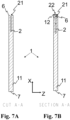
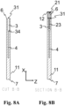
- the cuvette consists of a main body member, such as a single main body member, having inner walls defining the sampling cavity, the sample analysis cavity, and the venting cavity within the body.
- a single body member herein means that the cuvette is made of one integral part, for example by molding or casting.
- the sampling cavity, the sample analysis cavity and the venting cavity may be arranged in a main body member of the cuvette.
- the main body member of the cuvette may be made of a material having a low absorbance of radiation in wavelengths used during analysis of the blood sample.
- the material of the cuvette may be a plastic, such as polystyrene (PS), polymethylmethacrylate (PMMA), or polycarbonate (PC).
- the centrifugal force being applied to the cuvette may overcome the third capillary force holding the blood sample in the sampling cavity.
- the blood sample may thus leave the sampling cavity via the venting cavity and may enter the sample analysis cavity.
- the sample analysis cavity may be arranged offset from the sampling cavity in the longitudinal direction of the cuvette. Thereby, the centrifugal force may force the blood sample towards and into the sample analysis cavity.
- the cuvette may be configured to transfer, upon the centrifugal force being applied to the cuvette, air from the sample analysis cavity to an exterior of the cuvette via the venting cavity.
- air in the sample analysis cavity may escape the sample analysis cavity to an exterior of the cuvette via the second interface and the venting opening, thereby ensuring a proper filling of the sample analysis cavity.
- the sampling cavity and the sample analysis cavity have equal volumes, such as substantially equal volumes. Thereby, a predefined volume of the blood sample may be obtained by the sampling cavity and the same volume of the fluid can be analyzed in the sample analysis cavity.
- the volume of the sampling cavity may be in the range of 10-100 microliters ( ⁇ L), or 20-60 microliters ( ⁇ L), such as in the range of 30-50 ⁇ L, such as in the range of 30-40 ⁇ L, such as in the range of 30-35 ⁇ L, such as 32 ⁇ L.
- the volume of the sample analysis cavity may be in the range of 10-100 microliters ( ⁇ L), or 20-60 microliters ( ⁇ L), such as in the range of 30-50 ⁇ L, such as in the range of 30-40 ⁇ L, such as in the range of 30-35 ⁇ L, such as 32 ⁇ L.
- the sample analysis cavity has a substantially uniform elongated shape extending in a first direction between the first end and an opposing second end of the cuvette.
- the first end and the second end of the cuvette may be arranged at opposing longitudinal ends of the cuvette.
- the first direction may be parallel to an intended direction of the centrifugal force to be applied to the cuvette, such as to the direction of the centrifugal force applied to the cuvette when the cuvette is analyzed using the blood analyzer configured to receive the cuvette.
- an overall length of the cuvette such as an extension in the longitudinal direction of the cuvette as defined in Fig. 4 , may be in the range of 30-50 mm, or 36-44 mm, such as in the range of 38-42 mm, such as in the range of 39-40 mm.
- the overall length may be measured from the tip of the first longitudinal end of the cuvette to the second longitudinal end of the cuvette.
- an overall width of the cuvette such as an extension in a lateral direction of the cuvette as defined in Fig. 4 , may be in the range of 15-28 mm, or 18-24 mm, such as in the range of 19-23 mm, such as in the range of 20-22 mm. In one or more example methods, the width of the cuvette may be 21 mm.
- an overall width of the cuvette such as an extension in a vertical direction of the cuvette as defined in Fig. 4 , may be in the range of 1.9-2.4 mm, such as in the range of 2.0-2.3 mm, such as in the range of 2.1-2.2 mm.
- the sample analysis cavity may have a length, such as an extension in the longitudinal direction of the cuvette as defined in Fig. 4 , in the range of 10-20 mm, such as 10 mm, 11 mm, 12 mm, 13 mm, 14 mm, 15 mm, 16 mm, 17 mm, 18 mm, 19 mm or 20 mm, and/or any ranges constrained by the dimensions discussed in this paragraph.
- the sample analysis cavity may have a width, such as an extension in a lateral direction of the cuvette as defined in Fig. 4 , in the range of 2-7 mm, such as 2 mm, 3 mm, 4 mm, 5 mm, 6 mm or 7 mm, and/or any ranges constrained by the dimensions discussed in this paragraph.
- the sample analysis cavity may have a height, such as an extension in a vertical direction of the cuvette as defined in Fig. 4 , in the range of 0.2-0.7 mm, such as 0.2 mm, 0.3 mm, 0.4 mm, 0.5 mm, 0.6 mm or 0.7 mm, and/or any ranges constrained by the dimensions discussed in this paragraph.
- the height of the sample analysis cavity may be 0.5 mm, such as 500 ⁇ m.
- the sampling cavity may have a length, such as an average length, in the range of 5-15 mm, such as 5 mm, 6 mm, 7 mm, 8 mm, 9 mm, 10 mm, 11 mm, 12 mm, 13 mm, 14 mm or 15 mm, and/or any ranges constrained by the dimensions discussed in this paragraph.
- the sampling cavity may have a width, such as an average width, in the range of 5-15 mm, such as 5 mm, 6 mm, 7 mm, 8 mm, 9 mm, 10 mm, 11 mm, 12 mm, 13 mm, 14 mm or 15 mm, and/or any ranges constrained by the dimensions discussed in this paragraph.
- the sampling cavity may have a height, such as an extension in a vertical direction of the cuvette as defined in Fig. 4 , in the range of 0.2-0.7 mm, such as 0.2 mm, 0.3 mm, 0.4 mm, 0.5 mm, 0.6 mm or 0.7 mm, and/or any ranges constrained by the dimensions discussed in this paragraph.
- the height of the sampling cavity may be in the range of 500-650 ⁇ m, such as 575 ⁇ m.
- the venting cavity may have a length in the range of 5-10 mm, such as 5 mm, 6 mm, 7 mm, 8 mm, 9 mm or 10 mm, and/or any ranges constrained by the dimensions discussed in this paragraph.
- the body member comprises a tip.
- the sampling cavity may be arranged at the tip of the body member, such that the inlet of the sampling cavity is arranged at the tip of the cuvette.
- the sampling cavity such as an inner surface of the sampling cavity, is configured to slope towards the sample analysis cavity.
- the sampling cavity may be configured to slope outwards towards the opening of the further facilitates removal of a shaping tool after shaping of the cuvette.
- the cuvette such as the sample analysis cavity of the cuvette
- the analysis of the blood sample may be done by measuring directly at the hemoglobin (Hb) derivates comprised in the body.
- the hemoglobin derivatives may be for example reduced hemoglobin (Hb), such as deoxyhemoglobin (reduced), oxyhemoglobin (HbO2), methemoglobin (met-Hb), carboxyhemoglobin (HbCO) or other types of hemoglobin.
- Hb reduced hemoglobin
- Making the cuvette free of reagents reduced the cost of manufacturing the cuvette and also reduced the time it takes to manufacture the cuvette.
- the walls of the sampling cavity are coated with a wetting agent.
- the wetting agent may aid in taking up blood samples in the sampling cavity.
- the sample analysis cavity may comprise a reagent configured to react with the blood sample.
- the reagent may be arranged on an inner surface of the sample analysis cavity, such that it comes in contact with the blood sample when the blood sample enters the sample analysis cavity.
- the reagent may be applied to the sample analysis cavity during manufacturing of the cuvette. Different reagents may be provided in the cavity depending on the analysis that is to be performed, thereby enabling the cuvette to be adapted for analysis of different biological parameters of blood.
- the reagent may cause the different hemoglobin derivates to react into the same derivate, thereby reducing interference at the different wavelengths which may facilitate the analysis procedure of the blood sample.
- the cuvette may comprise a unique identifier for identifying each respective cuvette.
- the unique identifier may be a visual identifier, such as a barcode or a QR-code, or a digital identifier, such as a Radio Frequency Identification (RFID) tag.
- RFID Radio Frequency Identification
- the unique identifier may be used to identify the cuvette being used for a specific blood sample and/or analysis.
- the identifier may be identified by the blood analyzer and measurements from the blood analyzer may be automatically stored with the unique identifier of the cuvette.
- the cuvette may be a single-use cuvette, e.g. configured for one time use, such as may be disposable and is to be thrown away after having been used once for analysis.
- the cuvette may be manufactured by conventional means, e.g. as disclosed in WO 2007/008137 A1 .
- the method comprises arranging S102 a cuvette comprising a sampling cavity and a sample analysis cavity on a rotatable member.
- the sampling cavity comprises a blood sample to be analyzed.
- the method may comprise rotating S104 the rotatable member at an initial speed in an initial rotation cycle insufficient for transfer of the blood sample from the sampling cavity to the sample analysis cavity.
- the initial speed may create an initial centrifugal force acting on the blood sample during the initial rotation cycle that is below a capillary force acting on the blood sample in the sampling cavity.
- the initial speed may be insufficient for transferring blood from the sampling cavity to the sample analysis cavity.
- the sample analysis cavity will thus remain empty, wherein empty herein means not comprising any blood, which allows an initial measurement to be performed on the empty sample analysis cavity of the cuvette to detect any contamination or damages to the cuvette which could affect the analysis results of the blood sample.
- the initial rotation cycle is performed prior to a first rotation cycle.
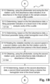
- providing S109 the output may comprise providing S109B the cuvette parameter to a compensation function which can compensate for the contamination level and/or the absorbance data of the empty cuvette, during subsequent measurements and determination of blood parameters using the cuvette.
- the method may comprise obtaining S112, using the photometer and during the first rotation cycle, a first absorbance data indicative of an absorbance in the blood sample in the sample analysis cavity of the cuvette.
- the method may comprise determining S113, based on the first absorbance data, a filling parameter indicative of a blood level, such as indicative of a fill level, such as indicative of the amount of blood, in the sample analysis cavity of the cuvette.
- the filling parameter may, in one or more example methods, be indicative of one or more of the sample analysis cavity being underfilled, the sample analysis cavity being incorrectly filled, and the sample analysis cavity being correctly filled.
- the sample analysis cavity may be determined to be underfilled when the first absorbance data is below a first blood level threshold. A too low blood level, such as an underfilled cuvette, may cause the absorbance data to be lower than when the sample analysis cavity is correctly filled.
- the sample analysis cavity being incorrectly filled can herein be seen as not being filled with blood, such as being filled with a fluid other than blood.
- the method may comprise determining S114, based on the first absorbance data, a first blood parameter being, such as being indicative of, a total hemoglobin level of the blood sample.
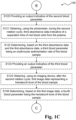
- the method comprises rotating S116 the rotatable member at a second speed in a second rotation cycle for separating blood parts from plasma in the blood sample.
- the second rotation cycle may be performed after the first rotation cycle.
- the method comprises obtaining S118, using a photometer, during or after the second rotation cycle, second absorbance data.
- the second absorbance data being indicative of absorbance in the plasma.
- the method comprises determining S119, based on the second absorbance data, a second blood parameter.
- the second blood parameter being, such as being indicative of, a plasma free hemoglobin level of the blood sample.
- the method comprises providing S120 an output indicative of the second blood parameter.
- the method may comprise obtaining S121, using the photometer, during the second rotation cycle, third absorbance data indicative of a separation time of red blood cells from the plasma.
- the method may comprise obtaining S124, using an imaging device, after the second rotation cycle, first image data representing an image of at least a part of the blood sample in the sample analysis cavity.
- the method may comprise obtaining S132, using the photometer and during the third rotation cycle, fourth absorbance data indicative of an absorbance in the blood sample in the sample analysis cavity of the cuvette.
- the method may comprise determining S134, based on the fourth absorbance data, a fifth blood parameter.
- the fifth blood parameter may be a second plasma free hemoglobin level indicating fragile blood cells of the blood sample. By comparing the second plasma free hemoglobin level with the first plasma free hemoglobin level a level of fragile blood cells in the blood sample can be determined.
- the method may comprise providing S136 an output indicative of the fifth blood parameter, such as displaying information indicative of the fifth blood parameter.
- Fig. 2 illustrates a schematic of an example blood analyzer 100 according to this disclosure.
- the blood analyzer 100 can comprise a housing 110, which can accommodate any and/or all of the parts of the blood analyzer 100 discussed herein, such as the rotatable member, the photometer, the controller, the display and/or the drive unit.
- the blood analyzer 100 comprises a rotatable member 200.
- the rotatable member 200 is rotatably arranged in the housing 110.
- the rotatable member 200 may be rotatable arranged around a rotational axis 202.
- the rotatable member comprises a receptacle 204 for receiving a cuvette.
- the cuvette comprises a sampling cavity and a sample analysis cavity.
- the sampling cavity of the cuvette is intended to comprise a blood sample to be analyzed, whereas the sample analysis cavity is intended to be empty. Empty herein means that the sample analysis cavity does not comprise any blood sample but may comprise air.
- the rotatable member 200 may be a circular member, such as a disc.
- the receptacle 204 can comprise a measuring eye 206, such as an opening, for allowing light to pass through the rotatable member 200.
- the measuring eye 206 may be arranged in the receptacle 204 so that the measuring eye 206, in at least a first angular position of the rotatable member 200, overlaps with the sample analysis cavity of the cuvette, when the cuvette is arranged in the receptacle 204.
- the measuring eye 206 can be arranged at a distance r from the rotational axis 202 on the rotatable member 200.
- the blood analyzer 100 can comprise a drive unit 208, such as an electric motor, for driving, such as rotating, the rotatable member 200.
- the blood analyzer 100 comprises a photometer 300.
- the photometer 300 is configured to obtain, such as measure, absorbance data associated with the sample analysis cavity and/or the blood sample of the cuvette.
- the photometer 300 can be a multi-wavelength photometer.
- the photometer 300 can comprise a light source 302 for emitting light at respective wavelengths and an optical sensor 304, such as a photo diode, for measuring how much light is absorbed by an object located between the light source 302 and the optical sensor 304.
- the blood analyzer 100 can comprise a display 500 configured to visually provide information to an operator of the blood analyzer 100, such as for visually displaying information indicative of the cuvette parameter, the first blood parameter, the second blood parameter, the third blood parameter, the fourth blood parameter, and/or the fifth blood parameter.
- the blood analyzer 100 can comprise a display 500 for displaying, such as visually providing, information to an operator of the blood analyzer 100.
- the blood analyzer 400 can comprise an imaging device 306, such as a camera, for taking images associated with the sample analysis cavity and/or the blood sample of the cuvette.
- an imaging device 306 such as a camera
- the blood analyzer can comprise a controller 400.
- the controller 400 can be configured to control the photometer 300, any imaging device 306, the rotatable member 200, the drive unit 208 and/or the display 500.
- the controller 400 may be configured to perform any one of the of the operations disclosed in Fig. 1a-1d (such as any one or more of S102, S104, S106, S108, S110, S112, S114, S116, S118, S119, S120, S121, S122, S123, S124, S126, S128, S130, S132, S134).
- the controller 400 may be configured to control the drive unit 208 to control the speed of the rotatable member 200.
- the controller 400 can be configured to rotate the rotatable member 200 at a first speed in a first rotation cycle for transferring the blood sample from the sampling cavity to the sample analysis cavity.
- the controller 400 can be configured to rotate the rotatable member 200 at a second speed in a second rotation cycle after the first rotation cycle for separating blood parts from plasma in the blood sample.
- the controller 400 can be configured to control the photometer 300 to obtain, during the second rotation cycle, second absorbance data indicative of absorbance in the plasma of the separated blood sample.
- the controller 400 can be configured to determine, based on the second absorbance data, a second blood parameter being, such as being indicative of, a plasma free hemoglobin level of the blood sample.
- the controller 400 can be configured to provide an output, such as to the display 500, indicative of the second blood parameter.
- the controller 400 can be configured to, prior to the first rotation cycle, rotate the rotatable member 200 at an initial speed in an initial rotation cycle.
- the initial speed is insufficient for transfer of the blood sample from the sampling cavity to the sample analysis cavity.
- the controller 400 can be configured to control the photometer 300 to obtain, during the initial rotation cycle, initial absorbance data indicative of an absorbance in the sample analysis cavity of the cuvette.
- the controller 400 can be configured to determine, based on the initial absorbance data, a cuvette parameter being, such as being indicative of, a contamination level associated with the cuvette.
- the plurality of light sources 302A, 302B, 302C may be arranged on a first side of the rotatable member 200 and the one or more optical sensors 304A, 304B, 304C may be arranged on a second side of the rotatable member 200.
- the first side of the rotatable member 200 and the second side of the rotatable member 200 may be opposite sides of the rotatable member 200.
- the light sources 302A, 302B, 302C can be LEDs.
- Each light source 302A, 302B, 302C can be configured to emit light at a different wavelength.
- the photometer 300 can be configured to obtain the initial absorbance data, the first absorbance data, the second absorbance data, the third absorbance data, and/or the fourth absorbance data by measuring absorbance using more than two wavelengths.
Landscapes
- Health & Medical Sciences (AREA)
- Chemical & Material Sciences (AREA)
- Life Sciences & Earth Sciences (AREA)
- Physics & Mathematics (AREA)
- Engineering & Computer Science (AREA)
- General Health & Medical Sciences (AREA)
- Analytical Chemistry (AREA)
- General Physics & Mathematics (AREA)
- Immunology (AREA)
- Pathology (AREA)
- Biochemistry (AREA)
- Hematology (AREA)
- Biomedical Technology (AREA)
- Spectroscopy & Molecular Physics (AREA)
- Dispersion Chemistry (AREA)
- Molecular Biology (AREA)
- Urology & Nephrology (AREA)
- Food Science & Technology (AREA)
- Medicinal Chemistry (AREA)
- Chemical Kinetics & Catalysis (AREA)
- Clinical Laboratory Science (AREA)
- Ecology (AREA)
- Biophysics (AREA)
- Computer Vision & Pattern Recognition (AREA)
- Medical Informatics (AREA)
- Nuclear Medicine, Radiotherapy & Molecular Imaging (AREA)
- Quality & Reliability (AREA)
- Radiology & Medical Imaging (AREA)
- Theoretical Computer Science (AREA)
- Biotechnology (AREA)
- Cell Biology (AREA)
- Microbiology (AREA)
- Investigating Or Analysing Biological Materials (AREA)
- Investigating Or Analysing Materials By Optical Means (AREA)
- Automatic Analysis And Handling Materials Therefor (AREA)
Claims (15)
- Verfahren zur Analyse einer Blutprobe, wobei das Verfahren Folgendes umfasst:- Anordnen (S102) einer Küvette, die einen Probenahmehohlraum und einen Probenanalysehohlraum umfasst, auf einem rotierbaren Element, wobei der Probenahmehohlraum eine zu analysierende Blutprobe umfasst;- vor dem ersten Rotationszyklus, Rotieren (S104) des rotierbaren Elements mit einer Anfangsgeschwindigkeit in einem Anfangsrotationszyklus, wobei die Anfangsgeschwindigkeit nicht ausreicht, um die Blutprobe aus dem Probenahmehohlraum in den Probenanalysehohlraum zu überführen,- Erhalten (S106) von anfänglichen Absorptionsdaten, die eine Absorption in oder durch den Probenanalysehohlraum der Küvette anzeigen, unter Verwendung eines Photometers während des anfänglichen Rotationszyklus,- Bestimmen (S108), basierend auf den anfänglichen Absorptionsdaten, eines Küvettenparameters, der mit der Küvette verbunden ist,- Bereitstellen (S109) einer Ausgabe, die den Küvettenparameter anzeigt,- Rotieren (S110) des rotierbaren Elements mit einer ersten Geschwindigkeit in einem ersten Rotationszyklus zur Überführung der Blutprobe aus dem Probenahmehohlraum in den Probenanalysehohlraum;- Rotieren (S116) des rotierbaren Elements mit einer zweiten Geschwindigkeit in einem zweiten Rotationszyklus nach dem ersten Rotationszyklus zum Trennen von Blutteilen von dem Plasma in der Blutprobe;- Erhalten (S118) von zweiten Absorptionsdaten, die die Absorption in dem Plasma anzeigen, unter Verwendung des Photometers während des zweiten Rotationszyklus;- Bestimmen (S119), basierend auf den zweiten Absorptionsdaten, eines zweiten Blutparameters, der ein plasmafreier Hämoglobinspiegel der Blutprobe ist; und Bereitstellen (S120) einer Ausgabe, die den zweiten Blutparameter anzeigt.
- Verfahren nach einem der vorstehenden Ansprüche, wobei das Erhalten (S118) das kontinuierliche Erhalten (S118A) der zweiten Absorptionsdaten während des zweiten Rotationszyklus umfasst, und wobei das Verfahren Folgendes umfasst:beim Erkennen einer Stabilisierung der zweiten Absorptionsdaten, Beenden des kontinuierlichen Erhaltens (S118A) der zweiten Absorptionsdaten.
- Verfahren nach einem der vorstehenden Ansprüche, wobei das Verfahren Folgendes umfasst:- Erhalten (S112), unter Verwendung des Photometers und während des ersten Rotationszyklus, von ersten Absorptionsdaten, die eine Absorption in der Blutprobe in dem Probenanalysehohlraum der Küvette anzeigen,- Bestimmen (S114), basierend auf den ersten Absorptionsdaten, eines ersten Blutparameters, der ein Gesamthämoglobinwert der Blutprobe ist.
- Verfahren nach Anspruch 3, wobei das Verfahren Folgendes umfasst:- Erhalten (S121), unter Verwendung des Photometers, während des zweiten Rotationszyklus, von dritten Absorptionsdaten, die eine Trennungszeit von roten Blutkörperchen von dem Plasma anzeigen;- Bestimmen (S122), basierend auf den dritten Absorptionsdaten und den ersten Absorptionsdaten, eines dritten Blutparameters, der eine Erythrozytensedimentationsrate der Blutprobe ist; und Bereitstellen (S123) einer Ausgabe, die den dritten Blutparameter anzeigt.
- Verfahren nach einem der vorstehenden Ansprüche, wobei das Verfahren Folgendes umfasst:- Erhalten (S124) von ersten Bilddaten, die ein Bild von mindestens einem Teil der Blutprobe in dem Probenanalysehohlraum darstellen, unter Verwendung einer Abbildungsvorrichtung nach dem zweiten Rotationszyklus;- Bestimmen (S126), basierend auf den ersten Bilddaten, eines vierten Blutparameters, der ein Hämatokritwert der Blutprobe ist; und Bereitstellen (S128) einer Ausgabe, die den vierten Blutparameter anzeigt.
- Verfahren nach einem der vorstehenden Ansprüche, wobei das Verfahren Folgendes umfasst:- nach dem zweiten Rotationszyklus, Rotieren (S130) des rotierbaren Elements mit einer dritten Geschwindigkeit in einem dritten Rotationszyklus, wobei die dritte Geschwindigkeit höher ist als die erste Geschwindigkeit, die zweite Geschwindigkeit und die Anfangsgeschwindigkeit,- Erhalten (S132), unter Verwendung des Photometers und während des dritten Rotationszyklus, von vierten Absorptionsdaten, die eine Absorption in der Blutprobe in dem Probenanalysehohlraum der Küvette anzeigen, und- Bestimmen (S134) eines fünften Blutparameters auf der Grundlage der vierten Absorptionsdaten, wobei es sich um einen zweiten plasmafreien Hämoglobinspiegel handelt, der fragile Blutzellen der Blutprobe anzeigt.
- Verfahren nach einem der vorstehenden Ansprüche, wobei das Erhalten von anfänglichen Absorptionsdaten, ersten Absorptionsdaten, zweiten Absorptionsdaten, dritten Absorptionsdaten oder vierten Absorptionsdaten das Messen der Absorption unter Verwendung von mehr als zwei Wellenlängen umfasst.
- Verfahren nach einem der vorstehenden Ansprüche, wobei das Erhalten von anfänglichen Absorptionsdaten, ersten Absorptionsdaten, zweiten Absorptionsdaten, dritten Absorptionsdaten oder vierten Absorptionsdaten das Messen von Absorptionsdaten während einer Vielzahl von Umdrehungen des rotierbaren Elements umfasst.
- Verfahren nach einem der vorstehenden Ansprüche, wobei das Bestimmen eines oder mehrerer des ersten Blutparameters, des zweiten Blutparameters, des dritten Blutparameters, des vierten Blutparameters, des fünften Parameters und des Küvettenparameters das Integrieren von Absorptionsdaten umfasst, die während einer Vielzahl von Umdrehungen des rotierbaren Elements erhalten wurden.
- Blutanalysegerät (100), das ein Gehäuse (110), ein rotierbares Element (200), ein Photometer (300) und eine Steuerung(400) umfasst,- wobei das rotierbare Element (200) rotierbar in dem Gehäuse (110) angeordnet ist und eine Aufnahme (204) zur Aufnahme einer Küvette (1) umfasst, die einen Probenahmehohlraum (2) und einen Probenanalysehohlraum (4) umfasst, wobei der Probenahmehohlraum (2) der Küvette (1) eine zu analysierende Blutprobe umfasst;- wobei das Photometer (300) so konfiguriert ist, dass es Absorptionsdaten erhält, die mit dem Probenanalysehohlraum (4) der Küvette (1) verbunden sind;wobei die Steuerung (400) konfiguriert ist um Folgendes zu tun:- Rotieren des rotierbaren Elements (200) mit einer Anfangsgeschwindigkeit in einem Anfangsrotationszyklus vor einem ersten Rotationszyklus, wobei die Anfangsgeschwindigkeit nicht ausreicht, um die Blutprobe aus dem Probenahmehohlraum (2) in den Probenanalysehohlraum (4) zu überführen,- Steuern des Photometers (300), um während des Anfangsrotationszyklus anfängliche Absorptionsdaten zu erhalten, die eine Absorption in dem Probenanalysehohlraum (4) der Küvette (1) anzeigen;- Bestimmen, auf der Grundlage der anfänglichen Absorptionsdaten, eines mit der Küvette (1) verbundenen Küvettenparameters, und- Bereitstellen einer Ausgabe, die den Küvettenparameter anzeigt,- Rotieren des rotierbaren Elements (200) mit einer ersten Geschwindigkeit in einem ersten Rotationszyklus zum Überführen der Blutprobe aus dem Probenahmehohlraum (2) in den Probenanalysehohlraum (4);- Rotieren des rotierbaren Elements (200) mit einer zweiten Geschwindigkeit in einem zweiten Rotationszyklus nach dem ersten Rotationszyklus zum Trennen von Blutteilen von dem Plasma in der Blutprobe;- Steuern des Photometers (300), um während des zweiten Rotationszyklus zweite Absorptionsdaten zu erhalten, die die Absorption in dem Plasma der abgetrennten Blutprobe anzeigen; und- Bestimmen, auf der Grundlage der zweiten Absorptionsdaten, eines zweiten Blutparameters, bei dem es sich um einen plasmafreien Hämoglobinspiegel der Blutprobe handelt; und- Bereitstellen einer Ausgabe, die den zweiten Blutparameter anzeigt.
- Blutanalysegerät (100) nach Anspruch 10, wobei die Steuerung (400) so konfiguriert ist, dass sie das Photometer (300) so steuert, dass es während des zweiten Rotationszyklus kontinuierlich die zweiten Absorptionsdaten erhält, und dass sie, wenn sie eine Stabilisierung der zweiten Absorptionsdaten feststellt, das Photometer (300) so steuert, dass es das kontinuierliche Erhalten der zweiten Absorptionsdaten beendet.
- Blutanalysegerät (100) nach einem der Ansprüche 10 bis 11, wobei das Photometer (300) so konfiguriert ist, dass es anfängliche Absorptionsdaten, erste Absorptionsdaten, zweite Absorptionsdaten, dritte Absorptionsdaten oder fünfte Absorptionsdaten durch Messung der Absorption unter Verwendung von mehr als zwei Wellenlängen erhält.
- Blutanalysegerät (100) nach Anspruch 12, wobei das Photometer (300) mindestens zwei Lichtquellen (302) und mindestens zwei entsprechende optische Sensoren (304) umfasst, wobei jede Lichtquelle Licht mit einer anderen Wellenlänge aussendet.
- Blutanalysegerät (100) nach einem der Ansprüche 10 bis 13, wobei die Steuerung (400) so konfiguriert ist, dass sie das Photometer (300) bzw. jede Abbildungsvorrichtung (306) steuert, um anfängliche Absorptionsdaten, erste Absorptionsdaten, zweite Absorptionsdaten, dritte Absorptionsdaten, erste Bilddaten oder vierte Absorptionsdaten während einer Vielzahl von Umdrehungen des rotierbaren Elements (200) zu messen.
- Blutanalysegerät (100) nach Anspruch 14, wobei die Steuerung (400) so konfiguriert ist, dass sie Absorptionsdaten integriert, die von dem Photometer während der Vielzahl von Umdrehungen des rotierbaren Elements (200) erhalten werden.
Priority Applications (1)
| Application Number | Priority Date | Filing Date | Title |
|---|---|---|---|
| EP25166729.1A EP4553499A3 (de) | 2021-12-23 | 2022-12-20 | Verfahren und analysator zur analyse einer blutprobe |
Applications Claiming Priority (2)
| Application Number | Priority Date | Filing Date | Title |
|---|---|---|---|
| EP21217560 | 2021-12-23 | ||
| PCT/EP2022/086903 WO2023118079A1 (en) | 2021-12-23 | 2022-12-20 | Method and analyzer for analyzing a blood sample |
Related Child Applications (1)
| Application Number | Title | Priority Date | Filing Date |
|---|---|---|---|
| EP25166729.1A Division EP4553499A3 (de) | 2021-12-23 | 2022-12-20 | Verfahren und analysator zur analyse einer blutprobe |
Publications (2)
| Publication Number | Publication Date |
|---|---|
| EP4334717A1 EP4334717A1 (de) | 2024-03-13 |
| EP4334717B1 true EP4334717B1 (de) | 2025-04-02 |
Family
ID=79230870
Family Applications (2)
| Application Number | Title | Priority Date | Filing Date |
|---|---|---|---|
| EP22840684.9A Active EP4334717B1 (de) | 2021-12-23 | 2022-12-20 | Verfahren und analysator zur analyse einer blutprobe |
| EP25166729.1A Pending EP4553499A3 (de) | 2021-12-23 | 2022-12-20 | Verfahren und analysator zur analyse einer blutprobe |
Family Applications After (1)
| Application Number | Title | Priority Date | Filing Date |
|---|---|---|---|
| EP25166729.1A Pending EP4553499A3 (de) | 2021-12-23 | 2022-12-20 | Verfahren und analysator zur analyse einer blutprobe |
Country Status (7)
| Country | Link |
|---|---|
| US (1) | US20240280472A1 (de) |
| EP (2) | EP4334717B1 (de) |
| JP (1) | JP2025501607A (de) |
| KR (1) | KR20240163201A (de) |
| CN (1) | CN118661100A (de) |
| ES (1) | ES3030518T3 (de) |
| WO (1) | WO2023118079A1 (de) |
Family Cites Families (9)
| Publication number | Priority date | Publication date | Assignee | Title |
|---|---|---|---|---|
| US6153148A (en) * | 1998-06-15 | 2000-11-28 | Becton, Dickinson And Company | Centrifugal hematology disposable |
| ES2348085T3 (es) * | 2003-07-02 | 2010-11-30 | Caridianbct, Inc. | Sistema de control y monitorizacion para el procesamiento de sangre. |
| SE529643C3 (sv) | 2005-07-08 | 2007-11-06 | Hemocue Ab | En kuvett och en metod och ett verktyg för tillverkning därav |
| EP2096444B1 (de) * | 2006-10-31 | 2016-12-07 | Panasonic Healthcare Holdings Co., Ltd. | Mikrochip und analysegerät damit |
| JP6342181B2 (ja) * | 2014-02-24 | 2018-06-13 | キヤノンメディカルシステムズ株式会社 | 自動分析装置 |
| GB2525622A (en) * | 2014-04-29 | 2015-11-04 | Imp Innovations Ltd | Optical analysis of fluid volumes under centrifugation |
| EP3312586B1 (de) * | 2015-06-16 | 2020-12-16 | Tascom Co., Ltd. | Messinstrument für biologisches material |
| JP6626196B2 (ja) * | 2015-11-18 | 2019-12-25 | ラジオメーター・メディカル・アー・ペー・エス | 流体中の検体を光学的に検出するための多孔質ミラー |
| US10288600B2 (en) * | 2016-05-20 | 2019-05-14 | Instrumentation Laboratory Company | Evanescent hemolysis detection |
-
2022
- 2022-12-20 KR KR1020247023851A patent/KR20240163201A/ko active Pending
- 2022-12-20 US US18/567,941 patent/US20240280472A1/en active Pending
- 2022-12-20 EP EP22840684.9A patent/EP4334717B1/de active Active
- 2022-12-20 WO PCT/EP2022/086903 patent/WO2023118079A1/en not_active Ceased
- 2022-12-20 ES ES22840684T patent/ES3030518T3/es active Active
- 2022-12-20 JP JP2024538227A patent/JP2025501607A/ja active Pending
- 2022-12-20 EP EP25166729.1A patent/EP4553499A3/de active Pending
- 2022-12-20 CN CN202280091145.XA patent/CN118661100A/zh active Pending
Also Published As
| Publication number | Publication date |
|---|---|
| CN118661100A (zh) | 2024-09-17 |
| ES3030518T3 (en) | 2025-06-30 |
| KR20240163201A (ko) | 2024-11-18 |
| JP2025501607A (ja) | 2025-01-22 |
| EP4553499A3 (de) | 2025-07-16 |
| WO2023118079A1 (en) | 2023-06-29 |
| EP4553499A2 (de) | 2025-05-14 |
| US20240280472A1 (en) | 2024-08-22 |
| EP4334717A1 (de) | 2024-03-13 |
Similar Documents
| Publication | Publication Date | Title |
|---|---|---|
| US5308506A (en) | Apparatus and method for separating a sample of blood | |
| US5030341A (en) | Apparatus for separating phases of blood | |
| JP6725656B2 (ja) | 全血サンプル中の遊離ヘモグロビンを検出するための光学センサ | |
| JP2776883B2 (ja) | 分離装置 | |
| US6506606B1 (en) | Method and apparatus for determining erythrocyte sedimentation rate and hematocrit | |
| WO2015179969A1 (en) | Joint spectroscopic and biosensor system for point-of-care testing | |
| KR102546374B1 (ko) | 적혈구 침강 속도 및 다른 연결된 파라미터를 결정하기 위한 장치 및 방법 | |
| EP3553498B1 (de) | Optische erfassung und messung von hämatokrit und freier hämoglobinkonzentration | |
| CA2507323A1 (en) | Diagnostic whole blood and plasma apparatus | |
| CN112119294A (zh) | 多孔膜传感器元件 | |
| US20240328925A1 (en) | Cuvette for body fluid analysis | |
| JP7752204B2 (ja) | センサ組立体および多孔質膜センサ素子 | |
| EP4334717B1 (de) | Verfahren und analysator zur analyse einer blutprobe | |
| KR20090123039A (ko) | 혈액 분리 장치 | |
| Stephen et al. | Analytical comparison between microhematocrit and automated methods for packed cell volume (PCV) determination | |
| KR20110096036A (ko) | 혈구 침강 제어 기구를 구비한 혈액 분석기 및 사용 방법 | |
| EP3982323A1 (de) | System und verfahren zur quantifizierung einer phase in einer dispersion | |
| CA1338468C (en) | Apparatus for separating phases of blood | |
| Pannu et al. | Warfarin related nephropathy: a case report from a tertiary hospital of north India and review of literature | |
| EP4558802A1 (de) | Blutanalysesystem am versorgungsort |
Legal Events
| Date | Code | Title | Description |
|---|---|---|---|
| STAA | Information on the status of an ep patent application or granted ep patent |
Free format text: STATUS: UNKNOWN |
|
| STAA | Information on the status of an ep patent application or granted ep patent |
Free format text: STATUS: THE INTERNATIONAL PUBLICATION HAS BEEN MADE |
|
| PUAI | Public reference made under article 153(3) epc to a published international application that has entered the european phase |
Free format text: ORIGINAL CODE: 0009012 |
|
| STAA | Information on the status of an ep patent application or granted ep patent |
Free format text: STATUS: REQUEST FOR EXAMINATION WAS MADE |
|
| 17P | Request for examination filed |
Effective date: 20231204 |
|
| AK | Designated contracting states |
Kind code of ref document: A1 Designated state(s): AL AT BE BG CH CY CZ DE DK EE ES FI FR GB GR HR HU IE IS IT LI LT LU LV MC ME MK MT NL NO PL PT RO RS SE SI SK SM TR |
|
| GRAP | Despatch of communication of intention to grant a patent |
Free format text: ORIGINAL CODE: EPIDOSNIGR1 |
|
| STAA | Information on the status of an ep patent application or granted ep patent |
Free format text: STATUS: GRANT OF PATENT IS INTENDED |
|
| DAV | Request for validation of the european patent (deleted) | ||
| DAX | Request for extension of the european patent (deleted) | ||
| INTG | Intention to grant announced |
Effective date: 20241112 |
|
| GRAS | Grant fee paid |
Free format text: ORIGINAL CODE: EPIDOSNIGR3 |
|
| GRAA | (expected) grant |
Free format text: ORIGINAL CODE: 0009210 |
|
| STAA | Information on the status of an ep patent application or granted ep patent |
Free format text: STATUS: THE PATENT HAS BEEN GRANTED |
|
| P01 | Opt-out of the competence of the unified patent court (upc) registered |
Free format text: CASE NUMBER: APP_5634/2025 Effective date: 20250203 |
|
| AK | Designated contracting states |
Kind code of ref document: B1 Designated state(s): AL AT BE BG CH CY CZ DE DK EE ES FI FR GB GR HR HU IE IS IT LI LT LU LV MC ME MK MT NL NO PL PT RO RS SE SI SK SM TR |
|
| REG | Reference to a national code |
Ref country code: GB Ref legal event code: FG4D |
|
| REG | Reference to a national code |
Ref country code: CH Ref legal event code: EP |
|
| REG | Reference to a national code |
Ref country code: IE Ref legal event code: FG4D |
|
| REG | Reference to a national code |
Ref country code: DE Ref legal event code: R096 Ref document number: 602022012706 Country of ref document: DE |
|
| REG | Reference to a national code |
Ref country code: NL Ref legal event code: FP |
|
| REG | Reference to a national code |
Ref country code: SE Ref legal event code: TRGR |
|
| REG | Reference to a national code |
Ref country code: ES Ref legal event code: FG2A Ref document number: 3030518 Country of ref document: ES Kind code of ref document: T3 Effective date: 20250630 |
|
| REG | Reference to a national code |
Ref country code: AT Ref legal event code: MK05 Ref document number: 1781735 Country of ref document: AT Kind code of ref document: T Effective date: 20250402 |
|
| PG25 | Lapsed in a contracting state [announced via postgrant information from national office to epo] |
Ref country code: FI Free format text: LAPSE BECAUSE OF FAILURE TO SUBMIT A TRANSLATION OF THE DESCRIPTION OR TO PAY THE FEE WITHIN THE PRESCRIBED TIME-LIMIT Effective date: 20250402 Ref country code: PT Free format text: LAPSE BECAUSE OF FAILURE TO SUBMIT A TRANSLATION OF THE DESCRIPTION OR TO PAY THE FEE WITHIN THE PRESCRIBED TIME-LIMIT Effective date: 20250804 |
|
| REG | Reference to a national code |
Ref country code: LT Ref legal event code: MG9D |
|
| PG25 | Lapsed in a contracting state [announced via postgrant information from national office to epo] |
Ref country code: GR Free format text: LAPSE BECAUSE OF FAILURE TO SUBMIT A TRANSLATION OF THE DESCRIPTION OR TO PAY THE FEE WITHIN THE PRESCRIBED TIME-LIMIT Effective date: 20250703 Ref country code: NO Free format text: LAPSE BECAUSE OF FAILURE TO SUBMIT A TRANSLATION OF THE DESCRIPTION OR TO PAY THE FEE WITHIN THE PRESCRIBED TIME-LIMIT Effective date: 20250702 |
|
| PG25 | Lapsed in a contracting state [announced via postgrant information from national office to epo] |
Ref country code: PL Free format text: LAPSE BECAUSE OF FAILURE TO SUBMIT A TRANSLATION OF THE DESCRIPTION OR TO PAY THE FEE WITHIN THE PRESCRIBED TIME-LIMIT Effective date: 20250402 |
|
| PG25 | Lapsed in a contracting state [announced via postgrant information from national office to epo] |
Ref country code: BG Free format text: LAPSE BECAUSE OF FAILURE TO SUBMIT A TRANSLATION OF THE DESCRIPTION OR TO PAY THE FEE WITHIN THE PRESCRIBED TIME-LIMIT Effective date: 20250402 |
|
| PG25 | Lapsed in a contracting state [announced via postgrant information from national office to epo] |
Ref country code: HR Free format text: LAPSE BECAUSE OF FAILURE TO SUBMIT A TRANSLATION OF THE DESCRIPTION OR TO PAY THE FEE WITHIN THE PRESCRIBED TIME-LIMIT Effective date: 20250402 |
|
| PG25 | Lapsed in a contracting state [announced via postgrant information from national office to epo] |
Ref country code: AT Free format text: LAPSE BECAUSE OF FAILURE TO SUBMIT A TRANSLATION OF THE DESCRIPTION OR TO PAY THE FEE WITHIN THE PRESCRIBED TIME-LIMIT Effective date: 20250402 |
|
| PG25 | Lapsed in a contracting state [announced via postgrant information from national office to epo] |
Ref country code: RS Free format text: LAPSE BECAUSE OF FAILURE TO SUBMIT A TRANSLATION OF THE DESCRIPTION OR TO PAY THE FEE WITHIN THE PRESCRIBED TIME-LIMIT Effective date: 20250702 |
|
| PG25 | Lapsed in a contracting state [announced via postgrant information from national office to epo] |
Ref country code: IS Free format text: LAPSE BECAUSE OF FAILURE TO SUBMIT A TRANSLATION OF THE DESCRIPTION OR TO PAY THE FEE WITHIN THE PRESCRIBED TIME-LIMIT Effective date: 20250802 |
|
| PG25 | Lapsed in a contracting state [announced via postgrant information from national office to epo] |
Ref country code: LV Free format text: LAPSE BECAUSE OF FAILURE TO SUBMIT A TRANSLATION OF THE DESCRIPTION OR TO PAY THE FEE WITHIN THE PRESCRIBED TIME-LIMIT Effective date: 20250402 |