EP4334692B1 - System zur messung des thermischen komforts - Google Patents
System zur messung des thermischen komforts Download PDFInfo
- Publication number
- EP4334692B1 EP4334692B1 EP22720523.4A EP22720523A EP4334692B1 EP 4334692 B1 EP4334692 B1 EP 4334692B1 EP 22720523 A EP22720523 A EP 22720523A EP 4334692 B1 EP4334692 B1 EP 4334692B1
- Authority
- EP
- European Patent Office
- Prior art keywords
- sensor
- air
- temperature
- heat flux
- determining
- Prior art date
- Legal status (The legal status is an assumption and is not a legal conclusion. Google has not performed a legal analysis and makes no representation as to the accuracy of the status listed.)
- Active
Links
Images
Classifications
-
- G—PHYSICS
- G01—MEASURING; TESTING
- G01K—MEASURING TEMPERATURE; MEASURING QUANTITY OF HEAT; THERMALLY-SENSITIVE ELEMENTS NOT OTHERWISE PROVIDED FOR
- G01K17/00—Measuring quantity of heat
- G01K17/06—Measuring quantity of heat conveyed by flowing media, e.g. in heating systems e.g. the quantity of heat in a transporting medium, delivered to or consumed in an expenditure device
- G01K17/08—Measuring quantity of heat conveyed by flowing media, e.g. in heating systems e.g. the quantity of heat in a transporting medium, delivered to or consumed in an expenditure device based upon measurement of temperature difference or of a temperature
- G01K17/20—Measuring quantity of heat conveyed by flowing media, e.g. in heating systems e.g. the quantity of heat in a transporting medium, delivered to or consumed in an expenditure device based upon measurement of temperature difference or of a temperature across a radiating surface, combined with ascertainment of the heat-transmission coefficient
-
- G—PHYSICS
- G01—MEASURING; TESTING
- G01K—MEASURING TEMPERATURE; MEASURING QUANTITY OF HEAT; THERMALLY-SENSITIVE ELEMENTS NOT OTHERWISE PROVIDED FOR
- G01K17/00—Measuring quantity of heat
-
- A—HUMAN NECESSITIES
- A61—MEDICAL OR VETERINARY SCIENCE; HYGIENE
- A61B—DIAGNOSIS; SURGERY; IDENTIFICATION
- A61B5/00—Measuring for diagnostic purposes; Identification of persons
- A61B5/0002—Remote monitoring of patients using telemetry, e.g. transmission of vital signals via a communication network
- A61B5/0004—Remote monitoring of patients using telemetry, e.g. transmission of vital signals via a communication network characterised by the type of physiological signal transmitted
- A61B5/0008—Temperature signals
-
- G—PHYSICS
- G01—MEASURING; TESTING
- G01K—MEASURING TEMPERATURE; MEASURING QUANTITY OF HEAT; THERMALLY-SENSITIVE ELEMENTS NOT OTHERWISE PROVIDED FOR
- G01K7/00—Measuring temperature based on the use of electric or magnetic elements directly sensitive to heat ; Power supply therefor, e.g. using thermoelectric elements
- G01K7/16—Measuring temperature based on the use of electric or magnetic elements directly sensitive to heat ; Power supply therefor, e.g. using thermoelectric elements using resistive elements
-
- G—PHYSICS
- G01—MEASURING; TESTING
- G01W—METEOROLOGY
- G01W1/00—Meteorology
- G01W1/17—Catathermometers for measuring "cooling value" related either to weather conditions or to comfort of other human environment
Definitions
- Thermal comfort is defined by ISO 7730 clause 7 as that condition of mind which expresses satisfaction with the thermal environment and is assessed using subjective evaluation.
- the 7730 standard presents methods to predict thermal sensation and degree of discomfort of people exposed to moderate thermal environments, like in homes, offices and cars. The methods are centered around the determination of the Predicted Mean Vote (PMV) and the associated Predicted Percentage of Dissatisfied (PPD). Knowing the PMV, the PPD can directly be calculated.
- PMV Predicted Mean Vote
- PPD Predicted Percentage of Dissatisfied
- the mean radiant temperature is defined as the uniform temperature of an imaginary enclosure in which radiant heat transfer from the human body is equal to the radiant heat transfer in the actual non-uniform enclosure.
- the mean radiant temperature may also be calculated from measured values if the plane radiant temperature in different directions is weighed according to the projected area factors for a person. In such case, multiple measurements are made with a sensor facing relevant directions, and the measured data are post-processed to arrive at the desired result. Calculating PMV for a certain situation, may require a procedure specific to the case, for example repositioning the sensor to point in different directions, and calculation based on scientific judgement, typically calculating an average or weighed average of the measurements, for example according to annex B of ISO 7726.
- ISO 7726 further mentions in clause 4.1.2 that determining mean radiant temperature ideally requires measurements in 6 opposite directions and weighing these according to the projected area factors (optical view factors) for a person.
- Annex B on Mean Radiant Temperature comments on projected area factors in 6 directions (up-down, left-right, front-back, pairwise perpendicular axes) for thermal comfort estimation of persons in standing and seated positions. These projected area factors indicate the relative contribution of these directions for radiative exchange.
- Table B.1 of ISO 7726 shows that for a seated person all 6 directions are approximately equally relevant, while for a standing person the up-down directions make a smaller contribution than the others.
- a black globe thermometer or a ellipsoid body, ISO 7726 assumes, does not only exchange radiative energy but also convective energy in a way representative of the human body when seated. It seems reasonable to conclude that a thermal comfort sensor, capable of determining heat fluxes in one measurement, without repositioning, should have a view angle of substantially 2.5 ⁇ to 4 ⁇ sr approximately equally sensitive in all 6 directions.
- Operative temperature is defined as the uniform temperature in which an occupant would exchange the same amount of heat as in the existing non-uniform environment. Operative temperature is a practical way of expressing overall thermal exposure.
- Typical shapes of the body are rectangular or cylindrical. In case of a rectangular body typically six sides are equipped with heat flux sensor pairs. In case of a cylindrical body, sensor pairs are typically deposited on 90° of the circular cross section and possibly on the top and bottom as well. A general requirement is that their combined field of view is between 2.5 ⁇ to 4 ⁇ sr.
- the absorptive (typically black coated) heat flux sensor measures radiative as well as convective heat flux
- the reflective (typically gold-coated) heat flux sensor measures convective heat flux only.
- the heating member must have the capability of heating the sensor body to a substantially uniform temperature. For example, at 32 °C steady state body temperature at an air temperature between 15 and 20 °C and lower than 1 m/s air speed (typical office conditions), the temperature difference between sensors should remain below 2 °C, so that 2 sensor pairs per axis facing in substantially opposite directions are substantially equally sensitive to radiative and convective heat flux. At heat flux level in the order of 100 W/m 2 , and heat transfer coefficients combined radiative and convective heat flux in the order of 10 (W/m 2 )/C, a 2 °C error creates a 20 % error, which is rated acceptable.
- the measured heat fluxes make it possible to calculate the PMV and PPD score for the different sides, in particular 6 sides, of the body and an overall integrated PMV and PPD score, which is based on the combined heat fluxes.
- a system comprises the heat flux sensor, a control unit and an ambient temperature sensor connected to the control unit for measuring an ambient temperature T air , the control unit being adapted for:
- PMV is a function of 6 input parameters; metabolic rate M in W/m 2 , clothing insulation I cl , air temperature T air , mean radiant temperature T rad , relative air velocity v air and the water vapor partial pressure p a in Pa .
- One standard metabolic unit corresponds to 58.2 W/m 2 .
- the clothing insulation I cl is expressed in K ⁇ m 2 /W.
- One standard clothing unit (clo) is 0.155 K ⁇ m 2 /W, which corresponds to a typical set of garment worn in a working environment.
- T cl 35.7 ⁇ 0.028 M ⁇ W ⁇ I cl 3.96 10 ⁇ 8 f cl T cl + 273 4 ⁇ T rad + 273 4 + f cl C tr T cl ⁇ T air
- the second term between brackets in the equation for PMV represents the heat balance between the human being and its surrounding. If the balance is negative, this will result in a cool or cold sensation.
- the first five factors of the heat balance describe the heat loss by evaporation, by sweating and by respiration. Since the largest part of the human body is covered and insulated by clothing, the heat losses through radiation and convection are calculated at the clothing surface, using its estimated surface temperature, T cl .
- the sixth and seventh component of the heat balance gives the linearized heat loss through radiation, the eight component the heat loss through convection.
- the radiation model assumes that 71 % of the body area acts as a net emitter of radiative energy with an emissivity of 0.97.
- T cl is the clothing temperature
- W the effective mechanical power
- C tr the convective heat transfer coefficient
- f cl clothing surface area factor ratio of the surface area of the clothed body to the nude body.
- the black globe thermometer is a device frequently used to derive an approximate value of the mean radiant temperature from the globe temperature, T g , and the temperature and the velocity of the air surrounding the globe.
- the measurement with the black globe is a major source of uncertainty of the PMV measurement that leads to large corrections being applied. These corrections depend on the air velocity, i.e. the estimate of the velocity of natural or forced convection, which is in the known systems usually not measured and thus not known. This inaccuracy is prevented with the system according to the invention.
- the system according to the invention measures the heat loss through convection and radiation directly.
- a sensor for which the combined solid angle is between 2.5 ⁇ sr and 4 ⁇ sr may also act as an integrating sensor, approximating the solid angle and directional response of a human body.
- the known black globe thermometer which has the shape and directional response of a sphere, integrates approximately over 4 ⁇ sr.
- the operative temperature may be determined by the control unit heating the body at a number of different temperatures, and determining from the radiative heat fluxes ⁇ radiation and the convective heat fluxes ⁇ convection at these temperatures, and from those the radiative and convective heat transfer coefficients and an operative temperature.
- the system according to the invention can also provide an indication, such as a visual sign or a sound or flagging of stored records, when the air velocity v air exceeds a predetermined threshold value.
- an indication such as a visual sign or a sound or flagging of stored records.
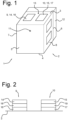
- the absorptive heat flux sensor 9 operable to absorb thermal radiation is further referred to as absorptive sensor.
- This absorptive sensor 9 measures both convective and thermal radiation.
- the reflective heat flux sensor 10 operable to reflect thermal radiation is further referred to as reflective sensor.
- the reflective sensor 10 measures predominantly convective heat flux.
- the body 2 is well conducting heat, typically made of metal with a thermal conductivity of larger than 10 W/(m ⁇ K) and a heat capacity larger than 18 J / K typically made of metals such as aluminium, brass or steel. Each side of the body 3, 4, 5, 6, 7, 8 is a predominantly flat surface with a different spatial orientation.
- the absorptive sensor 9 is typically black coated to absorb thermal radiation, the coating may be made of a black high temperature paint qualifying as high absorptivity layer 14 the heat flux sensor may be made using a thermopile sensing element encapsulated in a plastic 16, or another method measuring a temperature difference across a solid layer and presents a thermal absorptivity between 0.8 and 1.
- the absorptive sensor 9 measures both a convective and a radiative heat flux, ⁇ convection + ⁇ radiation , through its surface on the measurement side 3.
- the heating member 12 is positioned in heat conducting contact with the body 2 and may be used to heat the body 2 to a predetermined temperature or at a predetermined power. Due to the body's high thermal conductivity, typically made of aluminium, brass or steel, combined with its mass, expressed as heat capacity, it internally has a low thermal resistance and the body is uniformly heated to the predetermined temperature, T sen , via heat conduction from the heating member.
- the heating member must have the capability of heating the sensor body to a substantially uniform temperature, so that two sensor pairs per axis facing in substantially opposite directions are equally sensitive to radiative and convective heat flux.
- the temperature sensor 11 thermally coupled with the body 2 is used to measure the temperature of the body.
- the temperature sensor 11 By controlling the body 2 to a predetermined temperature via the heating member 12 and the temperature sensor 11, radiative and convective heat transfer to an object of that particular temperature T sen , relevant to a user, can be simulated and measured.
- the air temperature T air and heat transfer coefficient C tr can both be calculated, eliminating the need for a separate air temperature measurement, and improving the level of quality assurance of the heat transfer measurements:
- C tr ⁇ convection , 2 ⁇ ⁇ convection , 1 / T sen , 1 ⁇ T sen , 2 with positive heat flux from surrounding environment to the sensor, and/or
- the optional ambient air temperature sensor 13 can be also used to separately measure an air temperature.
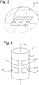
- Figure 2 shows a cross-sectional side view of the measurement plane 3, 4, 8 or 7 of the sensor 1 for measuring a heat flux of Figure 1 .
- the absorptive sensor 9 comprises, besides the high absorptivity layer 14 and the thermopile sensing element 16, a calibration heating element 18.
- the reflective sensor 10 comprises, besides the high reflectivity layer 15 and the heat flux sensing element 17, a calibration heating element 19.
- Each calibration heating element 18, 19 is placed between the high absorptivity layer 14 and the thermopile sensing element 16 or between the high reflectivity layer 15 and the heat flux sensing element 17, respectively.
- Calibration heating elements 18, 19 may be identical and/or built integrally within the absorptive and reflective sensors 9, 10. The sensitivity, surface area and electrical resistance of the calibration heating elements 18, 19 are predetermined. They allow calculation of a measured calibration heat flux for a measured output voltage over or current through the calibration heating element.
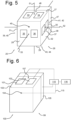
- Figure 3 shows a perspective view of the measurement surface plane 3, 4, 8 or 7 of the sensor 1 for measuring a heat flux of Fig. 1 .
- the predominantly flat measurement surface 3, 4, 8 or 7 is equipped with an absorptive sensor 9 and a reflective sensor 10 disposed at any location on the measurement surface and comprising the high absorptivity layer 14 and the high reflectivity layer 15, respectively, exposed to environmental heat fluxes.
- Each of the absorptive and reflective sensors 9, 10 have a substantially similar field of view 20, 21.
- Each field of view 20, 21 expands substantially 180 degrees in a longitudinal and in a transverse direction in an entrance plane at the measurement side 3, in other words a solid angle of 2 ⁇ sr.
- At least six sides 27, 28, 29, 30, 31, 32 are each equipped with an absorptive sensor, a reflective sensor and are further referred to as measurement sides., for the respective sensitivities to convective heat flux and absorption and reflection of thermal radiation to be comparable.
- the sensors may also be calibrated with respective calibration heating element such as shown previously in Figure 2 .
- the drawing also shows examples of pairwise perpendicular axes 51, 52, and 53 representing 6 directions of a person: up-down, left-right and front-back.
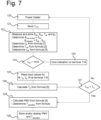
- Figure 7 shows a method of determining a thermal comfort value, in particular a predicted mean vote PMV.
- the control unit 110 comprises a processor and memory unit that calculate and store the PMV value and the operative temperature at the sensor body 100 by the following steps.
- the heater 105 is powered to set the temperature of the body 100 and sensors 101, 102 to a predetermined temperature, for example T cl in step 120.
- the sensor temperature T sen is stored in step 121.
- step 122 :
- step 123 it is determined if v air > 1m/s. If this is so, a digital, optical or acoustic warning signal is generated by the control unit 110 in step 124.
- the black globe thermometer is a device frequently used to derive an approximate value of the mean radiant temperature from the globe temperature, T g , and the temperature and the velocity of the air surrounding the globe. It also points out that the measurement with the black globe is a major source of uncertainty of the PMV measurement. Large corrections are applied. These corrections depend on the air velocity, i.e. the estimate of the velocity of natural or forced convection, which is usually not measured and thus not known, which leads to a larger measurement uncertainty than attainable with a known air velocity or direct heat flux measurements.
- the temperature of the sensor body 100 is controlled by means of the heater 106, temperature sensor 104 and the control unit 110, so that the system 99 can measure heat fluxes at the sensor pair 101, 102 at multiple different body temperatures.
- the heating member must have the capability of heating the sensor body to a substantially uniform temperature. For example, at 32 °C steady state body temperature at an air temperature between 15 and 20 °C and lower than 1 m/s air speed (typical office conditions), the temperature difference between sensors should remain below 2 °C, so that two sensor pairs per axis facing in substantially opposite directions are equally sensitive to radiative and convective heat flux.
- the local heat transfer coefficient can be estimated. From the heat transfer coefficient, the local air velocity can be calculated.
- the black coated heat flux sensor 101 measures ⁇ radiation + ⁇ convection .
- the gold coated heat flux sensor 102 measures ⁇ convection only. By subtraction, ⁇ radiation can be calculated.
- PMV is a function of 6 input parameters; metabolic rate M in W/m 2 , clothing insulation I cl , air temperature T air , mean radiant temperature T rad , relative air velocity v air and the water vapour partial pressure p a in Pa .
- One standard metabolic unit corresponds to 58.2 W/m 2 .
- the clothing insulation I cl is expressed in K ⁇ m 2 /W.
- One standard clothing unit (clo) is 0.155 K ⁇ m 2 /W, which corresponds to a typical set of garment worn in a working environment.
- the PMV can be calculated, within a certain rated operating range defining "moderate conditions", most importantly v air ⁇ 1 m/s, M ⁇ 4 met, I cl : ⁇ 2 clo, T air 10 to 30 °C.
Landscapes
- Engineering & Computer Science (AREA)
- Physics & Mathematics (AREA)
- Health & Medical Sciences (AREA)
- Life Sciences & Earth Sciences (AREA)
- General Physics & Mathematics (AREA)
- Combustion & Propulsion (AREA)
- Chemical & Material Sciences (AREA)
- Environmental & Geological Engineering (AREA)
- Physiology (AREA)
- Heart & Thoracic Surgery (AREA)
- Environmental Sciences (AREA)
- Biodiversity & Conservation Biology (AREA)
- Atmospheric Sciences (AREA)
- Computer Networks & Wireless Communication (AREA)
- Biophysics (AREA)
- Pathology (AREA)
- Biomedical Technology (AREA)
- Ecology (AREA)
- Medical Informatics (AREA)
- Molecular Biology (AREA)
- Surgery (AREA)
- Animal Behavior & Ethology (AREA)
- General Health & Medical Sciences (AREA)
- Public Health (AREA)
- Veterinary Medicine (AREA)
- Testing Or Calibration Of Command Recording Devices (AREA)
Claims (15)
- Wärmestromsensor (1, 25), umfassend:einen Körper (2, 26) mit sechs oder mehr Sensorpaaren, wobei jedes Paar aus einem strahlungsabsorbierenden, Absorptionssensor (9, 33, 35) zur Messung eines kombinierten Strahlungs- und Konvektionswärmestroms und einem strahlungsreflektierenden, Reflexionssensor (10, 34, 36) zur wesentlichen Messung eines Konvektionswärmestroms besteht,der Körper drei Achsen zur Messung des Wärmestroms aufweist, wobei die Achsen im Wesentlichen senkrecht sind und zwei Sensorpaare pro Achse im Wesentlichen in entgegengesetzte Richtungen weisen,ein Heizelement (12, 47), das in wärmeleitendem Kontakt mit dem Körper steht und dazu eingerichtet ist, den Körper gleichmäßig innerhalb von 2 °C für Körpertemperaturen zwischen 25 und 40 °C bei Umgebungslufttemperaturen zwischen 20 und 25 °C bei Luftgeschwindigkeiten < 1 m/s zu erwärmen,und einen Temperatursensor (11, 45), der thermisch mit dem Körper gekoppelt ist, um die Körpertemperatur Tsen zu messen.
- Wärmestromsensor nach Anspruch 1, der sechs oder mehr Sensorpaare mit einem kombinierten Sichtfeld (20, 21) zwischen 2,5π und 4π sr trägt.
- Wärmestromsensor nach Anspruch 1 und 2, der sechs oder mehr Sensorpaare trägt, die mit ihren Sichtfeldern in entgegengesetzte Richtungen angebracht sind und jeweils ein Sichtfeld zwischen 2π und 4π sr aufweisen.
- System umfassend den Wärmestromsensor (1, 25, 100) nach Anspruch 1 oder 2 oder 3, eine Steuereinheit (116) und einen mit der Steuereinheit verbundenen Umgebungstemperatursensor (13, 46, 107) zur Messung einer Umgebungstemperatur Tair, wobei die Steuereinheit dazu eingerichtet ist:- Betreiben des Heizelements (12, 47, 105) zur Erwärmung des Körpers,- Bestimmen oder Kontrollieren der Körpertemperatur, Tsen- Bestimmen eines Konvektionswärmestroms Φconvection aus den Messungen des Reflexionssensor jedes der sechs oder mehr Sensorpaare,- Bestimmen eines Strahlungswärmestroms Φradiation durch Subtraktion der Messwerte des Absorptionssensors und des Reflexionssensors jedes der sechs oder mehr Sensorpaare,- Bestimmen eines konvektiven Wärmeübergangskoeffizienten Ctr auf der Grundlage von Φconvection, Tair und Tsen oder auf der Grundlage der dem Heizelement bei mehreren Sensorkörpertemperaturen Tsen zugeführten Leistung,- Bestimmen einer Umgebungsluftgeschwindigkeit vair auf der Grundlage des Wärmeübergangskoeffizienten Ctr und- Bestimmen der Strahlungstemperatur Trad aus Tsen und Φradiation.
- System nach Anspruch 4, wobei die Steuereinheit die dem Heizelement zugeführte Leistung so steuert, dass der Sensorkörper auf einer vorgegebenen Temperatur Tsen gehalten wird.
- System nach Anspruch 4 oder 5, wobei der Wärmeübergangskoeffizient Ctr bestimmt wird durch


- System nach Anspruch 4 oder 5 oder 6, das ferner einen Feuchtigkeitssensor (107) umfasst, der mit der Steuereinheit verbunden ist, um eine Feuchtigkeit pa der Umgebungsluft zu bestimmen, wobei die Steuereinheit dazu eingerichtet ist, einen Komfortwert für eine Person an der Position des Sensors zu bestimmen, basierend auf:- der gemessenen Feuchtigkeit pa der Umgebungsluft,- der gemessenen Lufttemperatur Tair,- der Körpertemperatur Tsen,- dem Strahlungswärmestrom Φradiation und dem Konvektionswärmestrom Φconvection für jedes der sechs oder mehr Sensorpaare.- einer Einzelmessung mit einem Sensor nach einem der Ansprüche 1 oder 2 oder 3, der eine repräsentative Richtungsempfindlichkeit und Sichtfeld für die Person an der Position des Sensors aufweist, oder- einer Einzelmessung mit einem Sensor, der keine repräsentative Richtungsempfindlichkeit und Sichtfeld für die Person an der Position des Sensors aufweist, und unter Verwendung mathematischer Korrekturen wie projizierter Flächenfaktoren, die für die Person an der Position des Sensors gelten, oder- einer Reihe von Messungen mit Sensoren nach einem der Ansprüche 1 oder 2 oder 3, die keine repräsentative Richtungsempfindlichkeit und Sichtfeld für die Person an der Position des Sensors aufweisen, wobei der Sensor so umpositioniert wird, dass er in verschiedene Richtungen zeigt, und ein Ergebnis aus diesen Messungen berechnet wird.
- System nach Anspruch 7, wobei der Komfortwert eine erwartete durchschnittliche Empfindung PMV umfasst, die eine Funktion von Parametern ist, einschließlich einer Stoffwechselrate M, die in W/m2 ausgedrückt werden kann, der effektiven mechanischen Leistung W, die in W/m2 ausgedrückt werden kann, der Bekleidungsisolierung Ic|, die in K. m2/W ausgedrückt werden kann, die Lufttemperatur Tair, eine mittlere Strahlungstemperatur Trad, die in °C ausgedrückt werden kann, die Umgebungsluftgeschwindigkeit vair, die in m/s ausgedrückt werden kann, und die gemessene Luftfeuchtigkeit pa, die durch den Wasserdampfpartialdruck in Pa ausgedrückt werden kann, welche Parameter miteinander in Beziehung stehen:


- System nach Anspruch 4, wobei die Steuereinheit die dem Heizelement zugeführte Leistung so steuert, dass der Sensorkörper auf Tcl gehalten wird und die PMV- und PPD-Werte bei oder um Tcl gemessen werden.
- System nach einem der Ansprüche 4 bis 9, wobei die Steuereinheit dazu eingerichtet ist, die gesamte dem Körper zugeführte Heizleistung, um den Körper auf der vorgegebenen Temperatur zu halten, mit dem vom Reflexionssensor gemessenen Wärmestrom und dem vom Absorptionssensor gemessenen Wärmestrom jedes der sechs oder mehr Sensorpaare zu vergleichen.
- System nach einem der Ansprüche 4-10, wobei die Steuereinheit den Körper auf eine oder mehrere stabile Temperaturen, z. B. Tcl, erwärmt und dadurch die operative Temperatur Toperative bestimmt:

- System nach einem der Ansprüche 4-11, wobei die Steuereinheit den Körper auf eine Anzahl verschiedener Temperaturen erwärmt und aus den Strahlungswärmeströmen Φradiation und den Konvektionswärmeströmen Φconvection bei diesen Temperaturen eine Lufttemperatur, Strahlungs- und Konvektionswärmeübergangskoeffizienten und eine Betriebstemperatur bestimmt.
- System nach Anspruch 8 oder 9 in Kombination mit Anspruch 2, mit 2 oder einer anderen geraden Anzahl von Sensorpaaren, wobei die Steuereinheit einen Komfortwert, einen Strahlungswärmestrom eines Konvektionswärmestroms für jede Oberfläche, bestimmt und eine Anzeige bereitstellt, wenn ein Unterschied im Komfortwert, im Strahlungswärmestrom oder im Konvektionswärmestrom über einem vorgegebenen Schwellenwert liegt.
- Verfahren zur Bestimmung eines Komfortwerts, insbesondere einer erwarteten durchschnittlichen Empfindung PMV, wobei das Verfahren die folgenden Schritte umfasst:- Bereitstellen eines Wärmestromsensors (100) mit einem Körper (99) mit sechs oder mehr Sensorpaaren, wobei jedes Sensorpaar aus einem Absorptionssensor (101) zum Messen eines kombinierten Strahlungs- und Konvektionswärmestroms und einem Reflexionssensor (102) zum im Wesentlichen Messen eines Konvektionswärmestroms besteht, einem Heizelement (105), das in wärmeleitendem Kontakt mit dem Körper steht, einen Temperatursensor (104), der thermisch mit dem Körper gekoppelt ist, um die Körpertemperatur Tsen zu messen, und einen Feuchtigkeitssensor (107), der mit der Steuereinheit verbunden ist, um eine Feuchtigkeit pa der Umgebungsluft zu bestimmen, und einen Umgebungstemperatursensor (107), der mit der Steuereinheit verbunden ist, um eine Umgebungstemperatur Tair zu messen,- Betreiben des Heizelements zur Erwärmung des Körpers (120),- Bestimmen der Temperatur des Körpers Tsen,- Bestimmen eines Konvektionswärmestroms Φconvection für jedes der sechs oder mehr Sensorpaare aus den Messungen des reflektierenden Sensors,- Bestimmen eines Strahlungswärmestroms Φradiation durch Subtraktion der Messwerte des Absorptionssensors und des Reflexionssensors jedes der sechs oder mehr Sensorpaare,- Bestimmen eines konvektiven Wärmeübergangskoeffizienten Ctr auf der Grundlage von Φconvection, Tair und Tsen oder auf der Grundlage der dem Heizelement bei mehreren Sensorkörpertemperaturen Tsen zugeführten Leistung, und- Bestimmen einer Umgebungsluftgeschwindigkeit vair auf der Grundlage des Wärmeübergangskoeffizienten Ctr,- Eingeben der Werte von M Stoffwechselrate, W Arbeit, Icl, Isolierung der Kleidung, fcl Oberflächenfaktor der Kleidung undBestimmung des Komfortwerts auf der Grundlage:- der gemessenen Feuchtigkeit pa der Umgebungsluft,- der gemessenen Lufttemperatur Tair,- der Körpertemperatur Tsen,- des Strahlungswärmestroms Φradiation und des Konvektionswärmestroms Φcovection für jedes der sechs oder mehr Sensorpaare- einer Einzelmessung mit einem Sensor nach einem der Ansprüche 1 und 2, der eine repräsentative Richtcharakteristik und Sichtfeld für die Person an der Position des Sensors aufweist, oder- einer Reihe von Messungen mit Sensoren nach einem der Ansprüche 1 und 2, die keine repräsentative Richtungsempfindlichkeit und Sichtfeld für die Person an der Position des Sensors aufweisen, wobei der Sensor so umpositioniert wird, dass er in verschiedene Richtungen zu zeigt, und ein Ergebnis aus diesen Messungen berechnet wird.
- Verfahren nach Anspruch 14, wobei der Komfortwert eine erwartete durchschnittliche Empfindung PMV umfasst, die eine Funktion von Parametern ist, einschließlich einer Stoffwechselrate M, die in W/m2 ausgedrückt werden kann, der effektiven mechanischen Leistung W, die in W/m2 ausgedrückt werden kann, der Bekleidungsisolierung Icl, die in K.m2/W ausgedrückt werden kann, die Lufttemperatur Tair, eine mittlere Strahlungstemperatur Trad, die in °C ausgedrückt werden kann, die Umgebungsluftgeschwindigkeit vair, die in m/s ausgedrückt werden kann, und die gemessene Luftfeuchtigkeit pa, die durch den Wasserdampfpartialdruck in Pa ausgedrückt kann, wobei diese Parameter miteinander in Beziehung stehen:
PMV = [0,303 e (-0.036 M) +0,028] x [ [(M-W)- 3,05 x 10⁻³ [5733 -6,99 (M-W) - pa] -0,42 [(M-W) -58,15] - 1.7 x 10⁻⁵ M (5867 -pa) - 0,0015 M (34-Tair) - 3,96 10-8 fcl ((Tcl+ 273)4 - (Trad+273)4) - fcl Ctr (Tcl-Tair) ], 
Applications Claiming Priority (2)
| Application Number | Priority Date | Filing Date | Title |
|---|---|---|---|
| NL2028142A NL2028142B1 (en) | 2021-05-04 | 2021-05-04 | Thermal comfort measuring system |
| PCT/NL2022/050226 WO2022235153A1 (en) | 2021-05-04 | 2022-04-28 | Thermal comfort measuring system |
Publications (3)
| Publication Number | Publication Date |
|---|---|
| EP4334692A1 EP4334692A1 (de) | 2024-03-13 |
| EP4334692C0 EP4334692C0 (de) | 2025-04-09 |
| EP4334692B1 true EP4334692B1 (de) | 2025-04-09 |
Family
ID=76523417
Family Applications (1)
| Application Number | Title | Priority Date | Filing Date |
|---|---|---|---|
| EP22720523.4A Active EP4334692B1 (de) | 2021-05-04 | 2022-04-28 | System zur messung des thermischen komforts |
Country Status (5)
| Country | Link |
|---|---|
| US (1) | US20240230429A1 (de) |
| EP (1) | EP4334692B1 (de) |
| CN (1) | CN117321396A (de) |
| NL (1) | NL2028142B1 (de) |
| WO (1) | WO2022235153A1 (de) |
Families Citing this family (1)
| Publication number | Priority date | Publication date | Assignee | Title |
|---|---|---|---|---|
| KR20240005315A (ko) * | 2022-07-05 | 2024-01-12 | 현대자동차주식회사 | 팔을 거치하는 거치부의 온도 제어 시스템 및 방법 |
Family Cites Families (6)
| Publication number | Priority date | Publication date | Assignee | Title |
|---|---|---|---|---|
| GB8528517D0 (en) * | 1985-11-20 | 1985-12-24 | United Biscuits Ltd | Radiant heat measurement |
| US5216625A (en) * | 1989-11-01 | 1993-06-01 | Luxtron Corporation | Autocalibrating dual sensor non-contact temperature measuring device |
| GB2367891B (en) * | 2000-10-09 | 2004-07-07 | United Biscuits Ltd | Improvements in and relating to the measurement of heat flux in a heated chamber |
| GB2399175B (en) * | 2003-03-03 | 2006-04-12 | United Biscuits Ltd | Improvements in and relating to the measurement of heat flux in a heated chamber |
| GB201620108D0 (en) * | 2016-11-28 | 2017-01-11 | Sensor Cambridge Innovation Ltd | Oven method of controlling oven and sensors |
| US11220158B2 (en) | 2018-12-12 | 2022-01-11 | GM Global Technology Operations LLC | Vehicle with thermal comfort sensor for cabin climate control |
-
2021
- 2021-05-04 NL NL2028142A patent/NL2028142B1/en active
-
2022
- 2022-04-28 WO PCT/NL2022/050226 patent/WO2022235153A1/en not_active Ceased
- 2022-04-28 CN CN202280033124.2A patent/CN117321396A/zh active Pending
- 2022-04-28 US US18/557,534 patent/US20240230429A1/en active Pending
- 2022-04-28 EP EP22720523.4A patent/EP4334692B1/de active Active
Non-Patent Citations (2)
| Title |
|---|
| MEGGERS FORREST ET AL: "Improving Mean Radiant Temperatures Sensing Using Multidirectional Non-Contacting Temperature Sensors to Avoid Convective Errors With Globe Thermometers", 2022 IEEE INTERNATIONAL WORKSHOP ON METROLOGY FOR LIVING ENVIRONMENT (METROLIVEN), IEEE, 25 May 2022 (2022-05-25), pages 18 - 22, XP034152159, [retrieved on 20220718], DOI: 10.1109/METROLIVENV54405.2022.9826986 * |
| MEGGERS FORREST ET AL: "The Thermoheliodome - "Air conditioning" without conditioning the air, using radiant cooling and indirect evaporation", ENERGY, vol. 157, pages 11 - 19, XP085263526, ISSN: 0378-7788, DOI: 10.1016/J.ENBUILD.2017.06.033 * |
Also Published As
| Publication number | Publication date |
|---|---|
| CN117321396A (zh) | 2023-12-29 |
| EP4334692C0 (de) | 2025-04-09 |
| EP4334692A1 (de) | 2024-03-13 |
| WO2022235153A1 (en) | 2022-11-10 |
| US20240230429A1 (en) | 2024-07-11 |
| NL2028142B1 (en) | 2022-11-23 |
Similar Documents
| Publication | Publication Date | Title |
|---|---|---|
| US10154541B2 (en) | System for determining ambient temperature | |
| De Dear et al. | Convective and radiative heat transfer coefficients for individual human body segments | |
| Foda et al. | Design strategy for maximizing the energy-efficiency of a localized floor-heating system using a thermal manikin with human thermoregulatory control | |
| Mayer | Objective criteria for thermal comfort | |
| GB2249848A (en) | Control apparatus for air-conditioner | |
| Ekici | Measurement uncertainty budget of the PMV thermal comfort equation | |
| EP4334692B1 (de) | System zur messung des thermischen komforts | |
| US9976908B2 (en) | Device for temperature measurements of surfaces with a low unknown and/or variable emissivity | |
| JP2581625B2 (ja) | 温熱感覚演算方法および装置、予測平均温感演算方法および装置 | |
| US6439028B1 (en) | Method and equipment for measuring vapor flux from surfaces | |
| CN100538402C (zh) | 热舒适的传感装置以及包括多个这种装置的用于模拟热交换的模拟人 | |
| Park et al. | Thermal resistance of the segments of a human body in contact with a heated and ventilated seat | |
| EP0495117A1 (de) | Verfahren zur berechnung der äquivalenttemperatur und umwelt-messinstrument | |
| JP2588792B2 (ja) | 温熱感覚演算方法および装置 | |
| WO2022235154A1 (en) | Thermal sensor, measurement system, and method of estimating an air temperature and/or a convective heat transfer coefficient | |
| OLESEN et al. | Measurements of the physical parameters of the thermal environment | |
| Thornton et al. | Parametric studies of human thermal mechanisms and measurements | |
| Kon | Thermal comfort sensor | |
| JPH0629799B2 (ja) | 放散熱量測定装置 | |
| JP2628112B2 (ja) | 温熱感覚演算装置 | |
| Pahinkar et al. | Analytical model for human thermal comfort in passenger vehicles | |
| Najjaran et al. | Determination of Radiation Coefficient of Standing Human Body Model by Numerical Approach | |
| JPS61181916A (ja) | 温熱検知素子 | |
| Thellier et al. | Measurement of ambient air temperature for evaluation of human heat convective losses | |
| Cisternino et al. | The thermal perception-An instrument device to measure the dry thermal |
Legal Events
| Date | Code | Title | Description |
|---|---|---|---|
| STAA | Information on the status of an ep patent application or granted ep patent |
Free format text: STATUS: UNKNOWN |
|
| STAA | Information on the status of an ep patent application or granted ep patent |
Free format text: STATUS: THE INTERNATIONAL PUBLICATION HAS BEEN MADE |
|
| PUAI | Public reference made under article 153(3) epc to a published international application that has entered the european phase |
Free format text: ORIGINAL CODE: 0009012 |
|
| STAA | Information on the status of an ep patent application or granted ep patent |
Free format text: STATUS: REQUEST FOR EXAMINATION WAS MADE |
|
| 17P | Request for examination filed |
Effective date: 20231114 |
|
| AK | Designated contracting states |
Kind code of ref document: A1 Designated state(s): AL AT BE BG CH CY CZ DE DK EE ES FI FR GB GR HR HU IE IS IT LI LT LU LV MC MK MT NL NO PL PT RO RS SE SI SK SM TR |
|
| STAA | Information on the status of an ep patent application or granted ep patent |
Free format text: STATUS: EXAMINATION IS IN PROGRESS |
|
| DAV | Request for validation of the european patent (deleted) | ||
| DAX | Request for extension of the european patent (deleted) | ||
| 17Q | First examination report despatched |
Effective date: 20240801 |
|
| GRAP | Despatch of communication of intention to grant a patent |
Free format text: ORIGINAL CODE: EPIDOSNIGR1 |
|
| STAA | Information on the status of an ep patent application or granted ep patent |
Free format text: STATUS: GRANT OF PATENT IS INTENDED |
|
| INTG | Intention to grant announced |
Effective date: 20241128 |
|
| GRAS | Grant fee paid |
Free format text: ORIGINAL CODE: EPIDOSNIGR3 |
|
| GRAA | (expected) grant |
Free format text: ORIGINAL CODE: 0009210 |
|
| STAA | Information on the status of an ep patent application or granted ep patent |
Free format text: STATUS: THE PATENT HAS BEEN GRANTED |
|
| AK | Designated contracting states |
Kind code of ref document: B1 Designated state(s): AL AT BE BG CH CY CZ DE DK EE ES FI FR GB GR HR HU IE IS IT LI LT LU LV MC MK MT NL NO PL PT RO RS SE SI SK SM TR |
|
| REG | Reference to a national code |
Ref country code: GB Ref legal event code: FG4D |
|
| REG | Reference to a national code |
Ref country code: CH Ref legal event code: EP |
|
| REG | Reference to a national code |
Ref country code: DE Ref legal event code: R096 Ref document number: 602022012945 Country of ref document: DE |
|
| REG | Reference to a national code |
Ref country code: IE Ref legal event code: FG4D |
|
| U01 | Request for unitary effect filed |
Effective date: 20250423 |
|
| U07 | Unitary effect registered |
Designated state(s): AT BE BG DE DK EE FI FR IT LT LU LV MT NL PT RO SE SI Effective date: 20250430 |
|
| U20 | Renewal fee for the european patent with unitary effect paid |
Year of fee payment: 4 Effective date: 20250425 |
|
| PG25 | Lapsed in a contracting state [announced via postgrant information from national office to epo] |
Ref country code: ES Free format text: LAPSE BECAUSE OF FAILURE TO SUBMIT A TRANSLATION OF THE DESCRIPTION OR TO PAY THE FEE WITHIN THE PRESCRIBED TIME-LIMIT Effective date: 20250409 |
|
| PG25 | Lapsed in a contracting state [announced via postgrant information from national office to epo] |
Ref country code: NO Free format text: LAPSE BECAUSE OF FAILURE TO SUBMIT A TRANSLATION OF THE DESCRIPTION OR TO PAY THE FEE WITHIN THE PRESCRIBED TIME-LIMIT Effective date: 20250709 Ref country code: GR Free format text: LAPSE BECAUSE OF FAILURE TO SUBMIT A TRANSLATION OF THE DESCRIPTION OR TO PAY THE FEE WITHIN THE PRESCRIBED TIME-LIMIT Effective date: 20250710 |
|
| PG25 | Lapsed in a contracting state [announced via postgrant information from national office to epo] |
Ref country code: PL Free format text: LAPSE BECAUSE OF FAILURE TO SUBMIT A TRANSLATION OF THE DESCRIPTION OR TO PAY THE FEE WITHIN THE PRESCRIBED TIME-LIMIT Effective date: 20250409 |
|
| PG25 | Lapsed in a contracting state [announced via postgrant information from national office to epo] |
Ref country code: HR Free format text: LAPSE BECAUSE OF FAILURE TO SUBMIT A TRANSLATION OF THE DESCRIPTION OR TO PAY THE FEE WITHIN THE PRESCRIBED TIME-LIMIT Effective date: 20250409 |
|
| PG25 | Lapsed in a contracting state [announced via postgrant information from national office to epo] |
Ref country code: RS Free format text: LAPSE BECAUSE OF FAILURE TO SUBMIT A TRANSLATION OF THE DESCRIPTION OR TO PAY THE FEE WITHIN THE PRESCRIBED TIME-LIMIT Effective date: 20250709 |
|
| PG25 | Lapsed in a contracting state [announced via postgrant information from national office to epo] |
Ref country code: IS Free format text: LAPSE BECAUSE OF FAILURE TO SUBMIT A TRANSLATION OF THE DESCRIPTION OR TO PAY THE FEE WITHIN THE PRESCRIBED TIME-LIMIT Effective date: 20250809 |
|
| REG | Reference to a national code |
Ref country code: CH Ref legal event code: H13 Free format text: ST27 STATUS EVENT CODE: U-0-0-H10-H13 (AS PROVIDED BY THE NATIONAL OFFICE) Effective date: 20251125 |
|
| PG25 | Lapsed in a contracting state [announced via postgrant information from national office to epo] |
Ref country code: SM Free format text: LAPSE BECAUSE OF FAILURE TO SUBMIT A TRANSLATION OF THE DESCRIPTION OR TO PAY THE FEE WITHIN THE PRESCRIBED TIME-LIMIT Effective date: 20250409 |
|
| PG25 | Lapsed in a contracting state [announced via postgrant information from national office to epo] |
Ref country code: CH Free format text: LAPSE BECAUSE OF NON-PAYMENT OF DUE FEES Effective date: 20250430 |
|
| PG25 | Lapsed in a contracting state [announced via postgrant information from national office to epo] |
Ref country code: CZ Free format text: LAPSE BECAUSE OF FAILURE TO SUBMIT A TRANSLATION OF THE DESCRIPTION OR TO PAY THE FEE WITHIN THE PRESCRIBED TIME-LIMIT Effective date: 20250409 |
|
| PG25 | Lapsed in a contracting state [announced via postgrant information from national office to epo] |
Ref country code: SK Free format text: LAPSE BECAUSE OF FAILURE TO SUBMIT A TRANSLATION OF THE DESCRIPTION OR TO PAY THE FEE WITHIN THE PRESCRIBED TIME-LIMIT Effective date: 20250409 |
|
| PG25 | Lapsed in a contracting state [announced via postgrant information from national office to epo] |
Ref country code: MC Free format text: LAPSE BECAUSE OF FAILURE TO SUBMIT A TRANSLATION OF THE DESCRIPTION OR TO PAY THE FEE WITHIN THE PRESCRIBED TIME-LIMIT Effective date: 20250409 |
|
| PLBE | No opposition filed within time limit |
Free format text: ORIGINAL CODE: 0009261 |
|
| STAA | Information on the status of an ep patent application or granted ep patent |
Free format text: STATUS: NO OPPOSITION FILED WITHIN TIME LIMIT |
|
| REG | Reference to a national code |
Ref country code: CH Ref legal event code: L10 Free format text: ST27 STATUS EVENT CODE: U-0-0-L10-L00 (AS PROVIDED BY THE NATIONAL OFFICE) Effective date: 20260218 |
|
| 26N | No opposition filed |
Effective date: 20260112 |