EP4334178B1 - Steuervorrichtung und verfahren zum zumindest teilweisen entleeren eines flüssigkeitsspeichers eines bremssystems eines fahrzeugs - Google Patents
Steuervorrichtung und verfahren zum zumindest teilweisen entleeren eines flüssigkeitsspeichers eines bremssystems eines fahrzeugs Download PDFInfo
- Publication number
- EP4334178B1 EP4334178B1 EP22724464.7A EP22724464A EP4334178B1 EP 4334178 B1 EP4334178 B1 EP 4334178B1 EP 22724464 A EP22724464 A EP 22724464A EP 4334178 B1 EP4334178 B1 EP 4334178B1
- Authority
- EP
- European Patent Office
- Prior art keywords
- brake
- valve
- brake circuit
- wheel outlet
- fluid reservoir
- Prior art date
- Legal status (The legal status is an assumption and is not a legal conclusion. Google has not performed a legal analysis and makes no representation as to the accuracy of the status listed.)
- Active
Links
Images



Classifications
-
- B—PERFORMING OPERATIONS; TRANSPORTING
- B60—VEHICLES IN GENERAL
- B60T—VEHICLE BRAKE CONTROL SYSTEMS OR PARTS THEREOF; BRAKE CONTROL SYSTEMS OR PARTS THEREOF, IN GENERAL; ARRANGEMENT OF BRAKING ELEMENTS ON VEHICLES IN GENERAL; PORTABLE DEVICES FOR PREVENTING UNWANTED MOVEMENT OF VEHICLES; VEHICLE MODIFICATIONS TO FACILITATE COOLING OF BRAKES
- B60T8/00—Arrangements for adjusting wheel-braking force to meet varying vehicular or ground-surface conditions, e.g. limiting or varying distribution of braking force
- B60T8/32—Arrangements for adjusting wheel-braking force to meet varying vehicular or ground-surface conditions, e.g. limiting or varying distribution of braking force responsive to a speed condition, e.g. acceleration or deceleration
- B60T8/34—Arrangements for adjusting wheel-braking force to meet varying vehicular or ground-surface conditions, e.g. limiting or varying distribution of braking force responsive to a speed condition, e.g. acceleration or deceleration having a fluid pressure regulator responsive to a speed condition
- B60T8/36—Arrangements for adjusting wheel-braking force to meet varying vehicular or ground-surface conditions, e.g. limiting or varying distribution of braking force responsive to a speed condition, e.g. acceleration or deceleration having a fluid pressure regulator responsive to a speed condition including a pilot valve responding to an electromagnetic force
- B60T8/3615—Electromagnetic valves specially adapted for anti-lock brake and traction control systems
- B60T8/363—Electromagnetic valves specially adapted for anti-lock brake and traction control systems in hydraulic systems
- B60T8/365—Electromagnetic valves specially adapted for anti-lock brake and traction control systems in hydraulic systems combining a plurality of functions in one unit, e.g. pressure relief
-
- B—PERFORMING OPERATIONS; TRANSPORTING
- B60—VEHICLES IN GENERAL
- B60T—VEHICLE BRAKE CONTROL SYSTEMS OR PARTS THEREOF; BRAKE CONTROL SYSTEMS OR PARTS THEREOF, IN GENERAL; ARRANGEMENT OF BRAKING ELEMENTS ON VEHICLES IN GENERAL; PORTABLE DEVICES FOR PREVENTING UNWANTED MOVEMENT OF VEHICLES; VEHICLE MODIFICATIONS TO FACILITATE COOLING OF BRAKES
- B60T13/00—Transmitting braking action from initiating means to ultimate brake actuator with power assistance or drive; Brake systems incorporating such transmitting means, e.g. air-pressure brake systems
- B60T13/10—Transmitting braking action from initiating means to ultimate brake actuator with power assistance or drive; Brake systems incorporating such transmitting means, e.g. air-pressure brake systems with fluid assistance, drive, or release
- B60T13/12—Transmitting braking action from initiating means to ultimate brake actuator with power assistance or drive; Brake systems incorporating such transmitting means, e.g. air-pressure brake systems with fluid assistance, drive, or release the fluid being liquid
- B60T13/14—Transmitting braking action from initiating means to ultimate brake actuator with power assistance or drive; Brake systems incorporating such transmitting means, e.g. air-pressure brake systems with fluid assistance, drive, or release the fluid being liquid using accumulators or reservoirs fed by pumps
- B60T13/142—Systems with master cylinder
-
- B—PERFORMING OPERATIONS; TRANSPORTING
- B60—VEHICLES IN GENERAL
- B60T—VEHICLE BRAKE CONTROL SYSTEMS OR PARTS THEREOF; BRAKE CONTROL SYSTEMS OR PARTS THEREOF, IN GENERAL; ARRANGEMENT OF BRAKING ELEMENTS ON VEHICLES IN GENERAL; PORTABLE DEVICES FOR PREVENTING UNWANTED MOVEMENT OF VEHICLES; VEHICLE MODIFICATIONS TO FACILITATE COOLING OF BRAKES
- B60T13/00—Transmitting braking action from initiating means to ultimate brake actuator with power assistance or drive; Brake systems incorporating such transmitting means, e.g. air-pressure brake systems
- B60T13/10—Transmitting braking action from initiating means to ultimate brake actuator with power assistance or drive; Brake systems incorporating such transmitting means, e.g. air-pressure brake systems with fluid assistance, drive, or release
- B60T13/66—Electrical control in fluid-pressure brake systems
- B60T13/662—Electrical control in fluid-pressure brake systems characterised by specified functions of the control system components
-
- B—PERFORMING OPERATIONS; TRANSPORTING
- B60—VEHICLES IN GENERAL
- B60T—VEHICLE BRAKE CONTROL SYSTEMS OR PARTS THEREOF; BRAKE CONTROL SYSTEMS OR PARTS THEREOF, IN GENERAL; ARRANGEMENT OF BRAKING ELEMENTS ON VEHICLES IN GENERAL; PORTABLE DEVICES FOR PREVENTING UNWANTED MOVEMENT OF VEHICLES; VEHICLE MODIFICATIONS TO FACILITATE COOLING OF BRAKES
- B60T13/00—Transmitting braking action from initiating means to ultimate brake actuator with power assistance or drive; Brake systems incorporating such transmitting means, e.g. air-pressure brake systems
- B60T13/10—Transmitting braking action from initiating means to ultimate brake actuator with power assistance or drive; Brake systems incorporating such transmitting means, e.g. air-pressure brake systems with fluid assistance, drive, or release
- B60T13/66—Electrical control in fluid-pressure brake systems
- B60T13/68—Electrical control in fluid-pressure brake systems by electrically-controlled valves
- B60T13/686—Electrical control in fluid-pressure brake systems by electrically-controlled valves in hydraulic systems or parts thereof
-
- B—PERFORMING OPERATIONS; TRANSPORTING
- B60—VEHICLES IN GENERAL
- B60T—VEHICLE BRAKE CONTROL SYSTEMS OR PARTS THEREOF; BRAKE CONTROL SYSTEMS OR PARTS THEREOF, IN GENERAL; ARRANGEMENT OF BRAKING ELEMENTS ON VEHICLES IN GENERAL; PORTABLE DEVICES FOR PREVENTING UNWANTED MOVEMENT OF VEHICLES; VEHICLE MODIFICATIONS TO FACILITATE COOLING OF BRAKES
- B60T8/00—Arrangements for adjusting wheel-braking force to meet varying vehicular or ground-surface conditions, e.g. limiting or varying distribution of braking force
- B60T8/32—Arrangements for adjusting wheel-braking force to meet varying vehicular or ground-surface conditions, e.g. limiting or varying distribution of braking force responsive to a speed condition, e.g. acceleration or deceleration
- B60T8/34—Arrangements for adjusting wheel-braking force to meet varying vehicular or ground-surface conditions, e.g. limiting or varying distribution of braking force responsive to a speed condition, e.g. acceleration or deceleration having a fluid pressure regulator responsive to a speed condition
- B60T8/48—Arrangements for adjusting wheel-braking force to meet varying vehicular or ground-surface conditions, e.g. limiting or varying distribution of braking force responsive to a speed condition, e.g. acceleration or deceleration having a fluid pressure regulator responsive to a speed condition connecting the brake actuator to an alternative or additional source of fluid pressure, e.g. traction control systems
- B60T8/4809—Traction control, stability control, using both the wheel brakes and other automatic braking systems
- B60T8/4827—Traction control, stability control, using both the wheel brakes and other automatic braking systems in hydraulic brake systems
- B60T8/4863—Traction control, stability control, using both the wheel brakes and other automatic braking systems in hydraulic brake systems closed systems
- B60T8/4872—Traction control, stability control, using both the wheel brakes and other automatic braking systems in hydraulic brake systems closed systems pump-back systems
-
- B—PERFORMING OPERATIONS; TRANSPORTING
- B60—VEHICLES IN GENERAL
- B60T—VEHICLE BRAKE CONTROL SYSTEMS OR PARTS THEREOF; BRAKE CONTROL SYSTEMS OR PARTS THEREOF, IN GENERAL; ARRANGEMENT OF BRAKING ELEMENTS ON VEHICLES IN GENERAL; PORTABLE DEVICES FOR PREVENTING UNWANTED MOVEMENT OF VEHICLES; VEHICLE MODIFICATIONS TO FACILITATE COOLING OF BRAKES
- B60T2270/00—Further aspects of brake control systems not otherwise provided for
- B60T2270/60—Regenerative braking
- B60T2270/604—Merging friction therewith; Adjusting their repartition
Definitions
- the invention relates to a control device for a braking system of a vehicle with at least one brake circuit comprising a fluid reservoir.
- the invention also relates to a braking system for a vehicle.
- the invention relates to a method for at least partially emptying a brake fluid reservoir of a braking system of a vehicle.
- the disclosure DE 10 2019 207 608 A1 discloses a control device for a braking system of a vehicle, which is designed to detect or estimate, based on at least one sensor signal provided to the control device from at least one sensor, whether a driver braking force exerted on a brake actuating element connected to a master brake cylinder of the braking system decreases over time.
- the control device is also designed to control and/or maintain a high-pressure switching valve of a brake circuit connected to the master brake cylinder with at least one wheel brake cylinder, via which a storage chamber of the brake circuit is connected to the master brake cylinder, in its open state, at least temporarily during a detected or estimated decrease in the driver braking force, so that brake fluid can be transferred from the storage chamber into the master brake cylinder via the high-pressure switching valve in its open state.
- the invention provides a control device for a braking system of a vehicle with at least one brake circuit comprising a fluid reservoir with the features of claim 1, a braking system for a vehicle with the features of claim 4 and a method for at least partially emptying a fluid reservoir of a braking system of a vehicle with the features of claim 8.
- the present invention provides advantageous possibilities for at least partially emptying a fluid reservoir of a vehicle's brake system while simultaneously limiting or preventing a brake fluid flow through the single wheel outlet valve or all wheel outlet valves of a brake circuit of the brake system formed with the at least emptied fluid reservoir.
- This eliminates the conventional need to provide the at least one wheel outlet valve of the brake circuit formed with the fluid reservoir to be emptied with a own filter for a brake fluid transfer from the fluid reservoir through the respective valve, such as a net filter or mesh filter.
- a net filter or mesh filter such as a net filter or mesh filter.
- Use of the present invention thus increases design freedom for the at least one wheel outlet valve of the brake circuit formed with the fluid reservoir. In addition, this can contribute to reducing the types of outlet valve used when producing a brake system using the present invention.
- the electronic device is designed and/or programmed to control or keep the changeover valve of the brake circuit in its closed state during the entire opening time. Controlling the changeover valve closed or keeping it closed advantageously contributes to preventing the undesirable transfer of brake fluid from the fluid reservoir through the at least one wheel outlet valve of the brake circuit during the opening time.
- the electronic device can also be designed and/or programmed to control and/or maintain the only wheel outlet valve of the brake circuit or the at least one of the wheel outlet valves of the brake circuit, which due to its design and orientation is permeable to brake fluid from the fluid reservoir in an at least partially open state, in its closed state during the entire opening time.
- the undesirable transfer of brake fluid from the fluid reservoir through the at least one wheel outlet valve can also be prevented during the entire opening time by means of such a design/programming of the control device/its electronic device.
- a braking system for a vehicle which is designed with a corresponding control device and at least the brake circuit connected to the master brake cylinder of the braking system with the fluid reservoir and the high-pressure switching valve which can be controlled by means of the electronic device of the control device, wherein the brake circuit additionally also has the switching valve, the single wheel outlet valve and/or the wheel outlet valves, and wherein the changeover valve, the single wheel outlet valve and/or the wheel outlet valves can be controlled by means of the electronic device.
- the single wheel outlet valve or the wheel outlet valves each have only one filter for a brake fluid transfer from a wheel brake cylinder assigned to the respective valve to the fluid reservoir.
- the single wheel outlet valve or the wheel outlet valves are each filterless for the brake fluid transfer from the fluid reservoir through the respective valve. This contributes to reducing the manufacturing costs of the at least one wheel outlet valve of the brake circuit formed with the fluid reservoir to be emptied, and thus makes the brake system more cost-effective.
- the brake circuit can comprise a first wheel outlet valve and a second wheel outlet valve as its wheel outlet valves, wherein a first line section of the brake circuit opening at the master brake cylinder branches off to the switching valve and to the high-pressure switching valve, a second line section of the brake circuit opening at the switching valve branches off to a first wheel inlet valve and a second wheel inlet valve, a first wheel brake cylinder is connected or can be connected to a third line section of the brake circuit, which branches off to the first wheel inlet valve and the first wheel outlet valve, a second wheel brake cylinder is connected or can be connected to a fourth line section of the brake circuit, which branches off to the second wheel inlet valve and the second wheel outlet valve, a fifth line section of the brake circuit opening at an intake side of a pump device of the brake circuit branches off to the first wheel outlet valve and the second wheel outlet valve, the fluid reservoir is connected to the fifth line section is connected, a sixth line section of the brake circuit opening at a delivery side of the pump device opens at the second line section and a
- Fig. 1 shows a schematic representation of an embodiment of the control device or a braking system interacting therewith.
- the control device 10 described below can interact with (almost) any braking system which has at least one braking circuit 12a and 12b which is connected to a master brake cylinder 14 of the braking system is connected, is designed with a liquid reservoir 16a or 16b and a high-pressure switching valve 18a or 18b, and which additionally comprises a changeover valve 20a or 20b and/or at least one wheel outlet valve 22a, 22b, 24a and 24b.
- the usability of the control device 10 is not restricted to any specific vehicle type/motor vehicle type of the vehicle/motor vehicle equipped with the respective braking system.
- the control device 10 has an electronic device 26 which is designed and/or programmed to switch the high-pressure switching valve 18a or 18b of the brake circuit 12a or 12b equipped with the fluid reservoir 16a or 16b to be emptied into an at least partially open state for a predetermined or fixed opening time by means of at least one control signal 18s.
- the control device 10/its electronic device 26 ensures that during the opening time brake fluid can be transferred/flows from the fluid reservoir 16a or 16b via the at least partially opened high-pressure switching valve 18a or 18b of the same brake circuit 12a or 12b into the master brake cylinder 14.
- the volume balance of the brake system can thus be balanced by means of the control device 10/its electronic device 26 by at least partially emptying the fluid reservoir 16a or 16b.
- the electronic device 26 is additionally designed and/or programmed to control and/or maintain the switching valve 20a or 20b of the brake circuit 12a or 12b formed with the fluid reservoir 16a or 16b to be emptied, the only wheel outlet valve of the respective brake circuit 12a or 12b and/or all wheel outlet valves 22a, 22b, 24a and 24b of the respective brake circuit 12a or 12b during the entire opening time by means of at least one control signal 20s and 22s in a state in which a brake fluid transfer from the respective fluid reservoir 16a or 16b is blocked by the respective valve 20a, 20b, 22a, 22b, 24a and 24b.
- the control device 10/its electronic device 26 thus limits at least one undesirable brake fluid flow from the fluid reservoir 16a or 16b through the at least one wheel outlet valve 22a, 22b, 24a and 24b of the respective brake circuit 12a or 12b. If the electronic device 26 is designed and/or programmed to control the only wheel outlet valve of the respective brake circuit 12a or 12b or to control and/or maintain all wheel outlet valves 22a, 22b, 24a and 24b of the respective brake circuit 12a or 12b in the state blocking a brake fluid transfer from the respective fluid reservoir 16a or 16b through the respective valve 22a, 22b, 24a and 24b during the entire opening time, the undesirable brake fluid flow from the fluid reservoir 16a or 16b can also be (almost) completely prevented by the at least one wheel outlet valve 22a, 22b, 24a and 24b.
- the single wheel outlet valve or the wheel outlet valves 22a, 22b, 24a and 24b each have only one filter 23a, 23b, 25a and 25b for a brake fluid transfer from a wheel brake cylinder 28a, 28b, 30a and 30b assigned to the respective valve 22a, 22b, 24a and 24b to the fluid reservoir 16a or 16b.
- This can also be described as the single wheel outlet valve or the wheel outlet valves 22a, 22b, 24a and 24b each having no filter for the brake fluid transfer from the fluid reservoir 16a or 16b through the respective valve 22a, 22b, 24a and 24b. This reduces the manufacturing costs for the at least one wheel outlet valve 22a, 22b, 24a or 24b of the braking system interacting with the control device 10 and facilitates its manufacturability.
- a separate filter for brake fluid transfer from the fluid reservoir 16a or 16b through the respective wheel outlet valve 22a, 22b, 24a or 24b allows more freedom in the design of the respective wheel outlet valve 22a, 22b, 24a or 24b of the brake circuit 12a or 12b formed with the fluid reservoir 16a or 16b. This can be used to reduce the types of outlet valves used when manufacturing the respective brake system.
- the electronic device 26 is designed and/or programmed to control or maintain the changeover valve 20a or 20b of the brake circuit 12a or 12b in its closed state during the entire opening time of the high-pressure switching valve 18a or 18b of the same brake circuit 12a or 12b.
- the switching valve 20a or 20b controlled or held in its closed state is understood to mean a valve 20a or 20b which, due to its design and orientation, is permeable to brake fluid from the fluid reservoir 16a or 16b and through the at least one wheel outlet valve 22a, 22b, 24a and 24b of the brake circuit 12a or 12b in an at least partially open state.
- the advantages described above are also ensured if the electronic device 26 is designed and/or programmed to control the only wheel outlet valve of the brake circuit 12a or 12b or the at least one of the wheel outlet valves 22a, 22b, 24a and 24b of the brake circuit 12a or 12b, which due to its design and orientation is permeable to brake fluid from the fluid reservoir 16a or 16b in an at least partially open state, during the entire opening time. of the high-pressure switching valve 18a or 18b of the same brake circuit 12a or 12b in its closed state.
- the opening time during which the high-pressure switching valve 18a or 18b of the brake circuit 12a or 12b with the liquid reservoir 16a or 16b to be emptied is/is controlled into its at least partially open state can be (fixedly) specified by the electronic device 26.
- the electronic device 26 can also be designed and/or programmed to (itself) specify the opening time, for example taking into account a reservoir pressure present in the liquid reservoir 16a or 16b to be emptied.
- the determination of the opening time by the electronic device 26 can also be understood as waiting until a predetermined event ends the opening time.
- the electronic device 26 can be designed and/or programmed to "wait" for the opening time until the driver presses the brake pedal again and/or until the accumulator pressure in the fluid reservoir 16a or 16b is increased by the flow of brake fluid from the fluid reservoir 16a or 16b via the at least partially opened high-pressure switching valve 18a or 18b of the same brake circuit 12a or 12b into the master brake cylinder 14. less than or equal to a response pressure of the respective liquid reservoir 16a or 16b.
- the fluid reservoir 16a or 16b to be emptied can be a reservoir chamber 16a and 16b integrated into the hydraulics of the respective brake system, especially a low-pressure reservoir chamber 16a and 16b.
- the use of the control device 10 is not limited to any specific fluid reservoir type.
- the control device 10/its electronic device 26 can also be designed for the simultaneous emptying of several fluid reservoirs 16a and 16b of several brake circuits 12a and 12b of the same brake system.
- the braking system of the Fig. 1 two brake circuits 12a and 12b, each with a first wheel brake cylinder 28a or 28b and a second wheel brake cylinder 30a or 30b.
- each of the brake circuits 12a and 12b is equipped with a first wheel outlet valve 22a or 22b and a second wheel outlet valve 24a or 24b as its wheel outlet valves 22a, 22b, 24a and 24b.
- Each of the brake circuits 12a and 12b has a first line section 32a or 32b which opens into the master brake cylinder 14 and branches off to its changeover valve 20a or 20b and to its high-pressure switching valve 18a or 18b.
- a second line section 34a or 34b of the respective brake circuit 12a or 12b which opens into the changeover valve 20a or 20b, branches off to a first wheel inlet valve 36a or 36b and its second wheel inlet valve 38a or 38b.
- the first wheel brake cylinder 28a or 28b is connected/can be connected to a third line section 40a or 40b of the respective brake circuit 12a or 12b, which branches off to the first wheel inlet valve 36a or 36b and the first wheel outlet valve 22a or 22b.
- the second wheel brake cylinder 30a or 30b is connected/can be connected to a fourth line section 42a or 42b of the same brake circuit 12a or 12b, which branches off to the second wheel inlet valve 38a or 38b and the second wheel outlet valve 24a or 24b.
- a fifth line section 46a or 46b which opens onto a suction side of a pump device 44a or 44b of the respective brake circuit 12a or 12b, branches off to the first wheel outlet valve 22a or 22b and the second wheel outlet valve 24a or 24b, wherein the fluid reservoir 16a or 16b of the respective brake circuit 12a or 12b is connected to the fifth line section 46a or 46b.
- a sixth line section 48a or 48b of the respective brake circuit 12a or 12b which opens onto a delivery side of the pump device 44a or 44b, additionally opens onto the second line section 34a or 34b.
- a seventh line section 50a or 50b of the respective brake circuit 12a or 12b opens onto the high-pressure switching valve 18a or 18b and onto the fifth line section 46a or 46b.
- At least one pressure relief valve 52a or 52b can be inserted between the fluid reservoir 16a or 16b and the pump device 44a or 44b in the fifth line section 46a or 46b.
- a filter 54a or 54b, a throttle 56a or 56b and/or a check valve 58a or 58b can also be arranged in the sixth line section 48a or 48b.
- a brake fluid reservoir 60 is connected to the master brake cylinder 14.
- a brake booster 62 can also be arranged upstream of the master brake cylinder 14.
- at least one pre-pressure sensor 64 and/or a pressure sensor can be connected to at least one of the brake circuits 12a and 12b.
- Fig. 2a to 2d show a flow chart, a time diagram and schematic partial representations of a braking system for explaining a first embodiment of the method for at least partially emptying a fluid reservoir of a braking system of a vehicle.
- any braking system which has at least one braking circuit 12a which is connected to a master brake cylinder 14 of the braking system, is designed with a fluid reservoir 16a and a high-pressure switching valve 18a, and which additionally comprises a switching valve 20a and/or at least one wheel outlet valve 22a and 24a.
- the executability of the method is not restricted to any specific vehicle type/motor vehicle type of the vehicle/motor vehicle equipped with the respective braking system.
- the "pictorial representation" of the method using at least the first braking circuit 12a and the master brake cylinder 14 of the braking system of the Fig. 1 is only for better understanding.
- step S1 emptying of the fluid reservoir is preceded by an optional method step S1, which can also be omitted.
- method step S1 it is examined whether an adjustment path x of a brake pedal 66 connected to the master brake cylinder 14, caused by a driver braking force F, from its unactuated initial position is not equal to zero, whether a time derivative of the adjustment path x is greater than or equal to zero and whether a target braking torque M 0 corresponding to the adjustment path x can be implemented as a generator braking torque M gen by means of at least one recuperatively operated electric motor of the vehicle.
- the adjustment path x can be measured, for example, by means of a rod travel sensor 68.
- the target braking torque M 0 the generator braking torque M gen
- a volume V present in a fluid reservoir 16a of the first brake circuit 12a an opening state of a first wheel outlet valve 22a of the first brake circuit 12a and an opening state of a high-pressure switching valve 18a of the first brake circuit 12a are shown along a time axis t.
- a method step S2 is carried out, which Fig. 2c is shown schematically.
- a changeover valve 20a of the first brake circuit 12a, a first wheel inlet valve 36a assigned to a first wheel brake cylinder 28a of the first brake circuit 12a and the first wheel outlet valve 22a assigned to the first wheel brake cylinder 28a are controlled and/or held in an at least partially open state ⁇ o such that, as is illustrated by the arrows 70, the brake fluid pressed out of the master brake cylinder 14 by the driver's braking force F is displaced via the changeover valve 20a, the first wheel inlet valve 36a and the first wheel outlet valve 22a into the fluid reservoir 16a.
- a second wheel inlet valve 38a associated with a second wheel brake cylinder 30a of the first brake circuit 12a and a second wheel outlet valve 24a of the first brake circuit 12a associated with the second wheel brake cylinder 30a are simultaneously controlled and/or held in a closed state, whereby a brake fluid transfer into the second Wheel brake cylinder 30a is prevented.
- a first brake pressure equal to a response pressure of the fluid reservoir 16a is present in the first wheel brake cylinder 28a
- a second brake pressure present in the second wheel brake cylinder 30a can be kept (almost) equal to the atmospheric pressure.
- the high-pressure switching valve 18a is also controlled/held in its closed state ⁇ c.
- the method step S2 is also continued after the time derivative of the adjustment path x becomes equal to zero at time t1.
- a further optional method step S3 examines whether at least partial emptying of the fluid reservoir 16a is desirable. For example, this can be done by determining whether the first brake pressure present in the first wheel brake cylinder 28a is below a storage pressure present in the fluid reservoir 16a. If this is not the case, method step S2 is continued. Otherwise, the fluid reservoir 16a is at least partially emptied.
- the at least partial emptying of the liquid reservoir 16a begins from time t2:
- the high-pressure switching valve 18a is controlled for a predetermined or fixed opening time into an at least partially opened state ⁇ o such that, as indicated by an arrow 72 in Fig. 2d is illustrated, during the opening time brake fluid flows from the fluid reservoir 16a via the at least partially opened high-pressure switching valve 18a into the master brake cylinder 14.
- a method step S5 is also carried out in which the switching valve 20a of the first brake circuit 12a, the only wheel outlet valve of the first brake circuit 12a and/or all wheel outlet valves 22a and 22b of the first brake circuit 12a are controlled or maintained during the entire opening time in a state in which a brake fluid transfer from the fluid reservoir 16a is blocked by the respective valve 20a, 22a and 24a.
- the first wheel outlet valve 22a of the first brake circuit 12a which, due to its design and orientation, is permeable to brake fluid from the fluid reservoir 16a in an at least partially open state ⁇ o, is controlled to its closed state ⁇ c during the entire opening time.
- the second wheel outlet valve 24a of the first brake circuit 12a is kept in its closed state ⁇ c during the entire opening time.
- step S5a a transfer of brake fluid from the fluid reservoir 16a through the outlet valves 22a and 24a of the brake circuit 12a is completely prevented.
- the opening time can be understood as a fixed opening time.
- the opening time can also be self-determined.
- the opening time can be determined taking into account a pressure difference between the accumulator pressure present in the fluid reservoir 16a minus the first brake pressure present in the first wheel brake cylinder 28a.
- the opening time can also be "waited” until at least one predetermined event occurs.
- the opening time can be "waited” until the time derivative of the adjustment path x of the brake pedal 66 is greater than or equal to zero and/or until the accumulator pressure in the fluid reservoir 16a is less than or equal to the response pressure.
- the time diagram shows the Fig. 2b that when the adjustment path x of the brake pedal 66 subsequently increases from time t3, the first wheel outlet valve 22a is opened again, while the high-pressure switching valve 18a can remain in its at least partially open state ⁇ o.
- the volume V present in the fluid reservoir 16a can be transferred from the fluid reservoir 16a into the master brake cylinder 14 via the high-pressure switching valve 18a in its at least partially open state ⁇ o by again controlling the first wheel outlet valve 22a into its closed state ⁇ c.
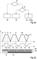
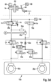
- Fig. 3a to 3d show a flow chart, a time diagram and schematic partial representations of a braking system for explaining a second Embodiment of the method for at least partially emptying a fluid reservoir of a braking system of a vehicle.
- the driver can use his driver braking force F to move the brake fluid pressed out of the master brake cylinder 14 into the fluid reservoir 16a via the check valve 21a arranged/constructed parallel to the switch valve 20a, the at least partially open first wheel inlet valve 36a and the at least partially open first wheel outlet valve 22a, with a later increase in the adjustment path x of the brake pedal 66 from time t3, despite the presence of the switch valve 20a in its closed state ⁇ c.
- the switch valve 20a can therefore remain open for the entire time determined by the flow diagram after it has closed at time t2.
- Fig. 3b reproduced braking in its closed state ⁇ c.
- the first wheel outlet valve 22a can also remain in its at least partially open state ⁇ o during the entire braking after it has opened at time t0.
Landscapes
- Engineering & Computer Science (AREA)
- Transportation (AREA)
- Mechanical Engineering (AREA)
- Physics & Mathematics (AREA)
- Fluid Mechanics (AREA)
- Electromagnetism (AREA)
- Regulating Braking Force (AREA)
- Braking Systems And Boosters (AREA)
Description
- Die Erfindung betrifft eine Steuervorrichtung für ein Bremssystem eines Fahrzeugs mit zumindest einem einen Flüssigkeitsspeicher umfassenden Bremskreis. Ebenso betrifft die Erfindung ein Bremssystem für ein Fahrzeug. Des Weiteren betrifft die Erfindung ein Verfahren zum zumindest teilweisen Entleeren eines Bremsflüssigkeitsspeichers eines Bremssystems eines Fahrzeugs.
- Aus dem Stand der Technik, wie beispielsweise der
DE 10 2019 211 236 A1 , sind verschiedene Bremssystemtypen bekannt, wobei ein derartiges Bremssystem zumindest einen Bremskreis mit einem Flüssigkeitsspeicher aufweist. - Die Offenlegung
DE 10 2019 207 608 A1 offenbart eine Steuervorrichtung für ein Bremssystem eines Fahrzeugs, welche dazu ausgelegt ist, anhand mindestens eines an die Steuervorrichtung bereitgestellten Sensorsignals mindestens eines Sensors zu erkennen oder zu schätzen, ob eine auf ein an einem Hauptbremszylinder des Bremssystems angebundenes Bremsbetätigungselement ausgeübte Fahrerbremskraft zeitlich abnimmt. Die Steuervorrichtung ist auch dazu ausgelegt, zumindest zeitweise während einer erkannten oder geschätzten zeitlichen Abnahme der Fahrerbremskraft ein Hochdruckschaltventil eines an dem Hauptbremszylinder angebundenen Bremskreises mit zumindest einem Radbremszylinder, über welches eine Speicherkammer des Bremskreises mit dem Hauptbremszylinder verbunden ist, in seinen offenen Zustand zu steuern und/oder zu halten, so dass Bremsflüssigkeit aus der Speicherkammer über das in seinem offenen Zustand vorliegende Hochdruckschaltventil in den Hauptbremszylinder transferierbar ist. - Die Erfindung schafft eine Steuervorrichtung für ein Bremssystem eines Fahrzeugs mit zumindest einem einen Flüssigkeitsspeicher umfassenden Bremskreis mit den Merkmalen des Anspruchs 1, ein Bremssystem für ein Fahrzeug mit den Merkmalen des Anspruchs 4 und ein Verfahren zum zumindest teilweisen Entleeren eines Flüssigkeitsspeichers eines Bremssystems eines Fahrzeugs mit den Merkmalen des Anspruchs 8.
- Die vorliegende Erfindung schafft vorteilhafte Möglichkeiten zum zumindest teilweisen Entleeren eines Flüssigkeitsspeichers eines Bremssystems eines Fahrzeugs bei gleichzeitiger Begrenzung oder Verhinderung eines Bremsflüssigkeitsstroms durch das einzige Radauslassventil oder alle Radauslassventile eines mit dem zumindest entleerten Flüssigkeitsspeicher ausgebildeten Bremskreises des Bremssystems. Damit entfällt die herkömmliche Notwendigkeit, das mindestens eine Radauslassventil des mit dem zu entleerenden Flüssigkeitsspeicher ausgebildeten Bremskreises mit je einem eigenen Filter für einen Bremsflüssigkeitstransfer aus dem Flüssigkeitsspeicher durch das jeweilige Ventil, wie beispielsweise einen Netzfilter oder Maschenfilter (Mesh Filter), auszustatten. Dies ermöglicht eine kostengünstigere Herstellbarkeit des mindestens einen Radauslassventils des mit dem zu entleerenden Flüssigkeitsspeicher ausgebildeten Bremskreises. Eine Nutzung der vorliegenden Erfindung steigert damit eine Designfreiheit für das mindestens eine Radauslassventil des mit dem Flüssigkeitsspeicher ausgebildeten Bremskreises. Zusätzlich kann dies bei einer Herstellung eines die vorliegende Erfindung anwendenden Bremssystems zur Reduzierung der eingesetzten Auslassventiltypen beitragen.
- Bei einer vorteilhaften Ausführungsform der Steuervorrichtung ist die Elektronikeinrichtung dazu ausgelegt und/oder programmiert, das Umschaltventil des Bremskreises während der gesamten Öffnungszeit in seinen geschlossenen Zustand zu steuern oder zu halten. Ein Geschlossensteuern oder Geschlossenhalten des Umschaltventils trägt vorteilhaft zur Verhinderung des während der Öffnungszeit unerwünschten Bremsflüssigkeitstransfers aus dem Flüssigkeitsspeicher durch das mindestens eine Radauslassventil des Bremskreises bei.
- Alternativ oder ergänzend kann die Elektronikeinrichtung auch dazu ausgelegt und/oder programmiert sein, das einzige Radauslassventil des Bremskreises oder das mindestens eine der Radauslassventile des Bremskreises, welches aufgrund seiner Auslegung und seiner Ausrichtung in einem zumindest teilweise geöffneten Zustand für Bremsflüssigkeit aus dem Flüssigkeitsspeicher durchlässig ist, während der gesamten Öffnungszeit in seinen geschlossenen Zustand zu steuern und/oder zu halten. Auch mittels einer derartigen Ausbildung/Programmierung der Steuervorrichtung/ihrer Elektronikeinrichtung kann der unerwünschte Bremsflüssigkeitstransfer aus dem Flüssigkeitsspeicher durch das mindestens eine Radauslassventil während der gesamten Öffnungszeit unterbunden werden.
- Die vorausgehend beschriebenen Vorteile sind auch bei einem Bremssystem für ein Fahrzeug gewährleistet, welches mit einer entsprechenden Steuervorrichtung und zumindest dem an dem Hauptbremszylinder des Bremssystems angebundenen Bremskreis mit dem Flüssigkeitsspeicher und dem mittels der Elektronikeinrichtung der Steuervorrichtung ansteuerbaren Hochdruckschaltventil ausgebildet ist, wobei der Bremskreis zusätzlich noch das Umschaltventil, das einzige Radauslassventil und/oder die Radauslassventile umfasst, und wobei das Umschaltventil, das einzige Radauslassventil und/oder die Radauslassventile mittels der Elektronikeinrichtung ansteuerbar sind.
- Vorzugsweise weisen das einzige Radauslassventil oder die Radauslassventile nur je einen Filter für einen Bremsflüssigkeitstransfer von einem dem jeweiligen Ventil zugeordneten Radbremszylinder zu dem Flüssigkeitsspeicher auf. Bevorzugter Weise ist/sind somit das einzige Radauslassventil oder die Radauslassventile jeweils für den Bremsflüssigkeitstransfer aus dem Flüssigkeitsspeicher durch das jeweilige Ventil filterlos. Dies trägt zur Reduzierung der Herstellungskosten des mindestens einen Radauslassventils des mit dem zu entleerenden Flüssigkeitsspeicher ausgebildeten Bremskreises bei, und macht damit das Bremssystem kostengünstiger.
- Beispielsweise kann der Bremskreis ein erstes Radauslassventil und ein zweites Radauslassventil als seine Radauslassventile umfassen, wobei ein an dem Hauptbremszylinder mündender erster Leitungsabschnitt des Bremskreises sich zu dem Umschaltventil und zu dem Hochdruckschaltventil aufgabelt, ein an dem Umschaltventil mündender zweiter Leitungsabschnitt des Bremskreises sich zu einem ersten Radeinlassventil und einem zweiten Radeinlassventil aufgabelt, ein erster Radbremszylinder an einem dritten Leitungsabschnitt des Bremskreises, welcher sich zu dem ersten Radeinlassventil und dem ersten Radauslassventil aufgabelt, angebunden oder anbindbar ist, ein zweiter Radbremszylinder an einem vierten Leitungsabschnitt des Bremskreises, welcher sich zu dem zweiten Radeinlassventil und dem zweiten Radauslassventil aufgabelt, angebunden oder anbindbar ist, ein an einer Ansaugseite einer Pumpeinrichtung des Bremskreises mündender fünfter Leitungsabschnitt des Bremskreises sich zu dem ersten Radauslassventil und dem zweiten Radauslassventil aufgabelt, der Flüssigkeitsspeicher an dem fünften Leitungsabschnitt angebunden ist, ein an einer Förderseite der Pumpeinrichtung mündender sechster Leitungsabschnitt des Bremskreises an dem zweiten Leitungsabschnitt mündet und ein an dem Hochdruckschaltventil mündender siebter Leitungsabschnitt des Bremskreises an dem fünften Leitungsabschnitt mündet. Die vorliegende Erfindung ist somit für eine Vielzahl von Bremssystemtypen, welche herkömmlicherweise häufig an verschiedenen Fahrzeugtypen/Kraftfahrzeugtypen eingesetzt sind, verwendbar. Es wird jedoch darauf hingewiesen, dass die hier beschriebene hydraulische Ausbildung des mit dem Flüssigkeitsspeicher ausgestatteten Bremskreises nur beispielhaft zu interpretieren ist.
- Die oben erläuterten Vorteile werden auch durch ein Ausführen eines korrespondierenden Verfahrens zum zumindest teilweisen Entleeren eines Flüssigkeitsspeichers eines Bremssystems eines Fahrzeugs geschaffen. Es wird ausdrücklich darauf hingewiesen, dass das Verfahren zum zumindest teilweisen Entleeren eines Flüssigkeitsspeichers eines Bremssystems eines Fahrzeugs gemäß den oben erläuterten Ausführungsformen der Steuervorrichtung und/oder des Bremssystems weitergebildet werden kann.
- Weitere Merkmale und Vorteile der vorliegenden Erfindung werden nachfolgend anhand der Figuren erläutert. Es zeigen:
- Fig. 1
- eine schematische Darstellung einer Ausführungsform der Steuervorrichtung, bzw. eines damit zusammenwirkenden Bremssystems;
- Fig. 2a bis 2d
- ein Flussdiagramm, ein Zeitdiagramm und schematische Teildarstellungen eines Bremssystems zum Erläutern einer ersten Ausführungsform des Verfahrens zum zumindest teilweisen Entleeren eines Flüssigkeitsspeichers eines Bremssystems eines Fahrzeugs; und
- Fig. 3a bis 3d
- ein Flussdiagramm, ein Zeitdiagramm und schematische Teildarstellungen eines Bremssystems zum Erläutern einer zweiten Ausführungsform des Verfahrens zum zumindest teilweisen Entleeren eines Flüssigkeitsspeichers eines Bremssystems eines Fahrzeugs.
-
Fig. 1 zeigt eine schematische Darstellung einer Ausführungsform der Steuervorrichtung, bzw. eines damit zusammenwirkenden Bremssystems. - Die im Weiteren beschriebene Steuervorrichtung 10 kann mit (nahezu) jedem Bremssystem zusammenwirken, welches zumindest einen Bremskreis 12a und 12b aufweist, welcher an einem Hauptbremszylinder 14 des Bremssystems angebunden ist, mit einem Flüssigkeitsspeicher 16a oder 16b und einem Hochdruckschaltventil 18a oder 18b ausgebildet ist, und welcher zusätzlich noch ein Umschaltventil 20a oder 20b und/oder mindestens ein Radauslassventil 22a, 22b, 24a und 24b umfasst. Ebenso ist eine Verwendbarkeit der Steuervorrichtung 10 auf keinen speziellen Fahrzeugtyp/Kraftfahrzeugtyp des mit dem jeweiligen Bremssystem ausgestatteten Fahrzeugs/Kraftfahrzeugs beschränkt.
- Die Steuervorrichtung 10 hat eine Elektronikeinrichtung 26, welche dazu ausgelegt und/oder programmiert ist, das Hochdruckschaltventil 18a oder 18b des mit dem zu entleerenden Flüssigkeitsspeicher 16a oder 16b ausgestatteten Bremskreises 12a oder 12b für eine vorgegebene oder festgelegte Öffnungszeit mittels mindestens eines Steuersignals 18s in einen zumindest teilweise geöffneten Zustand zu schalten. Auf diese Weise sorgt die Steuervorrichtung 10/ihre Elektronikeinrichtung 26 dafür, dass während der Öffnungszeit Bremsflüssigkeit aus dem Flüssigkeitsspeicher 16a oder 16b über das zumindest teilweise geöffnete Hochdruckschaltventil 18a oder 18b des gleichen Bremskreises 12a oder 12b in den Hauptbremszylinder 14 transferierbar ist/fließt. Der Volumenhaushalt des Bremssystems kann somit mittels der Steuervorrichtung 10/ihrer Elektronikeinrichtung 26 durch ein zumindest teilweises Entleeren des Flüssigkeitsspeichers 16a oder 16b ausgeglichen werden.
- Außerdem ist die Elektronikeinrichtung 26 zusätzlich dazu ausgelegt und/oder programmiert, das Umschaltventil 20a oder 20b des mit dem zu entleerenden Flüssigkeitsspeicher 16a oder 16b ausgebildeten Bremskreises 12a oder 12b, das einzige Radauslassventil des jeweiligen Bremskreises 12a oder 12b und/oder alle Radauslassventile 22a, 22b, 24a und 24b des jeweiligen Bremskreises 12a oder 12b während der gesamten Öffnungszeit mittels mindestens eines Steuersignals 20s und 22s in einen Zustand, in welchem ein Bremsflüssigkeitstransfer aus dem jeweiligen Flüssigkeitsspeicher 16a oder 16b durch das jeweilige Ventil 20a, 20b, 22a, 22b, 24a und 24b blockiert ist, zu steuern und/oder zu halten. Die Steuervorrichtung 10/ihre Elektronikeinrichtung 26 begrenzt somit zumindest einen unerwünschten Bremsflüssigkeitsstrom aus dem Flüssigkeitsspeicher 16a oder 16b durch das mindestens eine Radauslassventil 22a, 22b, 24a und 24b des jeweiligen Bremskreises 12a oder 12b. Sofern die Elektronikeinrichtung 26 dazu ausgelegt und/oder programmiert ist, das einzige Radauslassventil des jeweiligen Bremskreises 12a oder 12b oder alle Radauslassventile 22a, 22b, 24a und 24b des jeweiligen Bremskreises 12a oder 12b während der gesamten Öffnungszeit in den einen Bremsflüssigkeitstransfer aus dem jeweiligen Flüssigkeitsspeicher 16a oder 16b durch das jeweilige Ventil 22a, 22b, 24a und 24b blockierenden Zustand zu steuern und/oder zu halten, kann der unerwünschte Bremsflüssigkeitsstrom aus dem Flüssigkeitsspeicher 16a oder 16b durch das mindestens eine Radauslassventil 22a, 22b, 24a und 24b auch (nahezu) vollständig unterbunden werden.
- Sowohl bei einer Begrenzung als auch bei einem (nahezu) vollständigen Unterbinden des unerwünschten Bremsflüssigkeitsstroms aus dem Flüssigkeitsspeicher 16a oder 16b durch das mindestens eine Radauslassventil 22a, 22b, 24a oder 24b entfällt eine herkömmliche Notwendigkeit zur Ausbildung/Ausstattung des mindestens einen Radauslassventils 22a, 22b, 24a und 24b mit einem eigenen Filter für einen Bremsflüssigkeitstransfer aus dem Flüssigkeitsspeicher 16a oder 16b durch das jeweilige Ventil 22a, 22b, 24a und 24b, wie beispielsweise einem entsprechenden Netzfilter oder Maschenfilter (Mesh Filter). Bevorzugt ist deshalb, dass das einzige Radauslassventil oder die Radauslassventile 22a, 22b, 24a und 24b nur je einen Filter 23a, 23b, 25a und 25b für einen Bremsflüssigkeitstransfer von einem dem jeweiligen Ventil 22a, 22b, 24a und 24b zugeordneten Radbremszylinder 28a, 28b, 30a und 30b zu dem Flüssigkeitsspeicher 16a oder 16b hat/haben. Man kann dies auch damit umschreiben, dass das einzige Radauslassventil oder die Radauslassventile 22a, 22b, 24a und 24b jeweils für den Bremsflüssigkeitstransfer aus dem Flüssigkeitsspeicher 16a oder 16b durch das jeweilige Ventil 22a, 22b, 24a und 24b filterlos ist/sind. Dies reduziert die Herstellungskosten für das mindestens eine Radauslassventil 22a, 22b, 24a oder 24b des mit der Steuervorrichtung 10 zusammenwirkenden Bremssystems und erleichtert seine Herstellbarkeit.
- Der Verzicht auf einen eigenen Filter für einen Bremsflüssigkeitstransfer aus dem Flüssigkeitsspeicher 16a oder 16b durch das jeweilige Radauslassventil 22a, 22b, 24a oder 24b ermöglicht mehr Freiheiten an dem Design des jeweiligen Radauslassventils 22a, 22b, 24a oder 24b des mit dem Flüssigkeitsspeicher 16a oder 16b ausgebildeten Bremskreises 12a oder 12b. Dies kann bei einer Herstellung des jeweiligen Bremssystems zur Reduzierung der eingesetzten Auslassventiltypen genutzt werden.
- Zum Bewirken der oben beschriebenen Vorteile ist es ausreichend, wenn die Elektronikeinrichtung 26 dazu ausgelegt und/oder programmiert ist, das Umschaltventil 20a oder 20b des Bremskreises 12a oder 12b während der gesamten Öffnungszeit des Hochdruckschaltventils 18a oder 18b des gleichen Bremskreises 12a oder 12b in seinen geschlossenen Zustand zu steuern oder zu halten. (Unter dem in seinen geschlossenen Zustand gesteuerten oder gehaltenen Umschaltventil 20a oder 20b ist ein Ventil 20a oder 20b zu verstehen, welches aufgrund seiner Auslegung und seiner Ausrichtung in einem zumindest teilweise geöffneten Zustand für Bremsflüssigkeit aus dem Flüssigkeitsspeicher 16a oder 16b und durch das mindestens eine Radauslassventil 22a, 22b, 24a und 24b des Bremskreises 12a oder 12b durchlässig ist.) Ebenso sind die oben beschriebenen Vorteile gewährleistet, wenn die Elektronikeinrichtung 26 dazu ausgelegt und/oder programmiert ist, das einzige Radauslassventil des Bremskreises 12a oder 12b oder das mindestens eine der Radauslassventile 22a, 22b, 24a und 24b des Bremskreises 12a oder 12b, welches aufgrund seiner Auslegung und seiner Ausrichtung in einem zumindest teilweise geöffneten Zustand für Bremsflüssigkeit aus dem Flüssigkeitsspeicher 16a oder 16b durchlässig ist, während der gesamten Öffnungszeit des Hochdruckschaltventils 18a oder 18b des gleichen Bremskreises 12a oder 12b in seinen geschlossenen Zustand zu steuern und/oder zu halten.
- Die Öffnungszeit, während welcher das Hochdruckschaltventil 18a oder 18b des Bremskreises 12a oder 12b mit dem zu entleerenden Flüssigkeitsspeicher 16a oder 16b in seinen zumindest teilgeöffneten Zustand gesteuert ist/wird, kann der Elektronikeinrichtung 26 (fest) vorgegeben sein. Als vorteilhafte Weiterbildung kann die Elektronikeinrichtung 26 auch dazu ausgelegt und/oder programmiert sein, die Öffnungszeit (selbst) festzulegen, beispielsweise unter Berücksichtigung eines in dem zu entleerenden Flüssigkeitsspeicher 16a oder 16b vorliegenden Speicherdrucks. Unter der Festlegung der Öffnungszeit durch die Elektronikeinrichtung 26 kann auch ein Abwarten bis zu einem die Öffnungszeit beendenden vorgegebenen Ereignis verstanden werden. Insbesondere kann die Elektronikeinrichtung 26 dazu ausgelegt und/oder programmiert sein, die Öffnungszeit solange "abzuwarten", bis der Fahrer wieder verstärkt gegen das Bremspedal tritt und/oder bis der Speicherdruck in dem Flüssigkeitsspeicher 16a oder 16b durch das Fließen von Bremsflüssigkeit aus dem Flüssigkeitsspeicher 16a oder 16b über das zumindest teilweise geöffnete Hochdruckschaltventil 18a oder 18b des gleichen Bremskreises 12a oder 12b in den Hauptbremszylinder 14 kleiner-gleich einem Ansprechdruck des jeweiligen Flüssigkeitsspeichers 16a oder 16b reduziert ist.
- Wie in
Fig. 1 bildlich wiedergegeben ist, kann der zu entleerende Flüssigkeitsspeicher 16a oder 16b eine in die Hydraulik des jeweiligen Bremssystems integrierte Speicherkammer 16a und 16b, speziell eine Niederdruckspeicherkammer 16a und 16b, sein. Eine Verwendbarkeit der Steuervorrichtung 10 ist jedoch auf keinen speziellen Flüssigkeitsspeichertyp beschränkt. Wie inFig. 1 ebenfalls bildlich dargestellt ist, kann die Steuervorrichtung 10/ihre Elektronikeinrichtung 26 auch zum gleichzeitigen Entleeren mehrerer Flüssigkeitsspeicher 16a und 16b mehrerer Bremskreise 12a und 12b des gleichen Bremssystems ausgelegt sein. - Lediglich beispielhaft hat das Bremssystem der
Fig. 1 zwei Bremskreise 12a und 12b mit je einem ersten Radbremszylinder 28a oder 28b und je einem zweiten Radbremszylinder 30a oder 30b. Zusätzlich ist jeder der Bremskreise 12a und 12b mit einem ersten Radauslassventil 22a oder 22b und einem zweiten Radauslassventil 24a oder 24b als seinen Radauslassventilen 22a, 22b, 24a und 24b ausgestattet. Jeder der Bremskreise 12a und 12b hat einen an dem Hauptbremszylinder 14 mündenden ersten Leitungsabschnitt 32a oder 32b, welcher sich zu seinem Umschaltventil 20a oder 20b und zu seinem Hochdruckschaltventil 18a oder 18b aufgabelt. Ein an dem Umschaltventil 20a oder 20b mündender zweiter Leitungsabschnitt 34a oder 34b des jeweiligen Bremskreises 12a oder 12b gabelt sich zu einem ersten Radeinlassventil 36a oder 36b und seinem zweiten Radeinlassventil 38a oder 38b auf. Der erste Radbremszylinder 28a oder 28b ist an einem dritten Leitungsabschnitt 40a oder 40b des jeweiligen Bremskreises 12a oder 12b angebunden/anbindbar, welcher sich zu dem ersten Radeinlassventil 36a oder 36b und dem ersten Radauslassventil 22a oder 22b aufgabelt. Entsprechend ist der zweiter Radbremszylinder 30a oder 30b an einem vierten Leitungsabschnitt 42a oder 42b des gleichen Bremskreises 12a oder 12b angebunden/anbindbar, welcher sich zu dem zweiten Radeinlassventil 38a oder 38b und dem zweiten Radauslassventil 24a oder 24b aufgabelt. - Ein an einer Ansaugseite einer Pumpeinrichtung 44a oder 44b des jeweiligen Bremskreises 12a oder 12b mündender fünfter Leitungsabschnitt 46a oder 46b gabelt sich zu dem ersten Radauslassventil 22a oder 22b und dem zweiten Radauslassventil 24a oder 24b auf, wobei der Flüssigkeitsspeicher 16a oder 16b des jeweiligen Bremskreises 12a oder 12b an dem fünften Leitungsabschnitt 46a oder 46b angebunden ist. Ein an einer Förderseite der Pumpeinrichtung 44a oder 44b mündender sechster Leitungsabschnitt 48a oder 48b des jeweiligen Bremskreises 12a oder 12b mündet zusätzlich an dem zweiten Leitungsabschnitt 34a oder 34b. Außerdem mündet ein siebter Leitungsabschnitt 50a oder 50b des jeweiligen Bremskreises 12a oder 12b an dem Hochdruckschaltventil 18a oder 18b und an dem fünften Leitungsabschnitt 46a oder 46b.
- Als optionale Weiterbildung kann noch mindestens ein Überdruckventil 52a oder 52b zwischen dem Flüssigkeitsspeicher 16a oder 16b und der Pumpeinrichtung 44a oder 44b in den fünften Leitungsabschnitt 46a oder 46b eingesetzt sein. Ebenso können ein Filter 54a oder 54b, eine Drossel 56a oder 56b und/oder ein Rückschlagventil 58a oder 58b in dem sechsten Leitungsabschnitt 48a oder 48b angeordnet sein. Vorzugsweise ist ein Bremsflüssigkeitsreservoir 60 an dem Hauptbremszylinder 14 angebunden. Wahlweise kann auch noch ein Bremskraftverstärker 62 dem Hauptbremszylinder 14 vorgelagert sein. Des Weiteren kann noch mindestens ein Vordrucksensor 64 und/oder ein Drucksensor an mindestens einem der Bremskreise 12a und 12b angebunden sein.
-
Fig. 2a bis 2d zeigen ein Flussdiagramm, ein Zeitdiagramm und schematische Teildarstellungen eines Bremssystems zum Erläutern einer ersten Ausführungsform des Verfahrens zum zumindest teilweisen Entleeren eines Flüssigkeitsspeichers eines Bremssystems eines Fahrzeugs. - Das im Weiteren beschriebene Verfahren kann an (nahezu) jedem Bremssystem ausgeführt werden, welches zumindest einen Bremskreis 12a aufweist, welcher an einem Hauptbremszylinder 14 des Bremssystems angebunden ist, mit einem Flüssigkeitsspeicher 16a und einem Hochdruckschaltventil 18a ausgebildet ist, und welcher zusätzlich noch ein Umschaltventil 20a und/oder mindestens ein Radauslassventil 22a und 24a umfasst. Ebenso ist eine Ausführbarkeit des Verfahrens auf keinen speziellen Fahrzeugtyp/Kraftfahrzeugtyp des mit dem jeweiligen Bremssystem ausgestatteten Fahrzeugs/Kraftfahrzeugs beschränkt. Die "bildliche Wiedergabe" des Verfahrens unter Verwendung zumindest des ersten Bremskreises 12a und des Hauptbremszylinders 14 des Bremssystems der
Fig. 1 dient nur der besseren Verständlichkeit. - Bei der hier beschriebenen Ausführungsform geht dem Entleeren des Flüssigkeitsspeichers ein optionaler Verfahrensschritt S1 voraus, auf dessen Ausführung jedoch auch verzichtet werden kann. In dem Verfahrensschritt S1 wird untersucht, ob ein mittels einer Fahrerbremskraft F bewirkter Verstellweg x eines an dem Hauptbremszylinder 14 angebundenen Bremspedals 66 aus dessen unbetätigter Ausgangsstellung ungleich Null ist, ob eine zeitliche Ableitung des Verstellwegs x größer-gleich Null ist und ob ein dem Verstellweg x entsprechendes Soll-Bremsmoment M0 als Generator-Bremsmoment Mgen mittels mindestens eines rekuperativ betriebenen Elektromotors des Fahrzeugs ausführbar ist. Der Verstellweg x kann beispielsweise mittels eines Stangenwegsensors 68 gemessen werden.
- In dem Zeitdiagramm der
Fig. 2b sind das Soll-Bremsmoment M0, das Generator-Bremsmoment Mgen, ein in einem Flüssigkeitsspeicher 16a des ersten Bremskreises 12a vorliegendes Volumen V, ein Öffnungszustand eines ersten Radauslassventils 22a des ersten Bremskreises 12a und ein Öffnungszustand eines Hochdruckschaltventils 18a des ersten Bremskreises 12a entlang einer Zeitachse t wiedergegeben. - Ab einer Zeit t0 betätigt der Fahrer das Bremspedal 66. Solange der Verstellweg x ungleich Null ist, die zeitliche Ableitung des Verstellwegs x größer-gleich Null ist und das dem Verstellweg x entsprechende Soll-Bremsmoment M0 als Generator-Bremsmoment Mgen ausführbar ist, wird ein Verfahrensschritt S2 ausgeführt, welcher in
Fig. 2c schematisch dargestellt ist. In dem Verfahrensschritt S2 werden ein Umschaltventil 20a des ersten Bremskreises 12a, ein einem ersten Radbremszylinder 28a des ersten Bremskreises 12a zugeordnetes erstes Radeinlassventil 36a und das dem ersten Radbremszylinder 28a zugeordnete erste Radauslassventil 22a so in einen zumindest teilgeöffneten Zustand Φo gesteuert und/oder gehalten, dass, wie mittels der Pfeile 70 bildlich wiedergegeben ist, die mittels der Fahrerbremskraft F aus dem Hauptbremszylinder 14 herausgedrückte Bremsflüssigkeit über das Umschaltventil 20a, das erste Radeinlassventil 36a und das erste Radauslassventil 22a in den Flüssigkeitsspeicher 16a verschoben wird. Vorzugsweise werden gleichzeitig ein einem zweiten Radbremszylinder 30a des ersten Bremskreises 12a zugeordnetes zweites Radeinlassventil 38a und ein dem zweiten Radbremszylinder 30a zugeordnetes zweites Radauslassventil 24a des ersten Bremskreises 12a in einen geschlossenen Zustand gesteuert und/oder gehalten, wodurch ein Bremsflüssigkeitstransfer in den zweiten Radbremszylinder 30a verhindert wird. Während in dem ersten Radbremszylinder 28a somit ein erster Bremsdruck gleich einem Ansprechdruck des Flüssigkeitsspeichers 16a vorliegt, kann ein in dem zweiten Radbremszylinder 30a vorliegende zweiter Bremsdruck (nahezu) gleich dem Atmosphärendruck gehalten werden. Auch das Hochdruckschaltventil 18a wird in seinen geschlossenen Zustand Φc gesteuert/gehalten. Der Verfahrensschritt S2 wird auch fortgesetzt, nachdem zur Zeit t1 die zeitliche Ableitung des Verstellwegs x gleich Null wird. - Sobald zur Zeit t2 festgestellt wird, dass die zeitliche Ableitung des Verstellwegs x des Bremspedals 66 kleiner Null wird (obwohl das dem Verstellweg x entsprechende Soll-Bremsmoment M0 weiterhin als Generator-Bremsmoment Mgen ausführbar ist), wird in einem weiteren optionalen Verfahrensschritt S3 untersucht, ob eine zumindest teilweise Entleerung des Flüssigkeitsspeichers 16a wünschenswert ist. Beispielsweise kann dies geschehen, indem ermittelt wird, ob der in dem ersten Radbremszylinder 28a vorliegende erste Bremsdruck unter einem in dem Flüssigkeitsspeicher 16a vorliegenden Speicherdruck liegt. Ist dies nicht der Fall, so wird der Verfahrensschritt S2 fortgesetzt. Andernfalls wird der Flüssigkeitsspeicher 16a zumindest teilweise entleert.
- Bei der hier beschriebenen Ausführungsform wird ab dem Zeitpunkt t2 mit dem zumindest teilweisen Entleeren des Flüssigkeitsspeichers 16a begonnen: Als Verfahrensschritt S4 wird dazu das Hochdruckschaltventil 18a für eine vorgegebene oder festgelegte Öffnungszeit in einen zumindest teilweise geöffneten Zustand Φo so gesteuert, dass, wie mittels eines Pfeils 72 in
Fig. 2d bildlich wiedergegeben ist, während der Öffnungszeit Bremsflüssigkeit aus dem Flüssigkeitsspeicher 16a über das zumindest teilweise geöffnete Hochdruckschaltventil 18a in den Hauptbremszylinder 14 fließt. - Gleichzeitig mit dem Verfahrensschritt S4 wird auch ein Verfahrensschritt S5 ausgeführt, in welchem das Umschaltventil 20a des ersten Bremskreises 12a, das einzige Radauslassventil des ersten Bremskreises 12a und/oder alle Radauslassventile 22a und 22b des ersten Bremskreises 12a während der gesamten Öffnungszeit in einen Zustand gesteuert oder gehalten werden, in welchem ein Bremsflüssigkeitstransfer aus dem Flüssigkeitsspeicher 16a durch das jeweilige Ventil 20a, 22a und 24a blockiert wird. Beispielhaft wird dazu bei der hier beschriebenen Ausführungsform als Verfahrensschritt S5a des Verfahrens das erste Radauslassventil 22a des ersten Bremskreises 12a, welches aufgrund seiner Auslegung und seiner Ausrichtung in einem zumindest teilweise geöffneten Zustand Φo für Bremsflüssigkeit aus dem Flüssigkeitsspeicher 16a durchlässig ist, während der gesamten Öffnungszeit in seinen geschlossenen Zustand Φc gesteuert. Außerdem wird das zweite Radauslassventil 24a des ersten Bremskreises 12a während der gesamten Öffnungszeit in seinen geschlossenen Zustand Φc gehalten. Erkennbar ist anhand der
Fig. 2d , dass mittels des Ausführens des Verfahrensschritts S5a ein Bremsflüssigkeitstransfer aus dem Flüssigkeitsspeicher 16a durch die Auslassventile 22a und 24a des Bremskreises 12a vollständig unterbunden ist. Durch Ausführen des hier beschriebenen Verfahrens können somit die oben erläuterten Vorteile auch für das dazu verwendete Bremssystem genutzt werden. - Unter der Öffnungszeit kann eine fest vorgegebene Öffnungszeit verstanden werden. Ebenso kann die Öffnungszeit selbst-festgelegt sein. Beispielsweise kann dazu die Öffnungszeit unter Berücksichtigung einer Druckdifferenz zwischen dem in dem Flüssigkeitsspeicher 16a vorliegenden Speicherdruck minus dem in dem ersten Radbremszylinder 28a vorliegenden ersten Bremsdruck festgelegt werden. Ebenso kann die Öffnungszeit solange "abgewartet" werden, bis zumindest ein vorgegebenes Ereignis eintritt. Insbesondere kann die Öffnungszeit "abgewartet" werden, bis die zeitliche Ableitung des Verstellwegs x des Bremspedals 66 größer-gleich Null wird und/oder bis der Speicherdruck in dem Flüssigkeitsspeicher 16a kleiner-gleich dem Ansprechdruck wird.
- Erkennbar ist anhand des Zeitdiagramms der
Fig. 2b , dass bei einer späteren Zunahme des Verstellwegs x des Bremspedals 66 ab der Zeit t3 das erste Radauslassventil 22a wieder geöffnet wird, während das Hochdruckschaltventil 18a in seinem zumindest teilweise offenen Zustand Φo verbleiben kann. Sobald der Verstellweg x des Bremspedals zu der Zeit t4 wieder abnimmt, kann unter einem erneuten Steuern des ersten Radauslassventils 22a in seinen geschlossenen Zustand Φc das in dem Flüssigkeitsspeicher 16a vorliegende Volumen V über das in seinem zumindest teilweise offenen Zustand Φo vorliegende Hochdruckschaltventil 18a wieder aus dem Flüssigkeitsspeicher 16a in den Hauptbremszylinder 14 transfiert werden. -
Fig. 3a bis 3d zeigen ein Flussdiagramm, ein Zeitdiagramm und schematische Teildarstellungen eines Bremssystems zum Erläutern einer zweiten Ausführungsform des Verfahrens zum zumindest teilweisen Entleeren eines Flüssigkeitsspeichers eines Bremssystems eines Fahrzeugs. - Bezüglich der Ausführbarkeit des im Weiteren beschriebenen Verfahrens wird auf die Erläuterungen zu der vorausgehenden Ausführungsform verwiesen.
- Wie anhand des Flussdiagramms der
Fig. 3a erkennbar ist, weist das hier beschriebe Verfahren die oben schon erläuterten Verfahrensschritte S1 bis S5 auf. In dem Zeitdiagramm derFig. 3b sind das Soll-Bremsmoment M0, das Generator-Bremsmoment Mgen, das in dem Flüssigkeitsspeicher 16a des ersten Bremskreises 12a vorliegende Volumen V, der Öffnungszustand des ersten Radauslassventils 22a des ersten Bremskreises 12a, der Öffnungszustand des Hochdruckschaltventils 18a des ersten Bremskreises 12a, ein Öffnungszustand eines Umschaltventils 20a des ersten Bremskreises 12a und ein Öffnungszustand eines parallel zu dem Umschaltventil 20a angeordneten Rückschlagventils 21a entlang einer Zeitachse t wiedergegeben. Die Zeiten t1 bis t4 entsprechend der Beschreibung der vorausgehenden Ausführungsform. - Im Unterschied zu der vorausgehenden Ausführungsform wird bei dem hier beschriebenen Verfahren als Verfahrensschritt S5 ab der Zeit t2 ein Verfahrensschritt S5b ausgeführt, in welchem das Umschaltventil 20a des ersten Bremskreises 12a während der gesamten Öffnungszeit in seinen geschlossenen Zustand Φc gesteuert oder gehalten wird. (Unter dem in seinen geschlossenen Zustand gesteuerten oder gehaltenen Umschaltventil 20a ist ein Ventil 20a zu verstehen, welches aufgrund seiner Auslegung und seiner Ausrichtung in einem zumindest teilweise geöffneten Zustand Φo für Bremsflüssigkeit aus dem Flüssigkeitsspeicher 16a und durch das mindestens eine Radauslassventil 22a und 24a durchlässig ist.) Gleichzeitig wird das erste Radauslassventil 22a während der gesamten Öffnungszeit in seinen zumindest teilweise geöffneten Zustand Φo gehalten. Wie anhand der
Fig. 3c erkennbar ist, kann trotz des Vorliegend des ersten Radauslassventils 22a in seinen zumindest teilweise geöffneten Zustand Φo durch das geschlossene Vorliegen des Umschaltventils 20a des ersten Bremskreises 12a sichergestellt werden, dass der unerwünschte Bremsflüssigkeitsstrom aus dem Flüssigkeitsspeicher 16a durch das mindestens eine Radauslassventil 22a und 24a auf eine nur kurzzeitig auftretende und vernachlässigbar schwache Fließbewegung durch das erste Radauslassventil 22a begrenzt ist. Die oben erläuterten Vorteile können deshalb durch Ausführen des hier beschriebenen Verfahrens auch für das dazu verwendete Bremssystem genutzt werden. Während des mittels des Pfeils 72 inFig. 3c wiedergegebenen zumindest teilweisen Entleerens des Flüssigkeitsspeichers 16a bleibt das parallel zu dem Umschaltventils 20a angeordnete Rückschlagventil 21a in seinen geschlossenen Zustand Φc. - Wie in
Fig. 3d mittels eines Pfeils 74 bildlich dargestellt ist, kann der Fahrer mittels seiner Fahrerbremskraft F bei einer späteren Zunahme des Verstellwegs x des Bremspedals 66 ab der Zeit t3 trotz des Vorliegend des Umschaltventils 20a in seinem geschlossenen Zustand Φc die aus dem Hauptbremszylinder 14 herausgedrückte Bremsflüssigkeit über das parallel zu dem Umschaltventil 20a angeordnete/ausgebildete Rückschlagventil 21a, das zumindest teilweise offene erste Radeinlassventil 36a und das zumindest teilweise offene erste Radauslassventil 22a in den Flüssigkeitsspeicher 16a verschieben. Somit ist ein erneutes Schalten des Umschaltventils 20a in seinen zumindest teilweise offenen Zustand Φo zur Zeit t3 nicht notwendig. Das Umschaltventil 20a kann deshalb nach seinem Schließen zur Zeit t2 während der gesamten mittels des Flussdiagramms derFig. 3b wiedergegebenen Bremsung in seinem geschlossenen Zustand Φc verbleiben. Entsprechend kann auch das erste Radauslassventil 22a nach seinem Öffnen zur Zeit t0 während der gesamten Bremsung in seinem zumindest teilweise offenen Zustand Φo verbleiben. - Bei einem Ausführen der hier beschriebenen Ausführungsform treten deshalb keine/kaum Ventilschaltgeräusche auf. Außerdem ist zum Ausführen der hier beschriebenen Ausführungsform während der mittels des Flussdiagramms der
Fig. 3b wiedergegebenen Bremsung kein schnelles Öffnen des ersten Radauslassventils 22a bei einer plötzlichen Zunahme des Verstellwegs x des Bremspedals 66 notwendig. Somit ist auch kein unerwünschter Stauungsdruck an dem verzögert geöffneten ersten Radauslassventil 22a zu befürchten. - Bezüglich weiterer Schritte des Verfahrens der
Fig. 3a bis 3d wird auf die zuvor beschriebene Ausführungsform derFig. 2a bis 2d verwiesen.
Claims (10)
- Steuervorrichtung (10) für ein Bremssystem eines Fahrzeugs mit zumindest einem einen Flüssigkeitsspeicher (16a, 16b) umfassenden Bremskreis (12a, 12b) mit:einer Elektronikeinrichtung (26), welche dazu ausgelegt und/oder programmiert ist, ein Hochdruckschaltventil (18a, 18b) des Bremskreises (12a, 12b) für eine vorgegebene oder festgelegte Öffnungszeit in einen zumindest teilweise geöffneten Zustand zu schalten, so dass während der Öffnungszeit Bremsflüssigkeit aus dem Flüssigkeitsspeicher (16a, 16b) über das zumindest teilweise geöffnete Hochdruckschaltventil (18a, 18b) in einen Hauptbremszylinder (14) des Bremssystems mit dem daran angebundenen Bremskreis (12a, 12b) transferierbar ist;dadurch gekennzeichnet, dassdie Elektronikeinrichtung (26) zusätzlich dazu ausgelegt und/oder programmiert ist, ein Umschaltventil (20a, 20b) des Bremskreises (12a, 12b), das einzige Radauslassventil des Bremskreises und/oder alle Radauslassventile (22a, 22b, 24a, 24b) des Bremskreises (12a, 12b) während der gesamten Öffnungszeit in einen Zustand, in welchem ein Bremsflüssigkeitstransfer aus dem Flüssigkeitsspeicher (16a, 16b) durch das jeweilige Ventil (20a, 20b, 22a, 22b, 24a, 24b) blockiert ist, zu steuern und/oder zu halten.
- Steuervorrichtung (10) nach Anspruch 1, wobei die Elektronikeinrichtung (26) dazu ausgelegt und/oder programmiert ist, das Umschaltventil (20a, 20b) des Bremskreises (12a, 12b) während der gesamten Öffnungszeit in seinen geschlossenen Zustand zu steuern oder zu halten.
- Steuervorrichtung (10) nach Anspruch 1 oder 2, wobei die Elektronikeinrichtung (26) dazu ausgelegt und/oder programmiert ist, das einzige Radauslassventil des Bremskreises oder das mindestens eine der Radauslassventile (22a, 22b, 24a, 24b) des Bremskreises (12a, 12b), welches aufgrund seiner Auslegung und seiner Ausrichtung in einem zumindest teilweise geöffneten Zustand für Bremsflüssigkeit aus dem Flüssigkeitsspeicher (16a, 16b) durchlässig ist, während der gesamten Öffnungszeit in seinen geschlossenen Zustand zu steuern und/oder zu halten.
- Bremssystem für ein Fahrzeug mit:einer Steuervorrichtung (10) nach einem der vorhergehenden Ansprüche; undzumindest dem an dem Hauptbremszylinder (14) des Bremssystems angebundenen Bremskreis (12a, 12b) mit dem Flüssigkeitsspeicher (16a, 16b) und dem mittels der Elektronikeinrichtung (26) der Steuervorrichtung (10) ansteuerbaren Hochdruckschaltventil (18a, 18b), wobei der Bremskreis (12a, 12b) zusätzlich noch das Umschaltventil (20a, 20b), das einzige Radauslassventil und/oder die Radauslassventile (22a, 22b, 24a, 24b) umfasst, und wobei das Umschaltventil (20a, 20b), das einzige Radauslassventil und/oder die Radauslassventile (22a, 22b, 24a, 24b) mittels der Elektronikeinrichtung (26) ansteuerbar sind.
- Bremssystem nach Anspruch 4, wobei das einzige Radauslassventil oder die Radauslassventile (22a, 22b, 24a, 24b) nur je einen Filter (23a, 23b, 25a, 25b) für einen Bremsflüssigkeitstransfer von einem dem jeweiligen Ventil (22a, 22b, 24a, 24b) zugeordneten Radbremszylinder (28a, 28b, 30a, 30b) zu dem Flüssigkeitsspeicher (16a, 16b) aufweisen.
- Bremssystem nach Anspruch 4 oder 5, wobei das einzige Radauslassventil oder die Radauslassventile (22a, 22b, 24a, 24b) jeweils für den Bremsflüssigkeitstransfer aus dem Flüssigkeitsspeicher durch das jeweilige Ventil filterlos ist/sind.
- Bremssystem nach einem der Ansprüche 4 bis 6, wobei der Bremskreis (12a, 12b) ein erstes Radauslassventil (22a, 22b) und ein zweites Radauslassventil (24a, 24b) als seine Radauslassventile(22a, 22b, 24a, 24b) umfasst, und wobei ein an dem Hauptbremszylinder (14) mündender erster Leitungsabschnitt (32a, 32b) des Bremskreises (12a, 12b) sich zu dem Umschaltventil (20a, 20b) und zu dem Hochdruckschaltventil (18a, 18b) aufgabelt, ein an dem Umschaltventil (20a, 20b) mündender zweiter Leitungsabschnitt (34a, 34b) des Bremskreises (12a, 12b) sich zu einem ersten Radeinlassventil (36a,36b) und einem zweiten Radeinlassventil (38a, 38b) aufgabelt, ein erster Radbremszylinder (28a, 28b) an einem dritten Leitungsabschnitt (40a, 40b) des Bremskreises (12a, 12b), welcher sich zu dem ersten Radeinlassventil (36a, 36b) und dem ersten Radauslassventil (22a, 22b) aufgabelt, angebunden oder anbindbar ist, ein zweiter Radbremszylinder (30a, 30b) an einem vierten Leitungsabschnitt (42a, 42b) des Bremskreises (12a, 12b), welcher sich zu dem zweiten Radeinlassventil (38a, 38b) und dem zweiten Radauslassventil (24a, 24b) aufgabelt, angebunden oder anbindbar ist, ein an einer Ansaugseite einer Pumpeinrichtung (44a, 44b) des Bremskreises (12a, 12b) mündender fünften Leitungsabschnitt (46a, 46b) des Bremskreises (12a, 12b) sich zu dem ersten Radauslassventil (22a, 22b) und dem zweiten Radauslassventil (24a,24b) aufgabelt, der Flüssigkeitsspeicher (16a, 16b) an dem fünften Leitungsabschnitt (46a, 46b) angebunden ist, ein an einer Förderseite der Pumpeinrichtung (44a, 44b) mündender sechster Leitungsabschnitt (48a, 48b) des Bremskreises (12a, 12b) an dem zweiten Leitungsabschnitt (34a, 34b) mündet und ein an dem Hochdruckschaltventil (18a, 18b) mündender siebter Leitungsabschnitt (50a, 50b) des Bremskreises (12a, 12b) an dem fünften Leitungsabschnitt (46a, 46b) mündet.
- Verfahren zum zumindest teilweisen Entleeren eines Flüssigkeitsspeichers (16a, 16b) eines Bremssystems eines Fahrzeugs mit den Schritten:Steuern eines Hochdruckschaltventils (18a, 18b) eines mit dem Flüssigkeitsspeicher (16a, 16b) ausgestatteten Bremskreises (12a, 12b) des Bremssystems für eine vorgegebene oder festgelegte Öffnungszeit in einen zumindest teilweise geöffneten Zustand so, dass während der Öffnungszeit Bremsflüssigkeit aus dem Flüssigkeitsspeicher (16a, 16b) über das zumindest teilweise geöffnete Hochdruckschaltventil (18a, 18b) in einen Hauptbremszylinder (14) des Bremssystems mit dem daran angebundenen Bremskreis (12a, 12b) fließt (S4);gekennzeichnet durchSteuern oder Halten eines Umschaltventils (20a, 20b) des Bremskreises (12a, 12b), des einzigen Radauslassventils des Bremskreises und/oder aller Radauslassventile (22a, 22b, 24a, 24b) des Bremskreises (12a, 12b) während der gesamten Öffnungszeit in einen Zustand, in welchem ein Bremsflüssigkeitstransfer aus dem Flüssigkeitsspeicher (16a, 16b) durch das jeweilige Ventil (20a, 20b, 22a, 22b, 24a, 24b) blockiert wird (S5).
- Verfahren nach Anspruch 8, wobei das Umschaltventil (20a, 20b) des Bremskreises (12a, 12b) während der gesamten Öffnungszeit in seinen geschlossenen Zustand gesteuert oder gehalten wird (S5b).
- Verfahren nach Anspruch 8 oder 9, wobei das einzige Radauslassventil des Bremskreises und/oder das mindestens eine der Radauslassventile (22a, 22b, 24a, 24b) des Bremskreises (12a, 12b), welches aufgrund seiner Auslegung und seiner Ausrichtung in einem zumindest teilweise geöffneten Zustand für Bremsflüssigkeit aus dem Flüssigkeitsspeicher (16a, 16b) durchlässig ist, während der gesamten Öffnungszeit in seinen geschlossenen Zustand gesteuert oder gehalten wird (S5a).
Applications Claiming Priority (2)
| Application Number | Priority Date | Filing Date | Title |
|---|---|---|---|
| DE102021204553.7A DE102021204553A1 (de) | 2021-05-05 | 2021-05-05 | Steuervorrichtung und Verfahren zum zumindest teilweisen Entleeren eines Flüssigkeitsspeichers eines Bremssystems eines Fahrzeugs |
| PCT/EP2022/061526 WO2022233732A1 (de) | 2021-05-05 | 2022-04-29 | Steuervorrichtung und verfahren zum zumindest teilweisen entleeren eines flüssigkeitsspeichers eines bremssystems eines fahrzeugs |
Publications (2)
| Publication Number | Publication Date |
|---|---|
| EP4334178A1 EP4334178A1 (de) | 2024-03-13 |
| EP4334178B1 true EP4334178B1 (de) | 2025-02-26 |
Family
ID=81749039
Family Applications (1)
| Application Number | Title | Priority Date | Filing Date |
|---|---|---|---|
| EP22724464.7A Active EP4334178B1 (de) | 2021-05-05 | 2022-04-29 | Steuervorrichtung und verfahren zum zumindest teilweisen entleeren eines flüssigkeitsspeichers eines bremssystems eines fahrzeugs |
Country Status (4)
| Country | Link |
|---|---|
| EP (1) | EP4334178B1 (de) |
| CN (1) | CN117295645A (de) |
| DE (1) | DE102021204553A1 (de) |
| WO (1) | WO2022233732A1 (de) |
Family Cites Families (4)
| Publication number | Priority date | Publication date | Assignee | Title |
|---|---|---|---|---|
| KR102390255B1 (ko) * | 2015-10-05 | 2022-04-25 | 현대모비스 주식회사 | 전기식 4륜 구동 차량의 esc 시스템의 어큐뮬레이터 잔압 제거 방법 |
| DE102018216000A1 (de) * | 2018-09-20 | 2020-03-26 | Robert Bosch Gmbh | Verfahren und Steuergerät zum Betreiben eines Bremssystems |
| DE102019207608A1 (de) * | 2019-05-23 | 2020-11-26 | Robert Bosch Gmbh | Steuervorrichtung und Verfahren zum Entleeren einer Speicherkammer eines Bremssystems eines Fahrzeugs |
| DE102019211236A1 (de) | 2019-07-29 | 2021-02-04 | Robert Bosch Gmbh | Verfahren zum Ansteuern eines hydraulischen Bremssystems in einem Fahrzeug |
-
2021
- 2021-05-05 DE DE102021204553.7A patent/DE102021204553A1/de active Pending
-
2022
- 2022-04-29 CN CN202280033086.0A patent/CN117295645A/zh active Pending
- 2022-04-29 WO PCT/EP2022/061526 patent/WO2022233732A1/de not_active Ceased
- 2022-04-29 EP EP22724464.7A patent/EP4334178B1/de active Active
Also Published As
| Publication number | Publication date |
|---|---|
| CN117295645A (zh) | 2023-12-26 |
| EP4334178A1 (de) | 2024-03-13 |
| WO2022233732A1 (de) | 2022-11-10 |
| JP2024516012A (ja) | 2024-04-11 |
| DE102021204553A1 (de) | 2022-11-10 |
Similar Documents
| Publication | Publication Date | Title |
|---|---|---|
| EP2595847B1 (de) | Verfahren zur regelung eines elektrohydraulischen bremssystems sowie elektrohydraulisches bremssystem | |
| EP1796945B1 (de) | Verfahren zum kalibrieren der strom/öffnungs-charakteristik eines elektrisch ansteuerbaren, analog regelnden hydraulikventils | |
| EP2630015B1 (de) | Verfahren zum automatischen bremsen eines fahrzeugs und steuergerät worin das verfahren durchgeführt wird | |
| WO2012126652A1 (de) | Bremssysteme und verfahren zum betreiben eines bremssystems für ein fahrzeug | |
| WO2009095287A1 (de) | Verfahren zur konditionierung eines regelventils | |
| DE102008000873A1 (de) | Verfahren zur Steuerung einer elektronisch schlupfregelbaren Fahrzeugbremsanlage | |
| EP2598387B1 (de) | Verfahren zum betreiben eines elektrisch steuerbaren bremssystems und gemäss dem verfahren betriebenes bremssystem | |
| WO2008061798A2 (de) | Feststellbremsvorrichtung mit druckluftversorgungsleitungen für eine feststellbremse | |
| DE10259319A1 (de) | System zum Schätzen von Bremsfluiddruck | |
| EP4334178A1 (de) | Steuervorrichtung und verfahren zum zumindest teilweisen entleeren eines flüssigkeitsspeichers eines bremssystems eines fahrzeugs | |
| EP0857128B1 (de) | Hauptbremszylinder mit rücklaufanschluss | |
| DE102004027508A1 (de) | Hydraulische Bremsanlage und Verfahren zur Beeinflussung einer hydraulischen Bremsanlage | |
| DE102010051989A1 (de) | Fahrzeug-Bremsfluiddruck-Steuervorrichtung | |
| DE102009012770A1 (de) | Hydrauliksystem einer Fahrzeug-Hinterachsenlenkung | |
| DE69808351T2 (de) | Elektromagnetventil und Antiblockiersystem mit einem solchen Ventil | |
| EP1027241B1 (de) | Verfahren und vorrichtung zur abschätzung von druck- oder volumenänderungen in einem hydrauliksystem | |
| EP1912837B1 (de) | Fahrzeugbremsanlage mit einer pumpe | |
| DE102010003290A1 (de) | Vorrichtung und Verfahren zum Steuern eines Bremssystems | |
| EP2029406B1 (de) | Verfahren zum ansteuern von analog angesteuerten hydraulischen einlassventilen | |
| DE102015209388A1 (de) | Hydraulikaggregat und Bremssystem für ein Fahrzeug und Verfahren zum Betreiben eines Bremssystems eines Fahrzeugs | |
| DE102010062694A1 (de) | Hydraulische Bremsanlage und Verfahren zum Druckabgleich in einer hydraulischen Bremsanlage | |
| DE102007015265B4 (de) | Verfahren zur Ermittlung der Öffnungsstrom-Charakteristik von analog angesteuerten Ventilen | |
| WO2020234283A1 (de) | Steuervorrichtung und verfahren zum entleeren einer speicherkammer eines bremssystems eines fahrzeugs | |
| DE102017202820A1 (de) | Fahrzeugbremsanlage mit Blockierschutzregelung | |
| DE102018222392A1 (de) | Speicherkammer für ein hydraulisches Bremssystem eines Fahrzeugs |
Legal Events
| Date | Code | Title | Description |
|---|---|---|---|
| STAA | Information on the status of an ep patent application or granted ep patent |
Free format text: STATUS: UNKNOWN |
|
| STAA | Information on the status of an ep patent application or granted ep patent |
Free format text: STATUS: THE INTERNATIONAL PUBLICATION HAS BEEN MADE |
|
| PUAI | Public reference made under article 153(3) epc to a published international application that has entered the european phase |
Free format text: ORIGINAL CODE: 0009012 |
|
| STAA | Information on the status of an ep patent application or granted ep patent |
Free format text: STATUS: REQUEST FOR EXAMINATION WAS MADE |
|
| 17P | Request for examination filed |
Effective date: 20231205 |
|
| AK | Designated contracting states |
Kind code of ref document: A1 Designated state(s): AL AT BE BG CH CY CZ DE DK EE ES FI FR GB GR HR HU IE IS IT LI LT LU LV MC MK MT NL NO PL PT RO RS SE SI SK SM TR |
|
| DAV | Request for validation of the european patent (deleted) | ||
| DAX | Request for extension of the european patent (deleted) | ||
| GRAP | Despatch of communication of intention to grant a patent |
Free format text: ORIGINAL CODE: EPIDOSNIGR1 |
|
| STAA | Information on the status of an ep patent application or granted ep patent |
Free format text: STATUS: GRANT OF PATENT IS INTENDED |
|
| INTG | Intention to grant announced |
Effective date: 20241210 |
|
| GRAS | Grant fee paid |
Free format text: ORIGINAL CODE: EPIDOSNIGR3 |
|
| GRAA | (expected) grant |
Free format text: ORIGINAL CODE: 0009210 |
|
| STAA | Information on the status of an ep patent application or granted ep patent |
Free format text: STATUS: THE PATENT HAS BEEN GRANTED |
|
| AK | Designated contracting states |
Kind code of ref document: B1 Designated state(s): AL AT BE BG CH CY CZ DE DK EE ES FI FR GB GR HR HU IE IS IT LI LT LU LV MC MK MT NL NO PL PT RO RS SE SI SK SM TR |
|
| REG | Reference to a national code |
Ref country code: GB Ref legal event code: FG4D Free format text: NOT ENGLISH |
|
| REG | Reference to a national code |
Ref country code: CH Ref legal event code: EP |
|
| REG | Reference to a national code |
Ref country code: DE Ref legal event code: R096 Ref document number: 502022003042 Country of ref document: DE |
|
| REG | Reference to a national code |
Ref country code: IE Ref legal event code: FG4D Free format text: LANGUAGE OF EP DOCUMENT: GERMAN |
|
| REG | Reference to a national code |
Ref country code: NL Ref legal event code: MP Effective date: 20250226 |
|
| PG25 | Lapsed in a contracting state [announced via postgrant information from national office to epo] |
Ref country code: RS Free format text: LAPSE BECAUSE OF FAILURE TO SUBMIT A TRANSLATION OF THE DESCRIPTION OR TO PAY THE FEE WITHIN THE PRESCRIBED TIME-LIMIT Effective date: 20250526 |
|
| PG25 | Lapsed in a contracting state [announced via postgrant information from national office to epo] |
Ref country code: FI Free format text: LAPSE BECAUSE OF FAILURE TO SUBMIT A TRANSLATION OF THE DESCRIPTION OR TO PAY THE FEE WITHIN THE PRESCRIBED TIME-LIMIT Effective date: 20250226 |
|
| PG25 | Lapsed in a contracting state [announced via postgrant information from national office to epo] |
Ref country code: PL Free format text: LAPSE BECAUSE OF FAILURE TO SUBMIT A TRANSLATION OF THE DESCRIPTION OR TO PAY THE FEE WITHIN THE PRESCRIBED TIME-LIMIT Effective date: 20250226 |
|
| PGFP | Annual fee paid to national office [announced via postgrant information from national office to epo] |
Ref country code: DE Payment date: 20250624 Year of fee payment: 4 |
|
| PG25 | Lapsed in a contracting state [announced via postgrant information from national office to epo] |
Ref country code: ES Free format text: LAPSE BECAUSE OF FAILURE TO SUBMIT A TRANSLATION OF THE DESCRIPTION OR TO PAY THE FEE WITHIN THE PRESCRIBED TIME-LIMIT Effective date: 20250226 |
|
| REG | Reference to a national code |
Ref country code: LT Ref legal event code: MG9D |
|
| PG25 | Lapsed in a contracting state [announced via postgrant information from national office to epo] |
Ref country code: IS Free format text: LAPSE BECAUSE OF FAILURE TO SUBMIT A TRANSLATION OF THE DESCRIPTION OR TO PAY THE FEE WITHIN THE PRESCRIBED TIME-LIMIT Effective date: 20250626 Ref country code: NO Free format text: LAPSE BECAUSE OF FAILURE TO SUBMIT A TRANSLATION OF THE DESCRIPTION OR TO PAY THE FEE WITHIN THE PRESCRIBED TIME-LIMIT Effective date: 20250526 |
|
| PG25 | Lapsed in a contracting state [announced via postgrant information from national office to epo] |
Ref country code: NL Free format text: LAPSE BECAUSE OF FAILURE TO SUBMIT A TRANSLATION OF THE DESCRIPTION OR TO PAY THE FEE WITHIN THE PRESCRIBED TIME-LIMIT Effective date: 20250226 |
|
| PG25 | Lapsed in a contracting state [announced via postgrant information from national office to epo] |
Ref country code: HR Free format text: LAPSE BECAUSE OF FAILURE TO SUBMIT A TRANSLATION OF THE DESCRIPTION OR TO PAY THE FEE WITHIN THE PRESCRIBED TIME-LIMIT Effective date: 20250226 |
|
| PG25 | Lapsed in a contracting state [announced via postgrant information from national office to epo] |
Ref country code: PT Free format text: LAPSE BECAUSE OF FAILURE TO SUBMIT A TRANSLATION OF THE DESCRIPTION OR TO PAY THE FEE WITHIN THE PRESCRIBED TIME-LIMIT Effective date: 20250626 Ref country code: LV Free format text: LAPSE BECAUSE OF FAILURE TO SUBMIT A TRANSLATION OF THE DESCRIPTION OR TO PAY THE FEE WITHIN THE PRESCRIBED TIME-LIMIT Effective date: 20250226 |
|
| PGFP | Annual fee paid to national office [announced via postgrant information from national office to epo] |
Ref country code: FR Payment date: 20250422 Year of fee payment: 4 |
|
| PG25 | Lapsed in a contracting state [announced via postgrant information from national office to epo] |
Ref country code: BG Free format text: LAPSE BECAUSE OF FAILURE TO SUBMIT A TRANSLATION OF THE DESCRIPTION OR TO PAY THE FEE WITHIN THE PRESCRIBED TIME-LIMIT Effective date: 20250226 Ref country code: GR Free format text: LAPSE BECAUSE OF FAILURE TO SUBMIT A TRANSLATION OF THE DESCRIPTION OR TO PAY THE FEE WITHIN THE PRESCRIBED TIME-LIMIT Effective date: 20250527 |
|
| PGFP | Annual fee paid to national office [announced via postgrant information from national office to epo] |
Ref country code: AT Payment date: 20250721 Year of fee payment: 4 |
|
| PG25 | Lapsed in a contracting state [announced via postgrant information from national office to epo] |
Ref country code: SE Free format text: LAPSE BECAUSE OF FAILURE TO SUBMIT A TRANSLATION OF THE DESCRIPTION OR TO PAY THE FEE WITHIN THE PRESCRIBED TIME-LIMIT Effective date: 20250226 |
|
| PG25 | Lapsed in a contracting state [announced via postgrant information from national office to epo] |
Ref country code: SM Free format text: LAPSE BECAUSE OF FAILURE TO SUBMIT A TRANSLATION OF THE DESCRIPTION OR TO PAY THE FEE WITHIN THE PRESCRIBED TIME-LIMIT Effective date: 20250226 |
|
| PG25 | Lapsed in a contracting state [announced via postgrant information from national office to epo] |
Ref country code: DK Free format text: LAPSE BECAUSE OF FAILURE TO SUBMIT A TRANSLATION OF THE DESCRIPTION OR TO PAY THE FEE WITHIN THE PRESCRIBED TIME-LIMIT Effective date: 20250226 |
|
| PG25 | Lapsed in a contracting state [announced via postgrant information from national office to epo] |
Ref country code: IT Free format text: LAPSE BECAUSE OF FAILURE TO SUBMIT A TRANSLATION OF THE DESCRIPTION OR TO PAY THE FEE WITHIN THE PRESCRIBED TIME-LIMIT Effective date: 20250226 |
|
| PG25 | Lapsed in a contracting state [announced via postgrant information from national office to epo] |
Ref country code: EE Free format text: LAPSE BECAUSE OF FAILURE TO SUBMIT A TRANSLATION OF THE DESCRIPTION OR TO PAY THE FEE WITHIN THE PRESCRIBED TIME-LIMIT Effective date: 20250226 Ref country code: CZ Free format text: LAPSE BECAUSE OF FAILURE TO SUBMIT A TRANSLATION OF THE DESCRIPTION OR TO PAY THE FEE WITHIN THE PRESCRIBED TIME-LIMIT Effective date: 20250226 |
|
| PG25 | Lapsed in a contracting state [announced via postgrant information from national office to epo] |
Ref country code: RO Free format text: LAPSE BECAUSE OF FAILURE TO SUBMIT A TRANSLATION OF THE DESCRIPTION OR TO PAY THE FEE WITHIN THE PRESCRIBED TIME-LIMIT Effective date: 20250226 |
|
| PG25 | Lapsed in a contracting state [announced via postgrant information from national office to epo] |
Ref country code: SK Free format text: LAPSE BECAUSE OF FAILURE TO SUBMIT A TRANSLATION OF THE DESCRIPTION OR TO PAY THE FEE WITHIN THE PRESCRIBED TIME-LIMIT Effective date: 20250226 |
|
| REG | Reference to a national code |
Ref country code: CH Ref legal event code: H13 Free format text: ST27 STATUS EVENT CODE: U-0-0-H10-H13 (AS PROVIDED BY THE NATIONAL OFFICE) Effective date: 20251125 |
|
| REG | Reference to a national code |
Ref country code: DE Ref legal event code: R097 Ref document number: 502022003042 Country of ref document: DE |
|
| PG25 | Lapsed in a contracting state [announced via postgrant information from national office to epo] |
Ref country code: LU Free format text: LAPSE BECAUSE OF NON-PAYMENT OF DUE FEES Effective date: 20250429 |
|
| PG25 | Lapsed in a contracting state [announced via postgrant information from national office to epo] |
Ref country code: MC Free format text: LAPSE BECAUSE OF FAILURE TO SUBMIT A TRANSLATION OF THE DESCRIPTION OR TO PAY THE FEE WITHIN THE PRESCRIBED TIME-LIMIT Effective date: 20250226 |
|
| REG | Reference to a national code |
Ref country code: BE Ref legal event code: MM Effective date: 20250430 |
|
| PLBE | No opposition filed within time limit |
Free format text: ORIGINAL CODE: 0009261 |
|
| STAA | Information on the status of an ep patent application or granted ep patent |
Free format text: STATUS: NO OPPOSITION FILED WITHIN TIME LIMIT |
|
| PG25 | Lapsed in a contracting state [announced via postgrant information from national office to epo] |
Ref country code: BE Free format text: LAPSE BECAUSE OF NON-PAYMENT OF DUE FEES Effective date: 20250430 |
|
| PG25 | Lapsed in a contracting state [announced via postgrant information from national office to epo] |
Ref country code: CH Free format text: LAPSE BECAUSE OF NON-PAYMENT OF DUE FEES Effective date: 20250430 |
|
| 26N | No opposition filed |
Effective date: 20251127 |
|
| PG25 | Lapsed in a contracting state [announced via postgrant information from national office to epo] |
Ref country code: IE Free format text: LAPSE BECAUSE OF NON-PAYMENT OF DUE FEES Effective date: 20250429 |