EP4333409A1 - Electronic device - Google Patents
Electronic device Download PDFInfo
- Publication number
- EP4333409A1 EP4333409A1 EP22794729.8A EP22794729A EP4333409A1 EP 4333409 A1 EP4333409 A1 EP 4333409A1 EP 22794729 A EP22794729 A EP 22794729A EP 4333409 A1 EP4333409 A1 EP 4333409A1
- Authority
- EP
- European Patent Office
- Prior art keywords
- rear cavity
- housing portion
- component
- electronic device
- connecting hole
- Prior art date
- Legal status (The legal status is an assumption and is not a legal conclusion. Google has not performed a legal analysis and makes no representation as to the accuracy of the status listed.)
- Pending
Links
- 230000007423 decrease Effects 0.000 claims description 3
- 238000004891 communication Methods 0.000 description 5
- 230000000903 blocking effect Effects 0.000 description 3
- 238000010586 diagram Methods 0.000 description 3
- 230000000007 visual effect Effects 0.000 description 2
- 230000004308 accommodation Effects 0.000 description 1
- 230000009286 beneficial effect Effects 0.000 description 1
- 230000008094 contradictory effect Effects 0.000 description 1
- 238000011161 development Methods 0.000 description 1
- 238000011982 device technology Methods 0.000 description 1
- 238000005516 engineering process Methods 0.000 description 1
- 238000009434 installation Methods 0.000 description 1
- 238000000034 method Methods 0.000 description 1
- 238000012986 modification Methods 0.000 description 1
- 230000004048 modification Effects 0.000 description 1
Images


Classifications
-
- H—ELECTRICITY
- H04—ELECTRIC COMMUNICATION TECHNIQUE
- H04M—TELEPHONIC COMMUNICATION
- H04M1/00—Substation equipment, e.g. for use by subscribers
- H04M1/02—Constructional features of telephone sets
- H04M1/0202—Portable telephone sets, e.g. cordless phones, mobile phones or bar type handsets
- H04M1/026—Details of the structure or mounting of specific components
-
- H—ELECTRICITY
- H04—ELECTRIC COMMUNICATION TECHNIQUE
- H04M—TELEPHONIC COMMUNICATION
- H04M1/00—Substation equipment, e.g. for use by subscribers
- H04M1/02—Constructional features of telephone sets
- H04M1/0202—Portable telephone sets, e.g. cordless phones, mobile phones or bar type handsets
- H04M1/0206—Portable telephones comprising a plurality of mechanically joined movable body parts, e.g. hinged housings
- H04M1/0208—Portable telephones comprising a plurality of mechanically joined movable body parts, e.g. hinged housings characterized by the relative motions of the body parts
- H04M1/0235—Slidable or telescopic telephones, i.e. with a relative translation movement of the body parts; Telephones using a combination of translation and other relative motions of the body parts
-
- H—ELECTRICITY
- H04—ELECTRIC COMMUNICATION TECHNIQUE
- H04M—TELEPHONIC COMMUNICATION
- H04M1/00—Substation equipment, e.g. for use by subscribers
- H04M1/02—Constructional features of telephone sets
- H04M1/0202—Portable telephone sets, e.g. cordless phones, mobile phones or bar type handsets
- H04M1/026—Details of the structure or mounting of specific components
- H04M1/0266—Details of the structure or mounting of specific components for a display module assembly
- H04M1/0268—Details of the structure or mounting of specific components for a display module assembly including a flexible display panel
-
- H—ELECTRICITY
- H04—ELECTRIC COMMUNICATION TECHNIQUE
- H04M—TELEPHONIC COMMUNICATION
- H04M1/00—Substation equipment, e.g. for use by subscribers
- H04M1/02—Constructional features of telephone sets
- H04M1/03—Constructional features of telephone transmitters or receivers, e.g. telephone hand-sets
- H04M1/035—Improving the acoustic characteristics by means of constructional features of the housing, e.g. ribs, walls, resonating chambers or cavities
Definitions
- This application pertains to the field of communications device technologies, and in particular, to an electronic device.
- volume of a rear cavity of a sound generating module is limited by the internal space of the electronic device, and available space in the rear cavity of the sound generating module is becoming increasingly constrained.
- the volume of the rear cavity determines sounding performance of the sound generating module, and a decrease in volume of the rear cavity leads to poor sound performance of the electronic device.
- This application discloses an electronic device to solve the problem of poor sound performance of electronic devices.
- An electronic device includes a device housing and a sound generating module, where the device housing includes a first housing portion and a second housing portion, the first housing portion is movably disposed on the second housing portion to enable the electronic device to switch between a first state and a second state, the sound generating module is located on either the first housing portion or the second housing portion, and the sound generating module is provided with a first rear cavity and a first connecting hole communicating with the first rear cavity, where the electronic device is able to form a second rear cavity, where
- the sound generating module is provided with a first rear cavity, and the electronic device is further able to form a second rear cavity, to fully utilize the internal space of the electronic device.
- the first rear cavity communicates with the second rear cavity, which in turn increases the volume of the rear cavity of the sound generating module and improves sound performance, resulting in a more mellow and full sound.
- this application provides an electronic device including a device housing 100 and a sound generating module 300.
- the device housing 100 is capable of providing a mounting base for other components of the electronic device.
- the device housing 100 includes a first housing portion 110 and a second housing portion 120.
- the first housing portion 110 is movably disposed on the second housing portion 120 to enable the electronic device to switch between a first state and a second state.
- One of the first state and the second state is an expanded state, and the other is a contracted state.
- the electronic device In a case that the first housing portion 110 and the second housing portion 120 are relatively far away from each other, the electronic device is in the expanded state, and in a case that they are relatively close to each other, the electronic device is in the contracted state.
- the sound generating module 300 may be a receiver module, a speaker module, or any other sound-generating apparatus. A specific type of sound generating module 300 is not limited in the embodiments of this application.
- the sound generating module 300 is provided on one of the first housing portion 110 and the second housing portion 120.
- the sound generating module 300 is provided with a first rear cavity 310 and a first connecting hole 320 that communicates with the first rear cavity 310.
- the electronic device is able to form a second rear cavity 410.
- the first rear cavity 310 communicates with the second rear cavity 410 via the first connecting hole 320, and the first rear cavity 310 and the second rear cavity 410 that communicate with each other jointly form a rear cavity of the sound generating module 300.
- This increases the volume of the rear cavity of the sound generating module 300, thereby improving the sound performance of the sound generating module 300.
- the first connecting hole 320 is blocked, and only the first rear cavity 310 functions as the rear cavity of the sound generating module 300.
- the first connecting hole 320 can be blocked by a dedicated blocking cover plate or by another functional component 800 of the electronic device.
- the blocking method can vary, and this embodiment of this application does not impose restrictions on this.
- the sound generating module 300 is provided with a first rear cavity 310, and the electronic device is further able to form a second rear cavity 410, to fully utilize the internal space of the electronic device.
- the first rear cavity 310 communicates with the second rear cavity 410, which in turn increases the volume of the rear cavity of the sound generating module 300 and improves sound performance, resulting in a more mellow and full sound.
- the electronic device further includes a flexible display 200, and the flexible display 200 is provided on the device housing 100.
- a first end of the flexible display 200 is connected to the first housing portion 110, and a second end of the flexible display 200 is connected to the second housing portion 120.
- the first end of the flexible display 200 is capable of moving along with the movement of the first housing portion 110
- the second end of the flexible display 200 is capable of moving along with the movement of the second housing portion 120.
- the first housing portion 110 moves relative to the second housing portion 120
- the first end of the flexible display 200 also moves relative to the second end of the flexible display 200, thereby changing a display area between the first end and the second end of the flexible display 200.
- the electronic device has a relatively large display area, it provides a better visual experience to user, and in a case that the electronic device has a relatively small display area, it is more convenient for portability.
- the first end of the flexible display 200 can be accommodated in the first housing portion 110 or can extend from the first housing portion 110, and/or the second end of the flexible display 200 can be accommodated in the second housing portion 120 or can extend from the second housing portion 120.
- the flexible display 200 is provided with a first region and a second region connected to the first region.
- the first region and the second region are at least partially exposed to the electronic device.
- the electronic device has a relatively large display area, and the first rear cavity 310 is connected to the second rear cavity 410 via the first connecting hole 320.
- the first rear cavity 310 and the second rear cavity 410 in communication jointly form the rear cavity of the sound generating module 300, fully utilizing the internal space of the electronic device. This increases the volume of the rear cavity of the sound generating module 300 and improves the sound performance of the sound generating module 300.
- the first region is exposed to the electronic device, and the second region is accommodated in the device housing 100.
- the electronic device has a relatively small display area, and the first connecting hole 320 is blocked.
- the large display area provides a better visual experience to user.
- the second rear cavity 410 communicates with the first rear cavity 310 to jointly form the rear cavity of the sound generating module 300, which in turn increases the volume of the rear cavity of the sound generating module 300 and improves the sound performance of the sound generating module 300, thus providing a better auditory experience to the user.
- the electronic device In the case that the electronic device has a relatively large display area, it can be used as a tablet, which requires higher sound performance.
- the second rear cavity 410 communicates with the first rear cavity 310 to jointly form the rear cavity of the sound generating module 300, which in turn increases the volume of the rear cavity of the sound generating module 300, improving the sound performance of the sound generating module 300, thereby meeting requirements for the sound performance of an electronic device with a relatively large display area.
- the electronic device includes a cavity structure 400.
- the cavity structure 400 is provided with a second rear cavity 410 and a second connecting hole 420 that communicates with the second rear cavity 410
- the sound generating module 300 is provided with the first rear cavity 310 and the first connecting hole 320 that communicates with the first rear cavity 310.
- One of the sound generating module 300 and the cavity structure 400 is located on the first housing portion 110, and the other is located on the second housing portion 120.
- the sound generating module 300 and the cavity structure 400 can relatively slide along with relative movement between the first housing portion 110 and the second housing portion 120.
- the first connecting hole 320 and the second connecting hole 420 are in sealed alignment, and the first rear cavity 310 communicates with the second rear cavity 410 via the sealed alignment between the first connecting hole 320 and the second connecting hole 420.
- the second rear cavity 410 communicates with the first rear cavity 310 to jointly form the rear cavity of the sound generating module 300, so as to fully utilize the internal space of the electronic device. Communicating the second rear cavity 410 and the first rear cavity 310 increases the volume of the rear cavity of the sound generating module 300 and improves the sound performance of the sound generating module 300.
- the first connecting hole 320 and the second connecting hole 420 are misaligned.
- the cavity structure 400 blocks the first connecting hole 320.
- a side wall of the cavity structure 400 is precisely moved to align with the first connecting hole 320 to block the first connecting hole 320, and the first rear cavity 310 functions as the rear cavity of the sound generating module 300 alone.
- the second rear cavity 410 of the cavity structure 400 in the first state, can communicate with the first rear cavity 310 via the second connecting hole 420, thereby increasing the volume of the rear cavity of the sound generating module 300; and in the second state, the cavity structure 400 blocks the first connecting hole 320 to seal the first rear cavity 310, so that the first rear cavity 310 functions as the rear cavity of the sound generating module 300 alone.
- one of the sound generating module 300 and the cavity structure 400 is provided with a first positioning structure 430 and a second positioning structure 440 that are spaced apart, and the other is provided with a third positioning structure 330.
- the first positioning structure 430 and the third positioning structure 330 cooperate with each other.
- the sound generating module 300 and the cavity structure 400 are relatively fastened, so that the first connecting hole 320 and the second connecting hole 420 are aligned, thereby communicating the second rear cavity 410 and the first rear cavity 310.
- the second positioning structure 440 and the third positioning structure 330 cooperate with each other.
- the sound generating module 300 and the cavity structure 400 are relatively fastened, so that the first connecting hole 320 and the cavity structure 400 are aligned.
- the first connecting hole 320 faces the side wall of the cavity structure 400
- the cavity structure 400 blocks the first connecting hole of the first rear cavity 310 to seal the first rear cavity 310, so that the first rear cavity 310 functions as the rear cavity of the sound generating module 300 alone.
- the positioning structures can be used to position the sound generating module 300 and the cavity structure 400 to prevent relative sliding.
- the positioning structures can take various forms, such as concave-convex positioning structures and magnetic positioning structures.
- concave-convex positioning structures are used as an example for description.
- Both the first positioning structure 430 and the second positioning structure 440 are positioning protrusions, and the third positioning structure 330 is a positioning groove.
- the first positioning structure 430 and the second positioning structure 440 are positioning grooves, and the third positioning structure 330 is a positioning protrusion.
- the positioning protrusion enters the positioning groove, achieving the positioning of the sound generating module 300 and the cavity structure 400.
- the sound generating module 300 is fixed on one of the first housing portion 110 and the second housing portion 120, and the cavity structure 400 is movably disposed in the other of the first housing portion 110 and the second housing portion 120.
- the electronic device further includes a first elastic member 610.
- the first elastic member 610 is connected between the cavity structure 400 and the first housing portion 110 or between the cavity structure 400 and the second housing portion 120.
- the first elastic member 610 drives the cavity structure 400 to move towards the sound generating module 300.
- the first elastic member 610 may be a leaf spring, a coil spring, a cushion, or other elastic members.
- Disposing the first elastic member 610 ensures a better fit between the cavity structure 400 and the sound generating module 300, so that the second rear cavity 410 communicates with the first rear cavity 310 in the first state, and the cavity structure 400 seals the first connecting hole 320 in the second state.
- the disposing of the first elastic member 610 facilitates concave-convex positioning fit between the positioning structures. Due to the relative sliding between the cavity structure 400 and the sound generating module 300 during switching between the two states, the positioning protrusion needs to slide out of one positioning groove and then slide into another positioning groove.
- the cavity structure 400 compresses the first elastic member 610, moving relatively away from the sound generating module 300 in the convex direction of the positioning protrusion. After the positioning protrusion slides into the positioning groove, the first elastic member 610 compresses the cavity structure 400, driving the cavity structure 400 to move towards the sound generating module 300, ensuring a better fit between the cavity structure 400 and the sound generating module 300.
- the cavity structure 400 is provided with a guiding protrusion 121, and one of the first housing portion 110 and the second housing portion 120 is provided with a guiding groove 450, where the guiding protrusion 121 matches with the guiding groove 450.
- the cavity structure 400 is provided with a guiding groove 450, and the first housing portion 110 or the second housing portion 120 is provided with a guiding protrusion 121, where the guiding protrusion 121 and the guiding groove 450 are matched.
- Disposing the guiding protrusion 121 and the guiding groove 450 can better guide the cavity structure 400 to move a given distance relative to the sound generating module 300 in the convex direction of the positioning protrusion in a case that the positioning protrusion slides into or out of the positioning groove.
- Limiting fit between the cavity structure 400 and the first housing portion 110 or between the cavity structure 400 and the second housing portion 120 in the moving direction of the first housing portion 110 can ensure that the cavity structure 400 moves synchronously with one of the first housing portion 110 and the second housing portion 120 in a moving direction of the first housing portion 110, avoiding relative movement between the cavity structure 400 and the first housing portion 110 or between the cavity structure 400 and the second housing portion 120 in the moving direction of the first housing portion 110 caused by friction between the sound generating module 300 and the cavity structure 400.
- This ensures precise alignment between the first connecting hole 320 of the first rear cavity 310 and the second connecting hole 420 of the second rear cavity 410 each time the first housing portion 110 and the second housing portion 120 relatively move to the first state.
- the electronic device includes a first rear cavity component 710 and a second rear cavity component 720.
- the first rear cavity component 710, the second rear cavity component 720, and the sound generating module 300 are all disposed on one of the first housing portion 110 and the second housing portion 120.
- the other of the first housing portion 110 and the second housing portion 120 is provided with a functional component 800.
- the functional component 800 can be a circuit board, a battery, or another functional component.
- the second rear cavity 410 in the expanded state, is enclosed by at least the first rear cavity component 710 and the second rear cavity component 720.
- the second rear cavity 410 can be enclosed solely by the first rear cavity component 710 and the second rear cavity component 720, or can be enclosed by a combination of the first rear cavity component 710, the second rear cavity component 720, and another structure.
- At least one of the first rear cavity component 710 and the second rear cavity component 720 has a second connecting hole 420 formed.
- the first rear cavity component 710 has the second connecting hole 420, or that the second rear cavity component 720 has the second connecting hole 420, or that the first rear cavity component 710 and the second rear cavity component 720 each have a half-hole, and the two half-holes cooperate to form the second connecting hole 420.
- the second connecting hole 420 communicates with the second rear cavity 410.
- the first rear cavity 310 communicates with the second rear cavity 410 via the sealed alignment of the first connecting hole 320 and the second connecting hole 420.
- the second rear cavity 410 and the first rear cavity 310 in communication j ointly form the rear cavity of the sound generating module 300, fully utilizing the internal space of the electronic device. Communicating the second rear cavity 410 and the first rear cavity 310 increases the volume of the rear cavity of the sound generating module 300 and improves the sound performance of the sound generating module 300.
- the functional component 800 moves to a position between the first rear cavity component 710 and the second rear cavity component 720, and the functional component 800 blocks the first connecting hole 320.
- the first rear cavity component 710 and the second rear cavity component 720 provide an installation space for the functional component 800, fully utilizing the space between the first rear cavity component 710 and the second rear cavity component 720 to arrange the functional component 800 in the electronic device.
- the functional component 800 can block the first connecting hole 320, further utilizing the functional component 800, allowing the functional component 800 to serve multiple purposes, not only performing own function of the functional component 800 but also blocking the first connecting hole 320.
- the space between the first rear cavity component 710 and the second rear cavity component 720 is a reused space.
- the first rear cavity component 710 and the second rear cavity component 720 enclose the second rear cavity 410.
- Communicating the second rear cavity 410 and the first rear cavity 310 increases the volume of the rear cavity of the sound generating module 300 and improves the sound performance of the sound generating module 300.
- the functional component 800 can be accommodated between the first rear cavity component 710 and the second rear cavity component 720, fully utilizing the space between the first rear cavity component 710 and the second rear cavity component 720.
- the functional component 800 positioned between the first rear cavity component 710 and the second rear cavity component 720 can also block the first connecting hole 320.
- the first rear cavity component 710 is movably arranged relative to the second rear cavity component 720, and the functional component 800 is capable of moving along with one of the first housing portion 110 and the second housing portion 120.
- the first rear cavity component 710 moves to a position at which it aligns with the second rear cavity component 720 to form the second rear cavity 410
- the functional component 800 is located outside the second rear cavity 410.
- the second rear cavity 410 and the first rear cavity 310 in communication jointly form the rear cavity of the sound generating module 300. Communicating the second rear cavity 410 and the first rear cavity 310 increases the volume of the rear cavity of the sound generating module 300 and improves the sound performance of the sound generating module 300.
- the functional component 800 moves to the position between the first rear cavity component 710 and the second rear cavity component 720, the functional component 800 blocks the first connecting hole 320, and the first rear cavity component 710 is separated from the second rear cavity component 720.
- the electronic device further includes a separating member 900.
- the separating member 900 is fixed relative to the functional component 800 and is provided with a tip 910. In the expanded state, the joint region of the first rear cavity component 710 and the second rear cavity component 720 is positioned facing the tip 910. In the contracted state, the separating member 900 is supported between the first rear cavity component 710 and the second rear cavity component 720.
- the separating member 900 can extend into the joint region of the first rear cavity component 710 and the second rear cavity component 720 via the tip 910, and then separate the first rear cavity component 710 and the second rear cavity component 720, so the functional component 800 can be accommodated in the space between the first rear cavity component 710 and the second rear cavity component 720.
- the separating member 900 may alternatively be another functional component of the electronic device.
- the separating member 900 is fixed relative to the functional component 800.
- the first rear cavity component 710 is provided with a first chamfered surface 711
- the second rear cavity component 720 is provided with a second chamfered surface 721.
- the first chamfered surface 711 and the second chamfered surface 721 form a guiding space.
- An end portion or the tip 910 of the separating member 900 can extend into the guiding space formed by the first chamfered surface 711 and the second chamfered surface 721.
- a width of the guiding space decreases in a direction away from the separating member 900, where the width refers to a dimension of the guiding space in an alignment direction of the first rear cavity component 710 and the second rear cavity component 720.
- the first rear cavity component 710 and the second rear cavity component 720 can form a cylindrical cavity structure 400.
- the cylindrical cavity structure 400 is provided with holes at both ends, where the hole at the first end can be the second connecting hole 420, and the hole at the second end is for the extension of the functional component 800.
- the functional component 800 can extend into the hole at the second end to enclose the second rear cavity 410 together with the first rear cavity component 710 and the second rear cavity component 720.
- the functional component 800 can further extend into the hole at the first end and block the first connecting hole 320.
- the functional component 800 fits with the cylindrical cavity structure 400 functions in a manner similar to a piston and a piston rod.
- the first rear cavity component 710 and the second rear cavity component 720 can be separated along with relative movement between the first housing portion 110 and the second housing portion 120. In this case, other components of the electronic device can be accommodated between the first rear cavity component 710 and the second rear cavity component 720. Alternatively, the first rear cavity component 710 and the second rear cavity component 720 can keeping abutting against each other without a structure to separate the first rear cavity component 710 and the second rear cavity component 720, thus simplifying the structure of the electronic device and facilitating the assembly.
- a second elastic member 620 can be provided to drive the first rear cavity component 710 to move.
- the second elastic member 620 is provided between the first rear cavity component 710 and the first housing portion 110 or between the first rear cavity component 710 and the second housing portion 120.
- the second elastic member 620 can drive the first rear cavity component 710 to move towards the second rear cavity component 720, so that the first rear cavity component 710 abuts against the second rear cavity component 720.
- the second elastic member 620 may be a leaf spring, a coil spring, a cushion, or other elastic members.
- a third elastic member 630 can be provided to drive the second rear cavity component 720 to move.
- the third elastic member 630 is provided between the second rear cavity component 720 and the first housing portion 110 or between the second rear cavity component 720 and the second housing portion 120.
- the third elastic member 630 can drive the second rear cavity component 720 to move towards the first rear cavity component 710, so that the second rear cavity component 720 abuts against the first rear cavity component 710.
- the third elastic member 630 may be a leaf spring, a coil spring, a cushion, or other elastic members.
Landscapes
- Engineering & Computer Science (AREA)
- Signal Processing (AREA)
- Physics & Mathematics (AREA)
- Acoustics & Sound (AREA)
- Telephone Set Structure (AREA)
Abstract
This application discloses an electronic device including a device housing and a sound generating module. The device housing includes a first housing portion and a second housing portion. The first housing portion is movably disposed on the second housing portion to enable the electronic device to switch between a first state and a second state. The sound generating module is located on either the first housing portion or the second housing portion. The sound generating module is provided with a first rear cavity and a first connecting hole communicating with the first rear cavity. The electronic device is able to form a second rear cavity. In the first state, the first rear cavity communicates with the second rear cavity via the first connecting hole. In the second state, the first connecting hole is blocked. One of the first state and the second state is an expanded state, and the other is a contracted state.
Description
- The present invention claims priority to
Chinese Patent Application No. 202110451686.6, filed with the China National Intellectual Property Administration on April 26, 2021 - This application pertains to the field of communications device technologies, and in particular, to an electronic device.
- With the development of communications technologies and increasing user demands, scalable electronic devices are the future. Moreover, the future trend of electronic devices is towards thinness, with increasingly compact internal spatial layouts. Volume of a rear cavity of a sound generating module is limited by the internal space of the electronic device, and available space in the rear cavity of the sound generating module is becoming increasingly constrained. The volume of the rear cavity determines sounding performance of the sound generating module, and a decrease in volume of the rear cavity leads to poor sound performance of the electronic device.
- This application discloses an electronic device to solve the problem of poor sound performance of electronic devices.
- To solve the foregoing problem, this application uses the following technical solutions:
An electronic device includes a device housing and a sound generating module, where the device housing includes a first housing portion and a second housing portion, the first housing portion is movably disposed on the second housing portion to enable the electronic device to switch between a first state and a second state, the sound generating module is located on either the first housing portion or the second housing portion, and the sound generating module is provided with a first rear cavity and a first connecting hole communicating with the first rear cavity, where the electronic device is able to form a second rear cavity, where - in the first state, the first rear cavity communicates with the second rear cavity via the first connecting hole; in the second state, the first connecting hole is blocked; and
- one of the first state and the second state is an expanded state, and the other is a contracted state.
- The technical solutions provided in this application can achieve the following beneficial effects:
In the electronic device described in this application, the sound generating module is provided with a first rear cavity, and the electronic device is further able to form a second rear cavity, to fully utilize the internal space of the electronic device. In the expanded or contracted state of the electronic device, the first rear cavity communicates with the second rear cavity, which in turn increases the volume of the rear cavity of the sound generating module and improves sound performance, resulting in a more mellow and full sound. - The accompanying drawings described herein are intended for better understanding of this application, and constitute a part of this application. Exemplary embodiments and descriptions thereof in this application are intended to interpret this application and do not constitute any improper limitation on this application. In the accompanying drawings:
-
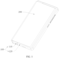
FIG. 1 is a schematic diagram of an electronic device in a contracted state according to this application; -
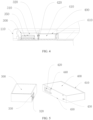
FIG. 2 is a partial exploded view of an electronic device in an expanded state according to this application; -
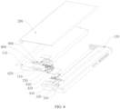
FIG. 3 is an exploded view of an electronic device in an expanded state according to this application; -
FIG. 4 is a partial sectional view of an electronic device according to this application; -
FIG. 5 is a schematic structural diagram of a sound generating module and a cavity according to this application; -
FIG. 6 is an exploded view of another embodiment of an electronic device according to this application; -
FIG. 7 is a partial exploded view of an electronic device according to this application; -
FIG. 8 is a partial exploded view of an electronic device according to this application; -
FIG. 9 is a schematic structural diagram of a first housing according to this application; -
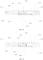
FIG. 10 is a sectional view along direction B-B inFIG. 9 of an electronic device in an expanded state according to this application; -
FIG. 11 is a sectional view along direction A-A inFIG. 9 of an electronic device in an expanded state according to this application; -
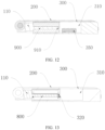
FIG. 12 is a sectional view along direction B-B inFIG. 9 of an electronic device in a contracted state according to this application; and -
FIG. 13 is a sectional view along direction A-A inFIG. 9 of an electronic device in a contracted state according to this application. -
- 100-device housing, 110-first housing portion, 120-second housing portion, 121-guiding protrusion;
- 200: flexible display;
- 300-sound generating module, 310-first rear cavity, 320-first connecting hole, 330-third positioning structure;
- 400-cavity, 410-second rear cavity, 420-second connecting hole, 430-first positioning structure, 440-second positioning structure, 450-guiding groove;
- 610-first elastic member, 620-second elastic member, 630-third elastic member;
- 710-first rear cavity component, 711-first chamfered surface, 720-second rear cavity component, 721-second chamfered surface;
- 800-functional component;
- 900-separating member, and 910-tip.
- To make the objectives, technical solutions, and advantages of this application clearer, the following clearly and completely describes the technical solutions of this application with reference to specific embodiments of this application and corresponding drawings. Apparently, the described embodiments are merely some but not all of the embodiments. All other embodiments obtained by persons of ordinary skill in the art based on the embodiments of this application without creative efforts shall fall within the protection scope of this application.
- The technical solutions disclosed in the embodiments of this application are described in detail below with reference to the accompanying drawings.
- As shown in
FIG. 1 to FIG. 13 , this application provides an electronic device including adevice housing 100 and asound generating module 300. - As a basic component of the electronic device, the
device housing 100 is capable of providing a mounting base for other components of the electronic device. Thedevice housing 100 includes afirst housing portion 110 and asecond housing portion 120. Thefirst housing portion 110 is movably disposed on thesecond housing portion 120 to enable the electronic device to switch between a first state and a second state. - One of the first state and the second state is an expanded state, and the other is a contracted state. In a case that the
first housing portion 110 and thesecond housing portion 120 are relatively far away from each other, the electronic device is in the expanded state, and in a case that they are relatively close to each other, the electronic device is in the contracted state. - The
sound generating module 300 may be a receiver module, a speaker module, or any other sound-generating apparatus. A specific type ofsound generating module 300 is not limited in the embodiments of this application. Thesound generating module 300 is provided on one of thefirst housing portion 110 and thesecond housing portion 120. - The
sound generating module 300 is provided with a firstrear cavity 310 and a first connectinghole 320 that communicates with the firstrear cavity 310. The electronic device is able to form a secondrear cavity 410. Specifically, in the first state, the firstrear cavity 310 communicates with the secondrear cavity 410 via the first connectinghole 320, and the firstrear cavity 310 and the secondrear cavity 410 that communicate with each other jointly form a rear cavity of thesound generating module 300. This increases the volume of the rear cavity of thesound generating module 300, thereby improving the sound performance of thesound generating module 300. In the second state, the first connectinghole 320 is blocked, and only the firstrear cavity 310 functions as the rear cavity of thesound generating module 300. - In the second state, the first connecting
hole 320 can be blocked by a dedicated blocking cover plate or by anotherfunctional component 800 of the electronic device. The blocking method can vary, and this embodiment of this application does not impose restrictions on this. - In the electronic device described in this application, the
sound generating module 300 is provided with a firstrear cavity 310, and the electronic device is further able to form a secondrear cavity 410, to fully utilize the internal space of the electronic device. In the expanded or contracted state of the electronic device, the firstrear cavity 310 communicates with the secondrear cavity 410, which in turn increases the volume of the rear cavity of thesound generating module 300 and improves sound performance, resulting in a more mellow and full sound. - In this embodiment of this application, the electronic device further includes a
flexible display 200, and theflexible display 200 is provided on thedevice housing 100. Specifically, a first end of theflexible display 200 is connected to thefirst housing portion 110, and a second end of theflexible display 200 is connected to thesecond housing portion 120. The first end of theflexible display 200 is capable of moving along with the movement of thefirst housing portion 110, and the second end of theflexible display 200 is capable of moving along with the movement of thesecond housing portion 120. In a case that thefirst housing portion 110 moves relative to thesecond housing portion 120, the first end of theflexible display 200 also moves relative to the second end of theflexible display 200, thereby changing a display area between the first end and the second end of theflexible display 200. In a case that the electronic device has a relatively large display area, it provides a better visual experience to user, and in a case that the electronic device has a relatively small display area, it is more convenient for portability. - The first end of the
flexible display 200 can be accommodated in thefirst housing portion 110 or can extend from thefirst housing portion 110, and/or the second end of theflexible display 200 can be accommodated in thesecond housing portion 120 or can extend from thesecond housing portion 120. There can be various manners for accommodation and extension, and this embodiment of this application does not impose restrictions on this. - Specifically, the
flexible display 200 is provided with a first region and a second region connected to the first region. - In the expanded state, the first region and the second region are at least partially exposed to the electronic device. In this case, the electronic device has a relatively large display area, and the first
rear cavity 310 is connected to the secondrear cavity 410 via the first connectinghole 320. The firstrear cavity 310 and the secondrear cavity 410 in communication jointly form the rear cavity of thesound generating module 300, fully utilizing the internal space of the electronic device. This increases the volume of the rear cavity of thesound generating module 300 and improves the sound performance of thesound generating module 300. - In the contracted state, the first region is exposed to the electronic device, and the second region is accommodated in the
device housing 100. In this case, the electronic device has a relatively small display area, and the first connectinghole 320 is blocked. - In this embodiment, in the expanded state, in the case that the electronic device has a relatively large display area, the large display area provides a better visual experience to user. In this case, the second
rear cavity 410 communicates with the firstrear cavity 310 to jointly form the rear cavity of thesound generating module 300, which in turn increases the volume of the rear cavity of thesound generating module 300 and improves the sound performance of thesound generating module 300, thus providing a better auditory experience to the user. - In the case that the electronic device has a relatively large display area, it can be used as a tablet, which requires higher sound performance. In this case, the second
rear cavity 410 communicates with the firstrear cavity 310 to jointly form the rear cavity of thesound generating module 300, which in turn increases the volume of the rear cavity of thesound generating module 300, improving the sound performance of thesound generating module 300, thereby meeting requirements for the sound performance of an electronic device with a relatively large display area. - In this embodiment of this application, the electronic device includes a
cavity structure 400. Thecavity structure 400 is provided with a secondrear cavity 410 and a second connectinghole 420 that communicates with the secondrear cavity 410, and thesound generating module 300 is provided with the firstrear cavity 310 and the first connectinghole 320 that communicates with the firstrear cavity 310. One of thesound generating module 300 and thecavity structure 400 is located on thefirst housing portion 110, and the other is located on thesecond housing portion 120. Thesound generating module 300 and thecavity structure 400 can relatively slide along with relative movement between thefirst housing portion 110 and thesecond housing portion 120. - In the first state, the first connecting
hole 320 and the second connectinghole 420 are in sealed alignment, and the firstrear cavity 310 communicates with the secondrear cavity 410 via the sealed alignment between the first connectinghole 320 and the second connectinghole 420. In this case, the secondrear cavity 410 communicates with the firstrear cavity 310 to jointly form the rear cavity of thesound generating module 300, so as to fully utilize the internal space of the electronic device. Communicating the secondrear cavity 410 and the firstrear cavity 310 increases the volume of the rear cavity of thesound generating module 300 and improves the sound performance of thesound generating module 300. - In the second state, the first connecting
hole 320 and the second connectinghole 420 are misaligned. Thecavity structure 400 blocks the first connectinghole 320. For example, in the second state, a side wall of thecavity structure 400 is precisely moved to align with the first connectinghole 320 to block the first connectinghole 320, and the firstrear cavity 310 functions as the rear cavity of thesound generating module 300 alone. - In this embodiment, in the first state, the second
rear cavity 410 of thecavity structure 400 can communicate with the firstrear cavity 310 via the second connectinghole 420, thereby increasing the volume of the rear cavity of thesound generating module 300; and in the second state, thecavity structure 400 blocks the first connectinghole 320 to seal the firstrear cavity 310, so that the firstrear cavity 310 functions as the rear cavity of thesound generating module 300 alone. - In the foregoing embodiment, one of the
sound generating module 300 and thecavity structure 400 is provided with afirst positioning structure 430 and asecond positioning structure 440 that are spaced apart, and the other is provided with athird positioning structure 330. In a case of the first state, thefirst positioning structure 430 and thethird positioning structure 330 cooperate with each other. After thefirst positioning structure 430 and thethird positioning structure 330 cooperate with each other, thesound generating module 300 and thecavity structure 400 are relatively fastened, so that the first connectinghole 320 and the second connectinghole 420 are aligned, thereby communicating the secondrear cavity 410 and the firstrear cavity 310. In a case of the second state, thesecond positioning structure 440 and thethird positioning structure 330 cooperate with each other. After thesecond positioning structure 440 and thethird positioning structure 330 cooperate with each other, thesound generating module 300 and thecavity structure 400 are relatively fastened, so that the first connectinghole 320 and thecavity structure 400 are aligned. For example, the first connectinghole 320 faces the side wall of thecavity structure 400, thecavity structure 400 blocks the first connecting hole of the firstrear cavity 310 to seal the firstrear cavity 310, so that the firstrear cavity 310 functions as the rear cavity of thesound generating module 300 alone. In a case that the firstrear cavity 310 communicates with the secondrear cavity 410 or that the first connectinghole 320 is blocked, the positioning structures can be used to position thesound generating module 300 and thecavity structure 400 to prevent relative sliding. - The positioning structures can take various forms, such as concave-convex positioning structures and magnetic positioning structures.
- In this embodiment of this application, concave-convex positioning structures are used as an example for description. Both the
first positioning structure 430 and thesecond positioning structure 440 are positioning protrusions, and thethird positioning structure 330 is a positioning groove. Alternatively, thefirst positioning structure 430 and thesecond positioning structure 440 are positioning grooves, and thethird positioning structure 330 is a positioning protrusion. In a case that thesound generating module 300 slides relative to thecavity structure 400 to a predetermined position, the positioning protrusion enters the positioning groove, achieving the positioning of thesound generating module 300 and thecavity structure 400. - The
sound generating module 300 is fixed on one of thefirst housing portion 110 and thesecond housing portion 120, and thecavity structure 400 is movably disposed in the other of thefirst housing portion 110 and thesecond housing portion 120. The electronic device further includes a firstelastic member 610. The firstelastic member 610 is connected between thecavity structure 400 and thefirst housing portion 110 or between thecavity structure 400 and thesecond housing portion 120. The firstelastic member 610 drives thecavity structure 400 to move towards thesound generating module 300. The firstelastic member 610 may be a leaf spring, a coil spring, a cushion, or other elastic members. - Disposing the first
elastic member 610 ensures a better fit between thecavity structure 400 and thesound generating module 300, so that the secondrear cavity 410 communicates with the firstrear cavity 310 in the first state, and thecavity structure 400 seals the first connectinghole 320 in the second state. The disposing of the firstelastic member 610 facilitates concave-convex positioning fit between the positioning structures. Due to the relative sliding between thecavity structure 400 and thesound generating module 300 during switching between the two states, the positioning protrusion needs to slide out of one positioning groove and then slide into another positioning groove. This requires thecavity structure 400 to have a given degree of movement in the convex direction of the protrusion, while disposing the firstelastic member 610 can enable thecavity structure 400 to have a given degree of movement in the convex direction of the protrusion. In the case that the positioning protrusion needs to slide out of the positioning groove, thecavity structure 400 compresses the firstelastic member 610, moving relatively away from thesound generating module 300 in the convex direction of the positioning protrusion. After the positioning protrusion slides into the positioning groove, the firstelastic member 610 compresses thecavity structure 400, driving thecavity structure 400 to move towards thesound generating module 300, ensuring a better fit between thecavity structure 400 and thesound generating module 300. - Further, in this embodiment, the
cavity structure 400 is provided with a guidingprotrusion 121, and one of thefirst housing portion 110 and thesecond housing portion 120 is provided with a guidinggroove 450, where the guidingprotrusion 121 matches with the guidinggroove 450. Alternatively, thecavity structure 400 is provided with a guidinggroove 450, and thefirst housing portion 110 or thesecond housing portion 120 is provided with a guidingprotrusion 121, where the guidingprotrusion 121 and the guidinggroove 450 are matched. Disposing the guidingprotrusion 121 and the guidinggroove 450 can better guide thecavity structure 400 to move a given distance relative to thesound generating module 300 in the convex direction of the positioning protrusion in a case that the positioning protrusion slides into or out of the positioning groove. Limiting fit between thecavity structure 400 and thefirst housing portion 110 or between thecavity structure 400 and thesecond housing portion 120 in the moving direction of thefirst housing portion 110 can ensure that thecavity structure 400 moves synchronously with one of thefirst housing portion 110 and thesecond housing portion 120 in a moving direction of thefirst housing portion 110, avoiding relative movement between thecavity structure 400 and thefirst housing portion 110 or between thecavity structure 400 and thesecond housing portion 120 in the moving direction of thefirst housing portion 110 caused by friction between thesound generating module 300 and thecavity structure 400. This ensures precise alignment between the first connectinghole 320 of the firstrear cavity 310 and the second connectinghole 420 of the secondrear cavity 410 each time thefirst housing portion 110 and thesecond housing portion 120 relatively move to the first state. - In this embodiment of this application, the electronic device includes a first
rear cavity component 710 and a secondrear cavity component 720. The firstrear cavity component 710, the secondrear cavity component 720, and thesound generating module 300 are all disposed on one of thefirst housing portion 110 and thesecond housing portion 120. The other of thefirst housing portion 110 and thesecond housing portion 120 is provided with afunctional component 800. For example, thefunctional component 800 can be a circuit board, a battery, or another functional component. - In this embodiment, in the expanded state, the second
rear cavity 410 is enclosed by at least the firstrear cavity component 710 and the secondrear cavity component 720. The secondrear cavity 410 can be enclosed solely by the firstrear cavity component 710 and the secondrear cavity component 720, or can be enclosed by a combination of the firstrear cavity component 710, the secondrear cavity component 720, and another structure. At least one of the firstrear cavity component 710 and the secondrear cavity component 720 has a second connectinghole 420 formed. Specifically, it can be that the firstrear cavity component 710 has the second connectinghole 420, or that the secondrear cavity component 720 has the second connectinghole 420, or that the firstrear cavity component 710 and the secondrear cavity component 720 each have a half-hole, and the two half-holes cooperate to form the second connectinghole 420. The second connectinghole 420 communicates with the secondrear cavity 410. The firstrear cavity 310 communicates with the secondrear cavity 410 via the sealed alignment of the first connectinghole 320 and the second connectinghole 420. The secondrear cavity 410 and the firstrear cavity 310 in communication j ointly form the rear cavity of thesound generating module 300, fully utilizing the internal space of the electronic device. Communicating the secondrear cavity 410 and the firstrear cavity 310 increases the volume of the rear cavity of thesound generating module 300 and improves the sound performance of thesound generating module 300. - In this embodiment, in the contracted state, the
functional component 800 moves to a position between the firstrear cavity component 710 and the secondrear cavity component 720, and thefunctional component 800 blocks the first connectinghole 320. The firstrear cavity component 710 and the secondrear cavity component 720 provide an installation space for thefunctional component 800, fully utilizing the space between the firstrear cavity component 710 and the secondrear cavity component 720 to arrange thefunctional component 800 in the electronic device. In addition, thefunctional component 800 can block the first connectinghole 320, further utilizing thefunctional component 800, allowing thefunctional component 800 to serve multiple purposes, not only performing own function of thefunctional component 800 but also blocking the first connectinghole 320. - In this embodiment, the space between the first
rear cavity component 710 and the secondrear cavity component 720 is a reused space. In the first state, the firstrear cavity component 710 and the secondrear cavity component 720 enclose the secondrear cavity 410. Communicating the secondrear cavity 410 and the firstrear cavity 310 increases the volume of the rear cavity of thesound generating module 300 and improves the sound performance of thesound generating module 300. In the second state, thefunctional component 800 can be accommodated between the firstrear cavity component 710 and the secondrear cavity component 720, fully utilizing the space between the firstrear cavity component 710 and the secondrear cavity component 720. In addition, thefunctional component 800 positioned between the firstrear cavity component 710 and the secondrear cavity component 720 can also block the first connectinghole 320. - Specifically, the first
rear cavity component 710 is movably arranged relative to the secondrear cavity component 720, and thefunctional component 800 is capable of moving along with one of thefirst housing portion 110 and thesecond housing portion 120. In the expanded state, the firstrear cavity component 710 moves to a position at which it aligns with the secondrear cavity component 720 to form the secondrear cavity 410, and thefunctional component 800 is located outside the secondrear cavity 410. The secondrear cavity 410 and the firstrear cavity 310 in communication jointly form the rear cavity of thesound generating module 300. Communicating the secondrear cavity 410 and the firstrear cavity 310 increases the volume of the rear cavity of thesound generating module 300 and improves the sound performance of thesound generating module 300. In the contracted state, thefunctional component 800 moves to the position between the firstrear cavity component 710 and the secondrear cavity component 720, thefunctional component 800 blocks the first connectinghole 320, and the firstrear cavity component 710 is separated from the secondrear cavity component 720. - In this embodiment of this application, the electronic device further includes a separating
member 900. The separatingmember 900 is fixed relative to thefunctional component 800 and is provided with atip 910. In the expanded state, the joint region of the firstrear cavity component 710 and the secondrear cavity component 720 is positioned facing thetip 910. In the contracted state, the separatingmember 900 is supported between the firstrear cavity component 710 and the secondrear cavity component 720. The separatingmember 900 can extend into the joint region of the firstrear cavity component 710 and the secondrear cavity component 720 via thetip 910, and then separate the firstrear cavity component 710 and the secondrear cavity component 720, so thefunctional component 800 can be accommodated in the space between the firstrear cavity component 710 and the secondrear cavity component 720. In this embodiment, the separatingmember 900 may alternatively be another functional component of the electronic device. - In this embodiment, the separating
member 900 is fixed relative to thefunctional component 800. The firstrear cavity component 710 is provided with a firstchamfered surface 711, and the secondrear cavity component 720 is provided with a secondchamfered surface 721. In the expanded state, the firstchamfered surface 711 and the secondchamfered surface 721 form a guiding space. An end portion or thetip 910 of the separatingmember 900 can extend into the guiding space formed by the firstchamfered surface 711 and the secondchamfered surface 721. A width of the guiding space decreases in a direction away from the separatingmember 900, where the width refers to a dimension of the guiding space in an alignment direction of the firstrear cavity component 710 and the secondrear cavity component 720. - In this embodiment, the first
rear cavity component 710 and the secondrear cavity component 720 can form acylindrical cavity structure 400. Thecylindrical cavity structure 400 is provided with holes at both ends, where the hole at the first end can be the second connectinghole 420, and the hole at the second end is for the extension of thefunctional component 800. Thefunctional component 800 can extend into the hole at the second end to enclose the secondrear cavity 410 together with the firstrear cavity component 710 and the secondrear cavity component 720. Thefunctional component 800 can further extend into the hole at the first end and block the first connectinghole 320. Thefunctional component 800 fits with thecylindrical cavity structure 400 functions in a manner similar to a piston and a piston rod. - The first
rear cavity component 710 and the secondrear cavity component 720 can be separated along with relative movement between thefirst housing portion 110 and thesecond housing portion 120. In this case, other components of the electronic device can be accommodated between the firstrear cavity component 710 and the secondrear cavity component 720. Alternatively, the firstrear cavity component 710 and the secondrear cavity component 720 can keeping abutting against each other without a structure to separate the firstrear cavity component 710 and the secondrear cavity component 720, thus simplifying the structure of the electronic device and facilitating the assembly. - In the foregoing embodiments, a second
elastic member 620 can be provided to drive the firstrear cavity component 710 to move. The secondelastic member 620 is provided between the firstrear cavity component 710 and thefirst housing portion 110 or between the firstrear cavity component 710 and thesecond housing portion 120. The secondelastic member 620 can drive the firstrear cavity component 710 to move towards the secondrear cavity component 720, so that the firstrear cavity component 710 abuts against the secondrear cavity component 720. The secondelastic member 620 may be a leaf spring, a coil spring, a cushion, or other elastic members. - Further, a third
elastic member 630 can be provided to drive the secondrear cavity component 720 to move. The thirdelastic member 630 is provided between the secondrear cavity component 720 and thefirst housing portion 110 or between the secondrear cavity component 720 and thesecond housing portion 120. The thirdelastic member 630 can drive the secondrear cavity component 720 to move towards the firstrear cavity component 710, so that the secondrear cavity component 720 abuts against the firstrear cavity component 710. The thirdelastic member 630 may be a leaf spring, a coil spring, a cushion, or other elastic members. - The above embodiments of this application focus on the differences between the embodiments. As long as different features of improvement in the embodiments are not contradictory, they can be combined to form a more preferred embodiment. Further descriptions are omitted herein for the purpose of brevity.
- The foregoing descriptions are merely embodiments of this application and are not intended to limit the application. For persons skilled in the art, this application may have various changes and variations. Any modifications, equivalent replacements, and improvements made without departing from the spirit and principle of this application shall fall within the protection scope of the claims of this application.
Claims (13)
- An electronic device comprising a device housing (100) and a sound generating module (300), wherein the device housing (100) comprises a first housing portion (110) and a second housing portion (120), the first housing portion (110) is movably disposed on the second housing portion (120) to enable the electronic device to switch between a first state and a second state, the sound generating module (300) is located on one of the first housing portion (110) and the second housing portion (120), and the sound generating module (300) is provided with a first rear cavity (310) and a first connecting hole (320) communicating with the first rear cavity (310), wherein the electronic device is able to form a second rear cavity (410), whereinin the first state, the first rear cavity (310) communicates with the second rear cavity (410) via the first connecting hole (320); in the second state, the first connecting hole (320) is blocked; andone of the first state and the second state is an expanded state, and the other is a contracted state.
- The electronic device according to claim 1, wherein the electronic device further comprises a flexible display (200), wherein a first end of the flexible display (200) is connected to the first housing portion (110), and a second end of the flexible display (200) is connected to the second housing portion (120), the flexible display (200) having a first region and a second region connected to the first region, whereinin the expanded state, the first region and the second region are at least partially exposed to the electronic device, and the first rear cavity (310) communicates with the second rear cavity (410) via the first connecting hole (320); andin the contracted state, the first region is exposed to the electronic device, the second region is accommodated within the device housing (100), and the first connecting hole (320) is blocked.
- The electronic device according to claim 1, wherein the electronic device comprises a cavity structure (400), and the cavity structure (400) is provided with the second rear cavity (410) and a second connecting hole (420) communicating with the second rear cavity (410);one of the sound generating module (300) and the cavity structure (400) is located on the first housing portion (110), and the other is located on the second housing portion (120), and the sound generating module (300) and the cavity structure (400) are capable of sliding relative to each other along with relative movement between the first housing portion (110) and the second housing portion (120), whereinin the first state, the first connecting hole (320) is in sealed alignment with the second connecting hole (420), and the first rear cavity (310) communicates with the second rear cavity (410) via the the first connecting hole (320) and the second connecting hole (420); andin the second state, the first connecting hole (320) is staggered with the second connecting hole (420), and the cavity structure (400) blocks the first connecting hole (320).
- The electronic device according to claim 3, wherein one of the sound generating module (300) and the cavity structure (400) is provided with a first positioning structure (430) and a second positioning structure (440) spaced apart, and the other is provided with a third positioning structure (330), whereinin the first state, the first positioning structure (430) cooperates with the third positioning structure (330); andin the second state, the second positioning structure (440) cooperates with the third positioning structure (330).
- The electronic device according to claim 4, wherein the first positioning structure (430) and the second positioning structure (440) are both positioning protrusions, and the third positioning structure (330) is a positioning groove, or the first positioning structure (430) and the second positioning structure (440) are both positioning grooves, and the third positioning structure (330) is a positioning protrusion.
- The electronic device according to claim 5, wherein the sound generating module (300) is fixed on one of the first housing portion (110) and the second housing portion (120), the cavity structure (400) is movably disposed in the other of the first housing portion (110) and the second housing portion (120), and the electronic device comprises a first elastic member (610), wherein the first elastic member (610) is connected between the cavity structure (400) and the first housing portion (110) or between the cavity structure (400) and the second housing portion (120), and the first elastic member (610) drives the cavity structure (400) to move towards the sound generating module (300).
- The electronic device according to claim 6, wherein the cavity structure (400) is provided with a guiding protrusion (121), and the first housing portion 110 or the second housing portion (120) is provided with a guiding groove (450), wherein the guiding protrusion (121) matches with the guiding groove (450); or the cavity structure (400) is provided with a guiding groove (450), and the first housing portion (110) or the second housing portion (120) is provided with a guiding protrusion, wherein the guiding protrusion (121) matches with the guiding groove (450), wherein
the cavity structure (400) is in limiting fit with the first housing portion (110) or the second housing portion (120) in a moving direction of the first housing portion (110). - The electronic device according to claim 1, wherein the electronic device comprises a first rear cavity component (710) and a second rear cavity component (720), wherein the first rear cavity component (710), the second rear cavity component (720), and the sound generating module (300) are all located on one of the first housing portion (110) and the second housing portion (120), and the other of the first housing portion (110) and the second housing portion (120) is provided with a functional component (800), whereinin the expanded state, the second rear cavity (410) is enclosed by at least the first rear cavity component (710) and the second rear cavity component (720), and at least one of the first rear cavity component (710) and the second rear cavity component (720) is formed with a second connecting hole (420), wherein the second connecting hole (420) communicates with the second rear cavity (410), and the first rear cavity (310) communicates with the second rear cavity (410) via the sealed alignment of the first connecting hole (320) and the second connecting hole (420); andin the contracted state, the functional component (800) moves to a position between the first rear cavity component (710) and the second rear cavity component (720), and the functional component (800) blocks the first connecting hole (320).
- The electronic device according to claim 8, wherein the first rear cavity component (710) is movably disposed relative to the second rear cavity component (720), and the functional component (800) is capable of moving with the first housing portion (110) or the second housing portion (120), whereinin the expanded state, the first rear cavity component (710) moves to a position at which it aligns with the second rear cavity component (720) to form the second rear cavity (410), and the functional component (800) is located outside the second rear cavity (410); andin the contracted state, the functional component (800) moves to a position between the first rear cavity component 710 and the second rear cavity component (720), the functional component (800) blocks the first connecting hole (320), and the first rear cavity component (710) is separated from the second rear cavity component (720).
- The electronic device according to claim 9, wherein the electronic device further comprises a separating member (900), wherein the separating member (900) is fixed relative to the functional component (800), and the separating member (900) has a tip (910), wherein in the expanded state, the joint region of the first rear cavity component (710) and the second rear cavity component (720) is disposed facing the tip (910), and in the contracted state, the separating member (900) supports between the first rear cavity component (710) and the second rear cavity component (720).
- The electronic device according to claim 9, wherein the electronic device further comprises a separating member (900), wherein the separating member (900) is fixed relative to the functional component (800), the first rear cavity component (710) is provided with a first chamfered surface (711), and the second rear cavity component (720) is provided with a second chamfered surface (721), wherein in the expanded state, the first chamfered surface (711) and the second chamfered surface (721) form a guiding space, and width of the guiding space decreases in a direction away from the separating member (900), wherein the width is a dimension of the guiding space in an alignment direction of the first rear cavity component (710) and the second rear cavity component (720).
- The electronic device according to claim 9, wherein a second elastic member (620) is provided between the first rear cavity component (710) and the first housing portion (110) or between the first rear cavity component (710) and the second housing portion (120), and the second elastic member (620) is capable of driving the first rear cavity component (710) to move towards the second rear cavity component (720) so that the first rear cavity component (710) abuts against the second rear cavity component (720).
- The electronic device according to claim 12, wherein a third elastic member (630) is provided between the second rear cavity component (720) and the first housing portion (110) or between the second rear cavity component (720) the second housing portion (120), and the third elastic member (630) is capable of driving the second rear cavity component (720) to move towards the first rear cavity component (710) so that the second rear cavity component (720) abuts against the first rear cavity component 710.
Applications Claiming Priority (2)
| Application Number | Priority Date | Filing Date | Title |
|---|---|---|---|
| CN202110451686.6A CN113099014B (en) | 2021-04-26 | 2021-04-26 | Electronic device |
| PCT/CN2022/088087 WO2022228258A1 (en) | 2021-04-26 | 2022-04-21 | Electronic device |
Publications (1)
| Publication Number | Publication Date |
|---|---|
| EP4333409A1 true EP4333409A1 (en) | 2024-03-06 |
Family
ID=76679893
Family Applications (1)
| Application Number | Title | Priority Date | Filing Date |
|---|---|---|---|
| EP22794729.8A Pending EP4333409A1 (en) | 2021-04-26 | 2022-04-21 | Electronic device |
Country Status (5)
| Country | Link |
|---|---|
| US (1) | US20240056518A1 (en) |
| EP (1) | EP4333409A1 (en) |
| JP (1) | JP2024514970A (en) |
| CN (1) | CN113099014B (en) |
| WO (1) | WO2022228258A1 (en) |
Families Citing this family (2)
| Publication number | Priority date | Publication date | Assignee | Title |
|---|---|---|---|---|
| CN112769989B (en) * | 2021-01-05 | 2023-04-28 | 深圳市锐尔觅移动通信有限公司 | Sound generating device and electronic equipment |
| CN113099014B (en) * | 2021-04-26 | 2023-03-21 | 维沃移动通信有限公司 | Electronic device |
Family Cites Families (19)
| Publication number | Priority date | Publication date | Assignee | Title |
|---|---|---|---|---|
| US8213659B2 (en) * | 2009-06-30 | 2012-07-03 | Nokia Corporation | Apparatus with adjustable speaker arrangement |
| CN202818539U (en) * | 2012-09-29 | 2013-03-20 | 广州三星通信技术研究有限公司 | Stretched type sound box for portable terminal |
| US9386134B2 (en) * | 2013-10-22 | 2016-07-05 | Nokia Corporation | Speaker back cavity |
| US9807483B1 (en) * | 2016-12-07 | 2017-10-31 | BassCase LLC | Mobile device case with foldable speaker system |
| CN110714976A (en) * | 2018-07-13 | 2020-01-21 | Oppo广东移动通信有限公司 | Folding electronic device and control method thereof |
| CN109324780B (en) * | 2018-09-27 | 2021-01-15 | 联想(北京)有限公司 | Method for improving sound output effect and electronic equipment |
| CN109769052B (en) * | 2019-03-06 | 2020-09-08 | Oppo广东移动通信有限公司 | Electronic device |
| CN211127868U (en) * | 2020-03-23 | 2020-07-28 | 西安易朴通讯技术有限公司 | Mobile terminal |
| CN111526453B (en) * | 2020-04-26 | 2022-01-07 | 维沃移动通信有限公司 | Electronic device |
| CN111770221B (en) * | 2020-07-07 | 2021-07-16 | 维沃移动通信有限公司 | Electronic device |
| CN212519077U (en) * | 2020-08-28 | 2021-02-09 | 维沃移动通信有限公司 | Electronic device |
| CN112055107B (en) * | 2020-09-09 | 2022-05-10 | 维沃移动通信有限公司 | Electronic device |
| CN112291399B (en) * | 2020-10-28 | 2022-08-12 | 维沃移动通信有限公司 | Sound production module, electronic equipment, control method and control device of electronic equipment |
| CN112291397B (en) * | 2020-10-30 | 2023-05-23 | 维沃移动通信有限公司 | Electronic device, control method and control device thereof, and readable storage medium |
| CN112398986A (en) * | 2020-11-16 | 2021-02-23 | Oppo广东移动通信有限公司 | Electronic device |
| CN112600963B (en) * | 2020-12-11 | 2023-03-21 | 维沃移动通信有限公司 | Electronic equipment |
| CN112615950B (en) * | 2020-12-18 | 2023-06-30 | 维沃移动通信有限公司 | Electronic equipment |
| CN113114818B (en) * | 2021-04-16 | 2024-01-05 | 维沃移动通信有限公司 | Electronic equipment |
| CN113099014B (en) * | 2021-04-26 | 2023-03-21 | 维沃移动通信有限公司 | Electronic device |
-
2021
- 2021-04-26 CN CN202110451686.6A patent/CN113099014B/en active Active
-
2022
- 2022-04-21 EP EP22794729.8A patent/EP4333409A1/en active Pending
- 2022-04-21 JP JP2023565415A patent/JP2024514970A/en active Pending
- 2022-04-21 WO PCT/CN2022/088087 patent/WO2022228258A1/en active Application Filing
-
2023
- 2023-10-24 US US18/492,847 patent/US20240056518A1/en active Pending
Also Published As
| Publication number | Publication date |
|---|---|
| CN113099014A (en) | 2021-07-09 |
| CN113099014B (en) | 2023-03-21 |
| JP2024514970A (en) | 2024-04-03 |
| US20240056518A1 (en) | 2024-02-15 |
| WO2022228258A1 (en) | 2022-11-03 |
Similar Documents
| Publication | Publication Date | Title |
|---|---|---|
| US20240056518A1 (en) | Electronic device | |
| US7630744B2 (en) | Slide type mobile terminal and sliding mechanism thereof | |
| CN109803071B (en) | Camera assembly and mobile terminal | |
| KR100396518B1 (en) | One key data inputting device and portable telephone therewith | |
| EP1545099B1 (en) | Method and system for a slide type portable terminal | |
| US20170055064A1 (en) | Sound output apparatus | |
| EP4117255A1 (en) | Electronic device | |
| CN100508705C (en) | Slide module for portable terminal and cover device of external card mounted on it | |
| CN112995469A (en) | Imaging device and electronic apparatus | |
| US10062985B2 (en) | Connector module and portable electronic device | |
| CN113936944B (en) | Electronic equipment | |
| CN108418917B (en) | Electronic component and electronic device | |
| CN113259515B (en) | Electronic equipment | |
| KR102258860B1 (en) | Voice coil motor, assembly method of voice coil motor, and camera module having the same | |
| CN114793258B (en) | Camera module and terminal equipment | |
| CN210469392U (en) | Electronic device | |
| KR20020088214A (en) | Wireless Mobile Phone with Slide Module | |
| EP4191313A1 (en) | Ultrasonic piezoelectric motor, camera module, and electronic device | |
| CN114338991B (en) | Magnetic positioning mechanism, camera mechanism and electronic equipment | |
| CN218603515U (en) | Protective shell | |
| CN219609528U (en) | Shielding structure of camera, camera assembly and computer | |
| KR200244598Y1 (en) | Wireless Mobile Phone with Slide Module | |
| KR20210063314A (en) | Voice coil motor, assembly method of voice coil motor, and camera module having the same | |
| CN115527789A (en) | Side key structure and electronic equipment | |
| CN116567119A (en) | Electronic equipment |
Legal Events
| Date | Code | Title | Description |
|---|---|---|---|
| STAA | Information on the status of an ep patent application or granted ep patent |
Free format text: STATUS: THE INTERNATIONAL PUBLICATION HAS BEEN MADE |
|
| PUAI | Public reference made under article 153(3) epc to a published international application that has entered the european phase |
Free format text: ORIGINAL CODE: 0009012 |
|
| STAA | Information on the status of an ep patent application or granted ep patent |
Free format text: STATUS: REQUEST FOR EXAMINATION WAS MADE |
|
| 17P | Request for examination filed |
Effective date: 20231019 |
|
| AK | Designated contracting states |
Kind code of ref document: A1 Designated state(s): AL AT BE BG CH CY CZ DE DK EE ES FI FR GB GR HR HU IE IS IT LI LT LU LV MC MK MT NL NO PL PT RO RS SE SI SK SM TR |