EP4332486A1 - Wärmetauscher und verfahren zu dessen herstellung - Google Patents
Wärmetauscher und verfahren zu dessen herstellung Download PDFInfo
- Publication number
- EP4332486A1 EP4332486A1 EP23195078.3A EP23195078A EP4332486A1 EP 4332486 A1 EP4332486 A1 EP 4332486A1 EP 23195078 A EP23195078 A EP 23195078A EP 4332486 A1 EP4332486 A1 EP 4332486A1
- Authority
- EP
- European Patent Office
- Prior art keywords
- heat exchanger
- core
- coil
- coil tube
- liquid
- Prior art date
- Legal status (The legal status is an assumption and is not a legal conclusion. Google has not performed a legal analysis and makes no representation as to the accuracy of the status listed.)
- Granted
Links
Images

Classifications
-
- F—MECHANICAL ENGINEERING; LIGHTING; HEATING; WEAPONS; BLASTING
- F28—HEAT EXCHANGE IN GENERAL
- F28D—HEAT-EXCHANGE APPARATUS, NOT PROVIDED FOR IN ANOTHER SUBCLASS, IN WHICH THE HEAT-EXCHANGE MEDIA DO NOT COME INTO DIRECT CONTACT
- F28D7/00—Heat-exchange apparatus having stationary tubular conduit assemblies for both heat-exchange media, the media being in contact with different sides of a conduit wall
- F28D7/02—Heat-exchange apparatus having stationary tubular conduit assemblies for both heat-exchange media, the media being in contact with different sides of a conduit wall the conduits being helically coiled
-
- F—MECHANICAL ENGINEERING; LIGHTING; HEATING; WEAPONS; BLASTING
- F28—HEAT EXCHANGE IN GENERAL
- F28D—HEAT-EXCHANGE APPARATUS, NOT PROVIDED FOR IN ANOTHER SUBCLASS, IN WHICH THE HEAT-EXCHANGE MEDIA DO NOT COME INTO DIRECT CONTACT
- F28D1/00—Heat-exchange apparatus having stationary conduit assemblies for one heat-exchange medium only, the media being in contact with different sides of the conduit wall, in which the other heat-exchange medium is a large body of fluid, e.g. domestic or motor car radiators
- F28D1/02—Heat-exchange apparatus having stationary conduit assemblies for one heat-exchange medium only, the media being in contact with different sides of the conduit wall, in which the other heat-exchange medium is a large body of fluid, e.g. domestic or motor car radiators with heat-exchange conduits immersed in the body of fluid
- F28D1/0206—Heat exchangers immersed in a large body of liquid
- F28D1/022—Heat exchangers immersed in a large body of liquid for immersion in a natural body of water, e.g. marine radiators
-
- F—MECHANICAL ENGINEERING; LIGHTING; HEATING; WEAPONS; BLASTING
- F28—HEAT EXCHANGE IN GENERAL
- F28D—HEAT-EXCHANGE APPARATUS, NOT PROVIDED FOR IN ANOTHER SUBCLASS, IN WHICH THE HEAT-EXCHANGE MEDIA DO NOT COME INTO DIRECT CONTACT
- F28D1/00—Heat-exchange apparatus having stationary conduit assemblies for one heat-exchange medium only, the media being in contact with different sides of the conduit wall, in which the other heat-exchange medium is a large body of fluid, e.g. domestic or motor car radiators
- F28D1/02—Heat-exchange apparatus having stationary conduit assemblies for one heat-exchange medium only, the media being in contact with different sides of the conduit wall, in which the other heat-exchange medium is a large body of fluid, e.g. domestic or motor car radiators with heat-exchange conduits immersed in the body of fluid
- F28D1/04—Heat-exchange apparatus having stationary conduit assemblies for one heat-exchange medium only, the media being in contact with different sides of the conduit wall, in which the other heat-exchange medium is a large body of fluid, e.g. domestic or motor car radiators with heat-exchange conduits immersed in the body of fluid with tubular conduits
- F28D1/047—Heat-exchange apparatus having stationary conduit assemblies for one heat-exchange medium only, the media being in contact with different sides of the conduit wall, in which the other heat-exchange medium is a large body of fluid, e.g. domestic or motor car radiators with heat-exchange conduits immersed in the body of fluid with tubular conduits the conduits being bent, e.g. in a serpentine or zig-zag
-
- F—MECHANICAL ENGINEERING; LIGHTING; HEATING; WEAPONS; BLASTING
- F28—HEAT EXCHANGE IN GENERAL
- F28D—HEAT-EXCHANGE APPARATUS, NOT PROVIDED FOR IN ANOTHER SUBCLASS, IN WHICH THE HEAT-EXCHANGE MEDIA DO NOT COME INTO DIRECT CONTACT
- F28D21/00—Heat-exchange apparatus not covered by any of the groups F28D1/00 - F28D20/00
- F28D21/0001—Recuperative heat exchangers
- F28D21/0012—Recuperative heat exchangers the heat being recuperated from waste water or from condensates
-
- F—MECHANICAL ENGINEERING; LIGHTING; HEATING; WEAPONS; BLASTING
- F28—HEAT EXCHANGE IN GENERAL
- F28D—HEAT-EXCHANGE APPARATUS, NOT PROVIDED FOR IN ANOTHER SUBCLASS, IN WHICH THE HEAT-EXCHANGE MEDIA DO NOT COME INTO DIRECT CONTACT
- F28D21/00—Heat-exchange apparatus not covered by any of the groups F28D1/00 - F28D20/00
- F28D21/0017—Flooded core heat exchangers
-
- F—MECHANICAL ENGINEERING; LIGHTING; HEATING; WEAPONS; BLASTING
- F28—HEAT EXCHANGE IN GENERAL
- F28D—HEAT-EXCHANGE APPARATUS, NOT PROVIDED FOR IN ANOTHER SUBCLASS, IN WHICH THE HEAT-EXCHANGE MEDIA DO NOT COME INTO DIRECT CONTACT
- F28D7/00—Heat-exchange apparatus having stationary tubular conduit assemblies for both heat-exchange media, the media being in contact with different sides of a conduit wall
- F28D7/02—Heat-exchange apparatus having stationary tubular conduit assemblies for both heat-exchange media, the media being in contact with different sides of a conduit wall the conduits being helically coiled
- F28D7/024—Heat-exchange apparatus having stationary tubular conduit assemblies for both heat-exchange media, the media being in contact with different sides of a conduit wall the conduits being helically coiled the conduits of only one medium being helically coiled tubes, the coils having a cylindrical configuration
-
- F—MECHANICAL ENGINEERING; LIGHTING; HEATING; WEAPONS; BLASTING
- F28—HEAT EXCHANGE IN GENERAL
- F28D—HEAT-EXCHANGE APPARATUS, NOT PROVIDED FOR IN ANOTHER SUBCLASS, IN WHICH THE HEAT-EXCHANGE MEDIA DO NOT COME INTO DIRECT CONTACT
- F28D7/00—Heat-exchange apparatus having stationary tubular conduit assemblies for both heat-exchange media, the media being in contact with different sides of a conduit wall
- F28D7/02—Heat-exchange apparatus having stationary tubular conduit assemblies for both heat-exchange media, the media being in contact with different sides of a conduit wall the conduits being helically coiled
- F28D7/028—Heat-exchange apparatus having stationary tubular conduit assemblies for both heat-exchange media, the media being in contact with different sides of a conduit wall the conduits being helically coiled the conduits of at least one medium being helically coiled, the coils having a conical configuration
-
- F—MECHANICAL ENGINEERING; LIGHTING; HEATING; WEAPONS; BLASTING
- F28—HEAT EXCHANGE IN GENERAL
- F28D—HEAT-EXCHANGE APPARATUS, NOT PROVIDED FOR IN ANOTHER SUBCLASS, IN WHICH THE HEAT-EXCHANGE MEDIA DO NOT COME INTO DIRECT CONTACT
- F28D7/00—Heat-exchange apparatus having stationary tubular conduit assemblies for both heat-exchange media, the media being in contact with different sides of a conduit wall
- F28D7/04—Heat-exchange apparatus having stationary tubular conduit assemblies for both heat-exchange media, the media being in contact with different sides of a conduit wall the conduits being spirally coiled
-
- F—MECHANICAL ENGINEERING; LIGHTING; HEATING; WEAPONS; BLASTING
- F28—HEAT EXCHANGE IN GENERAL
- F28F—DETAILS OF HEAT-EXCHANGE AND HEAT-TRANSFER APPARATUS, OF GENERAL APPLICATION
- F28F21/00—Constructions of heat-exchange apparatus characterised by the selection of particular materials
- F28F21/06—Constructions of heat-exchange apparatus characterised by the selection of particular materials of plastics material
- F28F21/062—Constructions of heat-exchange apparatus characterised by the selection of particular materials of plastics material the heat-exchange apparatus employing tubular conduits
-
- F—MECHANICAL ENGINEERING; LIGHTING; HEATING; WEAPONS; BLASTING
- F28—HEAT EXCHANGE IN GENERAL
- F28F—DETAILS OF HEAT-EXCHANGE AND HEAT-TRANSFER APPARATUS, OF GENERAL APPLICATION
- F28F9/00—Casings; Header boxes; Auxiliary supports for elements; Auxiliary members within casings
-
- F—MECHANICAL ENGINEERING; LIGHTING; HEATING; WEAPONS; BLASTING
- F28—HEAT EXCHANGE IN GENERAL
- F28F—DETAILS OF HEAT-EXCHANGE AND HEAT-TRANSFER APPARATUS, OF GENERAL APPLICATION
- F28F9/00—Casings; Header boxes; Auxiliary supports for elements; Auxiliary members within casings
- F28F9/22—Arrangements for directing heat-exchange media into successive compartments, e.g. arrangements of guide plates
-
- F—MECHANICAL ENGINEERING; LIGHTING; HEATING; WEAPONS; BLASTING
- F25—REFRIGERATION OR COOLING; COMBINED HEATING AND REFRIGERATION SYSTEMS; HEAT PUMP SYSTEMS; MANUFACTURE OR STORAGE OF ICE; LIQUEFACTION SOLIDIFICATION OF GASES
- F25B—REFRIGERATION MACHINES, PLANTS OR SYSTEMS; COMBINED HEATING AND REFRIGERATION SYSTEMS; HEAT PUMP SYSTEMS
- F25B2339/00—Details of evaporators; Details of condensers
- F25B2339/02—Details of evaporators
- F25B2339/024—Evaporators with refrigerant in a vessel in which is situated a heat exchanger
- F25B2339/0242—Evaporators with refrigerant in a vessel in which is situated a heat exchanger having tubular elements
-
- F—MECHANICAL ENGINEERING; LIGHTING; HEATING; WEAPONS; BLASTING
- F25—REFRIGERATION OR COOLING; COMBINED HEATING AND REFRIGERATION SYSTEMS; HEAT PUMP SYSTEMS; MANUFACTURE OR STORAGE OF ICE; LIQUEFACTION SOLIDIFICATION OF GASES
- F25B—REFRIGERATION MACHINES, PLANTS OR SYSTEMS; COMBINED HEATING AND REFRIGERATION SYSTEMS; HEAT PUMP SYSTEMS
- F25B2339/00—Details of evaporators; Details of condensers
- F25B2339/04—Details of condensers
- F25B2339/046—Condensers with refrigerant heat exchange tubes positioned inside or around a vessel containing water or pcm to cool the refrigerant gas
-
- F—MECHANICAL ENGINEERING; LIGHTING; HEATING; WEAPONS; BLASTING
- F25—REFRIGERATION OR COOLING; COMBINED HEATING AND REFRIGERATION SYSTEMS; HEAT PUMP SYSTEMS; MANUFACTURE OR STORAGE OF ICE; LIQUEFACTION SOLIDIFICATION OF GASES
- F25B—REFRIGERATION MACHINES, PLANTS OR SYSTEMS; COMBINED HEATING AND REFRIGERATION SYSTEMS; HEAT PUMP SYSTEMS
- F25B2339/00—Details of evaporators; Details of condensers
- F25B2339/04—Details of condensers
- F25B2339/047—Water-cooled condensers
-
- F—MECHANICAL ENGINEERING; LIGHTING; HEATING; WEAPONS; BLASTING
- F25—REFRIGERATION OR COOLING; COMBINED HEATING AND REFRIGERATION SYSTEMS; HEAT PUMP SYSTEMS; MANUFACTURE OR STORAGE OF ICE; LIQUEFACTION SOLIDIFICATION OF GASES
- F25B—REFRIGERATION MACHINES, PLANTS OR SYSTEMS; COMBINED HEATING AND REFRIGERATION SYSTEMS; HEAT PUMP SYSTEMS
- F25B39/00—Evaporators; Condensers
- F25B39/02—Evaporators
-
- F—MECHANICAL ENGINEERING; LIGHTING; HEATING; WEAPONS; BLASTING
- F25—REFRIGERATION OR COOLING; COMBINED HEATING AND REFRIGERATION SYSTEMS; HEAT PUMP SYSTEMS; MANUFACTURE OR STORAGE OF ICE; LIQUEFACTION SOLIDIFICATION OF GASES
- F25B—REFRIGERATION MACHINES, PLANTS OR SYSTEMS; COMBINED HEATING AND REFRIGERATION SYSTEMS; HEAT PUMP SYSTEMS
- F25B39/00—Evaporators; Condensers
- F25B39/04—Condensers
Definitions
- the invention relates to heat exchangers, especially to heat exchangers for recovering and releasing heat from water.
- the invention relates to heat exchangers for recovering heat from water in low temperatures.
- heat exchangers for low temperatures can be found in EP 3117170 , SE 165824 , SU 785633 , US 4735261 and WO 2012064387 .
- a heat exchanger comprising a cylindrical core, a heat exchanger tubing for a first liquid, a body surrounding the heat exchanger tubing, wherein the inner surface of the body has the same shape as the outer borderline of the heat exchanger tubing.
- the heat exchanger tubing has a first part formed as a cone having first diameter and a second larger diameter, and a second part formed as a cylinder having the same diameter as the second larger diameter of the cone wherein the inner surface of the body forms a shell around the heat exchanger tubing and delineates with the core a flow path for a second liquid.
- a method for producing heat exchanger comprising:
- a heat exchanger wherein all major parts are made of plastic, at least the parts forming and within the flow path of the second liquid.
- a heat exchanger wherein the heat exchanger tubing comprises a first coil tube coiled around the core and at least one second coil tube coiled around the first coil tube wherein the first end of the first coil tube is located at vicinity of the first end of the core and the first end of the second coil tube is located at a distance from the first end of the core that is greater than the distance between the first end of the first coil tube and the first end of the core so that the first ends of the coil tubes form a cone at the first end of the core and the second ends of the coil tubes are set on a same plane.
- the heat exchanger tubing comprises multiple successive coil tubes having first ends distanced gradually at longer distances from the first end of the core.
- each coil tube is the same.
- a heat exchanger comprising at least one axial divider wall extending between the outer surface of the core and the inner surface of the body and having holes for coil tubes.
- a heat exchanger comprising at least one radial divider extending from either the outer surface of the core or the inner surface of the body in between the coil tubes creating one or multiple flow paths for the second liquid.
- the ninth aspect of the invention there is provided a heat exchanger wherein the axial dividers comprise multiple holes.
- a heat exchanger wherein the coil tubes (6, 7, 7xx) are single continuous pipes without splices or joints.
- the heat exchanger described herein is primarily for collecting heat energy or for dissipating heat energy for cooling using sea- river or lake water or other water bodies having sufficient volume.
- the heat exchanger is usable in waters at low temperatures, even close to the freezing temperature.
- the heat exchanger is suitable for connecting to a heat pump system for either collecting heat to a heat pump circuit or for dissipating heat from the circuit.
- the heat exchanger has a flow path for the liquid from which the heat is collected or dissipated to formed so that the cross section of the flow path decreases in the flow direction, i.e. the direction on which the temperature of the second liquid decreases.
- a coil tube assembly for the first liquid is fitted in the flow path of the secondary liquid.
- the heat exchanger is preferably made of plastic, for example polyethylene or polypropylene.
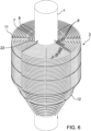
- FIGURE 1 illustrates a heat exchanger in accordance with at least some embodiments of the present invention.
- a heat exchanger tubing 2 is arranged around the core 1 and the heat exchanger tubing 2 is forms an outer borderline defining the shape of the heat exchanger tubing 2.
- the shape of the heat exchanger tubing 2 has a first part 4 formed as a cone and a second part 5 formed as a cylinder.
- the diameter of the cylinder is the same as the largest diameter of the cone, so these diameters match each other.
- a body 3 forms the outer casing of the heat exchanger.
- the outer surface of the body is cylindrical.
- the inner surface of the body is also cylindrical, but has a lining wall 13 extending from the inner surface of the cylinder towards the core 1.
- the lining wall 13 forms a cone funnel over the heat exchanger tubing 2 and the inner shape of the lining wall 13 follows the outer border line of the heat exchanger tubing at a distance, placing the inner wall of the body 3 parallel at a distance from the outer borderline of the heat exchanger tubing 2.
- the inner wall of the body 3 with the lining wall 13 and the outer surface of the core 1 form a flow path for a liquid.
- This liquid is the second liquid, that functions as a volume from which the heat is collected from or to which it is dissipated.
- the second liquid is usually water, as it is easily accessible in large enough volumes. However, any other liquid may be used, as long as the materials and structure of the heat exchanger is capable of handling such liquid, e.g. waste water, process water.
- the second liquid is fed to the heat exchanger through an intake 14 that is placed over the top of the heat exchanger tubing 2 when the heat exchanger is in vertical position in relation to the ground, i.e. the central axis of the core and the heat exchanger being placed on a right angle in relation to the ground. From the intake 14 the second liquid flows on a screen 15.
- the screen 15 is a plate having holes in it. This simple part effectively divides the second liquid over the heat exchanger tubing placed under it.
- the second liquid flows by the gravity downwards over the heat exchanger tubing and releases heat to the first liquid flowing in the heat exchanger tubing 2. Consequently the temperature of the second liquid decreases.
- the action is obviously the opposite.
- the heat exchanger may be used even in cold waters having temperature only few degrees above zero, even at a range from 0,5 - 5°C, freezing may be a problem.
- the second liquid flows on the bottom reservoir 16 of the body 3 and exits via outlet 17.
- the operation and setup of the heat exchanger is described herein in a vertical mounting and operation position.
- the apparatus may be operated and mounted horizontally, for example, or on an angle to the ground. If such mounting positions are used, forced feeding of second liquid may be needed. This applies to all assemblies when sufficient flow speed can't be achieved by gravity.
- the force feeding may be accomplished by pumping or using a liquid source placed on an elevated position in relation to the heat exchanger.
- the first liquid i.e. the liquid used for collecting or dissipating the heat energy
- the manifold 18 is connected to first ends 9 of each of the coil tubes 6, 7, 7xx of the heat exchanger tubing 2.
- the feed pipe 19 of the manifold 18 runs from the manifold 18 through the core to the top of the heat exchanger and therefrom to other parts of the heating/cooling system.
- the second ends 10 of the coil tubes 6, 7, 7xx are connected through a collector 20 to an exit pipe 21.
- the exit pipe also runs through the core 1.
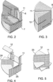
- the structure of the heat exchange tubing 2 is described in the following referring to FIGURES 2-6 .
- the core has axial brackets 22. herein 4, but other number might be used.
- On these brackets 22 are mounted axial divider walls 11. These axial divider walls 11?? divide the circumference of the heat exchanger tubing in sections, in this case quadrants.
- the coil tubes 6, 7, 7xx are mounted on these axial divider walls 11?.
- Each axial divider wall 11 is built of mounting strips 23.
- the mounting strips 23 have semi-circular seats 24 for a coil tube and fasteners for joining the mounting strips to the brackets and to each other.
- the seats may have other forms, for example oval or angular.
- the seat doesn't adapt closely to the outer cross section of the coil tube, the seats allow passage of water between eh mounting strip and the coil tube.
- the fasteners may be of any convenient kind, for example snap-on clips, rivets, screws, or glue. However, metal parts should be avoided in order to prevent risk of freezing and corrosion.
- the first mounting strips 23 (4 pcs) are fixed on the brackets of the core 1 and the first coil tube 6 is wound around the core 1 placing the coil tube in the seats 24 of the mounting strips 23.
- the first end 9 of the first coil tube is placed closest to the first end 8 of the core 1, i.e. closest to the bottom of the heat exchanger.
- the first coil tube 6 is would around the core until the top wherein the second end of the coil tube 10 is set on a set level.
- next mounting strip 23 may be attached to the previous one locking the first coil tube 6 on its place.
- the second coil tube 7 is would on the mounting strip 23, but now the first end 9 of the second coil tube 7 is set further away from the bottom of the heat exchanger.
- the second end 10 of the second coil tube 7 is set on the same level as the first coil tube 6.
- Further coil tubes 7xx are mounted in similar fashion by adding mounting strips and successive coil tubes.
- the first purpose of this structure is to form said cone shape to accommodate the conical shape of the inner wall of the body.
- the second purpose is to enable using coil tubes having same length.
- the first ends of the coil tubes are connected to a manifold 18 (18?) and the second ends to a collector 20.
- the second ends of the coil tubes are set on a same level.
- radial dividers 12 are set between the rounds of coil tubes.
- the radial dividers 12 are perforated plates mounted on axial divider walls 11. by trusses 25.
- the radial dividers 12 are set stepwise over the axial length of the heat exchanger tubing so that every other radial divider plate extends from the outer surface of the core 1 and every other from the inner wall of the body 3.
- Each of the radial divider plates extend only partially over the radial distance between the inner wall of the body and the outer surface of the body creating stepwise winding flow path. In this way the second liquid is mixed and its temperature is evened out.
- One feature relates to perforations of the radial dividers 12. The perforations allow second liquid to flow over the coil tube under the radial divider 12 so that the surface of the coil tube is not obscured by the axial divider plate.
- the apparatus described above and depicted in the drawings is configured by using parts that have circular cross section.
- Such parts like core, body and connecting pipelines can be conveniently obtained as they are or can be manufactured by using existing apparatuses of plastic industry.
- the core and body are made of parts having oval cross section.
- Such configuration may be needed to fit the heat exchanger in shallow heat sources. Any sharply angular cross sections like rectangular or hexagonal are to be avoided as they may create areas where flow speed is decreased, leading to decreased heat transfer and affinity to freezing.
- the preferred material of the heat exchanger is plastic, in particular polyethylene (PE), polypropylene (PP).
- PE polyethylene
- PP polypropylene
- the bottom of the heat exchanger can be made of a panel made of plastic profiles, e.g. UPONOR WEHOPANEL ® for example.
- the body may be made of tube made of wound profile.
- the second liquid is, for example ethanol. This allows for incoming temperatures of the first liquid as low as 0,5 - 1°C.
- the size of the heat exchanger dimensions of 2,4 m diameter, up to 3 - 4 m high, comprising 13 rounds of coil tubes each having length of 100 - 300 m, can be given. However, the dimensions may be adjusted as required.
- the structure of the heat exchanger enables dismantling for maintenance and transfer.
- the apparatus can be operated by gravity or the pressure may be elevated by pumping.
- the invention can be used for collecting or dissipating heat energy and for providing heat exchangers for collecting or dissipating heat energy.
Landscapes
- Engineering & Computer Science (AREA)
- Physics & Mathematics (AREA)
- Thermal Sciences (AREA)
- Mechanical Engineering (AREA)
- General Engineering & Computer Science (AREA)
- Ocean & Marine Engineering (AREA)
- Heat-Exchange Devices With Radiators And Conduit Assemblies (AREA)
Applications Claiming Priority (1)
| Application Number | Priority Date | Filing Date | Title |
|---|---|---|---|
| FI20225776A FI20225776A1 (en) | 2022-09-05 | 2022-09-05 | Heat exchanger and method for its manufacture |
Publications (3)
| Publication Number | Publication Date |
|---|---|
| EP4332486A1 true EP4332486A1 (de) | 2024-03-06 |
| EP4332486C0 EP4332486C0 (de) | 2025-07-23 |
| EP4332486B1 EP4332486B1 (de) | 2025-07-23 |
Family
ID=87930027
Family Applications (1)
| Application Number | Title | Priority Date | Filing Date |
|---|---|---|---|
| EP23195078.3A Active EP4332486B1 (de) | 2022-09-05 | 2023-09-04 | Wärmetauscher und verfahren zu dessen herstellung |
Country Status (2)
| Country | Link |
|---|---|
| EP (1) | EP4332486B1 (de) |
| FI (1) | FI20225776A1 (de) |
Citations (12)
| Publication number | Priority date | Publication date | Assignee | Title |
|---|---|---|---|---|
| SE165824C1 (de) | ||||
| FR2128127A1 (de) * | 1971-03-05 | 1972-10-20 | Bignier Schmid Laurent | |
| SU785633A1 (ru) | 1979-01-18 | 1980-12-07 | Предприятие П/Я Р-6273 | Горизонтальный модульный теплообменник |
| EP0146817A2 (de) * | 1983-12-21 | 1985-07-03 | Laporte Industries Limited | Wärmetauscher |
| US4735261A (en) | 1982-09-13 | 1988-04-05 | Plascore, Inc. | Plastic heat exchanger |
| EP0874209A1 (de) * | 1997-04-24 | 1998-10-28 | Giorgio Scanferla | Wärmetauscher zur Warmwasserbereitung und Verfahren zu dessen Herstellung |
| US20100096115A1 (en) * | 2008-10-07 | 2010-04-22 | Donald Charles Erickson | Multiple concentric cylindrical co-coiled heat exchanger |
| WO2012064387A1 (en) | 2010-11-08 | 2012-05-18 | Geoenergy Enterprises, Llc | Method of heating/cooling structure using geothermal system |
| EP3063489A1 (de) * | 2013-10-31 | 2016-09-07 | Heat Recovery Solutions Limited | Wärmeaustauschanordnung |
| EP3117170A1 (de) | 2014-03-04 | 2017-01-18 | Uponor Infra Oy | Wärmetauscher für niedrige temperaturen |
| CN109612303A (zh) * | 2019-01-25 | 2019-04-12 | 安徽理工大学 | 一种用于空调的高效率螺旋式换热器 |
| WO2021144682A1 (en) * | 2020-01-13 | 2021-07-22 | Stamenic Aleksandar | Energy exchange device between media with improved structure and performances |
-
2022
- 2022-09-05 FI FI20225776A patent/FI20225776A1/en unknown
-
2023
- 2023-09-04 EP EP23195078.3A patent/EP4332486B1/de active Active
Patent Citations (12)
| Publication number | Priority date | Publication date | Assignee | Title |
|---|---|---|---|---|
| SE165824C1 (de) | ||||
| FR2128127A1 (de) * | 1971-03-05 | 1972-10-20 | Bignier Schmid Laurent | |
| SU785633A1 (ru) | 1979-01-18 | 1980-12-07 | Предприятие П/Я Р-6273 | Горизонтальный модульный теплообменник |
| US4735261A (en) | 1982-09-13 | 1988-04-05 | Plascore, Inc. | Plastic heat exchanger |
| EP0146817A2 (de) * | 1983-12-21 | 1985-07-03 | Laporte Industries Limited | Wärmetauscher |
| EP0874209A1 (de) * | 1997-04-24 | 1998-10-28 | Giorgio Scanferla | Wärmetauscher zur Warmwasserbereitung und Verfahren zu dessen Herstellung |
| US20100096115A1 (en) * | 2008-10-07 | 2010-04-22 | Donald Charles Erickson | Multiple concentric cylindrical co-coiled heat exchanger |
| WO2012064387A1 (en) | 2010-11-08 | 2012-05-18 | Geoenergy Enterprises, Llc | Method of heating/cooling structure using geothermal system |
| EP3063489A1 (de) * | 2013-10-31 | 2016-09-07 | Heat Recovery Solutions Limited | Wärmeaustauschanordnung |
| EP3117170A1 (de) | 2014-03-04 | 2017-01-18 | Uponor Infra Oy | Wärmetauscher für niedrige temperaturen |
| CN109612303A (zh) * | 2019-01-25 | 2019-04-12 | 安徽理工大学 | 一种用于空调的高效率螺旋式换热器 |
| WO2021144682A1 (en) * | 2020-01-13 | 2021-07-22 | Stamenic Aleksandar | Energy exchange device between media with improved structure and performances |
Also Published As
| Publication number | Publication date |
|---|---|
| EP4332486C0 (de) | 2025-07-23 |
| FI20225776A1 (en) | 2024-03-06 |
| EP4332486B1 (de) | 2025-07-23 |
Similar Documents
| Publication | Publication Date | Title |
|---|---|---|
| EP2821745A1 (de) | Wärmetauschervorrichtung | |
| CN103822510B (zh) | 多壳程列管式换热器 | |
| CN101619944B (zh) | 一种具有内外涵道的波纹盘管结构的热交换器 | |
| US20150053379A1 (en) | Heat exchanger, method for its production as well as several devices comprising such a heat exchanger | |
| WO2014070097A1 (en) | Nozzle for distribution of a fluid | |
| US20110139422A1 (en) | Fluid distribution device | |
| RU2019135285A (ru) | Силовая установка для летательного аппарата, содержащая теплообменники типа воздух-жидкость | |
| EP3314191A1 (de) | Verdampfer mit zweiphasigem verteiler | |
| EP4332486A1 (de) | Wärmetauscher und verfahren zu dessen herstellung | |
| EP1971815B1 (de) | Spiralförmig gewickelter, geschichteter rohrwärmetauscher | |
| CN110567298B (zh) | 一种嵌套式螺旋折流板及换热器 | |
| CN212390898U (zh) | 分液结构及换热器 | |
| CN111912283B (zh) | 分液结构及换热器 | |
| CN109520191B (zh) | 一种瓜瓣热沉 | |
| CN201449085U (zh) | 一种热交换系统 | |
| CN115773692A (zh) | 用于板式换热器的制冷剂分配装置和板式换热器 | |
| CN203349686U (zh) | 管壳式换热器及其连续复合螺旋折流板 | |
| CN1558177A (zh) | 急扩加速流缩放管束空心环管壳式换热器 | |
| US20160161190A1 (en) | Collector pipe for a heat exchanger device, a heat exchanger device and a method for emptying a heat exchanger device | |
| CN211012552U (zh) | 管道换热器 | |
| CN203848733U (zh) | 圆形微通道热交换铝件 | |
| RU2572545C1 (ru) | Проточный кожухотрубный теплообменник | |
| CN2276502Y (zh) | 一种具有阻力释放装置的煤干馏管 | |
| RU117595U1 (ru) | Теплообменное устройство | |
| CN203848743U (zh) | 多孔微通道热交换铝件 |
Legal Events
| Date | Code | Title | Description |
|---|---|---|---|
| PUAI | Public reference made under article 153(3) epc to a published international application that has entered the european phase |
Free format text: ORIGINAL CODE: 0009012 |
|
| STAA | Information on the status of an ep patent application or granted ep patent |
Free format text: STATUS: THE APPLICATION HAS BEEN PUBLISHED |
|
| AK | Designated contracting states |
Kind code of ref document: A1 Designated state(s): AL AT BE BG CH CY CZ DE DK EE ES FI FR GB GR HR HU IE IS IT LI LT LU LV MC ME MK MT NL NO PL PT RO RS SE SI SK SM TR |
|
| STAA | Information on the status of an ep patent application or granted ep patent |
Free format text: STATUS: REQUEST FOR EXAMINATION WAS MADE |
|
| 17P | Request for examination filed |
Effective date: 20240903 |
|
| RBV | Designated contracting states (corrected) |
Designated state(s): AL AT BE BG CH CY CZ DE DK EE ES FI FR GB GR HR HU IE IS IT LI LT LU LV MC ME MK MT NL NO PL PT RO RS SE SI SK SM TR |
|
| STAA | Information on the status of an ep patent application or granted ep patent |
Free format text: STATUS: EXAMINATION IS IN PROGRESS |
|
| 17Q | First examination report despatched |
Effective date: 20241015 |
|
| GRAP | Despatch of communication of intention to grant a patent |
Free format text: ORIGINAL CODE: EPIDOSNIGR1 |
|
| STAA | Information on the status of an ep patent application or granted ep patent |
Free format text: STATUS: GRANT OF PATENT IS INTENDED |
|
| INTG | Intention to grant announced |
Effective date: 20250402 |
|
| GRAS | Grant fee paid |
Free format text: ORIGINAL CODE: EPIDOSNIGR3 |
|
| GRAA | (expected) grant |
Free format text: ORIGINAL CODE: 0009210 |
|
| STAA | Information on the status of an ep patent application or granted ep patent |
Free format text: STATUS: THE PATENT HAS BEEN GRANTED |
|
| AK | Designated contracting states |
Kind code of ref document: B1 Designated state(s): AL AT BE BG CH CY CZ DE DK EE ES FI FR GB GR HR HU IE IS IT LI LT LU LV MC ME MK MT NL NO PL PT RO RS SE SI SK SM TR |
|
| REG | Reference to a national code |
Ref country code: GB Ref legal event code: FG4D |
|
| REG | Reference to a national code |
Ref country code: CH Ref legal event code: EP |
|
| REG | Reference to a national code |
Ref country code: IE Ref legal event code: FG4D |
|
| REG | Reference to a national code |
Ref country code: DE Ref legal event code: R096 Ref document number: 602023004992 Country of ref document: DE |
|
| U01 | Request for unitary effect filed |
Effective date: 20250730 |
|
| U07 | Unitary effect registered |
Designated state(s): AT BE BG DE DK EE FI FR IT LT LU LV MT NL PT RO SE SI Effective date: 20250807 |
|
| PGFP | Annual fee paid to national office [announced via postgrant information from national office to epo] |
Ref country code: NO Payment date: 20250923 Year of fee payment: 3 |
|
| U20 | Renewal fee for the european patent with unitary effect paid |
Year of fee payment: 3 Effective date: 20251028 |
|
| PG25 | Lapsed in a contracting state [announced via postgrant information from national office to epo] |
Ref country code: IS Free format text: LAPSE BECAUSE OF FAILURE TO SUBMIT A TRANSLATION OF THE DESCRIPTION OR TO PAY THE FEE WITHIN THE PRESCRIBED TIME-LIMIT Effective date: 20251123 |
|
| PG25 | Lapsed in a contracting state [announced via postgrant information from national office to epo] |
Ref country code: HR Free format text: LAPSE BECAUSE OF FAILURE TO SUBMIT A TRANSLATION OF THE DESCRIPTION OR TO PAY THE FEE WITHIN THE PRESCRIBED TIME-LIMIT Effective date: 20250723 |
|
| PG25 | Lapsed in a contracting state [announced via postgrant information from national office to epo] |
Ref country code: GR Free format text: LAPSE BECAUSE OF FAILURE TO SUBMIT A TRANSLATION OF THE DESCRIPTION OR TO PAY THE FEE WITHIN THE PRESCRIBED TIME-LIMIT Effective date: 20251024 |
|
| PG25 | Lapsed in a contracting state [announced via postgrant information from national office to epo] |
Ref country code: PL Free format text: LAPSE BECAUSE OF FAILURE TO SUBMIT A TRANSLATION OF THE DESCRIPTION OR TO PAY THE FEE WITHIN THE PRESCRIBED TIME-LIMIT Effective date: 20250723 |
|
| PG25 | Lapsed in a contracting state [announced via postgrant information from national office to epo] |
Ref country code: RS Free format text: LAPSE BECAUSE OF FAILURE TO SUBMIT A TRANSLATION OF THE DESCRIPTION OR TO PAY THE FEE WITHIN THE PRESCRIBED TIME-LIMIT Effective date: 20251023 |
|
| PG25 | Lapsed in a contracting state [announced via postgrant information from national office to epo] |
Ref country code: ES Free format text: LAPSE BECAUSE OF FAILURE TO SUBMIT A TRANSLATION OF THE DESCRIPTION OR TO PAY THE FEE WITHIN THE PRESCRIBED TIME-LIMIT Effective date: 20250723 |
|
| PG25 | Lapsed in a contracting state [announced via postgrant information from national office to epo] |
Ref country code: SM Free format text: LAPSE BECAUSE OF FAILURE TO SUBMIT A TRANSLATION OF THE DESCRIPTION OR TO PAY THE FEE WITHIN THE PRESCRIBED TIME-LIMIT Effective date: 20250723 |