EP4332486A1 - Heat exchanger and a method for its production - Google Patents
Heat exchanger and a method for its production Download PDFInfo
- Publication number
- EP4332486A1 EP4332486A1 EP23195078.3A EP23195078A EP4332486A1 EP 4332486 A1 EP4332486 A1 EP 4332486A1 EP 23195078 A EP23195078 A EP 23195078A EP 4332486 A1 EP4332486 A1 EP 4332486A1
- Authority
- EP
- European Patent Office
- Prior art keywords
- heat exchanger
- core
- coil
- coil tube
- liquid
- Prior art date
- Legal status (The legal status is an assumption and is not a legal conclusion. Google has not performed a legal analysis and makes no representation as to the accuracy of the status listed.)
- Pending
Links
- 238000004519 manufacturing process Methods 0.000 title claims description 3
- 238000000034 method Methods 0.000 title description 4
- 239000007788 liquid Substances 0.000 claims abstract description 43
- 239000004033 plastic Substances 0.000 claims description 8
- 229920003023 plastic Polymers 0.000 claims description 8
- 238000005304 joining Methods 0.000 claims description 5
- 238000004804 winding Methods 0.000 claims description 5
- XLYOFNOQVPJJNP-UHFFFAOYSA-N water Substances O XLYOFNOQVPJJNP-UHFFFAOYSA-N 0.000 description 10
- 238000007710 freezing Methods 0.000 description 7
- 230000008014 freezing Effects 0.000 description 7
- 239000000463 material Substances 0.000 description 7
- 230000007423 decrease Effects 0.000 description 6
- -1 polyethylene Polymers 0.000 description 4
- 239000004698 Polyethylene Substances 0.000 description 3
- 239000004743 Polypropylene Substances 0.000 description 3
- 238000001816 cooling Methods 0.000 description 3
- 230000005484 gravity Effects 0.000 description 3
- 239000002184 metal Substances 0.000 description 3
- 229910052751 metal Inorganic materials 0.000 description 3
- 229920000573 polyethylene Polymers 0.000 description 3
- 229920001155 polypropylene Polymers 0.000 description 3
- 239000003643 water by type Substances 0.000 description 3
- LFQSCWFLJHTTHZ-UHFFFAOYSA-N Ethanol Chemical compound CCO LFQSCWFLJHTTHZ-UHFFFAOYSA-N 0.000 description 2
- 230000000712 assembly Effects 0.000 description 2
- 238000000429 assembly Methods 0.000 description 2
- 230000003247 decreasing effect Effects 0.000 description 2
- 238000001704 evaporation Methods 0.000 description 2
- 150000002739 metals Chemical class 0.000 description 2
- 238000005086 pumping Methods 0.000 description 2
- 239000002351 wastewater Substances 0.000 description 2
- 230000004323 axial length Effects 0.000 description 1
- 238000005260 corrosion Methods 0.000 description 1
- 230000007797 corrosion Effects 0.000 description 1
- 230000001419 dependent effect Effects 0.000 description 1
- 238000005516 engineering process Methods 0.000 description 1
- 239000003292 glue Substances 0.000 description 1
- 238000010438 heat treatment Methods 0.000 description 1
- 238000012423 maintenance Methods 0.000 description 1
- 238000012986 modification Methods 0.000 description 1
- 230000004048 modification Effects 0.000 description 1
- 229920000642 polymer Polymers 0.000 description 1
- 238000004904 shortening Methods 0.000 description 1
- 238000010792 warming Methods 0.000 description 1
Images

Classifications
-
- F—MECHANICAL ENGINEERING; LIGHTING; HEATING; WEAPONS; BLASTING
- F28—HEAT EXCHANGE IN GENERAL
- F28D—HEAT-EXCHANGE APPARATUS, NOT PROVIDED FOR IN ANOTHER SUBCLASS, IN WHICH THE HEAT-EXCHANGE MEDIA DO NOT COME INTO DIRECT CONTACT
- F28D7/00—Heat-exchange apparatus having stationary tubular conduit assemblies for both heat-exchange media, the media being in contact with different sides of a conduit wall
- F28D7/02—Heat-exchange apparatus having stationary tubular conduit assemblies for both heat-exchange media, the media being in contact with different sides of a conduit wall the conduits being helically coiled
-
- F—MECHANICAL ENGINEERING; LIGHTING; HEATING; WEAPONS; BLASTING
- F28—HEAT EXCHANGE IN GENERAL
- F28D—HEAT-EXCHANGE APPARATUS, NOT PROVIDED FOR IN ANOTHER SUBCLASS, IN WHICH THE HEAT-EXCHANGE MEDIA DO NOT COME INTO DIRECT CONTACT
- F28D1/00—Heat-exchange apparatus having stationary conduit assemblies for one heat-exchange medium only, the media being in contact with different sides of the conduit wall, in which the other heat-exchange medium is a large body of fluid, e.g. domestic or motor car radiators
- F28D1/02—Heat-exchange apparatus having stationary conduit assemblies for one heat-exchange medium only, the media being in contact with different sides of the conduit wall, in which the other heat-exchange medium is a large body of fluid, e.g. domestic or motor car radiators with heat-exchange conduits immersed in the body of fluid
- F28D1/0206—Heat exchangers immersed in a large body of liquid
- F28D1/022—Heat exchangers immersed in a large body of liquid for immersion in a natural body of water, e.g. marine radiators
-
- F—MECHANICAL ENGINEERING; LIGHTING; HEATING; WEAPONS; BLASTING
- F28—HEAT EXCHANGE IN GENERAL
- F28D—HEAT-EXCHANGE APPARATUS, NOT PROVIDED FOR IN ANOTHER SUBCLASS, IN WHICH THE HEAT-EXCHANGE MEDIA DO NOT COME INTO DIRECT CONTACT
- F28D1/00—Heat-exchange apparatus having stationary conduit assemblies for one heat-exchange medium only, the media being in contact with different sides of the conduit wall, in which the other heat-exchange medium is a large body of fluid, e.g. domestic or motor car radiators
- F28D1/02—Heat-exchange apparatus having stationary conduit assemblies for one heat-exchange medium only, the media being in contact with different sides of the conduit wall, in which the other heat-exchange medium is a large body of fluid, e.g. domestic or motor car radiators with heat-exchange conduits immersed in the body of fluid
- F28D1/04—Heat-exchange apparatus having stationary conduit assemblies for one heat-exchange medium only, the media being in contact with different sides of the conduit wall, in which the other heat-exchange medium is a large body of fluid, e.g. domestic or motor car radiators with heat-exchange conduits immersed in the body of fluid with tubular conduits
- F28D1/047—Heat-exchange apparatus having stationary conduit assemblies for one heat-exchange medium only, the media being in contact with different sides of the conduit wall, in which the other heat-exchange medium is a large body of fluid, e.g. domestic or motor car radiators with heat-exchange conduits immersed in the body of fluid with tubular conduits the conduits being bent, e.g. in a serpentine or zig-zag
-
- F—MECHANICAL ENGINEERING; LIGHTING; HEATING; WEAPONS; BLASTING
- F28—HEAT EXCHANGE IN GENERAL
- F28D—HEAT-EXCHANGE APPARATUS, NOT PROVIDED FOR IN ANOTHER SUBCLASS, IN WHICH THE HEAT-EXCHANGE MEDIA DO NOT COME INTO DIRECT CONTACT
- F28D21/00—Heat-exchange apparatus not covered by any of the groups F28D1/00 - F28D20/00
- F28D21/0001—Recuperative heat exchangers
- F28D21/0012—Recuperative heat exchangers the heat being recuperated from waste water or from condensates
-
- F—MECHANICAL ENGINEERING; LIGHTING; HEATING; WEAPONS; BLASTING
- F28—HEAT EXCHANGE IN GENERAL
- F28D—HEAT-EXCHANGE APPARATUS, NOT PROVIDED FOR IN ANOTHER SUBCLASS, IN WHICH THE HEAT-EXCHANGE MEDIA DO NOT COME INTO DIRECT CONTACT
- F28D21/00—Heat-exchange apparatus not covered by any of the groups F28D1/00 - F28D20/00
- F28D21/0017—Flooded core heat exchangers
-
- F—MECHANICAL ENGINEERING; LIGHTING; HEATING; WEAPONS; BLASTING
- F28—HEAT EXCHANGE IN GENERAL
- F28D—HEAT-EXCHANGE APPARATUS, NOT PROVIDED FOR IN ANOTHER SUBCLASS, IN WHICH THE HEAT-EXCHANGE MEDIA DO NOT COME INTO DIRECT CONTACT
- F28D7/00—Heat-exchange apparatus having stationary tubular conduit assemblies for both heat-exchange media, the media being in contact with different sides of a conduit wall
- F28D7/02—Heat-exchange apparatus having stationary tubular conduit assemblies for both heat-exchange media, the media being in contact with different sides of a conduit wall the conduits being helically coiled
- F28D7/024—Heat-exchange apparatus having stationary tubular conduit assemblies for both heat-exchange media, the media being in contact with different sides of a conduit wall the conduits being helically coiled the conduits of only one medium being helically coiled tubes, the coils having a cylindrical configuration
-
- F—MECHANICAL ENGINEERING; LIGHTING; HEATING; WEAPONS; BLASTING
- F28—HEAT EXCHANGE IN GENERAL
- F28D—HEAT-EXCHANGE APPARATUS, NOT PROVIDED FOR IN ANOTHER SUBCLASS, IN WHICH THE HEAT-EXCHANGE MEDIA DO NOT COME INTO DIRECT CONTACT
- F28D7/00—Heat-exchange apparatus having stationary tubular conduit assemblies for both heat-exchange media, the media being in contact with different sides of a conduit wall
- F28D7/02—Heat-exchange apparatus having stationary tubular conduit assemblies for both heat-exchange media, the media being in contact with different sides of a conduit wall the conduits being helically coiled
- F28D7/028—Heat-exchange apparatus having stationary tubular conduit assemblies for both heat-exchange media, the media being in contact with different sides of a conduit wall the conduits being helically coiled the conduits of at least one medium being helically coiled, the coils having a conical configuration
-
- F—MECHANICAL ENGINEERING; LIGHTING; HEATING; WEAPONS; BLASTING
- F28—HEAT EXCHANGE IN GENERAL
- F28D—HEAT-EXCHANGE APPARATUS, NOT PROVIDED FOR IN ANOTHER SUBCLASS, IN WHICH THE HEAT-EXCHANGE MEDIA DO NOT COME INTO DIRECT CONTACT
- F28D7/00—Heat-exchange apparatus having stationary tubular conduit assemblies for both heat-exchange media, the media being in contact with different sides of a conduit wall
- F28D7/04—Heat-exchange apparatus having stationary tubular conduit assemblies for both heat-exchange media, the media being in contact with different sides of a conduit wall the conduits being spirally coiled
-
- F—MECHANICAL ENGINEERING; LIGHTING; HEATING; WEAPONS; BLASTING
- F28—HEAT EXCHANGE IN GENERAL
- F28F—DETAILS OF HEAT-EXCHANGE AND HEAT-TRANSFER APPARATUS, OF GENERAL APPLICATION
- F28F21/00—Constructions of heat-exchange apparatus characterised by the selection of particular materials
- F28F21/06—Constructions of heat-exchange apparatus characterised by the selection of particular materials of plastics material
- F28F21/062—Constructions of heat-exchange apparatus characterised by the selection of particular materials of plastics material the heat-exchange apparatus employing tubular conduits
-
- F—MECHANICAL ENGINEERING; LIGHTING; HEATING; WEAPONS; BLASTING
- F28—HEAT EXCHANGE IN GENERAL
- F28F—DETAILS OF HEAT-EXCHANGE AND HEAT-TRANSFER APPARATUS, OF GENERAL APPLICATION
- F28F9/00—Casings; Header boxes; Auxiliary supports for elements; Auxiliary members within casings
-
- F—MECHANICAL ENGINEERING; LIGHTING; HEATING; WEAPONS; BLASTING
- F28—HEAT EXCHANGE IN GENERAL
- F28F—DETAILS OF HEAT-EXCHANGE AND HEAT-TRANSFER APPARATUS, OF GENERAL APPLICATION
- F28F9/00—Casings; Header boxes; Auxiliary supports for elements; Auxiliary members within casings
- F28F9/22—Arrangements for directing heat-exchange media into successive compartments, e.g. arrangements of guide plates
-
- F—MECHANICAL ENGINEERING; LIGHTING; HEATING; WEAPONS; BLASTING
- F25—REFRIGERATION OR COOLING; COMBINED HEATING AND REFRIGERATION SYSTEMS; HEAT PUMP SYSTEMS; MANUFACTURE OR STORAGE OF ICE; LIQUEFACTION SOLIDIFICATION OF GASES
- F25B—REFRIGERATION MACHINES, PLANTS OR SYSTEMS; COMBINED HEATING AND REFRIGERATION SYSTEMS; HEAT PUMP SYSTEMS
- F25B2339/00—Details of evaporators; Details of condensers
- F25B2339/02—Details of evaporators
- F25B2339/024—Evaporators with refrigerant in a vessel in which is situated a heat exchanger
- F25B2339/0242—Evaporators with refrigerant in a vessel in which is situated a heat exchanger having tubular elements
-
- F—MECHANICAL ENGINEERING; LIGHTING; HEATING; WEAPONS; BLASTING
- F25—REFRIGERATION OR COOLING; COMBINED HEATING AND REFRIGERATION SYSTEMS; HEAT PUMP SYSTEMS; MANUFACTURE OR STORAGE OF ICE; LIQUEFACTION SOLIDIFICATION OF GASES
- F25B—REFRIGERATION MACHINES, PLANTS OR SYSTEMS; COMBINED HEATING AND REFRIGERATION SYSTEMS; HEAT PUMP SYSTEMS
- F25B2339/00—Details of evaporators; Details of condensers
- F25B2339/04—Details of condensers
- F25B2339/046—Condensers with refrigerant heat exchange tubes positioned inside or around a vessel containing water or pcm to cool the refrigerant gas
-
- F—MECHANICAL ENGINEERING; LIGHTING; HEATING; WEAPONS; BLASTING
- F25—REFRIGERATION OR COOLING; COMBINED HEATING AND REFRIGERATION SYSTEMS; HEAT PUMP SYSTEMS; MANUFACTURE OR STORAGE OF ICE; LIQUEFACTION SOLIDIFICATION OF GASES
- F25B—REFRIGERATION MACHINES, PLANTS OR SYSTEMS; COMBINED HEATING AND REFRIGERATION SYSTEMS; HEAT PUMP SYSTEMS
- F25B2339/00—Details of evaporators; Details of condensers
- F25B2339/04—Details of condensers
- F25B2339/047—Water-cooled condensers
-
- F—MECHANICAL ENGINEERING; LIGHTING; HEATING; WEAPONS; BLASTING
- F25—REFRIGERATION OR COOLING; COMBINED HEATING AND REFRIGERATION SYSTEMS; HEAT PUMP SYSTEMS; MANUFACTURE OR STORAGE OF ICE; LIQUEFACTION SOLIDIFICATION OF GASES
- F25B—REFRIGERATION MACHINES, PLANTS OR SYSTEMS; COMBINED HEATING AND REFRIGERATION SYSTEMS; HEAT PUMP SYSTEMS
- F25B39/00—Evaporators; Condensers
- F25B39/02—Evaporators
-
- F—MECHANICAL ENGINEERING; LIGHTING; HEATING; WEAPONS; BLASTING
- F25—REFRIGERATION OR COOLING; COMBINED HEATING AND REFRIGERATION SYSTEMS; HEAT PUMP SYSTEMS; MANUFACTURE OR STORAGE OF ICE; LIQUEFACTION SOLIDIFICATION OF GASES
- F25B—REFRIGERATION MACHINES, PLANTS OR SYSTEMS; COMBINED HEATING AND REFRIGERATION SYSTEMS; HEAT PUMP SYSTEMS
- F25B39/00—Evaporators; Condensers
- F25B39/04—Condensers
Definitions
- the invention relates to heat exchangers, especially to heat exchangers for recovering and releasing heat from water.
- the invention relates to heat exchangers for recovering heat from water in low temperatures.
- heat exchangers for low temperatures can be found in EP 3117170 , SE 165824 , SU 785633 , US 4735261 and WO 2012064387 .
- a heat exchanger comprising a cylindrical core, a heat exchanger tubing for a first liquid, a body surrounding the heat exchanger tubing, wherein the inner surface of the body has the same shape as the outer borderline of the heat exchanger tubing.
- the heat exchanger tubing has a first part formed as a cone having first diameter and a second larger diameter, and a second part formed as a cylinder having the same diameter as the second larger diameter of the cone wherein the inner surface of the body forms a shell around the heat exchanger tubing and delineates with the core a flow path for a second liquid.
- a method for producing heat exchanger comprising:
- a heat exchanger wherein all major parts are made of plastic, at least the parts forming and within the flow path of the second liquid.
- a heat exchanger wherein the heat exchanger tubing comprises a first coil tube coiled around the core and at least one second coil tube coiled around the first coil tube wherein the first end of the first coil tube is located at vicinity of the first end of the core and the first end of the second coil tube is located at a distance from the first end of the core that is greater than the distance between the first end of the first coil tube and the first end of the core so that the first ends of the coil tubes form a cone at the first end of the core and the second ends of the coil tubes are set on a same plane.
- the heat exchanger tubing comprises multiple successive coil tubes having first ends distanced gradually at longer distances from the first end of the core.
- each coil tube is the same.
- a heat exchanger comprising at least one axial divider wall extending between the outer surface of the core and the inner surface of the body and having holes for coil tubes.
- a heat exchanger comprising at least one radial divider extending from either the outer surface of the core or the inner surface of the body in between the coil tubes creating one or multiple flow paths for the second liquid.
- the ninth aspect of the invention there is provided a heat exchanger wherein the axial dividers comprise multiple holes.
- a heat exchanger wherein the coil tubes (6, 7, 7xx) are single continuous pipes without splices or joints.
- the heat exchanger described herein is primarily for collecting heat energy or for dissipating heat energy for cooling using sea- river or lake water or other water bodies having sufficient volume.
- the heat exchanger is usable in waters at low temperatures, even close to the freezing temperature.
- the heat exchanger is suitable for connecting to a heat pump system for either collecting heat to a heat pump circuit or for dissipating heat from the circuit.
- the heat exchanger has a flow path for the liquid from which the heat is collected or dissipated to formed so that the cross section of the flow path decreases in the flow direction, i.e. the direction on which the temperature of the second liquid decreases.
- a coil tube assembly for the first liquid is fitted in the flow path of the secondary liquid.
- the heat exchanger is preferably made of plastic, for example polyethylene or polypropylene.
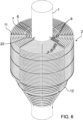
- FIGURE 1 illustrates a heat exchanger in accordance with at least some embodiments of the present invention.
- a heat exchanger tubing 2 is arranged around the core 1 and the heat exchanger tubing 2 is forms an outer borderline defining the shape of the heat exchanger tubing 2.
- the shape of the heat exchanger tubing 2 has a first part 4 formed as a cone and a second part 5 formed as a cylinder.
- the diameter of the cylinder is the same as the largest diameter of the cone, so these diameters match each other.
- a body 3 forms the outer casing of the heat exchanger.
- the outer surface of the body is cylindrical.
- the inner surface of the body is also cylindrical, but has a lining wall 13 extending from the inner surface of the cylinder towards the core 1.
- the lining wall 13 forms a cone funnel over the heat exchanger tubing 2 and the inner shape of the lining wall 13 follows the outer border line of the heat exchanger tubing at a distance, placing the inner wall of the body 3 parallel at a distance from the outer borderline of the heat exchanger tubing 2.
- the inner wall of the body 3 with the lining wall 13 and the outer surface of the core 1 form a flow path for a liquid.
- This liquid is the second liquid, that functions as a volume from which the heat is collected from or to which it is dissipated.
- the second liquid is usually water, as it is easily accessible in large enough volumes. However, any other liquid may be used, as long as the materials and structure of the heat exchanger is capable of handling such liquid, e.g. waste water, process water.
- the second liquid is fed to the heat exchanger through an intake 14 that is placed over the top of the heat exchanger tubing 2 when the heat exchanger is in vertical position in relation to the ground, i.e. the central axis of the core and the heat exchanger being placed on a right angle in relation to the ground. From the intake 14 the second liquid flows on a screen 15.
- the screen 15 is a plate having holes in it. This simple part effectively divides the second liquid over the heat exchanger tubing placed under it.
- the second liquid flows by the gravity downwards over the heat exchanger tubing and releases heat to the first liquid flowing in the heat exchanger tubing 2. Consequently the temperature of the second liquid decreases.
- the action is obviously the opposite.
- the heat exchanger may be used even in cold waters having temperature only few degrees above zero, even at a range from 0,5 - 5°C, freezing may be a problem.
- the second liquid flows on the bottom reservoir 16 of the body 3 and exits via outlet 17.
- the operation and setup of the heat exchanger is described herein in a vertical mounting and operation position.
- the apparatus may be operated and mounted horizontally, for example, or on an angle to the ground. If such mounting positions are used, forced feeding of second liquid may be needed. This applies to all assemblies when sufficient flow speed can't be achieved by gravity.
- the force feeding may be accomplished by pumping or using a liquid source placed on an elevated position in relation to the heat exchanger.
- the first liquid i.e. the liquid used for collecting or dissipating the heat energy
- the manifold 18 is connected to first ends 9 of each of the coil tubes 6, 7, 7xx of the heat exchanger tubing 2.
- the feed pipe 19 of the manifold 18 runs from the manifold 18 through the core to the top of the heat exchanger and therefrom to other parts of the heating/cooling system.
- the second ends 10 of the coil tubes 6, 7, 7xx are connected through a collector 20 to an exit pipe 21.
- the exit pipe also runs through the core 1.
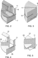
- the structure of the heat exchange tubing 2 is described in the following referring to FIGURES 2-6 .
- the core has axial brackets 22. herein 4, but other number might be used.
- On these brackets 22 are mounted axial divider walls 11. These axial divider walls 11?? divide the circumference of the heat exchanger tubing in sections, in this case quadrants.
- the coil tubes 6, 7, 7xx are mounted on these axial divider walls 11?.
- Each axial divider wall 11 is built of mounting strips 23.
- the mounting strips 23 have semi-circular seats 24 for a coil tube and fasteners for joining the mounting strips to the brackets and to each other.
- the seats may have other forms, for example oval or angular.
- the seat doesn't adapt closely to the outer cross section of the coil tube, the seats allow passage of water between eh mounting strip and the coil tube.
- the fasteners may be of any convenient kind, for example snap-on clips, rivets, screws, or glue. However, metal parts should be avoided in order to prevent risk of freezing and corrosion.
- the first mounting strips 23 (4 pcs) are fixed on the brackets of the core 1 and the first coil tube 6 is wound around the core 1 placing the coil tube in the seats 24 of the mounting strips 23.
- the first end 9 of the first coil tube is placed closest to the first end 8 of the core 1, i.e. closest to the bottom of the heat exchanger.
- the first coil tube 6 is would around the core until the top wherein the second end of the coil tube 10 is set on a set level.
- next mounting strip 23 may be attached to the previous one locking the first coil tube 6 on its place.
- the second coil tube 7 is would on the mounting strip 23, but now the first end 9 of the second coil tube 7 is set further away from the bottom of the heat exchanger.
- the second end 10 of the second coil tube 7 is set on the same level as the first coil tube 6.
- Further coil tubes 7xx are mounted in similar fashion by adding mounting strips and successive coil tubes.
- the first purpose of this structure is to form said cone shape to accommodate the conical shape of the inner wall of the body.
- the second purpose is to enable using coil tubes having same length.
- the first ends of the coil tubes are connected to a manifold 18 (18?) and the second ends to a collector 20.
- the second ends of the coil tubes are set on a same level.
- radial dividers 12 are set between the rounds of coil tubes.
- the radial dividers 12 are perforated plates mounted on axial divider walls 11. by trusses 25.
- the radial dividers 12 are set stepwise over the axial length of the heat exchanger tubing so that every other radial divider plate extends from the outer surface of the core 1 and every other from the inner wall of the body 3.
- Each of the radial divider plates extend only partially over the radial distance between the inner wall of the body and the outer surface of the body creating stepwise winding flow path. In this way the second liquid is mixed and its temperature is evened out.
- One feature relates to perforations of the radial dividers 12. The perforations allow second liquid to flow over the coil tube under the radial divider 12 so that the surface of the coil tube is not obscured by the axial divider plate.
- the apparatus described above and depicted in the drawings is configured by using parts that have circular cross section.
- Such parts like core, body and connecting pipelines can be conveniently obtained as they are or can be manufactured by using existing apparatuses of plastic industry.
- the core and body are made of parts having oval cross section.
- Such configuration may be needed to fit the heat exchanger in shallow heat sources. Any sharply angular cross sections like rectangular or hexagonal are to be avoided as they may create areas where flow speed is decreased, leading to decreased heat transfer and affinity to freezing.
- the preferred material of the heat exchanger is plastic, in particular polyethylene (PE), polypropylene (PP).
- PE polyethylene
- PP polypropylene
- the bottom of the heat exchanger can be made of a panel made of plastic profiles, e.g. UPONOR WEHOPANEL ® for example.
- the body may be made of tube made of wound profile.
- the second liquid is, for example ethanol. This allows for incoming temperatures of the first liquid as low as 0,5 - 1°C.
- the size of the heat exchanger dimensions of 2,4 m diameter, up to 3 - 4 m high, comprising 13 rounds of coil tubes each having length of 100 - 300 m, can be given. However, the dimensions may be adjusted as required.
- the structure of the heat exchanger enables dismantling for maintenance and transfer.
- the apparatus can be operated by gravity or the pressure may be elevated by pumping.
- the invention can be used for collecting or dissipating heat energy and for providing heat exchangers for collecting or dissipating heat energy.
Abstract
According to an example aspect of the present invention, there is provided a heat exchanger comprising a cylindrical core (1), a heat exchanger tubing (2) for a first liquid, a body (3, 13) surrounding the heat exchanger tubing (2), wherein the inner surface of the body (3) has the same shape as the outer borderline of the heat exchanger tubing (2), the heat exchanger tubing (2) having a first part (4) formed as a cone having first diameter and a second larger diameter, and a second part (5) formed as a cylinder having the same diameter as the second larger diameter of the cone, and the inner surface of the body (3) is formed as a shell around the heat exchanger tubing (2) and delineates with the core (19 a flow path for a second liquid.
Description
- The invention relates to heat exchangers, especially to heat exchangers for recovering and releasing heat from water. In particular, the invention relates to heat exchangers for recovering heat from water in low temperatures.
- Concerns related to global warming and increasing energy prices have heat pump technologies increasingly lucrative. In such systems energy is recovered from heat source by using compression-evaporation cycle. By these systems heat end energy can be collected from various sources even at very low temperatures. Typical energy sources are wastewater, exhaust air or gas flows, ground and water sources and air. The energy is collected to the compression-evaporation circuit by using a heat exchanger, various kinds of heat exchangers can be used for this purpose, the most usual types being plate- or tube heat exchangers. Typical materials are metals and plastics (polymers). When a heat exchanger is used in a cold environment, it should have a high heat transfer capability at low temperatures and good resistive for freezing. This makes designing and dimensioning such heat exchangers challenging.
- Examples of heat exchangers for low temperatures can be found in
EP 3117170 ,SE 165824 SU 785633 US 4735261 andWO 2012064387 . - The invention is defined by the features of the independent claims. Some specific embodiments are defined in the dependent claims.
- According to a first aspect of the present invention, there is provided a heat exchanger comprising a cylindrical core, a heat exchanger tubing for a first liquid, a body surrounding the heat exchanger tubing, wherein the inner surface of the body has the same shape as the outer borderline of the heat exchanger tubing. The heat exchanger tubing has a first part formed as a cone having first diameter and a second larger diameter, and a second part formed as a cylinder having the same diameter as the second larger diameter of the cone wherein the inner surface of the body forms a shell around the heat exchanger tubing and delineates with the core a flow path for a second liquid.
- According to a second aspect of the present invention, there is provided a method for producing heat exchanger, comprising:
- providing a core,
- attaching first brackets on the surface of the core,
- winding a first coil tube around the core and attaching it to the brackets,
- attaching second brackets on the first brackets,
- winding a second coil tube around the core and attaching it to the second brackets,
- adding further brackets and coil tubes as in previous steps,
- joining first ends of the coil tubes to a manifold,
- joining second ends 10 of the coil tubes to a collector,
- providing the heat exchanger with a covering body.
- According to a third aspect of the invention, there is provided a heat exchanger wherein all major parts are made of plastic, at least the parts forming and within the flow path of the second liquid.
- According to a fourth aspect of the invention there is provided a heat exchanger, wherein the heat exchanger tubing comprises a first coil tube coiled around the core and at least one second coil tube coiled around the first coil tube wherein the first end of the first coil tube is located at vicinity of the first end of the core and the first end of the second coil tube is located at a distance from the first end of the core that is greater than the distance between the first end of the first coil tube and the first end of the core so that the first ends of the coil tubes form a cone at the first end of the core and the second ends of the coil tubes are set on a same plane.
- According to a fifth aspect of the invention, the heat exchanger tubing comprises multiple successive coil tubes having first ends distanced gradually at longer distances from the first end of the core.
- According to a sixth aspect of the invention, the length of each coil tube is the same.
- According to a seventh aspect of the invention, there is provided a heat exchanger comprising at least one axial divider wall extending between the outer surface of the core and the inner surface of the body and having holes for coil tubes.
- According to an eighth aspect of the invention, there is provided a heat exchanger, comprising at least one radial divider extending from either the outer surface of the core or the inner surface of the body in between the coil tubes creating one or multiple flow paths for the second liquid.
- According to the ninth aspect of the invention there is provided a heat exchanger wherein the axial dividers comprise multiple holes.
- According to the tenth aspect of the invention there is provided a heat exchanger, wherein the coil tubes (6, 7, 7xx) are single continuous pipes without splices or joints.
-
-
FIGURE 1 illustrates as a cross section a heat exchanger in accordance with at least some embodiments of the present invention; -
FIGURE 2 illustrates a detail of the heat exchanger ofFIGURE 1 ; -
FIGURE 3 illustrates a detail of the heat exchanger ofFIGURE 1 ; -
FIGURE 4 illustrates a detail of the heat exchanger ofFIGURE 1 ; -
FIGURE 5 illustrates a detail of the heat exchanger ofFIGURE 1 ; and -
FIGURE 6 illustrates a partial assembly of the heat exchanger ofFIGURE 1 . - The heat exchanger described herein is primarily for collecting heat energy or for dissipating heat energy for cooling using sea- river or lake water or other water bodies having sufficient volume. The heat exchanger is usable in waters at low temperatures, even close to the freezing temperature. The heat exchanger is suitable for connecting to a heat pump system for either collecting heat to a heat pump circuit or for dissipating heat from the circuit. The heat exchanger has a flow path for the liquid from which the heat is collected or dissipated to formed so that the cross section of the flow path decreases in the flow direction, i.e. the direction on which the temperature of the second liquid decreases. A coil tube assembly for the first liquid is fitted in the flow path of the secondary liquid. The heat exchanger is preferably made of plastic, for example polyethylene or polypropylene.
-
FIGURE 1 illustrates a heat exchanger in accordance with at least some embodiments of the present invention. At the centre of the heat exchanger is a cylindrical core 1. Aheat exchanger tubing 2 is arranged around the core 1 and theheat exchanger tubing 2 is forms an outer borderline defining the shape of theheat exchanger tubing 2. The shape of theheat exchanger tubing 2 has afirst part 4 formed as a cone and asecond part 5 formed as a cylinder. The diameter of the cylinder is the same as the largest diameter of the cone, so these diameters match each other. Abody 3 forms the outer casing of the heat exchanger. The outer surface of the body is cylindrical. The inner surface of the body is also cylindrical, but has alining wall 13 extending from the inner surface of the cylinder towards the core 1. Thelining wall 13 forms a cone funnel over theheat exchanger tubing 2 and the inner shape of thelining wall 13 follows the outer border line of the heat exchanger tubing at a distance, placing the inner wall of thebody 3 parallel at a distance from the outer borderline of theheat exchanger tubing 2. The inner wall of thebody 3 with thelining wall 13 and the outer surface of the core 1 form a flow path for a liquid. This liquid is the second liquid, that functions as a volume from which the heat is collected from or to which it is dissipated. The second liquid is usually water, as it is easily accessible in large enough volumes. However, any other liquid may be used, as long as the materials and structure of the heat exchanger is capable of handling such liquid, e.g. waste water, process water. - The second liquid is fed to the heat exchanger through an
intake 14 that is placed over the top of theheat exchanger tubing 2 when the heat exchanger is in vertical position in relation to the ground, i.e. the central axis of the core and the heat exchanger being placed on a right angle in relation to the ground. From theintake 14 the second liquid flows on ascreen 15. Thescreen 15 is a plate having holes in it. This simple part effectively divides the second liquid over the heat exchanger tubing placed under it. The second liquid flows by the gravity downwards over the heat exchanger tubing and releases heat to the first liquid flowing in theheat exchanger tubing 2. Consequently the temperature of the second liquid decreases. When the heat exchanger is used for cooling, the action is obviously the opposite. As the temperature decreases, the heat transfer to the heat first liquid decreases. However, as the second liquid flows downwards the cross section of the flow path decreases as the second liquid reaches the cone part formed of the conicalfirst part 4 of theheat exchanger tubing 2 and the inner wall of thebody 3, formed at this section by the liningwall 13. This causes the flow speed of the second liquid to increase, increasing the heat transfer and keeping it on a steady level over theheat exchanger tubing 2. Another feature that is important when the heat exchanger is used in cold waters is that increasing flow speed reduces the risk of freezing that might occur when the temperature of the second liquid (water) is reduced. As the heat exchanger may be used even in cold waters having temperature only few degrees above zero, even at a range from 0,5 - 5°C, freezing may be a problem. From the conical part of thebody 3 the second liquid flows on thebottom reservoir 16 of thebody 3 and exits viaoutlet 17. - The operation and setup of the heat exchanger is described herein in a vertical mounting and operation position. The apparatus may be operated and mounted horizontally, for example, or on an angle to the ground. If such mounting positions are used, forced feeding of second liquid may be needed. This applies to all assemblies when sufficient flow speed can't be achieved by gravity. The force feeding may be accomplished by pumping or using a liquid source placed on an elevated position in relation to the heat exchanger.
- The first liquid, i.e. the liquid used for collecting or dissipating the heat energy, is fed to the
heat exchanger tubing 2 through a manifold 18 at thebottom reservoir 16. The manifold 18 is connected to first ends 9 of each of thecoil tubes heat exchanger tubing 2. Thefeed pipe 19 of the manifold 18 runs from the manifold 18 through the core to the top of the heat exchanger and therefrom to other parts of the heating/cooling system. The second ends 10 of thecoil tubes collector 20 to anexit pipe 21. The exit pipe also runs through the core 1. The location and arrangement of each of the feeding and exit of the first and second liquids are described herein as they are in the apparatus used as an example. The arrangement of these connecting assemblies have to be designed to adapt to the apparatus they are connected to. - The structure of the
heat exchange tubing 2 is described in the following referring toFIGURES 2-6 . The core hasaxial brackets 22. herein 4, but other number might be used. On thesebrackets 22 are mountedaxial divider walls 11. Theseaxial divider walls 11?? divide the circumference of the heat exchanger tubing in sections, in this case quadrants. Thecoil tubes axial divider walls 11?. Eachaxial divider wall 11 is built of mounting strips 23. The mounting strips 23 havesemi-circular seats 24 for a coil tube and fasteners for joining the mounting strips to the brackets and to each other. The seats may have other forms, for example oval or angular. It the seat doesn't adapt closely to the outer cross section of the coil tube, the seats allow passage of water between eh mounting strip and the coil tube. The fasteners may be of any convenient kind, for example snap-on clips, rivets, screws, or glue. However, metal parts should be avoided in order to prevent risk of freezing and corrosion. The first mounting strips 23 (4 pcs) are fixed on the brackets of the core 1 and thefirst coil tube 6 is wound around the core 1 placing the coil tube in theseats 24 of the mounting strips 23. The first end 9 of the first coil tube is placed closest to thefirst end 8 of the core 1, i.e. closest to the bottom of the heat exchanger. Thefirst coil tube 6 is would around the core until the top wherein the second end of the coil tube 10 is set on a set level. Now, the next mountingstrip 23 may be attached to the previous one locking thefirst coil tube 6 on its place. Thesecond coil tube 7 is would on the mountingstrip 23, but now the first end 9 of thesecond coil tube 7 is set further away from the bottom of the heat exchanger. The second end 10 of thesecond coil tube 7 is set on the same level as thefirst coil tube 6. Further coil tubes 7xx are mounted in similar fashion by adding mounting strips and successive coil tubes. As the first ends 9 of the coil tubes are gradually distanced from the bottom of the heat exchanger, the first ends and first rounds of the coil tubes form a cone shape. The first purpose of this structure is to form said cone shape to accommodate the conical shape of the inner wall of the body. The second purpose is to enable using coil tubes having same length. As the diameter of the coil tube winds increases when successive coil tubes are added, it must be accommodated by shortening the number of winds in direction parallel to the core. This structure enables using coil tubes of equal length. As the lengths of the coil tubes are the same, the flow resistance is the same and no valves are needed to accommodate different flow resistances. - As described above, the first ends of the coil tubes are connected to a manifold 18 (18?) and the second ends to a
collector 20. The second ends of the coil tubes are set on a same level. - In order to obtain a consistent flow of liquid over the whole area of the
heat exchanger tubing 2,radial dividers 12 are set between the rounds of coil tubes. Theradial dividers 12 are perforated plates mounted onaxial divider walls 11. by trusses 25. Theradial dividers 12 are set stepwise over the axial length of the heat exchanger tubing so that every other radial divider plate extends from the outer surface of the core 1 and every other from the inner wall of thebody 3. Each of the radial divider plates extend only partially over the radial distance between the inner wall of the body and the outer surface of the body creating stepwise winding flow path. In this way the second liquid is mixed and its temperature is evened out. More importantly, the flow speed over the flow path can be maintained sufficient for preventing freezing over whole are of the flow path. Also, mixed flow provides better heat transfer. One feature relates to perforations of theradial dividers 12. The perforations allow second liquid to flow over the coil tube under theradial divider 12 so that the surface of the coil tube is not obscured by the axial divider plate. - The apparatus described above and depicted in the drawings is configured by using parts that have circular cross section. Such parts, like core, body and connecting pipelines can be conveniently obtained as they are or can be manufactured by using existing apparatuses of plastic industry. However, it can be contemplated that, for example, the core and body are made of parts having oval cross section. Such configuration may be needed to fit the heat exchanger in shallow heat sources. Any sharply angular cross sections like rectangular or hexagonal are to be avoided as they may create areas where flow speed is decreased, leading to decreased heat transfer and affinity to freezing.
- The preferred material of the heat exchanger is plastic, in particular polyethylene (PE), polypropylene (PP). The parts contacting the second liquid, especially if it is water at low temperature, should be made of plastic. At higher temperatures this may not be essential. Metals also corrode. The bottom of the heat exchanger can be made of a panel made of plastic profiles, e.g. UPONOR WEHOPANEL® for example. The body may be made of tube made of wound profile. The second liquid is, for example ethanol. This allows for incoming temperatures of the first liquid as low as 0,5 - 1°C. As example of the size of the heat exchanger dimensions of 2,4 m diameter, up to 3 - 4 m high, comprising 13 rounds of coil tubes each having length of 100 - 300 m, can be given. However, the dimensions may be adjusted as required. The structure of the heat exchanger enables dismantling for maintenance and transfer. The apparatus can be operated by gravity or the pressure may be elevated by pumping.
- It is to be understood that the embodiments of the invention disclosed are not limited to the particular structures, process steps, or materials disclosed herein, but are extended to equivalents thereof as would be recognized by those ordinarily skilled in the relevant arts. It should also be understood that terminology employed herein is used for the purpose of describing particular embodiments only and is not intended to be limiting.
- Reference throughout this specification to "one embodiment" or "an embodiment" means that a particular feature, structure, or characteristic described in connection with the embodiment is included in at least one embodiment of the present invention. Thus, appearances of the phrases "in one embodiment" or "in an embodiment" in various places throughout this specification are not necessarily all referring to the same embodiment.
- As used herein, a plurality of items, structural elements, compositional elements, and/or materials may be presented in a common list for convenience. However, these lists should be construed as though each member of the list is individually identified as a separate and unique member. Thus, no individual member of such list should be construed as a de facto equivalent of any other member of the same list solely based on their presentation in a common group without indications to the contrary. In addition, various embodiments and example of the present invention may be referred to herein along with alternatives for the various components thereof. It is understood that such embodiments, examples, and alternatives are not to be construed as de facto equivalents of one another, but are to be considered as separate and autonomous representations of the present invention.
- Furthermore, the described features, structures, or characteristics may be combined in any suitable manner in one or more embodiments. In the following description, numerous specific details are provided, such as examples of lengths, widths, shapes, etc., to provide a thorough understanding of embodiments of the invention. One skilled in the relevant art will recognize, however, that the invention can be practiced without one or more of the specific details, or with other methods, components, materials, etc. In other instances, well-known structures, materials, or operations are not shown or described in detail to avoid obscuring aspects of the invention.
- While the forgoing examples are illustrative of the principles of the present invention in one or more particular applications, it will be apparent to those of ordinary skill in the art that numerous modifications in form, usage and details of implementation can be made without the exercise of inventive faculty, and without departing from the principles and concepts of the invention. Accordingly, it is not intended that the invention be limited, except as by the claims set forth below.
- The verbs "to comprise" and "to include" are used in this document as open limitations that neither exclude nor require the existence of also un-recited features. The features recited in depending claims are mutually freely combinable unless otherwise explicitly stated. Furthermore, it is to be understood that the use of "a" or "an", i.e. a singular form, throughout this document does not exclude a plurality.
- The invention can be used for collecting or dissipating heat energy and for providing heat exchangers for collecting or dissipating heat energy.
-
- 1
- core
- 2
- heat exchanger tubing
- 3
- body
- 4
- first part
- 5
- second part
- 6
- first coil tube
- 7
- second coil tube (7xx further coil tubes)
- 8
- first end of core
- 9
- first end of coil tube
- 10
- second end of coil tube
- 11
- axial divider wall
- 12
- radial divider
- 13
- lining wall
- 14
- intake
- 15
- screen
- 16
- bottom reservoir
- 17
- outlet
- 18
- manifold
- 19
- feed pipe
- 20
- collector
- 21
- exit pipe
- 22
- brackets
- 23
- mounting strips
- 24
- seat
- 25
- truss
-
Claims (12)
- A heat exchanger comprising:- a core (1)- a heat exchanger tubing (2) for a first liquid,- a body (3, 13) surrounding the heat exchanger tubing (2), wherein the inner surface of the body (3) has the same shape as the outer borderline of the heat exchanger tubing (2),characterized in that- the heat exchanger tubing (2) has a first part (4) formed as a cone having first diameter and a second larger diameter, and a second part (5) formed as a cylinder having the same diameter as the second larger diameter of the cone, and- the inner surface of the body (3) is formed as a shell around the heat exchanger tubing (2) and delineates with the core (1) a flow path for a second liquid.
- A heat exchanger according to the claim 1, wherein all major parts are made of plastic, at least the parts forming and within the flow path of the second liquid.
- A heat exchanger according to the claim 1 or 2,wherein the cross section of at least the core (1) and the outer surface of the body (3) is circular or oval.
- A heat exchanger according to one of the claims 1 or 2, wherein the heat exchanger tubing (2) comprises- a first coil tube (6) coiled around the core (1), and- at least one second coil tube (7) coiled around the first coil tube (6) wherein- the first end (9) of the first coil tube (6) is located at vicinity of the first end of the core (8) the first end (9) of the second coil tube (7) is located at a distance from the first end of the core (8) that is greater than the distance between the first end (9) of the first coil tube (6) and the first end of the core (8) so that the coil tubes (6, 7, 7xx) form a cone at the first end of the core (8) and the second ends (10) of the coil tubes (6, 7, 7xx) are set on a same plane.
- A heat exchanger according to the claim 3, wherein the heat exchanger tubing (2) comprises multiple successive coil tubes (6, 7, 7xx) having first ends (9) distanced gradually at longer distances from the first end of the core (8).
- A heat exchanger according to one of the claims 3 or 4 wherein the length of each coil tube (6, 7, 7xx) is the same.
- A heat exchanger according to one of the claims 3 or 4 wherein the length of each coil tube (6, 7, 7xx) is 50 - 300 m.
- A heat exchanger according to any of the claims 3-5, comprising at least one axial divider wall (11) extending between the outer surface of the core (1) and the inner surface of the body (3) and having seats (24) for coil tubes (6, 7, 7xx).
- A heat exchanger according to one of the claims 1-6, comprising at least one radial divider (12) extending from either the outer surface of the core (1) or the inner surface of the body (3) in between the coil tubes (6, 7, 7xx) creating a one or multiple flow paths for the second liquid.
- A heat exchanger according to the claim 7, wherein the axial dividers (12) comprise multiple holes.
- A heat exchanger according to one of the claims 3-8, wherein the coil tubes (6, 7, 7xx) are single continuous pipes without splices or joints.
- A method for producing heat exchanger, comprising:- providing a core (1),- attaching first brackets (22) on the surface of the core,- winding a first coil tube (6) around the core (1) and attaching it to the brackets (22),- attaching second brackets (22) on the first brackets (22),- winding a second coil tube around the core (1) and attaching it to the second brackets (22),- adding further brackets (22) and coil tubes (7xx) as in previous steps,- joining first ends (9) of the coil tubes (6, 7, 7xx) to a manifold,- joining second ends 10 of the coil tubes (6, 7, 7xx) to a collector (20),- providing the heat exchanger with a covering body (3).
Applications Claiming Priority (1)
| Application Number | Priority Date | Filing Date | Title |
|---|---|---|---|
| FI20225776A FI20225776A1 (en) | 2022-09-05 | 2022-09-05 | Heat exchanger and method for its production |
Publications (1)
| Publication Number | Publication Date |
|---|---|
| EP4332486A1 true EP4332486A1 (en) | 2024-03-06 |
Family
ID=87930027
Family Applications (1)
| Application Number | Title | Priority Date | Filing Date |
|---|---|---|---|
| EP23195078.3A Pending EP4332486A1 (en) | 2022-09-05 | 2023-09-04 | Heat exchanger and a method for its production |
Country Status (2)
| Country | Link |
|---|---|
| EP (1) | EP4332486A1 (en) |
| FI (1) | FI20225776A1 (en) |
Citations (12)
| Publication number | Priority date | Publication date | Assignee | Title |
|---|---|---|---|---|
| SE165824C1 (en) | ||||
| FR2128127A1 (en) * | 1971-03-05 | 1972-10-20 | Bignier Schmid Laurent | |
| SU785633A1 (en) | 1979-01-18 | 1980-12-07 | Предприятие П/Я Р-6273 | Horizontal modular heat exchanger |
| EP0146817A2 (en) * | 1983-12-21 | 1985-07-03 | Laporte Industries Limited | Heat exchanger |
| US4735261A (en) | 1982-09-13 | 1988-04-05 | Plascore, Inc. | Plastic heat exchanger |
| EP0874209A1 (en) * | 1997-04-24 | 1998-10-28 | Giorgio Scanferla | Heat exchanger for water heating apparatuses and method for producing the same |
| US20100096115A1 (en) * | 2008-10-07 | 2010-04-22 | Donald Charles Erickson | Multiple concentric cylindrical co-coiled heat exchanger |
| WO2012064387A1 (en) | 2010-11-08 | 2012-05-18 | Geoenergy Enterprises, Llc | Method of heating/cooling structure using geothermal system |
| EP3063489A1 (en) * | 2013-10-31 | 2016-09-07 | Heat Recovery Solutions Limited | Heat exchange array |
| EP3117170A1 (en) | 2014-03-04 | 2017-01-18 | Uponor Infra Oy | Heat exchanger for low temperatures |
| CN109612303A (en) * | 2019-01-25 | 2019-04-12 | 安徽理工大学 | A kind of high efficiency votator for air-conditioning |
| WO2021144682A1 (en) * | 2020-01-13 | 2021-07-22 | Stamenic Aleksandar | Energy exchange device between media with improved structure and performances |
-
2022
- 2022-09-05 FI FI20225776A patent/FI20225776A1/en unknown
-
2023
- 2023-09-04 EP EP23195078.3A patent/EP4332486A1/en active Pending
Patent Citations (12)
| Publication number | Priority date | Publication date | Assignee | Title |
|---|---|---|---|---|
| SE165824C1 (en) | ||||
| FR2128127A1 (en) * | 1971-03-05 | 1972-10-20 | Bignier Schmid Laurent | |
| SU785633A1 (en) | 1979-01-18 | 1980-12-07 | Предприятие П/Я Р-6273 | Horizontal modular heat exchanger |
| US4735261A (en) | 1982-09-13 | 1988-04-05 | Plascore, Inc. | Plastic heat exchanger |
| EP0146817A2 (en) * | 1983-12-21 | 1985-07-03 | Laporte Industries Limited | Heat exchanger |
| EP0874209A1 (en) * | 1997-04-24 | 1998-10-28 | Giorgio Scanferla | Heat exchanger for water heating apparatuses and method for producing the same |
| US20100096115A1 (en) * | 2008-10-07 | 2010-04-22 | Donald Charles Erickson | Multiple concentric cylindrical co-coiled heat exchanger |
| WO2012064387A1 (en) | 2010-11-08 | 2012-05-18 | Geoenergy Enterprises, Llc | Method of heating/cooling structure using geothermal system |
| EP3063489A1 (en) * | 2013-10-31 | 2016-09-07 | Heat Recovery Solutions Limited | Heat exchange array |
| EP3117170A1 (en) | 2014-03-04 | 2017-01-18 | Uponor Infra Oy | Heat exchanger for low temperatures |
| CN109612303A (en) * | 2019-01-25 | 2019-04-12 | 安徽理工大学 | A kind of high efficiency votator for air-conditioning |
| WO2021144682A1 (en) * | 2020-01-13 | 2021-07-22 | Stamenic Aleksandar | Energy exchange device between media with improved structure and performances |
Also Published As
| Publication number | Publication date |
|---|---|
| FI20225776A1 (en) | 2024-03-06 |
Similar Documents
| Publication | Publication Date | Title |
|---|---|---|
| EP2821745A1 (en) | Heat-exchange apparatus | |
| EP1971815B1 (en) | Spirally wound, layered tube heat exchanger | |
| CN103822510B (en) | Muitishell tubular heat exchanger | |
| CN101013009A (en) | Combined helix baffle plate shell-and-tube heat exchanger | |
| US20110139422A1 (en) | Fluid distribution device | |
| CN101619944A (en) | Heat exchanger with corrugated pipe coil structure provided with internal duct and external duct | |
| WO2012085337A1 (en) | A shell and tube heat exchanger | |
| EP2914383A1 (en) | Nozzle for distribution of a fluid | |
| CN104913663A (en) | Tube shell pass volume-adjustable longitudinal turbulence oil cooler | |
| EP4332486A1 (en) | Heat exchanger and a method for its production | |
| EP3314191A1 (en) | Two phase distributor evaporator | |
| CN110567298A (en) | Nested formula spiral baffling board and heat exchanger | |
| CN103278033B (en) | High-effect energy-saving heat-exchanger | |
| CN212390898U (en) | Liquid separation structure and heat exchanger | |
| CN111912283A (en) | Liquid separation structure and heat exchanger | |
| CN211886295U (en) | Gas mixer | |
| CN203349686U (en) | Tubular heat exchanger and continuous composite spiral baffle plate thereof | |
| CN201449085U (en) | Heat exchanging system | |
| US20160161190A1 (en) | Collector pipe for a heat exchanger device, a heat exchanger device and a method for emptying a heat exchanger device | |
| CN100533037C (en) | Continuous spiral traverse baffle double shell side combined special-shaped tube bundle heat exchanger | |
| CN211012552U (en) | Pipeline heat exchanger | |
| CN203848733U (en) | Round microchannel heat exchange aluminum part | |
| CN209069049U (en) | A kind of high-performance heat exchanger | |
| RU2572545C1 (en) | Shell-and-tube continuous heat exchanger | |
| RU117595U1 (en) | HEAT EXCHANGE DEVICE |
Legal Events
| Date | Code | Title | Description |
|---|---|---|---|
| PUAI | Public reference made under article 153(3) epc to a published international application that has entered the european phase |
Free format text: ORIGINAL CODE: 0009012 |
|
| STAA | Information on the status of an ep patent application or granted ep patent |
Free format text: STATUS: THE APPLICATION HAS BEEN PUBLISHED |
|
| AK | Designated contracting states |
Kind code of ref document: A1 Designated state(s): AL AT BE BG CH CY CZ DE DK EE ES FI FR GB GR HR HU IE IS IT LI LT LU LV MC ME MK MT NL NO PL PT RO RS SE SI SK SM TR |