EP4332401B1 - Ausrichtungswerkzeug - Google Patents
Ausrichtungswerkzeug Download PDFInfo
- Publication number
- EP4332401B1 EP4332401B1 EP23174179.4A EP23174179A EP4332401B1 EP 4332401 B1 EP4332401 B1 EP 4332401B1 EP 23174179 A EP23174179 A EP 23174179A EP 4332401 B1 EP4332401 B1 EP 4332401B1
- Authority
- EP
- European Patent Office
- Prior art keywords
- motor
- plug
- gearbox
- cap screw
- alignment
- Prior art date
- Legal status (The legal status is an assumption and is not a legal conclusion. Google has not performed a legal analysis and makes no representation as to the accuracy of the status listed.)
- Active
Links
Images


Classifications
-
- F—MECHANICAL ENGINEERING; LIGHTING; HEATING; WEAPONS; BLASTING
- F01—MACHINES OR ENGINES IN GENERAL; ENGINE PLANTS IN GENERAL; STEAM ENGINES
- F01D—NON-POSITIVE DISPLACEMENT MACHINES OR ENGINES, e.g. STEAM TURBINES
- F01D25/00—Component parts, details, or accessories, not provided for in, or of interest apart from, other groups
- F01D25/28—Supporting or mounting arrangements, e.g. for turbine casing
- F01D25/285—Temporary support structures, e.g. for testing, assembling, installing, repairing; Assembly methods using such structures
-
- F—MECHANICAL ENGINEERING; LIGHTING; HEATING; WEAPONS; BLASTING
- F16—ENGINEERING ELEMENTS AND UNITS; GENERAL MEASURES FOR PRODUCING AND MAINTAINING EFFECTIVE FUNCTIONING OF MACHINES OR INSTALLATIONS; THERMAL INSULATION IN GENERAL
- F16D—COUPLINGS FOR TRANSMITTING ROTATION; CLUTCHES; BRAKES
- F16D1/00—Couplings for rigidly connecting two coaxial shafts or other movable machine elements
- F16D1/10—Quick-acting couplings in which the parts are connected by simply bringing them together axially
-
- F—MECHANICAL ENGINEERING; LIGHTING; HEATING; WEAPONS; BLASTING
- F16—ENGINEERING ELEMENTS AND UNITS; GENERAL MEASURES FOR PRODUCING AND MAINTAINING EFFECTIVE FUNCTIONING OF MACHINES OR INSTALLATIONS; THERMAL INSULATION IN GENERAL
- F16B—DEVICES FOR FASTENING OR SECURING CONSTRUCTIONAL ELEMENTS OR MACHINE PARTS TOGETHER, e.g. NAILS, BOLTS, CIRCLIPS, CLAMPS, CLIPS OR WEDGES; JOINTS OR JOINTING
- F16B23/00—Specially shaped nuts or heads of bolts or screws for rotations by a tool
- F16B23/0007—Specially shaped nuts or heads of bolts or screws for rotations by a tool characterised by the shape of the recess or the protrusion engaging the tool
- F16B23/0038—Specially shaped nuts or heads of bolts or screws for rotations by a tool characterised by the shape of the recess or the protrusion engaging the tool substantially prismatic with up to six edges, e.g. triangular, square, pentagonal, Allen-type cross-sections
-
- F—MECHANICAL ENGINEERING; LIGHTING; HEATING; WEAPONS; BLASTING
- F04—POSITIVE - DISPLACEMENT MACHINES FOR LIQUIDS; PUMPS FOR LIQUIDS OR ELASTIC FLUIDS
- F04B—POSITIVE-DISPLACEMENT MACHINES FOR LIQUIDS; PUMPS
- F04B17/00—Pumps characterised by combination with, or adaptation to, specific driving engines or motors
-
- F—MECHANICAL ENGINEERING; LIGHTING; HEATING; WEAPONS; BLASTING
- F04—POSITIVE - DISPLACEMENT MACHINES FOR LIQUIDS; PUMPS FOR LIQUIDS OR ELASTIC FLUIDS
- F04B—POSITIVE-DISPLACEMENT MACHINES FOR LIQUIDS; PUMPS
- F04B17/00—Pumps characterised by combination with, or adaptation to, specific driving engines or motors
- F04B17/03—Pumps characterised by combination with, or adaptation to, specific driving engines or motors driven by electric motors
-
- F—MECHANICAL ENGINEERING; LIGHTING; HEATING; WEAPONS; BLASTING
- F04—POSITIVE - DISPLACEMENT MACHINES FOR LIQUIDS; PUMPS FOR LIQUIDS OR ELASTIC FLUIDS
- F04B—POSITIVE-DISPLACEMENT MACHINES FOR LIQUIDS; PUMPS
- F04B17/00—Pumps characterised by combination with, or adaptation to, specific driving engines or motors
- F04B17/05—Pumps characterised by combination with, or adaptation to, specific driving engines or motors driven by internal-combustion engines
-
- F—MECHANICAL ENGINEERING; LIGHTING; HEATING; WEAPONS; BLASTING
- F04—POSITIVE - DISPLACEMENT MACHINES FOR LIQUIDS; PUMPS FOR LIQUIDS OR ELASTIC FLUIDS
- F04B—POSITIVE-DISPLACEMENT MACHINES FOR LIQUIDS; PUMPS
- F04B35/00—Piston pumps specially adapted for elastic fluids and characterised by the driving means to their working members, or by combination with, or adaptation to, specific driving engines or motors, not otherwise provided for
-
- F—MECHANICAL ENGINEERING; LIGHTING; HEATING; WEAPONS; BLASTING
- F04—POSITIVE - DISPLACEMENT MACHINES FOR LIQUIDS; PUMPS FOR LIQUIDS OR ELASTIC FLUIDS
- F04B—POSITIVE-DISPLACEMENT MACHINES FOR LIQUIDS; PUMPS
- F04B35/00—Piston pumps specially adapted for elastic fluids and characterised by the driving means to their working members, or by combination with, or adaptation to, specific driving engines or motors, not otherwise provided for
- F04B35/002—Piston pumps specially adapted for elastic fluids and characterised by the driving means to their working members, or by combination with, or adaptation to, specific driving engines or motors, not otherwise provided for driven by internal combustion engines
-
- F—MECHANICAL ENGINEERING; LIGHTING; HEATING; WEAPONS; BLASTING
- F04—POSITIVE - DISPLACEMENT MACHINES FOR LIQUIDS; PUMPS FOR LIQUIDS OR ELASTIC FLUIDS
- F04B—POSITIVE-DISPLACEMENT MACHINES FOR LIQUIDS; PUMPS
- F04B35/00—Piston pumps specially adapted for elastic fluids and characterised by the driving means to their working members, or by combination with, or adaptation to, specific driving engines or motors, not otherwise provided for
- F04B35/006—Piston pumps specially adapted for elastic fluids and characterised by the driving means to their working members, or by combination with, or adaptation to, specific driving engines or motors, not otherwise provided for driven by steam engines
-
- F—MECHANICAL ENGINEERING; LIGHTING; HEATING; WEAPONS; BLASTING
- F04—POSITIVE - DISPLACEMENT MACHINES FOR LIQUIDS; PUMPS FOR LIQUIDS OR ELASTIC FLUIDS
- F04B—POSITIVE-DISPLACEMENT MACHINES FOR LIQUIDS; PUMPS
- F04B35/00—Piston pumps specially adapted for elastic fluids and characterised by the driving means to their working members, or by combination with, or adaptation to, specific driving engines or motors, not otherwise provided for
- F04B35/04—Piston pumps specially adapted for elastic fluids and characterised by the driving means to their working members, or by combination with, or adaptation to, specific driving engines or motors, not otherwise provided for the means being electric
-
- F—MECHANICAL ENGINEERING; LIGHTING; HEATING; WEAPONS; BLASTING
- F04—POSITIVE - DISPLACEMENT MACHINES FOR LIQUIDS; PUMPS FOR LIQUIDS OR ELASTIC FLUIDS
- F04D—NON-POSITIVE-DISPLACEMENT PUMPS
- F04D25/00—Pumping installations or systems
- F04D25/02—Units comprising pumps and their driving means
-
- F—MECHANICAL ENGINEERING; LIGHTING; HEATING; WEAPONS; BLASTING
- F04—POSITIVE - DISPLACEMENT MACHINES FOR LIQUIDS; PUMPS FOR LIQUIDS OR ELASTIC FLUIDS
- F04D—NON-POSITIVE-DISPLACEMENT PUMPS
- F04D25/00—Pumping installations or systems
- F04D25/02—Units comprising pumps and their driving means
- F04D25/06—Units comprising pumps and their driving means the pump being electrically driven
-
- F—MECHANICAL ENGINEERING; LIGHTING; HEATING; WEAPONS; BLASTING
- F04—POSITIVE - DISPLACEMENT MACHINES FOR LIQUIDS; PUMPS FOR LIQUIDS OR ELASTIC FLUIDS
- F04D—NON-POSITIVE-DISPLACEMENT PUMPS
- F04D25/00—Pumping installations or systems
- F04D25/02—Units comprising pumps and their driving means
- F04D25/08—Units comprising pumps and their driving means the working fluid being air, e.g. for ventilation
-
- F—MECHANICAL ENGINEERING; LIGHTING; HEATING; WEAPONS; BLASTING
- F16—ENGINEERING ELEMENTS AND UNITS; GENERAL MEASURES FOR PRODUCING AND MAINTAINING EFFECTIVE FUNCTIONING OF MACHINES OR INSTALLATIONS; THERMAL INSULATION IN GENERAL
- F16H—GEARING
- F16H57/00—General details of gearing
- F16H57/02—Gearboxes; Mounting gearing therein
-
- H—ELECTRICITY
- H02—GENERATION; CONVERSION OR DISTRIBUTION OF ELECTRIC POWER
- H02K—DYNAMO-ELECTRIC MACHINES
- H02K15/00—Processes or apparatus specially adapted for manufacturing, assembling, maintaining or repairing of dynamo-electric machines
-
- H—ELECTRICITY
- H02—GENERATION; CONVERSION OR DISTRIBUTION OF ELECTRIC POWER
- H02K—DYNAMO-ELECTRIC MACHINES
- H02K15/00—Processes or apparatus specially adapted for manufacturing, assembling, maintaining or repairing of dynamo-electric machines
- H02K15/14—Casings; Enclosures; Supports
-
- H—ELECTRICITY
- H02—GENERATION; CONVERSION OR DISTRIBUTION OF ELECTRIC POWER
- H02K—DYNAMO-ELECTRIC MACHINES
- H02K7/00—Arrangements for handling mechanical energy structurally associated with dynamo-electric machines, e.g. structural association with mechanical driving motors or auxiliary dynamo-electric machines
- H02K7/003—Couplings; Details of shafts
-
- H—ELECTRICITY
- H02—GENERATION; CONVERSION OR DISTRIBUTION OF ELECTRIC POWER
- H02K—DYNAMO-ELECTRIC MACHINES
- H02K7/00—Arrangements for handling mechanical energy structurally associated with dynamo-electric machines, e.g. structural association with mechanical driving motors or auxiliary dynamo-electric machines
- H02K7/10—Structural association with clutches, brakes, gears, pulleys or mechanical starters
- H02K7/116—Structural association with clutches, brakes, gears, pulleys or mechanical starters with gears
-
- H—ELECTRICITY
- H02—GENERATION; CONVERSION OR DISTRIBUTION OF ELECTRIC POWER
- H02K—DYNAMO-ELECTRIC MACHINES
- H02K7/00—Arrangements for handling mechanical energy structurally associated with dynamo-electric machines, e.g. structural association with mechanical driving motors or auxiliary dynamo-electric machines
- H02K7/14—Structural association with mechanical loads, e.g. with hand-held machine tools or fans
-
- F—MECHANICAL ENGINEERING; LIGHTING; HEATING; WEAPONS; BLASTING
- F05—INDEXING SCHEMES RELATING TO ENGINES OR PUMPS IN VARIOUS SUBCLASSES OF CLASSES F01-F04
- F05D—INDEXING SCHEME FOR ASPECTS RELATING TO NON-POSITIVE-DISPLACEMENT MACHINES OR ENGINES, GAS-TURBINES OR JET-PROPULSION PLANTS
- F05D2230/00—Manufacture
- F05D2230/60—Assembly methods
- F05D2230/64—Assembly methods using positioning or alignment devices for aligning or centring, e.g. pins
- F05D2230/644—Assembly methods using positioning or alignment devices for aligning or centring, e.g. pins for adjusting the position or the alignment, e.g. wedges or eccenters
-
- F—MECHANICAL ENGINEERING; LIGHTING; HEATING; WEAPONS; BLASTING
- F05—INDEXING SCHEMES RELATING TO ENGINES OR PUMPS IN VARIOUS SUBCLASSES OF CLASSES F01-F04
- F05D—INDEXING SCHEME FOR ASPECTS RELATING TO NON-POSITIVE-DISPLACEMENT MACHINES OR ENGINES, GAS-TURBINES OR JET-PROPULSION PLANTS
- F05D2240/00—Components
- F05D2240/60—Shafts
-
- F—MECHANICAL ENGINEERING; LIGHTING; HEATING; WEAPONS; BLASTING
- F16—ENGINEERING ELEMENTS AND UNITS; GENERAL MEASURES FOR PRODUCING AND MAINTAINING EFFECTIVE FUNCTIONING OF MACHINES OR INSTALLATIONS; THERMAL INSULATION IN GENERAL
- F16D—COUPLINGS FOR TRANSMITTING ROTATION; CLUTCHES; BRAKES
- F16D2300/00—Special features for couplings or clutches
- F16D2300/12—Mounting or assembling
-
- F—MECHANICAL ENGINEERING; LIGHTING; HEATING; WEAPONS; BLASTING
- F16—ENGINEERING ELEMENTS AND UNITS; GENERAL MEASURES FOR PRODUCING AND MAINTAINING EFFECTIVE FUNCTIONING OF MACHINES OR INSTALLATIONS; THERMAL INSULATION IN GENERAL
- F16H—GEARING
- F16H57/00—General details of gearing
- F16H2057/0062—Tools specially adapted for assembly of transmissions
-
- F—MECHANICAL ENGINEERING; LIGHTING; HEATING; WEAPONS; BLASTING
- F16—ENGINEERING ELEMENTS AND UNITS; GENERAL MEASURES FOR PRODUCING AND MAINTAINING EFFECTIVE FUNCTIONING OF MACHINES OR INSTALLATIONS; THERMAL INSULATION IN GENERAL
- F16H—GEARING
- F16H57/00—General details of gearing
- F16H57/02—Gearboxes; Mounting gearing therein
- F16H2057/02021—Gearboxes; Mounting gearing therein with means for adjusting alignment
-
- F—MECHANICAL ENGINEERING; LIGHTING; HEATING; WEAPONS; BLASTING
- F16—ENGINEERING ELEMENTS AND UNITS; GENERAL MEASURES FOR PRODUCING AND MAINTAINING EFFECTIVE FUNCTIONING OF MACHINES OR INSTALLATIONS; THERMAL INSULATION IN GENERAL
- F16H—GEARING
- F16H57/00—General details of gearing
- F16H57/02—Gearboxes; Mounting gearing therein
- F16H2057/02034—Gearboxes combined or connected with electric machines
Definitions
- This disclosure relates generally to alignment and, more particularly, to tools for alignment of a driver and a driven component.
- Rotating machinery often includes a driver and driven components.
- the driver and the driven components may be connected by a shaft. Proper alignment of the shaft is an important factor in ensuring proper function of the rotating machinery.
- WO2018/055427A1 provides a prior art example of a tool for use with a belted sheave system and a method of use.
- connection references e.g., attached, coupled, connected, and joined
- connection references may include intermediate members between the elements referenced by the connection reference and/or relative movement between those elements unless otherwise indicated.
- connection references do not necessarily infer that two elements are directly connected and/or in fixed relation to each other.
- descriptors such as “first,” “second,” “third,” etc. are used herein without imputing or otherwise indicating any meaning of priority, physical order, arrangement in a list, and/or ordering in any way, but are merely used as labels and/or arbitrary names to distinguish elements for ease of understanding the disclosed examples.
- the descriptor "first” may be used to refer to an element in the detailed description, while the same element may be referred to in a claim with a different descriptor such as "second” or “third.” In such instances, it should be understood that such descriptors are used merely for identifying those elements distinctly that might, for example, otherwise share a same name.
- Rotating machinery such as pumps, turbines, compressors, gears, and fans all include rotating shafts.
- the rotating shafts operate at high revolutions per minute (RPM), connecting a driver and driven elements.
- RPM revolutions per minute
- Some modem rotating machinery operates at an extremely high speed (e.g., 40,000 RPM). In such machinery, proper shaft alignment is necessary to ensure effective operation of the rotating machinery. Improper shaft alignment can be associated with increased temperatures, excessive lubricant leakage, premature wear, and failure of the shaft. Rotating equipment with a misaligned shaft can also be dangerous. Improperly aligned shafts may cause excessive vibrations that lead to coupling failures, which may expel machine components from the rotating machinery at high speeds.
- Conventional alignment solutions are often based on alignment of male shafts extending from each of the driver and the driven elements.
- a coarse alignment can be achieved by aligning protruding shafts by moving a machine base, shimming the machinery, etc.
- a dial indicator can confirm the alignment and/or facilitate measurements and determine any desired adjustments.
- a flexible coupling may lock the shafts together.
- Disclosed examples include an alignment tool for a motor-driven propeller (MDP) gearbox.
- the motor-driven propeller includes both a motor and a gearbox that each have female splined shafts, with an intermediate rotating shaft connecting the motor and the gearbox.
- the motor-driven propeller drivetrain does not include shafts that protrude from the motor or the gearbox, conventional solutions fail to achieve accurate alignment of the motor-driven propeller.
- Disclosed examples include a first alignment tool with a first shaft and an expandable elastomer plug that is inserted into the gearbox.
- the expandable elastomer plug can be formed of urethane, rubber, silicone, etc.
- Some examples include a second alignment tool with a second shaft and a second expandable elastomer plug that is inserted into the motor. Expansion of the expandable plugs secures each respective alignment tool in place. The expansion occurs due to the Poisson's ratio of the plug and axial compression of the plug.
- the example MDP motor and the MDP propeller are then pinned in location. Removing either the motor or the gearbox allows the rotating shaft to be inserted. The removed motor or gearbox is re-installed using the pinned location.
- a motor may have a female splined shaft for alignment with a male stub shaft extending from a gearbox.
- a single alignment tool may be inserted into the gearbox and aligned with the male stub shaft.
- a gearbox may have a female splined shaft for alignment with a male stub shaft extending from a motor. In such an example, a single alignment tool may be inserted into the motor and aligned with the male stub shaft.
- Hybrid aircraft drivetrains in the field may include a motor-driven shaft that has become misaligned due to removal of one or both components for maintenance.
- Motor-driven alignment tools may also be used to align newly installed and/or replacement motors in the hybrid electric aircraft. Therefore, disclosed examples may be provided to maintenance/repair teams as a part of an aircraft repair toolset.
- the alignment tools described herein are not limited to use with motor-driven propellers.
- the motor and/or gearbox alignment tools may be adapted to provide a removable shaft for any machinery with female splined shafts.
- A, B, and/or C refers to any combination or subset of A, B, C such as (1) A alone, (2) B alone, (3) C alone, (4) A with B, (5) A with C, (6) B with C, or (7) A with B and with C.
- the phrase "at least one of A and B" is intended to refer to implementations including any of (1) at least one A, (2) at least one B, or (3) at least one A and at least one B.
- the phrase "at least one of A or B" is intended to refer to implementations including any of (1) at least one A, (2) at least one B, or (3) at least one A and at least one B.
- the phrase "at least one of A and B" is intended to refer to implementations including any of (1) at least one A, (2) at least one B, or (3) at least one A and at least one B.
- the phrase "at least one of A or B" is intended to refer to implementations including any of (1) at least one A, (2) at least one B, or (3) at least one A and at least one B.
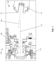
- FIG. 1 is an illustration of an example motor 102 and a gearbox 104 that are misaligned.
- the motor 102 includes a motor armature shaft 106.
- the motor armature shaft 106 is a separable motor armature shaft that further includes internal motor splines 112.
- a first alignment axis 110 extends from a center point of the motor armature shaft 106 outwards, illustrating an axis for alignment of the motor 102 and the gearbox 104.
- the example motor 102 includes internal motor splines 112 and there is no external protrusion of the motor armature shaft 106 for alignment with the gearbox 104.
- the gearbox 104 includes a gearbox shaft 107 and internal gearbox splines 114. Similarly to the motor 102, the gearbox 104 does not include an external protrusion to facilitate alignment.
- the example first alignment axis 110 of the motor 102 and a second alignment axis 108 of the gearbox 104 are not parallel when initially installed due to machining tolerances, surrounding mount hardware, etc. Therefore, the motor 102 and the gearbox 104 are not in alignment. However, the gearbox 104 and the motor 102 should be aligned for effective operation. As will be described in association with FIG. 2 , disclosed examples provide alignment tools that can be used to align the motor 102 and the gearbox 104.
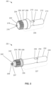
- FIG. 2 is an illustration of an example gearbox alignment tool 202 and a motor alignment tool 222.
- the gearbox alignment tool 202 includes at least four components: a first tubular body 205 (e.g., a first cylindrical body), a first plug 204, a first threaded nut 220, and a first cap screw 218.
- a first component of the example gearbox alignment tool 202 is the first tubular body 205.
- the first tubular body 205 is an elongated member that is generally tubular (e.g., cylindrical) in shape with a hole (as will be described in association with FIG. 4 ) extending from a first end 213 of the first tubular body 205 to a second end 206 of the first tubular body 205.
- the hole may be a counterbore hole (as will be described in association with FIG. 4 ) to allow a screw (e.g., a socket head cap screw) to sit flush with an outer surface of the first tubular body 205.
- the first tubular body 205 includes a first shaft 212, a first shoulder 208, and a first neck 207.
- the example first shaft 212 includes a first flat member 210 and a second flat member 214.
- the first flat member 210 and the second flat member 214 provide flat surfaces that can be gripped by a wrench or any other tool.
- the first shaft 212 is coupled to the first shoulder 208 that extends radially outward such the first shoulder 208 bears against an edge of the motor armature shaft 106, locking the first shaft 212 in place. Accordingly, the first shoulder 208 is of greater diameter than the first shaft 212 and the first neck 207.
- the example first shoulder 208 is coupled to the first neck 207.
- the first tubular body 205, and more particularly the first neck 207 includes radial sharp ridges at the second end 206 of the first tubular body 205 that extend towards the first plug 204 and retain the first plug 204.
- the ridges of the first neck 207 will be illustrated in further detail in FIG. 3 .
- a second component of the example gearbox alignment tool 202 is the first plug 204.
- the first plug 204 is coupled to the first shoulder 208 at a first plug edge and coupled to the first threaded nut 220 at a second plug edge.
- the first plug 204 is an elastomeric plug such as a urethane plug, a rubber plug, etc.
- the first plug 204 also includes a hole through the first plug 204, a diameter of the hole based on a diameter of the first cap screw 218.
- a third example component of the gearbox alignment tool 202 is the first threaded nut 220.
- the first threaded nut 220 may be any type of fastener.
- the fastener e.g., the first threaded nut 220
- examples disclosed herein are not limited to a threading to couple the first and second fasteners.
- the first fastener may be welded to the second fastener, the first fastener to generate an axial force along an axis defined by the second fastener.
- the first and second fasteners may be a single, unitary force-generating member.
- the first threaded nut 220 includes second ridges (as will be described in association with FIG. 3 ) extending radially towards the first end 213 and includes second protrusions to couple the first threaded nut 220 to the first plug 204.
- the first threaded nut 220 is a fastener that includes a first threaded hole 216 with threads to couple the first threaded nut 220 to the first cap screw 218.
- a fourth component of the example gearbox alignment tool 202 is the first cap screw 218.
- the first cap screw 218 may be any type of fastener that may couple (e.g., threadably couple) to another fastener.
- the first cap screw 218 extends through the first tubular body 205, the first plug 204, and the first threaded nut 220.
- the first cap screw 218 may include threads at a first threaded end of the first cap screw 218.
- the first cap screw 218 includes, for example, a socket head that can be adjusted by a hex key, an Allen wrench, and/or any other torquing device.
- the first cap screw 218 has a socket head.
- any type of screw e.g., square head, one-way head, slotted head, torx head, etc.
- examples disclosed herein are not limited to a cap screw, a socket head cap screw, or any screw in general: any type of device to generate an axial force on the plug can be used. This extends not only to mechanical fasteners such as bolts (e.g., a hex-head bolt, any threaded or unthreaded bolt), but to methods such as pressurized fluid cylinders that can generate an axial force.
- screw threads facilitate generation of an axial force by a first fastening member.
- a fluid cylinder e.g., air cylinder, oil cylinder
- the example gearbox alignment tool 202 may be assembled by inserting a threaded end of the first cap screw 218 through the first end 213 towards the second end 206 of the first tubular body 205.
- the first cap screw 218 is of greater length than the first tubular body 205 (e.g., the first cylindrical body). Therefore, the first cap screw 218 protrudes from the second end 206 of the first tubular body 205 when the head of the first cap screw 218 is flush with the first end 213.
- the example first plug 204 may be fed onto the first cap screw 218 and coupled to the second end 206 of the first tubular body 205.
- the first threaded nut 220 may then be screwed onto threads of the first cap screw 218.
- the example gearbox alignment tool 202 is assembled and inserted into internal gearbox splines 114 of the gearbox 104 of FIG. 1 .
- the gearbox alignment tool 202 is inserted with the first threaded nut 220 in a first position that does not compress the first plug 204.
- the gearbox alignment tool 202 is advanced into the gearbox 104 until the first shoulder 208 contacts the gearbox shaft 107 of FIG. 1 .
- the first cap screw 218 is tightened, using another open-ended wrench on the machined flat, and more particularly, on the first flat member 210 to prevent rotation.
- the tightening of the first cap screw 218 causes the first threaded nut 220 to move to a second position towards the first tubular body 205, the second position nearer the first tubular body 205 than the first position.
- the example motor alignment tool 222 includes a second tubular body 227 (e.g., a second cylindrical body), a second plug 224, a second threaded nut 242, and a second cap screw 238.
- the second cap screw 238 may, in some instances, be a socket head cap screw. However, any type of device to generate an axial force on the second plug 224 may be used instead of a socket head cap screw.
- the second tubular body 227 (e.g., the second cylindrical body) is an elongated member that is generally tubular (e.g., cylindrical) in shape with a hole (as will be described in association with FIG. 4 ) extending from a third end 233 of the second tubular body 227 to a fourth end 236 of the second tubular body 227.
- the hole may be a counterbore hole (as will be described in association with FIG. 4 ) to allow a screw (e.g., a socket head cap screw) to sit flush with an outer surface of the second tubular body 227.
- the second tubular body 227 may be a unitary, integral, and/or one-piece construction that includes a second shaft 232, a second shoulder 228, and a second neck 235.
- the second shaft 232 includes a third flat member 230 and a fourth flat member 234.
- the second tubular body 227 may be a unitary (e.g., one-piece) construction or may include multiple parts that are welded and/or otherwise coupled together.
- the first tubular body 205 may be a one-piece member while the second tubular body 227 is a multi-piece member with at least one weld.
- the example second shoulder 228 is a protrusion having greater diameter than the second shaft 232 and the second neck 235.
- the second shoulder 228 is coupled to the second neck 235.
- the second shoulder 228 is of a different diameter than the first shoulder 208, as the example motor armature shaft 106 and the gearbox shaft 107 are different sizes.
- the second plug 224 is coupled to the second shoulder 228 at a third plug edge and coupled to the second threaded nut 242 at a fourth plug edge.
- the second plug 224 also includes a hole through the second plug 224 to accommodate the second cap screw 238.
- the second cap screw 238 may be any type of fastener (e.g., a second socket head cap screw) that may couple (e.g., threadably couple) to a second fastener.
- the motor armature shaft 106 of FIG. 1 may be made of a different material than the gearbox shaft 107 of FIG. 1 .
- the second plug 224 may be comprised of a different materials than the first plug 204 to prevent damage to its respective component.
- the second threaded nut 242 includes fourth protrusions to couple the second threaded nut 242 to the second plug 224.
- the second threaded nut 242 may be any type of fastener that may couple (e.g., threadably couple) to a second fastener.
- the second threaded nut 242 includes a second threaded hole 240 with threads to couple the second threaded nut 242 to the second cap screw 238.
- the second cap screw 238 (e.g., or any fastener of appropriate length) extends through the second tubular body 227, the second plug 224, and the second threaded nut 242.
- the second cap screw 238 may include threads at a first threaded end 237 of the second cap screw 238.
- the second cap screw 238 includes a socket head that can be adjusted by any matching torquing device such as a standard wrench, screwdriver, socket wrench, Allen wrench, etc.
- the example motor alignment tool 222 is assembled and inserted into internal motor splines of the example motor 102 of FIG. 1 until the second shoulder 228 contacts the end of the motor armature shaft 106 of FIG. 1 (e.g., in order to assure the second shaft 232 is colinear with the motor armature shaft 106).
- the second cap screw 238 is tightened, expanding the example second plug 224 and securing the example motor alignment tool 222 into position.
- the example motor alignment tool 222 shares geometric characteristics with the gearbox alignment tool 202. However, when compared to the gearbox alignment tool 202, the motor alignment tool 222 includes resized and/or reshaped analogues of members of the gearbox alignment tool 202. The differences in shape between the gearbox alignment tool 202 and the motor alignment tool 222 are based on respective geometric characteristics of the gearbox 104 of FIG. 1 and the motor 102 of FIG. 1 .
- FIG. 3 is another illustration of the example motor alignment tool 222. Although the structure and function of the second plug 224 is described in association with FIG. 3 , the gearbox alignment tool 202 of FIG. 2 and the first plug 204 of FIG. 2 share functionalities described in association with FIG. 3 .
- FIG. 3 includes the example motor alignment tool 222, first ridges 303, a first beveled edge 304, second ridges 307, first protrusions 308, a second beveled edge 310, first threads 312, and a third beveled edge 316.
- a material for the first plug 204 and the second plug 224 is selected based on the materials modulus of elasticity and/or a desired Poisson ratio.
- Example materials with suitable Poisson's ratios include urethanes and polymers (fluoropolymer elastomers, ethylene propylene diene monomer, nitrile rubber, etc.). Using "soft" materials such as this also has the added benefit of reducing and/or preventing potential damage to the female shaft contours into which the tool is inserted.
- one or more alignment tools as described herein may be used for alignment of a driver component (e.g., a prime mover) and a driven component.
- the driver component may be an electric motor, a fluidic motor (e.g., air, hydraulic, etc.), a diesel engine, a gasoline engine, a steam engine, a steam turbine, a gas turbine, a windmill, etc.
- the driven component may be a stationary component such as a pump, a compressor, a generator, a fan, a milling machine, a rolling mill, a lathe, etc.
- the driven component may be a mobile component such as an automobile (e.g., a car, a truck, etc.), an aviation propeller, a marine propeller, a locomotive, etc.
- the driver component and the driven component may be connected by a gearbox or a transmission, for example.
- the alignment tools described herein may be used for alignment of any combination of the driver component and the driven components listed above.
- a diesel engine may be coupled to a generator
- a steam engine may be coupled to a ship's propeller
- a hydraulic fluidic motor may be coupled to a milling machine, etc.
- the driver component and the driven component can be aligned using the alignment tools described herein.
- the elastomeric plug(s) described herein can be repurposed as robotic gripper(s) that grip an object in the center hole (e.g., based on the Poisson effect) when the elastomeric plug(s) is/are axially compressed.
- the second plug 224 does not damage the internal motor splines 112 upon expansion, as the second plug 224 makes a soft compressive contact with the internal motor splines 112 of FIG. 2 .
- the second cap screw 238 applies pressure to the second plug 224.
- the second plug 224 is urethane or another elastomer, the second plug 224 does not cause a metal-to-metal load that could damage the motor armature shaft 106 of FIG. 1 .
- the second plug 224 causes a firm contact between the soft, rubbery second plug 224 and the motor armature shaft 106.
- FIG. 3 illustrates additional characteristics of the example motor alignment tool 222.
- the motor alignment tool 222 includes the first ridges 303 of the second neck 235.
- the first ridges 303 are sharp ridges and/or teeth that press into the second plug 224, securing the second plug 224 to the second neck 235.
- the example second threaded nut 242 includes the second ridges 307.
- the second ridges 307 are sharp ridges and/or teeth that press into the second plug 224, securing the second plug 224 to the second nut 242 and reducing rotation.
- the first threads 312 rotate.
- the second shaft 232 and the second neck do not rotate, however.
- the first ridges 303 protrude into the second plug 224 the second plug 224 does not rotate with the second cap screw 238.
- the second threaded nut 242 is coupled to the second plug 224 by the second ridges 307 and therefore does not rotate with the second cap screw 238.
- the second nut 242 is displaced in the direction of the third arrow 314, causing the second plug 224 to expand and exhibit the Poisson effect.
- the example second plug 224 includes the first beveled edge 304 and the second beveled edge 310.
- the first and second beveled edges 304 and 310 facilitate insertion of the motor alignment tool 222 into the motor 102 of FIG. 1 .
- the second threaded nut 242 includes the third beveled edge 316 to facilitate insertion of the tool into the motor 102 of FIG. 1 . (e.g., by self-centering).
- First protrusions 308 mate with the female splines in the motor 102 of FIG. 1 , further securing the motor alignment tool 222 to the motor 102 of FIG. 1 .
- FIG. 4 is a cross-sectional view of the example gearbox alignment tool 202 inserted into the gearbox 104 and the motor alignment tool 222 inserted into the motor 102.
- the example gearbox alignment tool 202 further includes a first axial hole 410 and a first counterbore 406.
- the first axial hole 410 extends through the first tubular body 205.
- the first counterbore 406 is a cylindrical flat-bottomed hole extending partially within the first tubular body 205, that is coaxial with, and of greater diameter than, the first axial hole 410.
- the first cap screw 218 includes a first socket head 402 that is of greater diameter than the first axial hole 410 and of a lesser diameter than the first counterbore 406.
- the first counterbore 406 allows the first cap screw 218 to sit flush with an outer face of the gearbox alignment tool 202.
- the example first socket head 402 is rotated by a hex key and/or any other adjustment device to cause the first threaded nut 220 to compress the first plug 204 and cause the first plug 204 to expand, as previously described.
- the example motor alignment tool 222 includes a second axial hole 412 and a second counterbore 408.
- the second axial hole 412 extends through the second tubular body 227.
- the second counterbore 408 is a cylindrical flat-bottomed hole extending partially within the second tubular body 227, that is coaxial with, and of greater diameter than, the second axial hole 412.
- the second counterbore 408 allows the second cap screw 238 to sit flush with an outer face of the motor alignment tool 222.
- An example second socket head 404 is rotated to compress the second plug 224 and cause the second plug 224 to expand.
- the counterbore feature and use of a socket-head cap screw, such as first cap screw 218 and second cap screw 238, inside the shafts 212 and 232 of the first tubular body 205 and 227, respectively, may be optional in some examples.
- Other methods for compressing the plugs 204 and 224 can be used.
- an air or hydraulically operated cylinder and rod can also be used to compress the plugs 204, 224.
- FIG. 5A is an example first illustration 502 that shows alignment of the example motor 102 with the gearbox 104.
- a first illustration 502 includes the gearbox alignment tool 202 and the motor alignment tool 222 that are out of alignment.
- FIG. 5B is an example second illustration 504 that includes a dial indicator 500 that can be used to facilitate alignment of the motor 102 and the gearbox 104 based on the example motor alignment tool 222 and the example gearbox alignment tool 202.
- the example dial indicator 500 determines whether the motor alignment tool 222 and the gearbox alignment tool 202 are properly aligned. Based on a reading of the dial indicator 500, the motor 102 and/or the gearbox 104 can be moved and rotated to facilitate parallel and angular alignment.
- FIG. 6A is a third illustration 602 in which the motor 102 and the gearbox 104 are in parallel and angular alignment, as illustrated by a shaft alignment axis 608.
- at least one of the example gearbox 104 or the motor 102 is pinned into position, allowing removal of the other of the motor 102 and/or the gearbox 104.
- FIG. 6B is a fourth illustration 604 that shows a shaft 610 installed and in proper alignment. After the motor 102 and/or the gearbox 104 are removed, the example shaft 610 is inserted. The motor 102 and/or the gearbox 104 is then re-positioned based on the prior pinning. The shaft 610 is installed in an aligned motor-driven propeller to connect the motor 102 and the gearbox 104.
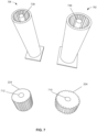
- FIG. 7 illustrates example molds for casting the first plug 204 and second plug 224 as described herein.
- a first mold 702 is a mold that can cast the first plug 204.
- a second mold 704 is a second mold that can cast the second plug 224.
- the first mold 702 and the second mold 704 are three-dimensional molds that include contours of each respective plug. To accurately form the plugs 204, 224, the first mold 702 and the second mold 704 replicate the internal splines of the motor armature shaft 106 of FIG. 1 and the gearbox shaft 107 of FIG. 1 , respectively.
- the first mold 702 includes a first cylindrical member 706 to form a first hole 710 in the first plug 204.
- the second mold 704 includes a second cylindrical member 708 to form a second hole 712 in the second plug 224.
- the first hole 710 and/or the second hole 712 may accommodate a compression-generating component such as a cap screw, bolt, or hydraulic/air cylinder shaft. More particularly, the hole 710 in first plug 204 accommodates the first cap screw 218 ( FIG. 2 ) and the hole 712 in the second plug 224 accommodates the second cap screw 238 ( FIG. 2 ).
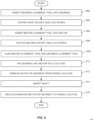
- FIG. 8 is a flowchart illustrating an example method to align a motor-driven propeller.
- the example method begins at block 800 at which the gearbox alignment tool 202 of FIG. 2 is inserted into the gearbox 104 of FIG. 1 .
- the first cap screw 218 of FIG. 2 is tightened. For instance, tightening of the first cap screw 218 causes the first plug 204 of FIG. 2 to expand and secure the gearbox alignment tool 202 of FIG. 2 .
- the example motor alignment tool 222 of FIG. 2 is inserted into the motor 102 of FIG. 1 .
- the second cap screw 238 of FIG. 2 is tightened. For instance, tightening the second cap screw 238 of FIG. 2 causes the second plug 224 to expand and secure the motor alignment tool 222 of FIG. 2 to the motor 102 of FIG. 1 .
- the example motor alignment tool 222 of FIG. 2 and the gearbox alignment tool 202 of FIG. 2 are aligned.
- the gearbox alignment tool 202 and the example motor alignment tool 222 of FIG. 2 can be aligned using dial indicator 500 of FIG. 5B .
- the example gearbox 104 of FIG. 1 and/or the motor 102 of FIG. 2 are pinned into location.
- the motor 102 of FIG. 2 can be pinned into location before removing the gearbox 104 of FIG. 1 at block 812.
- the example drive shaft 610 of FIG. 6B is placed in the motor 102 of FIG. 1 or the gearbox 104 of FIG. 1 bef76ore replacing the motor 102 of FIG. 1 or the example gearbox 104 of FIG. 1 at block 816.
- example systems, apparatus, and articles of manufacture have been disclosed that enable alignment of a motor-driven propeller.
- Examples disclosed herein include an example gearbox alignment tool and an example motor alignment tool.
- Disclosed examples facilitate effective alignment of internally splined shafts. Proper alignment of the shafts reduces stress on the rotating machinery, improving part lifespan and machinery safety.
- An apparatus comprising a tubular body including a shaft, a shoulder, and a neck, the shaft coupled to the shoulder, the shoulder coupled to the neck, the shoulder having a greater diameter than respective diameters of the shaft and the neck, a plug coupled to the shoulder at a first plug edge and coupled to a first fastener at a second plug edge, the first fastener including a hole, and a second fastener coupled to the first fastener, the second fastener extending through the tubular body, the plug, and the first fastener.
- the first fastener is a threaded nut
- the second fastener is a cap screw
- the tubular body, the plug, the threaded nut, and the cap screw define a motor alignment tool, the motor alignment tool coupled to a motor, the shaft extending from the motor to facilitate alignment of the motor.
- tubular body is a first tubular body
- the plug is a first plug
- the threaded nut is a first threaded nut
- the cap screw is a first cap screw
- gearbox alignment tool to facilitate an alignment of a gearbox with the motor, the gearbox alignment tool including a second tubular body, a second plug, a second threaded nut, and a second cap screw.
- An alignment apparatus for a motor-driven propeller comprising a motor tool coupled to a motor of the motor-driven propeller, the motor tool extending from the motor to facilitate an alignment of the motor-driven propeller, a gearbox tool coupled to a gearbox of the motor-driven propeller and extending from the gearbox to facilitate the alignment, and at least one of the gearbox tool or the motor tool including a tubular body including a shaft, a shoulder, and a neck, the shaft coupled to the shoulder, the shoulder coupled to the neck, a plug coupled to the shoulder at a first plug edge and coupled to a first fastener at a second plug edge, the first fastener including a hole, and a second fastener extending through the tubular body, the plug, and the first fastener.
- the first fastener is a cap screw that further includes threads at a first end of the cap screw, and a socket head at a second end of the cap screw.
- first plug edge and the second plug edge are beveled, and wherein the plug includes at least one protrusion that extends radially outward.
- tubular body is a one-piece body.
- a method comprising inserting a gearbox alignment tool into a gearbox, tightening a first fastener of the gearbox alignment tool, inserting a motor alignment tool into a motor, tightening a second fastener of the motor alignment tool, and aligning the motor and the gearbox based on the motor alignment tool and gearbox alignment tool.
- An alignment apparatus comprising at least one of a first alignment tool or a second alignment tool, the first alignment tool coupled to a driver component, the first alignment tool extending from the driver to facilitate an alignment, the second alignment tool coupled to a driven component and extending from the driven component to facilitate the alignment, and at least one of the first alignment tool or the second alignment tool including a tubular body including a shaft, a shoulder, and a neck, the shaft coupled to the shoulder, the shoulder coupled to the neck, a plug coupled to the shoulder at a first plug edge and coupled to a first fastener at a second plug edge, the first fastener including a hole, and a second fastener extending through the tubular body, the plug, and the first fastener.
- the first fastener is a threaded nut
- the second fastener is a cap screw
- to tighten the cap screw causes a displacement of the threaded nut from a first position to a second position, wherein the second position is nearer the tubular body
- the displacement of the threaded nut causes the plug to increase in diameter to contact at least one of the driver component or the driven component.
- the driver component is a motor and the driven component is a pump, a compressor, a generator, a fan, a milling machine, a rolling mill, or a lathe.
- driver component is a motor and the driven component is an automobile, a truck, a propeller, or a locomotive.
- driver component is an engine and the driven component is a pump, a compressor, a generator, a fan, a milling machine, a rolling mill, or a lathe.
- driver component is an engine and the driven component is an automobile, a truck, a propeller, or a locomotive.
- driver component is a turbine and the driven component is a pump, a compressor, a generator, a fan, a milling machine, a rolling mill, or a lathe.
- driver component is a turbine and the driven component is an automobile, a truck, a propeller, or a locomotive.
- the driver component is a windmill and the driven component is a pump, a compressor, a generator, a fan, a milling machine, a rolling mill, a lathe, an automobile, a truck, a propeller, or a locomotive.
- the tubular body including first ridges protruding into the plug and towards the first fastener, the first fastener including second ridges protruding into the plug and towards the tubular body.
- a first end of the tubular body includes a second hole that extend through the shaft, the shoulder, and the neck to a second end of the tubular body.
- the first fastener is a cap screw that further includes threads at a first end of the cap screw, and a socket head at a second end of the cap screw.
- first plug edge and the second plug edge are beveled, and wherein the plug includes at least one protrusion that extends radially outward.
- tubular body is a one-piece body.
Landscapes
- Engineering & Computer Science (AREA)
- General Engineering & Computer Science (AREA)
- Mechanical Engineering (AREA)
- Power Engineering (AREA)
- Manufacturing & Machinery (AREA)
- Chemical & Material Sciences (AREA)
- Combustion & Propulsion (AREA)
- Connection Of Motors, Electrical Generators, Mechanical Devices, And The Like (AREA)
Claims (13)
- Vorrichtung (202, 222) zum Ausrichten einer antreibenden und einer angetriebenen Komponente, umfassend:einen röhrenförmigen Körper (205, 227), der einen Schaft (212, 232), eine Schulter (208, 228) und einen Hals (207, 235) einschließt, wobei der Schaft (212, 232) mit der Schulter (208, 228) gekoppelt ist, die Schulter (208, 228) mit dem Hals (207, 235) gekoppelt ist, wobei die Schulter (208, 228) einen größeren Durchmesser als jeweilige Durchmesser des Schafts (212, 232) und des Halses (207, 235) aufweist;einen Stopfen (204, 224), der an einer ersten Stopfenkante (304) mit dem Hals (207, 235) gekoppelt ist und an einer zweiten Stopfenkante (310) mit einem ersten Befestigungselement (220, 242) gekoppelt ist, wobei das erste Befestigungselement (220, 242) ein Loch (216, 240) einschließt; undein zweites Befestigungselement (218, 238), das mit dem ersten Befestigungselement (220, 242) gekoppelt ist, wobei das zweite Befestigungselement (218, 238) sich durch den röhrenförmigen Körper (205, 227), den Stopfen (204, 224) und das erste Befestigungselement (220, 242) erstreckt.
- Vorrichtung nach Anspruch 1, wobei das erste Befestigungselement (242) eine Gewindemutter (242) ist, das zweite Befestigungselement (238) eine Kopfschraube (238) ist und wobei der röhrenförmige Körper (227), der Stopfen (224), die Gewindemutter (242) und die Kopfschraube (238) ein Motorausrichtungswerkzeug (222) definieren, wobei das Motorausrichtungswerkzeug (222) mit einem Motor (102) gekoppelt ist, wobei die Welle (232) sich von dem Motor (102) erstreckt, um die Ausrichtung des Motors (102) zu fördern.
- Vorrichtung nach Anspruch 2, wobei der röhrenförmige Körper (227) ein zweiter röhrenförmiger Körper (227) ist, der Stopfen (224) ein zweiter Stopfen (224) ist, die Gewindemutter (242) eine zweite Gewindemutter (242) ist, die Kopfschraube (238) eine zweite Kopfschraube (238) ist, und die ferner ein Getriebeausrichtungswerkzeug (202) einschließt, um eine Ausrichtung eines Getriebes (104) mit dem Motor (102) zu fördern, wobei das Getriebeausrichtungswerkzeug (202) einen ersten röhrenförmigen Körper (205), einen ersten Stopfen (204), eine erste Gewindemutter (220) und eine erste Kopfschraube (218) einschließt.
- Vorrichtung nach Anspruch 3, wobei ein Anziehen der ersten Kopfschraube (218) eine axiale Verschiebung (314) der ersten Gewindemutter (220) von einer ersten Position in eine zweite Position bewirkt, wobei die zweite Position näher an dem ersten röhrenförmigen Körper (205) als die erste Position liegt, und wobei ein Durchmesser des ersten Stopfens (204) sich vergrößert, um als Reaktion auf die axiale Verschiebung (314) das Getriebe (104) zu berühren.
- Vorrichtung nach einem der Ansprüche 2 bis 4, wobei der röhrenförmige Körper (227) erste Rippen (303) einschließt, die in den Stopfen (224) und in Richtung der Gewindemutter (242) hineinragen.
- Vorrichtung nach Anspruch 5, wobei die Gewindemutter (242) zweite Rippen (307) einschließt, die in den Stopfen (224) und in Richtung des röhrenförmigen Körpers (227) hineinragen, wobei die Gewindemutter (242) durch ein Gewinde mit der Kopfschraube (238) gekoppelt ist.
- Vorrichtung nach einem der Ansprüche 2 bis 6, wobei ein erstes Ende des röhrenförmigen Körpers (227) ein zweites Loch (412) mit einer Senkbohrung (408) einschließt, wobei das zweite Loch (412) sich durch den Schaft (232), die Schulter (228) und den Hals (235) zu einem zweiten Ende (236) des röhrenförmigen Körpers (227) erstreckt.
- Vorrichtung nach Anspruch 3 oder einem von Anspruch 3 abhängigen Anspruch, wobei die erste Kopfschraube (218) ferner Gewinde (312) an einem ersten Ende der ersten Kopfschraube (218) einschließt.
- Vorrichtung nach Anspruch 8, wobei die erste Kopfschraube (218) ferner einen Innensechskantkopf (402) an einem zweiten Ende der ersten Kopfschraube (218) einschließt.
- Vorrichtung nach einem der vorstehenden Ansprüche, wobei die erste Steckkante (304) und die zweite Steckkante (310) abgeschrägt sind.
- Vorrichtung nach Anspruch 10, wobei der Stopfen (204, 224) mindestens einen Vorsprung (308) einschließt, der sich radial nach außen erstreckt.
- Vorrichtung nach Anspruch 11, wobei der röhrenförmige Körper (205, 227) ein einheitlicher, einteiliger Körper ist.
- Verfahren, umfassend:Bereitstellen der Einrichtung nach Anspruch 3;Einsetzen des Getriebeausrichtungswerkzeugs (202) in ein Getriebe (104);Anziehen der ersten Gewindemutter (220) des Getriebeausrichtungswerkzeugs (202);Einsetzen des Motorausrichtungswerkzeugs (222) in einen Motor (102);Anziehen der zweiten Kopfschraube (238) des Ausrichtungswerkzeugs (222) des Motors (102);Ausrichten des Motors (102) und des Getriebes (104) basierend auf dem Motorausrichtungswerkzeug (222) und dem Getriebeausrichtungswerkzeug (202);Befestigen des Getriebes (104) und des Motors (102) in einer ausgerichteten Position;Entfernen des Getriebes (104) oder des Motors von der ausgerichteten Position;Einsetzen einer Welle (610); undWiedereinsetzen des Motors (102) oder des Getriebes (104) an der ausgerichteten Position.
Applications Claiming Priority (1)
| Application Number | Priority Date | Filing Date | Title |
|---|---|---|---|
| US17/900,524 US12188366B2 (en) | 2022-08-31 | 2022-08-31 | Alignment tool |
Publications (2)
| Publication Number | Publication Date |
|---|---|
| EP4332401A1 EP4332401A1 (de) | 2024-03-06 |
| EP4332401B1 true EP4332401B1 (de) | 2025-06-25 |
Family
ID=86425946
Family Applications (1)
| Application Number | Title | Priority Date | Filing Date |
|---|---|---|---|
| EP23174179.4A Active EP4332401B1 (de) | 2022-08-31 | 2023-05-18 | Ausrichtungswerkzeug |
Country Status (3)
| Country | Link |
|---|---|
| US (1) | US12188366B2 (de) |
| EP (1) | EP4332401B1 (de) |
| CN (1) | CN117639399A (de) |
Family Cites Families (27)
| Publication number | Priority date | Publication date | Assignee | Title |
|---|---|---|---|---|
| US3525158A (en) * | 1967-07-31 | 1970-08-25 | United States Steel Corp | Apparatus for aligning shafts and the like |
| DE4005708A1 (de) | 1990-02-23 | 1991-08-29 | Jakob Ludwig | Bewegliche kupplung in schalenbauweise |
| US5479718A (en) * | 1994-07-19 | 1996-01-02 | Durametallic Corporation | Shaft alignment device |
| US5806161A (en) | 1995-11-16 | 1998-09-15 | Schneider; Danniel Shane | Shaft spline alignment tool |
| US5860864A (en) | 1997-01-10 | 1999-01-19 | Camco International, Inc. | Joint assembly having self-biasing mechanism to bias two shafts into coaxial alignment |
| US5843201A (en) * | 1997-11-06 | 1998-12-01 | Emhart Glass Machinery Investments Inc. | Invert and neck ring holder mechanism for an I.S. machine |
| US5846282A (en) * | 1997-11-06 | 1998-12-08 | Emhart Glass Machinery Investments Inc. | Invert and neck ring holder mechanism for an I.S. machine |
| US7765082B2 (en) | 2000-09-11 | 2010-07-27 | Axiam, Incorporated | System for optimal alignment of a shaft of a gas turbine |
| US6883224B2 (en) | 2002-02-01 | 2005-04-26 | Honeywell International Inc. | Gas turbine impeller alignment tool and method |
| JP4452053B2 (ja) * | 2003-10-01 | 2010-04-21 | 三菱重工業株式会社 | 軸ずれ測定装置 |
| US7658242B2 (en) * | 2006-01-17 | 2010-02-09 | Duncan C Warren | Hole coring system with lever arm |
| DE102008010916A1 (de) * | 2008-02-25 | 2009-08-27 | Prüftechnik Dieter Busch AG | Verfahren und Vorrichtung zur Ermittlung einer Ausrichtung von zwei drehbar gelagerten Maschinenteilen, einer Ausrichtung von zwei hohlzylinderförmigen Maschinenteilen oder zur Prüfung einer Komponente auf Geradheit entlang einer Längsseite |
| SE532983C2 (sv) * | 2008-10-10 | 2010-06-01 | Elos Fixturlaser Ab | Anordning och metod för uppmätning och inriktning av en första komponent och en andra komponent i förhållande till varandra |
| JP2010137766A (ja) | 2008-12-12 | 2010-06-24 | Ntn Corp | 車輪用軸受装置のための接合方法及び接合用治具 |
| US8955230B2 (en) * | 2012-06-12 | 2015-02-17 | Solar Turbines Inc. | Shaft alignment tools and methods |
| US8997365B2 (en) | 2012-06-12 | 2015-04-07 | Solar Turbines Incorporated | Shaft alignment tools and methods |
| WO2014051663A1 (en) | 2012-09-28 | 2014-04-03 | United Technologies Corporation | Alignment tool for use in a gas turbine engine |
| DE102012022487A1 (de) * | 2012-11-19 | 2014-05-22 | Prüftechnik Dieter Busch AG | Vorrichtung und Verfahren zum Ermitteln der Lage zweier gekuppelter Wellen zueinander |
| US9421003B2 (en) * | 2013-02-18 | 2016-08-23 | Covidien Lp | Apparatus for endoscopic procedures |
| DE102015110089A1 (de) * | 2014-06-27 | 2015-12-31 | Magna Closures Inc. | Elektromechanische Strebe mit integrierter Flexkupplung und Schlupfvorrichtung und zugehörige Kupplungs-/Kopplungs-Anordnung |
| US9695878B2 (en) | 2015-07-09 | 2017-07-04 | Ford Global Technologies, Llc | Plug-in propshaft assembly tool |
| WO2018055427A1 (en) | 2016-09-20 | 2018-03-29 | Carrier Corporation | Tool for use with a belted sheave system and method of use |
| US20220056958A1 (en) | 2018-09-21 | 2022-02-24 | Schaeffler Technologies AG & Co. KG | Torque transmission member and centering tool for centering assembly of torque transmission member |
| US11300404B2 (en) * | 2018-10-21 | 2022-04-12 | Shoreline Alignment & Vibration, LLC | Alignment of rotational shafts |
| US11975825B2 (en) | 2020-11-23 | 2024-05-07 | Textron Innovations Inc. | Spline with expendable spherical alignment head |
| US12195121B2 (en) | 2020-12-11 | 2025-01-14 | Solar Turbines Incorporated | Transportation trailer and machinery coupling alignment system |
| CN113007321B (zh) * | 2021-02-23 | 2023-07-07 | 精进电动科技股份有限公司 | 阶梯销定位的电驱动动力传动系统箱体总成及其安装方法 |
-
2022
- 2022-08-31 US US17/900,524 patent/US12188366B2/en active Active
-
2023
- 2023-05-18 EP EP23174179.4A patent/EP4332401B1/de active Active
- 2023-07-11 CN CN202310845074.4A patent/CN117639399A/zh active Pending
Also Published As
| Publication number | Publication date |
|---|---|
| US20240068383A1 (en) | 2024-02-29 |
| US12188366B2 (en) | 2025-01-07 |
| EP4332401A1 (de) | 2024-03-06 |
| CN117639399A (zh) | 2024-03-01 |
Similar Documents
| Publication | Publication Date | Title |
|---|---|---|
| EP3770407B1 (de) | Aufhängungdichtung eines gasturbinenmotors | |
| US20220243758A1 (en) | Combination nut assembly capable of preventing loosening thereof | |
| US20150044043A1 (en) | Attachment device for non-permanently attaching a child component to a parent component | |
| EP3002220A1 (de) | Montageanordnung für einen gasturbinenmotor | |
| US20150354616A1 (en) | Casing assembly | |
| CN113187797A (zh) | 一种用于输电线路杆塔及电力金具的可靠防松螺母 | |
| CN114029901A (zh) | 航空发动机燃气发生器转子装配工具以及装配方法 | |
| US12188366B2 (en) | Alignment tool | |
| CA3011573A1 (en) | Plunger clamp for fluid end | |
| GB2464182A (en) | Spline couplings having a rotational pre-load | |
| US3434747A (en) | Quickly operable keyless couplings | |
| US10040176B2 (en) | Extended impact socket construction | |
| WO1988002074A1 (en) | Bolted coupling | |
| CN108375444B (zh) | 一种自锁螺母锁紧力矩测量方法 | |
| GB2181511A (en) | Expansion bolt for bolted couplings | |
| US10307895B2 (en) | Extended impact socket construction | |
| US20210023927A1 (en) | System and method for gas turbine engine mount with seal | |
| CN110744486A (zh) | 柴油机曲轴减震器的拆装工具及拆装方法 | |
| US5256014A (en) | Nut threaded fastener for applying a predetermined preload | |
| RU2239731C2 (ru) | Легкосъемное крепежное соединение с радиальным натягом | |
| US7331873B2 (en) | Over-torque break away rotational coupling and a method of assembling same | |
| US20160333919A1 (en) | Method and system for installing keylock insert | |
| RU2519996C1 (ru) | Легкосъемное беззазорное крепежное соединение фланцев | |
| US11486448B2 (en) | Hub and secondary driving element shaft locking system | |
| CN121676145A (zh) | 一种用于涡轮发动机的防拆锁定组件 |
Legal Events
| Date | Code | Title | Description |
|---|---|---|---|
| PUAI | Public reference made under article 153(3) epc to a published international application that has entered the european phase |
Free format text: ORIGINAL CODE: 0009012 |
|
| STAA | Information on the status of an ep patent application or granted ep patent |
Free format text: STATUS: THE APPLICATION HAS BEEN PUBLISHED |
|
| AK | Designated contracting states |
Kind code of ref document: A1 Designated state(s): AL AT BE BG CH CY CZ DE DK EE ES FI FR GB GR HR HU IE IS IT LI LT LU LV MC ME MK MT NL NO PL PT RO RS SE SI SK SM TR |
|
| STAA | Information on the status of an ep patent application or granted ep patent |
Free format text: STATUS: REQUEST FOR EXAMINATION WAS MADE |
|
| 17P | Request for examination filed |
Effective date: 20240828 |
|
| RBV | Designated contracting states (corrected) |
Designated state(s): AL AT BE BG CH CY CZ DE DK EE ES FI FR GB GR HR HU IE IS IT LI LT LU LV MC ME MK MT NL NO PL PT RO RS SE SI SK SM TR |
|
| GRAP | Despatch of communication of intention to grant a patent |
Free format text: ORIGINAL CODE: EPIDOSNIGR1 |
|
| STAA | Information on the status of an ep patent application or granted ep patent |
Free format text: STATUS: GRANT OF PATENT IS INTENDED |
|
| RIC1 | Information provided on ipc code assigned before grant |
Ipc: F16D 1/10 20060101AFI20241129BHEP |
|
| INTG | Intention to grant announced |
Effective date: 20241212 |
|
| GRAS | Grant fee paid |
Free format text: ORIGINAL CODE: EPIDOSNIGR3 |
|
| RAP3 | Party data changed (applicant data changed or rights of an application transferred) |
Owner name: GENERAL ELECTRIC COMPANY |
|
| GRAA | (expected) grant |
Free format text: ORIGINAL CODE: 0009210 |
|
| STAA | Information on the status of an ep patent application or granted ep patent |
Free format text: STATUS: THE PATENT HAS BEEN GRANTED |
|
| P01 | Opt-out of the competence of the unified patent court (upc) registered |
Free format text: CASE NUMBER: APP_19121/2025 Effective date: 20250422 |
|
| AK | Designated contracting states |
Kind code of ref document: B1 Designated state(s): AL AT BE BG CH CY CZ DE DK EE ES FI FR GB GR HR HU IE IS IT LI LT LU LV MC ME MK MT NL NO PL PT RO RS SE SI SK SM TR |
|
| REG | Reference to a national code |
Ref country code: GB Ref legal event code: FG4D |
|
| REG | Reference to a national code |
Ref country code: CH Ref legal event code: EP |
|
| REG | Reference to a national code |
Ref country code: DE Ref legal event code: R096 Ref document number: 602023004217 Country of ref document: DE |
|
| REG | Reference to a national code |
Ref country code: CH Ref legal event code: EP |
|
| REG | Reference to a national code |
Ref country code: IE Ref legal event code: FG4D |
|
| PG25 | Lapsed in a contracting state [announced via postgrant information from national office to epo] |
Ref country code: FI Free format text: LAPSE BECAUSE OF FAILURE TO SUBMIT A TRANSLATION OF THE DESCRIPTION OR TO PAY THE FEE WITHIN THE PRESCRIBED TIME-LIMIT Effective date: 20250625 |
|
| REG | Reference to a national code |
Ref country code: LT Ref legal event code: MG9D |
|
| PG25 | Lapsed in a contracting state [announced via postgrant information from national office to epo] |
Ref country code: NO Free format text: LAPSE BECAUSE OF FAILURE TO SUBMIT A TRANSLATION OF THE DESCRIPTION OR TO PAY THE FEE WITHIN THE PRESCRIBED TIME-LIMIT Effective date: 20250925 Ref country code: GR Free format text: LAPSE BECAUSE OF FAILURE TO SUBMIT A TRANSLATION OF THE DESCRIPTION OR TO PAY THE FEE WITHIN THE PRESCRIBED TIME-LIMIT Effective date: 20250926 |
|
| PG25 | Lapsed in a contracting state [announced via postgrant information from national office to epo] |
Ref country code: BG Free format text: LAPSE BECAUSE OF FAILURE TO SUBMIT A TRANSLATION OF THE DESCRIPTION OR TO PAY THE FEE WITHIN THE PRESCRIBED TIME-LIMIT Effective date: 20250625 |
|
| PG25 | Lapsed in a contracting state [announced via postgrant information from national office to epo] |
Ref country code: HR Free format text: LAPSE BECAUSE OF FAILURE TO SUBMIT A TRANSLATION OF THE DESCRIPTION OR TO PAY THE FEE WITHIN THE PRESCRIBED TIME-LIMIT Effective date: 20250625 |
|
| PG25 | Lapsed in a contracting state [announced via postgrant information from national office to epo] |
Ref country code: RS Free format text: LAPSE BECAUSE OF FAILURE TO SUBMIT A TRANSLATION OF THE DESCRIPTION OR TO PAY THE FEE WITHIN THE PRESCRIBED TIME-LIMIT Effective date: 20250925 |
|
| PG25 | Lapsed in a contracting state [announced via postgrant information from national office to epo] |
Ref country code: LV Free format text: LAPSE BECAUSE OF FAILURE TO SUBMIT A TRANSLATION OF THE DESCRIPTION OR TO PAY THE FEE WITHIN THE PRESCRIBED TIME-LIMIT Effective date: 20250625 |
|
| REG | Reference to a national code |
Ref country code: NL Ref legal event code: MP Effective date: 20250625 |
|
| PG25 | Lapsed in a contracting state [announced via postgrant information from national office to epo] |
Ref country code: NL Free format text: LAPSE BECAUSE OF FAILURE TO SUBMIT A TRANSLATION OF THE DESCRIPTION OR TO PAY THE FEE WITHIN THE PRESCRIBED TIME-LIMIT Effective date: 20250625 |
|
| PG25 | Lapsed in a contracting state [announced via postgrant information from national office to epo] |
Ref country code: PT Free format text: LAPSE BECAUSE OF FAILURE TO SUBMIT A TRANSLATION OF THE DESCRIPTION OR TO PAY THE FEE WITHIN THE PRESCRIBED TIME-LIMIT Effective date: 20251027 |
|
| REG | Reference to a national code |
Ref country code: AT Ref legal event code: MK05 Ref document number: 1806707 Country of ref document: AT Kind code of ref document: T Effective date: 20250625 |
|
| PG25 | Lapsed in a contracting state [announced via postgrant information from national office to epo] |
Ref country code: IS Free format text: LAPSE BECAUSE OF FAILURE TO SUBMIT A TRANSLATION OF THE DESCRIPTION OR TO PAY THE FEE WITHIN THE PRESCRIBED TIME-LIMIT Effective date: 20251025 |
|
| PG25 | Lapsed in a contracting state [announced via postgrant information from national office to epo] |
Ref country code: AT Free format text: LAPSE BECAUSE OF FAILURE TO SUBMIT A TRANSLATION OF THE DESCRIPTION OR TO PAY THE FEE WITHIN THE PRESCRIBED TIME-LIMIT Effective date: 20250625 Ref country code: SM Free format text: LAPSE BECAUSE OF FAILURE TO SUBMIT A TRANSLATION OF THE DESCRIPTION OR TO PAY THE FEE WITHIN THE PRESCRIBED TIME-LIMIT Effective date: 20250625 |
|
| PG25 | Lapsed in a contracting state [announced via postgrant information from national office to epo] |
Ref country code: CZ Free format text: LAPSE BECAUSE OF FAILURE TO SUBMIT A TRANSLATION OF THE DESCRIPTION OR TO PAY THE FEE WITHIN THE PRESCRIBED TIME-LIMIT Effective date: 20250625 |
|
| PG25 | Lapsed in a contracting state [announced via postgrant information from national office to epo] |
Ref country code: PL Free format text: LAPSE BECAUSE OF FAILURE TO SUBMIT A TRANSLATION OF THE DESCRIPTION OR TO PAY THE FEE WITHIN THE PRESCRIBED TIME-LIMIT Effective date: 20250625 |
|
| PG25 | Lapsed in a contracting state [announced via postgrant information from national office to epo] |
Ref country code: EE Free format text: LAPSE BECAUSE OF FAILURE TO SUBMIT A TRANSLATION OF THE DESCRIPTION OR TO PAY THE FEE WITHIN THE PRESCRIBED TIME-LIMIT Effective date: 20250625 |
|
| PG25 | Lapsed in a contracting state [announced via postgrant information from national office to epo] |
Ref country code: SK Free format text: LAPSE BECAUSE OF FAILURE TO SUBMIT A TRANSLATION OF THE DESCRIPTION OR TO PAY THE FEE WITHIN THE PRESCRIBED TIME-LIMIT Effective date: 20250625 |
|
| PG25 | Lapsed in a contracting state [announced via postgrant information from national office to epo] |
Ref country code: ES Free format text: LAPSE BECAUSE OF FAILURE TO SUBMIT A TRANSLATION OF THE DESCRIPTION OR TO PAY THE FEE WITHIN THE PRESCRIBED TIME-LIMIT Effective date: 20250625 |
|
| PG25 | Lapsed in a contracting state [announced via postgrant information from national office to epo] |
Ref country code: DK Free format text: LAPSE BECAUSE OF FAILURE TO SUBMIT A TRANSLATION OF THE DESCRIPTION OR TO PAY THE FEE WITHIN THE PRESCRIBED TIME-LIMIT Effective date: 20250625 |
|
| PG25 | Lapsed in a contracting state [announced via postgrant information from national office to epo] |
Ref country code: IT Free format text: LAPSE BECAUSE OF FAILURE TO SUBMIT A TRANSLATION OF THE DESCRIPTION OR TO PAY THE FEE WITHIN THE PRESCRIBED TIME-LIMIT Effective date: 20250625 |
|
| PLBE | No opposition filed within time limit |
Free format text: ORIGINAL CODE: 0009261 |
|
| STAA | Information on the status of an ep patent application or granted ep patent |
Free format text: STATUS: NO OPPOSITION FILED WITHIN TIME LIMIT |
|
| REG | Reference to a national code |
Ref country code: CH Ref legal event code: L10 Free format text: ST27 STATUS EVENT CODE: U-0-0-L10-L00 (AS PROVIDED BY THE NATIONAL OFFICE) Effective date: 20260507 |