EP4332391B1 - Befestigungselement und verfahren zum befestigen - Google Patents
Befestigungselement und verfahren zum befestigen Download PDFInfo
- Publication number
- EP4332391B1 EP4332391B1 EP23193557.8A EP23193557A EP4332391B1 EP 4332391 B1 EP4332391 B1 EP 4332391B1 EP 23193557 A EP23193557 A EP 23193557A EP 4332391 B1 EP4332391 B1 EP 4332391B1
- Authority
- EP
- European Patent Office
- Prior art keywords
- workpiece
- fastening
- fastening element
- dowel sleeve
- shank
- Prior art date
- Legal status (The legal status is an assumption and is not a legal conclusion. Google has not performed a legal analysis and makes no representation as to the accuracy of the status listed.)
- Active
Links
Images

Classifications
-
- F—MECHANICAL ENGINEERING; LIGHTING; HEATING; WEAPONS; BLASTING
- F16—ENGINEERING ELEMENTS AND UNITS; GENERAL MEASURES FOR PRODUCING AND MAINTAINING EFFECTIVE FUNCTIONING OF MACHINES OR INSTALLATIONS; THERMAL INSULATION IN GENERAL
- F16B—DEVICES FOR FASTENING OR SECURING CONSTRUCTIONAL ELEMENTS OR MACHINE PARTS TOGETHER, e.g. NAILS, BOLTS, CIRCLIPS, CLAMPS, CLIPS OR WEDGES; JOINTS OR JOINTING
- F16B13/00—Dowels or other devices fastened in walls or the like by inserting them in holes made therein for that purpose
- F16B13/12—Separate metal or non-separate or non-metal dowel sleeves fastened by inserting the screw, nail or the like
- F16B13/124—Separate metal or non-separate or non-metal dowel sleeves fastened by inserting the screw, nail or the like fastened by inserting a threaded element, e.g. screw or bolt
Definitions
- the invention relates to a fastening element comprising a plastic dowel sleeve and an impact element for driving into the dowel sleeve, wherein the impact element expands the dowel sleeve at least partially in a radial direction when the impact element is driven into the dowel sleeve.
- the invention also relates to a method for fastening a workpiece to an object.
- EP 1 518 056 B1 discloses a plastic expansion anchor for expanding with an expansion nail.
- the invention is intended to improve a fastening element with a plastic dowel sleeve and an impact element for driving into the dowel sleeve as well as a method for fastening a workpiece to an object.
- a fastening element for this purpose with a dowel sleeve made of plastic and an impact element for driving into the dowel sleeve, in which the impact element spreads the dowel sleeve at least partially in the radial direction when the impact element is driven into the dowel sleeve, wherein the impact element has a shaft and a head, wherein the shaft is provided at least partially with a thread formation and the head with an external drive formation, wherein the head has an impact section which extends from the external drive formation to the free end of the head and wherein the impact section has a cylindrical shape and a smaller outer diameter than the external drive formation.
- the fastening element according to the invention in the manner of a hammer-in dowel or nail dowel, is intended exclusively for the temporary fastening of workpieces with low holding force.
- the workpiece can be quickly pre-fixed by simply driving in the driving element.
- Second fastening means intended for the final fastening, can then be arranged after the pre-fixing.
- the pre-fixing by means of the fastening element according to the invention can also serve to hold the workpiece until an adhesive hardens or dries.
- the removal of the fastening element according to the invention after the final fastening of the workpiece to the object is then very simple via the external drive formation, for example an external hexagon.
- the provision of a separate impact section makes it possible to drive in the fastening element according to the invention even with high impact force, without fear of damaging the external drive formation.
- the impact section may be deformed during driving in and increase its outer diameter.
- the outer diameter of the impact section is smaller than the external drive formation, even with a certain deformation, the outer diameter of the impact section remains smaller than the outer diameter of the drive formation, so that the fastening element can be easily removed by unscrewing the impact element.
- the outer diameter of the impact section is smaller than an imaginary circle of the external drive formation inscribed in the outer contour of the external drive formation, in particular 10% to 25% smaller than the inscribed circle of the external drive formation.
- the impact element usually has a shank in the form of a nail screw with a buttress thread.
- the dowel sleeve can also be matched to a nail screw.
- the railing when attaching a railing to a concrete floor, the railing can be pre-fixed very quickly and with just a few hammer blows.
- the final fastening is then carried out by drilling holes through a base section of the railing into the concrete floor and then securing the railing using suitable fastening dowels, for example chemical dowels that are glued into the concrete and suitable screws, or even frame dowels.
- suitable fastening dowels for example chemical dowels that are glued into the concrete and suitable screws, or even frame dowels.
- the fastening elements according to the invention are then removed again and, for example, second fastening elements for the final fastening are screwed into the through holes in the base section of the railing from which the fastening elements according to the invention are screwed out.
- any workpiece can be pre-fixed to any object using the fastening element according to the invention, for example railings to buildings, window frames to window reveals, door frames to masonry, or the like.
- the fastening elements according to the invention enable extremely rapid pre-fixing with just a few hammer blows, whereby the fastening force or holding force exerted by the fastening elements according to the invention is significantly smaller than the fastening force or holding force required for the final fastening.
- a railing must be so securely attached that it won't break even if a person throws themselves against it. With the fastening element according to the invention, such a high holding force is not required, since the fastening element according to the invention is only intended for pre-fixing the railing.
- the fastening element has a contact section between the head and the shaft of the impact element, wherein an outer diameter of the contact section is at least three times as large as an outer diameter of the shaft of the impact element.
- the contact section can be used to reliably temporarily fix a workpiece to an object. This is possible, for example, even if a through hole in the workpiece is significantly larger than the outer diameter of the fastener's shank.
- the contact section can then still exert a preload force on the workpiece, which then presses the workpiece against the object for preliminary fixation.
- the contact section is designed in the form of a washer threaded onto the shaft.
- a through-hole in the washer through which the shaft extends has a diameter that is at least 10% to 100% larger than an outer diameter of the shaft.
- the washer thus surrounds the shaft with a comparatively large amount of play. This allows the workpiece to still be aligned relative to the object, even after the impact element of the fastening element according to the invention has already been driven in.
- the head of the impact element must, of course, have a larger diameter than the through hole in the washer.
- the preload force applied to the workpiece by the fastening element according to the invention during pre-fixing is still so low that the workpiece can be aligned relative to the object, for example, with lateral hammer blows.
- the contact section is formed integrally with the impact element.
- the contact section has at least one groove-like formation running perpendicular to the shaft.
- structural steel bars or other cylindrical workpieces can be pre-fixed very easily and securely.
- structural steel bars or reinforcement structures made of structural steel bars, so-called rebars can be pre-fixed very easily using the fastening elements according to the invention before these structural steel bars are then encased in liquid concrete.
- the contact section has an anti-slip underside facing away from the head.
- a rubber coating or a disc made of elastic, rubber-like material is provided.
- the support section can also have a rough underside, an underside with protruding projections or points.
- the anti-slip underside serves to reliably pre-fix a workpiece to an object.
- the anti-slip underside is advantageously matched to the material of the workpiece to be pre-fixed.
- An underside of the support section is referred to as anti-slip if it creates a higher coefficient of friction between the underside of the support section and the top side of the workpiece compared to a smooth metal underside of the support section.
- the problem underlying the invention is also solved by a method for fastening a workpiece to an object, which method comprises the following steps: drilling a hole in the object and drilling a through-hole in the workpiece, inserting a fastening element according to the invention into the through-hole and the drilled hole, driving the driving element into the dowel sleeve and thereby temporarily fixing the workpiece to the object, wherein a first holding force with which the fastening element can be acted upon before failure is smaller than a second holding force with which a second fastening element, which is provided for a final fastening of the workpiece to the object, can be acted upon.
- the fastening element according to the invention is thus intended exclusively for pre-fixing.
- This pre-fixing can be carried out easily and extremely quickly by simply inserting the fastening element and driving the driving element into the dowel sleeve.
- the holding force that the fastening element according to the invention can exert only needs to be large enough to pre-fix the workpiece so that the second fastening elements, which are intended for the final fastening, can then be attached.
- the fastening elements according to the invention can also be used for pre-fixing the workpiece and are then removed again as soon as a material-to-material connection has been established between the workpiece and the object, for example by gluing, soldering, or welding.
- the first holding force is smaller than the second holding force by at least a factor of 5, in particular a factor of 10.
- the fastening element according to the invention merely provides a pre-fixing effect. If necessary, the first holding force is so low that the workpiece can still be aligned relative to the object, for example, by lateral hammer blows.
- the pre-fixing effect is intended only to hold the workpiece in position so that the second fastening means can be applied and/or a material-to-material connection can be established.
- the setting of at least the second fastening element and/or the material-to-material connection of the workpiece and the object and thereby the final fixing of the workpiece to the object is provided.
- the removal of the fastening element is provided after setting at least the second fastening element and/or after the material-to-material connection.
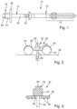
- Fig. 1 shows a fastening element 10 according to the invention with a dowel sleeve 12 made of plastic and an impact element 14.
- the impact element 14 expands the dowel sleeve 12 in sections in the radial direction when the impact element 14 is driven into the dowel sleeve 12.
- the expansion area 16 of the dowel sleeve 12 is expanded in the radial direction and thereby anchored in an object, in particular in a drilled hole of the object, when the impact element 14 is driven into the dowel sleeve 12, in Fig. 1 i.e. moved to the right into the dowel sleeve 12.
- the driving element 14 has a head 18 and a shaft 20.
- the shaft 20 is provided with a buttress thread 22 in sections.
- the buttress thread 22 is designed such that it can be driven into the dowel sleeve 12 to the right. However, the buttress thread 22 then offers greater resistance against the driving element 14 being pulled out of the dowel sleeve to the left.
- the driving element 14 can also be screwed into and out of the dowel sleeve 12 using the buttress thread 22.
- the driving element 14 can also be unscrewed from the dowel sleeve 12 again after driving in.
- the head 18 has an external drive formation 24 and an impact section 26.
- the external drive formation 24 is designed as an external hexagon.
- the impact section 26 has a cylindrical shape, in the illustrated embodiment a circular cylindrical shape.
- the impact section 26 adjoins the external drive formation 24 in the direction of the free end of the head 18, in Fig. 1 the impact section 26 is therefore arranged to the left of the external drive formation 24.
- a contact section 28 is arranged between the head 18 and the shaft 20 of the impact element 14.
- the contact section 28 is disc-shaped and formed integrally with the head 18 and the shaft 14.
- the contact section 28 has a significantly larger outer diameter than the shaft 20. Specifically, the outer diameter of the contact section 28 is at least three times as large as the outer diameter of the shaft 20. In the illustrated embodiment, the outer diameter of the contact section 28 is approximately five times as large as the outer diameter of the shaft 20.
- the contact section 28 exerts a preload force on a workpiece for pre-fixing.
- a through hole is first drilled in the workpiece and a drill hole in the object.
- the drill hole in the object for example in a concrete floor, is usually designed as a
- the fastening element 10 is then inserted through the through hole in the workpiece and sectionally into the borehole of the object. This can be done so far that the Fig. 1 left end of the dowel sleeve 12 rests against the top side of the workpiece and the expansion area 16 is completely arranged within the object.
- Pre-fixing of the workpiece to the object for example to a concrete floor, can then be carried out very easily by driving the impact element 14 into the dowel sleeve 12 with a hammer until the contact section 28 rests on the workpiece.
- the impact element 14 With the correct dimensioning of the length of the impact element 14, the thickness of the workpiece and the length of the dowel sleeve 12, the impact element 14 then spreads open the expansion area 16 of the dowel sleeve 12 so that the fastening element is anchored in the drilled hole in the object by frictional engagement. The workpiece is then also pre-fixed to the object.
- the holding force of the fastening element 10 according to the invention is significantly lower than the holding force required for final fastening of the workpiece to the object.
- the holding force that can be applied with the fastening element 10 according to the invention is a factor of 5, in particular a factor of 10, or a factor between 5 and 10 lower than the holding force of a second fastening element, with which final fixation is then carried out.
- the purpose of the fastening element according to the invention is the pre-fixation of the workpiece to the object in order to be able to easily place the second fastening elements in exactly the desired position or, for example, to be able to wait for an adhesive between the workpiece and the object to harden without the workpiece having to be held in place the entire time.
- the fastening element 10 according to the invention can also be intended to fix the workpiece to the object in order to then be able to solder or weld the workpiece to the object.
- the impact section 26 When driving the impact element 14 into the dowel sleeve 12, the impacts are applied to the impact section 26.
- the impact section 26 inevitably deforms and increases its outer diameter.
- the impact section 26 serves as a sacrificial section.
- the outer diameter of the impact section 26 is smaller than the outer diameter of the external drive formation 24. Even if the impact section 26 deforms so that its outer diameter becomes larger, this does not impair the ability to unscrew the impact element 14 via the external drive formation 24.
- a screw socket can be inserted over the external drive formation 24 so that the impact element 14 can be unscrewed very quickly, for example using a cordless screwdriver or the like.
- the outer diameter of the impact section is 10% to 25% smaller than a diameter cut into the outer contour of the
- the outer drive formation 24 is an inscribed circle. In such a case, there is no risk that the impact section 26 will increase its diameter so much when driving in the impact element 14 that it protrudes beyond the outer contour of the outer drive formation 24.
- the prestressing force with which the expansion section 16 is pressed radially outward against the inner wall of the drilled hole in the object is significantly reduced, and in particular reduced to a value close to zero.
- the dowel sleeve 12 can thus be very easily pulled out of the drilled hole and also pulled through the through hole in the workpiece. This can be done, for example, by applying a force to the contact section 28 in Fig. 1 is pulled to the left.
- second fastening elements are inserted to finally fasten the workpiece to the object with the prescribed holding force.
- a second fastening element can then be inserted and secured, for example, into the existing through-hole and into the existing drilled hole.
- the advantage of the fastening element 10 according to the invention lies in the fact that pre-fixing can be achieved very quickly by simply inserting and hammering in.
- the holding force of the pre-fixing only needs to be large enough to allow the final fixation of the workpiece to the object, for example, by drilling holes and using second fastening elements or by firmly bonding the workpiece to the object.
- Fig. 2 shows a partial sectional view of a fastening element 30 according to a further embodiment of the invention.
- the dowel sleeve 12 is in Fig. 2 Not shown for the sake of simplicity.
- the fastening element 30 is intended to pre-fix a structural steel structure 32 to a concrete floor 36.
- the impact element 34 of the fastening element 30 differs from the impact element 14 of the embodiment of the Fig. 1 only by having a different formed contact section 38 is provided.
- the impact section 26, the external drive formation 24 and the shaft 20 of the impact element 34 are designed exactly the same as the impact element 14 of the Fig. 1 and are therefore not explained again.
- Annex section 38 is in Fig. 2 shown only schematically and has two groove-shaped recesses 40.
- the groove-shaped recesses 40 are each intended to receive and fix a section of the structural steel structure 32.
- the representation of the Fig. 3 shows a fastening element 50 according to the invention according to a further embodiment in a sectional view.
- the dowel sleeve 12 is not shown for the sake of simplicity.
- An impact element 54 has a head with an impact section 26 and an external drive section 24, which are of the same design as the impact element 14 of Fig. 1 and therefore need not be explained again.
- the shaft 20 of the impact element 54 is also designed in the same way as the impact element 14 of the Fig. 1
- the dowel sleeve not shown also corresponds to the dowel sleeve 12 of the Fig. 1 .
- a contact section 58 is designed as a washer that is threaded onto the shaft 20.
- An outer diameter of the head on the underside of the external drive formation 24 is larger than a through-hole 60 of the washer that forms the contact section 58.
- An inner diameter of the through-hole 60 is significantly larger, in particular 1.5 times to 3 times, especially 2 times, as large as the outer diameter of the shaft 20.
- the contact section 58 can thus be moved relative to the shaft. Even when the impact element 54 has already been driven into the dowel sleeve 12 and a preload force is thereby exerted on the workpiece by the underside of the contact section 58, the workpiece can still be moved relative to the object, for example, by light hammer blows laterally against the workpiece. The contact section 58 can then be displaced together with the workpiece relative to the shaft 20.
- the underside of the contact section 58 facing the workpiece is provided with an anti-slip design.
- This anti-slip design is in the form of serrated projections 62.
- the serrated projections 62 dig into the upper side of the workpiece, which may be made of wood, for example.
- the contact section 58 is thereby fixed relative to the workpiece. When aligning the workpiece relative to the object, the contact section 58 can then be moved together with the workpiece relative to the shaft 20 of the impact element 54 and thus relative to the object without completely removing any pre-fixing, since a pre-tensioning force is still exerted on the workpiece by means of the fastening element 50 according to the invention.
- Fig. 4 shows several steps in fastening a workpiece 70 to an object 72 with a fastening element 80 according to another embodiment of the invention.
- the workpiece 70 is designed, for example, as a railing or handrail section.
- the object 72 is a section of masonry, for example, a building wall.
- step a a through hole is made in the workpiece 70 and after penetrating the workpiece 70, a blind hole is made in the object 72.
- step b after cleaning the drilled hole and the through-hole, the fastening element 80 according to the invention is inserted into the through-hole in the workpiece 70 and the drilled hole in the object 72. This is symbolized by two arrows above the dowel sleeve 82 and above the impact element 84.
- step c the dowel sleeve 82 has been inserted into the workpiece 70 and the object 72 to such an extent that a head of the dowel sleeve 82 rests on an upper side of the workpiece 70 facing away from the object 72.
- the expansion section of the dowel sleeve 82 lies completely within the object 72.
- the impact element 84 is now driven into the dowel sleeve 82 with a few hammer blows on the impact section 26.
- the impact or driving of the impact element 84 continues until the state in step d is reached.
- a contact section 88 of the fastening element 80 now rests on the upper side of the workpiece 70, which faces away from the object 72.
- the impact element 84 has completely penetrated the dowel sleeve 82 and thereby spread it radially outward in the area in which the dowel sleeve 82 is arranged in the drilled hole in the object 72.
- the contact section 88 pre-tensions the workpiece 70 against the object 72.
- the holding force exerted on the workpiece 70 by means of the fastening element 80 is substantially smaller than a holding force with which the workpiece 70 is finally fixed to the Object 72 must be fastened.
- the first holding force exerted by the fastening element 80 is smaller by a factor of 5 to a factor of 10 than the second holding force with which the workpiece 70 must be held to the object 72 in the finally assembled state.
- the second holding force is a holding force that is applied, for example, by a single second fastening element.
- the contact section 88 is designed as a sheet metal strip with a slight angle at its free ends.
- the contact section 88 can therefore be slightly resilient to reliably pre-fix the workpiece 70 to the object 72.
- the object 70 is finally fixed to the object 72.
- the fastening element 80 can be removed. This is done by unscrewing the impact element 84 from the dowel sleeve 82 using the external drive formation 24 at least until the impact element is completely or almost completely removed from the drilled hole in the object 72 and thus from the expansion area of the dowel sleeve 82.
- the expansion section of the dowel sleeve 82 is no longer pushed radially outwards and the impact element 84 can be easily pulled out together with the dowel sleeve 82 from the drilled hole in the object 72 and the through-opening in the workpiece 70, in the illustration of the Fig. 4 to the left.
- a second fastening element for example a plastic dowel with a screw, can then be inserted into the drilled hole in the object 72 and the through opening in the workpiece 70.
- the fastening element according to the invention and the method according to the invention enable a very simple and, above all, rapid pre-fixing of a workpiece to an object.
- the workpiece can thus be held in the intended final position on the object, allowing for the final fastening or fixing of the workpiece to the object.
- the final fixing can be achieved, for example, by second fastening elements, but also by means of a material bond, for example, by gluing, soldering, or welding.
Landscapes
- Engineering & Computer Science (AREA)
- General Engineering & Computer Science (AREA)
- Mechanical Engineering (AREA)
- Dowels (AREA)
- Insertion Pins And Rivets (AREA)
Applications Claiming Priority (1)
| Application Number | Priority Date | Filing Date | Title |
|---|---|---|---|
| DE102022208997.9A DE102022208997A1 (de) | 2022-08-30 | 2022-08-30 | Befestigungselement und Verfahren zum Befestigen |
Publications (2)
| Publication Number | Publication Date |
|---|---|
| EP4332391A1 EP4332391A1 (de) | 2024-03-06 |
| EP4332391B1 true EP4332391B1 (de) | 2025-06-18 |
Family
ID=87845942
Family Applications (1)
| Application Number | Title | Priority Date | Filing Date |
|---|---|---|---|
| EP23193557.8A Active EP4332391B1 (de) | 2022-08-30 | 2023-08-25 | Befestigungselement und verfahren zum befestigen |
Country Status (5)
| Country | Link |
|---|---|
| EP (1) | EP4332391B1 (pl) |
| DE (1) | DE102022208997A1 (pl) |
| DK (1) | DK4332391T3 (pl) |
| ES (1) | ES3039111T3 (pl) |
| PL (1) | PL4332391T3 (pl) |
Family Cites Families (6)
| Publication number | Priority date | Publication date | Assignee | Title |
|---|---|---|---|---|
| DE3018975A1 (de) | 1980-05-17 | 1981-11-26 | Groh, Karl-Friedrich, 7118 Künzelsau | Befestigungssatz |
| DE4123754C2 (de) | 1991-07-18 | 1993-11-04 | Bettermann Obo Ohg | Kabelschelle |
| DE20200292U1 (de) | 2002-01-10 | 2002-03-28 | Friedhelm Nolte GmbH, 33739 Bielefeld | Befestigungselement für ein an einer Wand befestigbares Bauteil |
| DE10229577A1 (de) * | 2002-07-02 | 2004-01-15 | Fischerwerke Artur Fischer Gmbh & Co. Kg | Spreizdübel aus Kunststoff |
| DE102004052184A1 (de) | 2004-10-27 | 2006-05-04 | Fischerwerke Artur Fischer Gmbh & Co. Kg | Nageldübel |
| JP6919406B2 (ja) | 2017-08-10 | 2021-08-18 | トヨタ自動車株式会社 | 車両側部構造 |
-
2022
- 2022-08-30 DE DE102022208997.9A patent/DE102022208997A1/de active Pending
-
2023
- 2023-08-25 PL PL23193557.8T patent/PL4332391T3/pl unknown
- 2023-08-25 ES ES23193557T patent/ES3039111T3/es active Active
- 2023-08-25 DK DK23193557.8T patent/DK4332391T3/da active
- 2023-08-25 EP EP23193557.8A patent/EP4332391B1/de active Active
Also Published As
| Publication number | Publication date |
|---|---|
| EP4332391A1 (de) | 2024-03-06 |
| DK4332391T3 (da) | 2025-08-25 |
| ES3039111T3 (en) | 2025-10-17 |
| PL4332391T3 (pl) | 2025-10-20 |
| DE102022208997A1 (de) | 2024-02-29 |
Similar Documents
| Publication | Publication Date | Title |
|---|---|---|
| EP1857607B1 (de) | Befestigungelement und Verfahren zur Befestigung von Dämmstoffplatten | |
| EP2666919B1 (de) | Verfahren und Befestigungssystem zum Anbringen von Dämmstoffplatten an einem Untergrund | |
| DE3607607A1 (de) | Befestigung von dichtungsbahnen und/oder daemmplatten am flachdach und dafuer bestimmte befestigungseinrichtung | |
| EP2397705B1 (de) | Verankerungssystem zum beabstandeten spannungsfreien Montieren eines Anbauteils an einen Verankerungsgrund | |
| DE10341401A1 (de) | Verbundeinrichtung für eine Holz-Beton-Verbindung | |
| EP0564889A1 (de) | Verbindungseinrichtung für ein insbesondere rohrförmiges Bauteil | |
| EP2977528B1 (de) | Verstärkungsanordnung für ein bauwerk und verfahren zum verstärken eines bauwerks mit einer derartigen verstärkungsanordnung | |
| EP4332391B1 (de) | Befestigungselement und verfahren zum befestigen | |
| EP0728882B1 (de) | Befestigungselement zum Befestigen von Platten grosser Dicke an Bauteilen | |
| DE3333055C2 (de) | Vorrichtung zum Befestigen von Latten | |
| EP1591602B1 (de) | Befestigungssystem für Bauteile an einer Wand | |
| EP3173632B1 (de) | Betonanker, betonankersystem, befestigungsanordnung und verfahren zum herstellen einer befestigungsanordnung | |
| DE29504559U1 (de) | Selbstbohrende Schraube | |
| EP0995914B1 (de) | Befestigungselement aus Metall mit Innengewinde für die Durchsteckmontage | |
| EP3702629B1 (de) | Universelles montageset zum montieren eines rahmens an einem untergrund | |
| EP0286706A1 (de) | Dübelelement | |
| EP0823562B1 (de) | Schlaganker zur Befestigung an dünnwandigen Betonteilen | |
| EP3322904B1 (de) | Verfahren zur herstellung einer verbindung | |
| EP4301991B1 (de) | Verfahren und system zum nivellieren eines in einem untergrund zu verankernden befestigungselements | |
| WO2014078969A1 (de) | Anschlaghalter für schalungen | |
| DE4408159C2 (de) | Verfahren zum Einbringen eines Dübels in Porenbeton | |
| DE4435537C2 (de) | Verankerung für Fertigteile | |
| WO1994012742A1 (de) | Verfahren und anordnung zur befestigung von fassadenplatten | |
| CH433671A (de) | Vorrichtung zum Verbinden von Fenster- oder Türrahmen oder dergleichen mit dem Mauerwerk | |
| WO2026021649A1 (de) | Befestiger |
Legal Events
| Date | Code | Title | Description |
|---|---|---|---|
| PUAI | Public reference made under article 153(3) epc to a published international application that has entered the european phase |
Free format text: ORIGINAL CODE: 0009012 |
|
| STAA | Information on the status of an ep patent application or granted ep patent |
Free format text: STATUS: THE APPLICATION HAS BEEN PUBLISHED |
|
| AK | Designated contracting states |
Kind code of ref document: A1 Designated state(s): AL AT BE BG CH CY CZ DE DK EE ES FI FR GB GR HR HU IE IS IT LI LT LU LV MC ME MK MT NL NO PL PT RO RS SE SI SK SM TR |
|
| STAA | Information on the status of an ep patent application or granted ep patent |
Free format text: STATUS: REQUEST FOR EXAMINATION WAS MADE |
|
| 17P | Request for examination filed |
Effective date: 20240729 |
|
| RBV | Designated contracting states (corrected) |
Designated state(s): AL AT BE BG CH CY CZ DE DK EE ES FI FR GB GR HR HU IE IS IT LI LT LU LV MC ME MK MT NL NO PL PT RO RS SE SI SK SM TR |
|
| GRAP | Despatch of communication of intention to grant a patent |
Free format text: ORIGINAL CODE: EPIDOSNIGR1 |
|
| STAA | Information on the status of an ep patent application or granted ep patent |
Free format text: STATUS: GRANT OF PATENT IS INTENDED |
|
| INTG | Intention to grant announced |
Effective date: 20250113 |
|
| GRAS | Grant fee paid |
Free format text: ORIGINAL CODE: EPIDOSNIGR3 |
|
| RAP1 | Party data changed (applicant data changed or rights of an application transferred) |
Owner name: WUERTH INTERNATIONAL AG Owner name: ADOLF WUERTH GMBH & CO. KG |
|
| GRAA | (expected) grant |
Free format text: ORIGINAL CODE: 0009210 |
|
| STAA | Information on the status of an ep patent application or granted ep patent |
Free format text: STATUS: THE PATENT HAS BEEN GRANTED |
|
| AK | Designated contracting states |
Kind code of ref document: B1 Designated state(s): AL AT BE BG CH CY CZ DE DK EE ES FI FR GB GR HR HU IE IS IT LI LT LU LV MC ME MK MT NL NO PL PT RO RS SE SI SK SM TR |
|
| REG | Reference to a national code |
Ref country code: GB Ref legal event code: FG4D Free format text: NOT ENGLISH |
|
| REG | Reference to a national code |
Ref country code: CH Ref legal event code: EP |
|
| REG | Reference to a national code |
Ref country code: DE Ref legal event code: R096 Ref document number: 502023001177 Country of ref document: DE |
|
| REG | Reference to a national code |
Ref country code: CH Ref legal event code: EP |
|
| REG | Reference to a national code |
Ref country code: IE Ref legal event code: FG4D Free format text: LANGUAGE OF EP DOCUMENT: GERMAN |
|
| REG | Reference to a national code |
Ref country code: DK Ref legal event code: T3 Effective date: 20250818 |
|
| P01 | Opt-out of the competence of the unified patent court (upc) registered |
Free format text: CASE NUMBER: UPC_APP_3804_4332391/2025 Effective date: 20250820 |
|
| PG25 | Lapsed in a contracting state [announced via postgrant information from national office to epo] |
Ref country code: FI Free format text: LAPSE BECAUSE OF FAILURE TO SUBMIT A TRANSLATION OF THE DESCRIPTION OR TO PAY THE FEE WITHIN THE PRESCRIBED TIME-LIMIT Effective date: 20250618 |
|
| PGFP | Annual fee paid to national office [announced via postgrant information from national office to epo] |
Ref country code: ES Payment date: 20250926 Year of fee payment: 3 |
|
| PGFP | Annual fee paid to national office [announced via postgrant information from national office to epo] |
Ref country code: DK Payment date: 20250825 Year of fee payment: 3 Ref country code: DE Payment date: 20250820 Year of fee payment: 3 |
|
| REG | Reference to a national code |
Ref country code: LT Ref legal event code: MG9D |
|
| PG25 | Lapsed in a contracting state [announced via postgrant information from national office to epo] |
Ref country code: NO Free format text: LAPSE BECAUSE OF FAILURE TO SUBMIT A TRANSLATION OF THE DESCRIPTION OR TO PAY THE FEE WITHIN THE PRESCRIBED TIME-LIMIT Effective date: 20250918 Ref country code: GR Free format text: LAPSE BECAUSE OF FAILURE TO SUBMIT A TRANSLATION OF THE DESCRIPTION OR TO PAY THE FEE WITHIN THE PRESCRIBED TIME-LIMIT Effective date: 20250919 |
|
| PGFP | Annual fee paid to national office [announced via postgrant information from national office to epo] |
Ref country code: IT Payment date: 20250901 Year of fee payment: 3 |
|
| PG25 | Lapsed in a contracting state [announced via postgrant information from national office to epo] |
Ref country code: BG Free format text: LAPSE BECAUSE OF FAILURE TO SUBMIT A TRANSLATION OF THE DESCRIPTION OR TO PAY THE FEE WITHIN THE PRESCRIBED TIME-LIMIT Effective date: 20250618 |
|
| PG25 | Lapsed in a contracting state [announced via postgrant information from national office to epo] |
Ref country code: HR Free format text: LAPSE BECAUSE OF FAILURE TO SUBMIT A TRANSLATION OF THE DESCRIPTION OR TO PAY THE FEE WITHIN THE PRESCRIBED TIME-LIMIT Effective date: 20250618 |
|
| REG | Reference to a national code |
Ref country code: ES Ref legal event code: FG2A Ref document number: 3039111 Country of ref document: ES Kind code of ref document: T3 Effective date: 20251017 |
|
| PGFP | Annual fee paid to national office [announced via postgrant information from national office to epo] |
Ref country code: FR Payment date: 20250828 Year of fee payment: 3 Ref country code: AT Payment date: 20251020 Year of fee payment: 3 |
|
| PG25 | Lapsed in a contracting state [announced via postgrant information from national office to epo] |
Ref country code: RS Free format text: LAPSE BECAUSE OF FAILURE TO SUBMIT A TRANSLATION OF THE DESCRIPTION OR TO PAY THE FEE WITHIN THE PRESCRIBED TIME-LIMIT Effective date: 20250918 |
|
| REG | Reference to a national code |
Ref country code: NL Ref legal event code: MP Effective date: 20250618 |
|
| PG25 | Lapsed in a contracting state [announced via postgrant information from national office to epo] |
Ref country code: LV Free format text: LAPSE BECAUSE OF FAILURE TO SUBMIT A TRANSLATION OF THE DESCRIPTION OR TO PAY THE FEE WITHIN THE PRESCRIBED TIME-LIMIT Effective date: 20250618 |
|
| PG25 | Lapsed in a contracting state [announced via postgrant information from national office to epo] |
Ref country code: NL Free format text: LAPSE BECAUSE OF FAILURE TO SUBMIT A TRANSLATION OF THE DESCRIPTION OR TO PAY THE FEE WITHIN THE PRESCRIBED TIME-LIMIT Effective date: 20250618 |
|
| PG25 | Lapsed in a contracting state [announced via postgrant information from national office to epo] |
Ref country code: PT Free format text: LAPSE BECAUSE OF FAILURE TO SUBMIT A TRANSLATION OF THE DESCRIPTION OR TO PAY THE FEE WITHIN THE PRESCRIBED TIME-LIMIT Effective date: 20251020 |
|
| PG25 | Lapsed in a contracting state [announced via postgrant information from national office to epo] |
Ref country code: IS Free format text: LAPSE BECAUSE OF FAILURE TO SUBMIT A TRANSLATION OF THE DESCRIPTION OR TO PAY THE FEE WITHIN THE PRESCRIBED TIME-LIMIT Effective date: 20251018 |
|
| PG25 | Lapsed in a contracting state [announced via postgrant information from national office to epo] |
Ref country code: SM Free format text: LAPSE BECAUSE OF FAILURE TO SUBMIT A TRANSLATION OF THE DESCRIPTION OR TO PAY THE FEE WITHIN THE PRESCRIBED TIME-LIMIT Effective date: 20250618 |
|
| PG25 | Lapsed in a contracting state [announced via postgrant information from national office to epo] |
Ref country code: CZ Free format text: LAPSE BECAUSE OF FAILURE TO SUBMIT A TRANSLATION OF THE DESCRIPTION OR TO PAY THE FEE WITHIN THE PRESCRIBED TIME-LIMIT Effective date: 20250618 |
|
| PGFP | Annual fee paid to national office [announced via postgrant information from national office to epo] |
Ref country code: PL Payment date: 20250816 Year of fee payment: 3 |
|
| PG25 | Lapsed in a contracting state [announced via postgrant information from national office to epo] |
Ref country code: EE Free format text: LAPSE BECAUSE OF FAILURE TO SUBMIT A TRANSLATION OF THE DESCRIPTION OR TO PAY THE FEE WITHIN THE PRESCRIBED TIME-LIMIT Effective date: 20250618 |
|
| PG25 | Lapsed in a contracting state [announced via postgrant information from national office to epo] |
Ref country code: SK Free format text: LAPSE BECAUSE OF FAILURE TO SUBMIT A TRANSLATION OF THE DESCRIPTION OR TO PAY THE FEE WITHIN THE PRESCRIBED TIME-LIMIT Effective date: 20250618 |