EP4331985A1 - Modular fluid storage and release system and aircraft provided with such a system - Google Patents
Modular fluid storage and release system and aircraft provided with such a system Download PDFInfo
- Publication number
- EP4331985A1 EP4331985A1 EP23192069.5A EP23192069A EP4331985A1 EP 4331985 A1 EP4331985 A1 EP 4331985A1 EP 23192069 A EP23192069 A EP 23192069A EP 4331985 A1 EP4331985 A1 EP 4331985A1
- Authority
- EP
- European Patent Office
- Prior art keywords
- tank
- aircraft
- tubes
- opening
- tube
- Prior art date
- Legal status (The legal status is an assumption and is not a legal conclusion. Google has not performed a legal analysis and makes no representation as to the accuracy of the status listed.)
- Pending
Links
- 239000012530 fluid Substances 0.000 title claims abstract description 27
- XLYOFNOQVPJJNP-UHFFFAOYSA-N water Substances O XLYOFNOQVPJJNP-UHFFFAOYSA-N 0.000 abstract description 51
- 230000005484 gravity Effects 0.000 description 7
- 239000002689 soil Substances 0.000 description 3
- 230000007246 mechanism Effects 0.000 description 2
- 230000002787 reinforcement Effects 0.000 description 2
- 239000010426 asphalt Substances 0.000 description 1
- 230000003247 decreasing effect Effects 0.000 description 1
- 230000003111 delayed effect Effects 0.000 description 1
- 238000010586 diagram Methods 0.000 description 1
- 239000006185 dispersion Substances 0.000 description 1
- 239000011121 hardwood Substances 0.000 description 1
- 238000007726 management method Methods 0.000 description 1
- 239000003415 peat Substances 0.000 description 1
- 230000002093 peripheral effect Effects 0.000 description 1
- 230000000717 retained effect Effects 0.000 description 1
- 238000007789 sealing Methods 0.000 description 1
- 239000011122 softwood Substances 0.000 description 1
Images


Classifications
-
- B—PERFORMING OPERATIONS; TRANSPORTING
- B64—AIRCRAFT; AVIATION; COSMONAUTICS
- B64D—EQUIPMENT FOR FITTING IN OR TO AIRCRAFT; FLIGHT SUITS; PARACHUTES; ARRANGEMENTS OR MOUNTING OF POWER PLANTS OR PROPULSION TRANSMISSIONS IN AIRCRAFT
- B64D1/00—Dropping, ejecting, releasing, or receiving articles, liquids, or the like, in flight
- B64D1/16—Dropping or releasing powdered, liquid, or gaseous matter, e.g. for fire-fighting
-
- A—HUMAN NECESSITIES
- A62—LIFE-SAVING; FIRE-FIGHTING
- A62C—FIRE-FIGHTING
- A62C3/00—Fire prevention, containment or extinguishing specially adapted for particular objects or places
- A62C3/02—Fire prevention, containment or extinguishing specially adapted for particular objects or places for area conflagrations, e.g. forest fires, subterranean fires
- A62C3/0228—Fire prevention, containment or extinguishing specially adapted for particular objects or places for area conflagrations, e.g. forest fires, subterranean fires with delivery of fire extinguishing material by air or aircraft
- A62C3/0235—Fire prevention, containment or extinguishing specially adapted for particular objects or places for area conflagrations, e.g. forest fires, subterranean fires with delivery of fire extinguishing material by air or aircraft by means of containers, e.g. buckets
Definitions
- the present invention relates to a system for storing and releasing fluid and more particularly water or products such as a retardant integrated into a host aircraft making it possible to convert it into a water bomber aircraft used for fighting fires in particular. of forests.
- the invention applies to all types of aircraft capable of receiving such a system and in particular to civil and military aircraft.
- the present invention aims to provide a modular water storage and release system capable of being easily introduced and removed from a host aircraft and capable of releasing water outside the aircraft at a sufficient rate.
- the present invention relates to a fluid storage and release system for a host aircraft comprising a fluid reservoir and at least one tube, characterized in that the reservoir is connected to said or all of said tubes which are extends longitudinally from the reservoir such that when installed in a host aircraft, the tube(s) conducts fluid to the longitudinal end of a rear door of the aircraft in the open position.
- the system is simple and easy to introduce and uninstall from a host aircraft.
- the invention provides at least one of the following optional characteristics, taken individually or in combination.
- the fluid storage and release system includes a transport and fixing support which with the reservoir and the tube(s) form a single piece.
- the transport and fixing support comprises a chassis comprising beams allowing the system to be transported and fixed in the aircraft.
- the chassis comprises lower longitudinal and/or transverse beams and the longitudinal and/or transverse beams comprise fixing means adapted for fixing to the aircraft.
- the transport and fixing support comprises a pallet on which is placed at least the tank allowing the system to be transported and fixed in the aircraft.
- the support has a determined length making it possible to distribute the load of the tank over said length.
- the system includes two tubes.
- the tubes are parallel to each other and the axes of the tubes are all included in the same plane.
- Pipes extend parallel to the tubes and one end of each pipe is connected to the tank and the other end extends in a direction different from the longitudinal direction of the tube(s).
- each pipe extends in a direction perpendicular to the longitudinal direction of the tube(s).
- the tank is provided with an opening at the top wall of the tank and a float in the tank for closing the opening when the tank is filled.
- the wall of the tank has a cavity towards the interior of the tank narrowing to the opening.
- the free end of the cavity is curved and is inserted into a narrowing of a float, the movement in a direction Z of the float then being blocked by a shoulder formed by an upper widening and a shoulder formed by a lower widening.
- the float is linked to a wall of the tank by an arm making it possible to guide the movement of the float and allow it to move away from and towards the opening and when applied against the opening to close it completely.
- a return spring connects the wall of the tank presenting the opening to the arm.
- the present invention also relates to the host aircraft comprising a rear door and an interior area into which is introduced a system having one or more of the aforementioned characteristics, the tubes of which extend to the longitudinal end of said rear door of the aircraft in the open position.
- the invention provides at least one of the following optional characteristics, taken individually or in combination.
- the tank is installed in an acceptable position relative to the center of gravity of the aircraft.
- the pipes extend over a distance allowing their end to come at a height laterally from the side edge of the rear door of the aircraft or set back towards the inside thereof.
- the following description refers to an orthonormal reference X, Y, Z (visible on the figures 1 and 2 ) in which the horizontal directions X,Y and vertical Z are defined with reference to an aircraft placed on horizontal ground.
- the three directions X, Y, Z are orthogonal to each other.
- the fuselage of the aircraft extends along a longitudinal direction X.
- the Y direction corresponds to the direction oriented transversely and horizontally with respect to the longitudinal direction
- Qualify as longitudinal respectively transverse, vertical means parallel to the longitudinal direction, respectively transverse, vertical.
- FIG 1 represents a military aircraft 2 type A400M (registered trademark) intended to be temporarily converted into a water bomber aircraft.
- the aircraft 2 includes a zone 4 offering useful interior free space. It also has a rear door 6 that can open in flight. There figure 1 represents door 6 in the closed position.
- the A400M is taken for illustrative purposes but other aircraft have similar characteristics, namely a zone 4 having a sufficient interior volume to accommodate a system 8 as described below and a rear door 6 allowing communication of zone 4 with the exterior of the aircraft could be suitable as a host aircraft 2.
- the fluid storage and release system 8 comprises a reservoir 10 of fluid arranged longitudinally and in the illustrated example of water, retardant or any other fluid used for fighting fire and at least one tube 12 extending longitudinally from the tank to which it is connected.
- Arrange or extend longitudinally means that the direction of the largest dimension is parallel to the longitudinal direction, namely the direction X.
- the fluid used is generally water but other types of fluid such as a retardant could be used depending on the fire to extinguish or even water combined with any type of product.
- the height Hr of the tank namely the largest dimension of the tank taken in the vertical Z direction, is greater than that Ht (largest dimension taken in the vertical Z direction) of the tube(s). 12.
- the height Ht corresponds to the diameter of cylindrical tubes of circular section like those shown in the figures.
- the height Hr is at least twice greater than the height Ht.
- the width Lr of the tank namely the largest dimension taken in the transverse direction Y, is greater than the largest width of the tube 12 or in the case of several tubes, the sum of the largest widths tubes 12: the width of a tube corresponds to its diameter for cylindrical tubes of circular section like those shown in the figures. Due to having a tube cross section of much smaller dimension than the cross section of the tank, the speed of the fluid flowing in the tube or tubes 12 from the tank is all the more important. These dimension ratios determine the flow velocity and are therefore chosen to have sufficient flow velocity for effective release of water from the aircraft.
- any other proportions in dimensions are possible.
- these can be arranged parallel to each other.
- all of the axes of the tubes are included in the same plane.
- two tubes 12 are provided but as seen previously any other number of tubes is possible.
- the two tubes 12 are cylindrical in shape with a circular section. They are parallel and their axes are included in the same plane parallel to the XY plane.
- the tubes extend in the longitudinal direction of the tank, namely in the direction of its length for a parallelepiped tank with a rectangular base and square section.
- the reservoir itself extending in a longitudinal direction. Any other embodiment is possible, namely tubes of different dimensions, positioned in different planes...
- the tube(s) extend so that once the system 8 is installed in the aircraft, the tube(s) 12 conduct the fluid to the end 20 longitudinally of the rear door 6 of the aircraft in the open position.
- the tubes 12 extend from the tank 10 to a water release device 14: their length is chosen so that one of the ends 16 of the tubes is connected with the tank 10 and the other end 18 with the device 14.
- the end 18 of the tubes once the system 8 in the release position, is located to the right of the end 20 (shown on the figure 4 ) free from the rear door 6.
- the release device 14 is entirely outside the cantilevered aircraft.
- the length of the tubes 12 also makes it possible to position the tank 10 at an acceptable distance from the center of gravity of the aircraft so as not to disturb its balance when it is filled and during release. The acceptable distance is in a known manner determined by a weight and balance diagram specific to each aircraft.
- the center of gravity of the tank alone filled with water is at an acceptable distance from the center of gravity of the aircraft.
- Each tube 12 is provided with a valve 13 at its connection with the tank.
- Each valve 13 is of known type, for example of type butterfly or conical shutter and will not be described further: it allows the communication between the tank and each tube to be opened and closed.
- one or more valves can also be positioned at the level of the release device 14 to adapt the water flow.
- the system 8 comprises valves 13 at the tank-tube connection and/or device 14-air connection external to the aircraft. Providing the tubes with valves 13 at their connection with the tank allows the aircraft to fly with the tank 10 filled with fluid and the tubes 12 empty.
- the tank By positioning the tank at an acceptable distance from the center of gravity of the aircraft, the balance of the aircraft is maintained. However, it is possible to move the tank to a position further from the center of gravity, for example to avoid the projection zone of the engine blades. In this case, providing the release device with valves makes it possible to fill the tubes (filled in flight) and to move the center of gravity of the complete system (compared to that of a system with empty tubes) so that it is at an acceptable distance from that of the aircraft.
- At least two pipes 22 extend in the longitudinal direction lower than that of the tubes 12.
- One of the ends 24 of the pipes is connected to the tank 10 and the other end 26 is located at the level of the rear door 6.
- the pipes 22 at the end 26 follow a direction different from the longitudinal direction and in the form illustrated a transverse direction. Indeed, the pipes 22 have a shape allowing their end 26 to come at the height transversely of the side edge of the rear door or set back relative to it towards the inside of the door so as to be able to close the door 6 during takeoff, landing and in certain phases of flight.
- the pipes 22 make it possible to supply the tank 10 from the ground.
- Each end 26 is connected to one or more vehicles on the ground, for example fire trucks, which allows the tank to be filled with water from the ground.
- the end 26 is designed to receive the typical flexible hose connectors of fire trucks.
- the plurality of pipes makes it possible to adapt the filling time. Being accessible from both sides of the aircraft allows a ground machine to park on either side of the aircraft knowing that it is also possible to have a machine on each side to speed up filling.
- three pipes 22 are provided along each of the two tubes 12, namely six pipes in all.
- the two so-called extremal tubes 12 in the case of more than two tubes correspond to the tubes located closest transversely to the walls of the aircraft.
- the pipes 22 are arranged at the lateral level of each of the extremal tubes 12 on the side opposite the adjacent tube.
- the pipes 22 are arranged one above the other along the vertical axis Z.
- the pipes 22 gradually move away transversely from the tubes 12. In the illustrated embodiment, the pipes move away until to be in a transverse direction Y at the edge of the rear door transversely. In the embodiment illustrated on the figure 4 , the end of the pipes 22 is located in the second half longitudinally of the rear door 6 closest to the end 20.
- the system 8 is provided with a means for warning people filling the tank that it is full. Several embodiments are possible.
- the tank 10 includes an opening 21 and a float 78 in the tank.
- the float 78 rises until it closes the opening 21.
- a conduit 80 connects the top of the tank to one of the tubes 12.
- a conduit connects the tank via a side face thereof, preferably that at which the tubes are connected and one of the tubes 12.
- a valve closing the opening and supported by a valve spring whose force is greater than that exerted by the water.
- the float closes the tank in the same way as before.
- the pressure rises and exceeds the maximum threshold set by the valve: the valve can no longer be kept closed.
- the valve opens and discharges the water into tube 12. The person in charge of filling the tank, seeing the water flowing through tube 12, knows that the tank is filled.
- the float 78 is connected to an internal wall 82 of the tank.
- the wall 82 is the wall of the tank located in a plane YZ closest to the opening 21.
- the float 78 is connected to the wall 82 by an arm 84 making it possible to guide the movement of the float.
- the connection between the arm 84 and the wall 82 allows rotation in a plane XZ authorizing the float 78 to move away and approach the opening 21 and when in contact with the tank to close said opening 21.
- the arm 84 thus allows the float 78 when pushed in the direction Z by the water towards the opening 21 to automatically close the opening 21. Any other means allowing the float to come to bear against the opening when pushed back by the water is possible.
- a return spring 86 connects the internal wall 88 of the tank provided with the opening 21 to the arm 84.
- the function of the return spring 86 once the desired quantity of water has been expelled from the aircraft, is to return the arm 84 in its primary position, namely against the opening 21.
- the opening 21 being closed, if the tank has only been partially emptied and the plane finds itself in turbulence, the water cannot be projected outside the tank by the opening 21 which is closed using the float 78 held against the opening by the return spring 86.
- the wall 88 can have a particular shape at the level of the opening 21.
- the float 78 can also have any type of shape. According to the embodiments illustrated on the figures 10 and 11 , the wall 88 at the level of the opening 21 extends towards the interior of the tank so as to form a cavity 90 narrowing until it forms the opening 21 at its lowest in the direction Z (when the aircraft is on the ground and the wall 82 is parallel to the Z axis).
- overflow management is carried out differently and not shown. It is possible to provide a valve which opens from a certain pressure for example.
- the float 78 has a shape having a narrowing 92 at the central level in the Z direction (when the aircraft is on the ground and the wall 82 is parallel to the Z axis).
- the edge 94 of the cavity at the level of the opening 21 is curved and oriented inwards to be inserted at the level of the constriction 92 of the float 78. In this case, no return spring is necessary since the float is retained by the extremal edge 94 of the cavity 90, blocked by the shoulder 96 formed by the upper widening 98 of the float or by the shoulder 100 formed by the lower widening 102 thereof.
- the narrowing 92 has a certain length in the Z direction to allow the float 78 to move in the Z direction.
- the wall of the cavity 90 as well as the particular shape of the float shield any projection of water which could be made towards outside the tank through opening 21.
- the system 8 includes a transport and fixing support 15 which with the tank 10 and the tube(s) 12 form a single unit.
- the following description presents two embodiments of the support 15.
- the support 15 comprises a chassis 28 comprising beams making it possible to transport the tank and the tube(s) and to fix them in the aircraft and for example to the floor 9 thereof.
- the chassis 28, the tank 10 and the tube(s) 12 form a single unit capable of being loaded and unloaded from the aircraft.
- the beams include fixing means of known type to the aircraft and for example to the floor 9 of the aircraft.
- the figures illustrate a possible form of chassis but any other form making it possible to form a single piece with the tank and the tube(s) 12 to transport the system 8 in one piece in the aircraft or to unload from it. This as well as for fixing in the aircraft is possible.
- the chassis 28 comprises four longitudinal beams 30, four transverse beams 32 and four vertical beams 34 forming a parallelepiped frame 36 of rectangular section.
- the reservoir 10 is in contact with all of the beams but does not extend beyond the reinforcement 36 formed.
- the two lower longitudinal beams 30 are extended longitudinally on either side of the frame 36 by four lower longitudinal extension beams 38.
- the upper ends 40 of each vertical beam 34 are linked by another beam 42 inclined to the ends 44 of the lower longitudinal extension beams 38.
- THE inclined beams 42 form supports for the frame 36 to reinforce its solidity.
- the mass of the chassis is distributed over a certain length of floor 9 in order to avoid overloading it locally and damaging it.
- the chassis also allows the tank to be maintained in position on the floor 9 of the aircraft.
- the beams 42 located on the side of the tubes 12 frame them over part of their length and in particular at the level of the connection zone of the tubes 12 with the tank.
- the beams also make it possible to be adapted to receive means of fixing the system 8 to the floor 9 of the aircraft.
- the support 15 comprises a pallet on which is arranged at least the tank making it possible to transport the tank and the tube(s) and to fix them in the aircraft and for example to the floor 9 of it.
- the pallet, the tank 10 and the tube(s) 12 form a single unit capable of being loaded and unloaded from the aircraft.
- the pallet comprises fixing means of known type to the aircraft and for example to the floor of the aircraft. It is then sufficient to carry the pallet inside the aircraft and slide it on the floor 9 to position the system in the desired location, some floors being equipped with casters.
- the system 8 is in one piece forming a modular assembly capable of being integrated into a host aircraft.
- the modular system 8 presented thus makes it possible to be installed temporarily in a host aircraft and to avoid having to modify it to accommodate this system 8.
- the system 8 can be installed and uninstalled at will depending on the program of the host aircraft concerned.
- the support has a determined length making it possible to distribute the load of the tank over said length as seen above for the illustrated example of the chassis. According to a possible embodiment, the length of the support (chassis or pallet) is at least equal to the length of the tank 10.
- the water release device 14 can have any type of shape.
- the water release device can be summed up in its simplest form as an extension of the tubes 12 and be integrated into the system 8. Indeed it could be envisaged to allow the ends 18 of the tubes 12 of the rear door 6 to protrude beyond the end 20 thereof.
- the modular system 8 is equipped with a device 14 for releasing fluid and in the example described for releasing water.
- the purpose of the water release device 14 is to modify the direction of the flow. From a longitudinal direction, the device 14 allows the water flow to flow in a different direction.
- the device 14 makes it possible to release the water in an appropriate direction and for example perpendicular to the longitudinal direction, namely a vertical direction Z or close to a vertical direction if the aircraft in flight is not located not in a horizontal position.
- the device 14 also has another advantage which is to distribute the release into several flows whose use can be independently controlled for each of the flows, namely authorized or not. Thus, depending on the intensity of the fire, only part of the flow could be used, which makes it possible to save a quantity of water for another fire, another location of the fire or for other purposes.
- the water release device comprises a closed tank 46 having at least one opening 48 for the entry of water and at least one opening 50 for the release of water towards the outside of the aircraft.
- the opening 48 has a shape allowing the tank to fit onto the tube(s) 12 so as to form a tight connection in a known manner.
- the tank has two openings 48A, 48B extending in the form of sleeves 52, 54 allowing connection with the tubes 12.
- the sleeves 52 , 54 have a cylindrical shape of circular section.
- the tank 46 comprises several independent openings 50A, 50B ... 50n.
- the openings 50A, 50B ... 50n abut each other.
- the openings 50A, 50B ... 50n are contiguous so as to circumscribe the whole in the same larger opening 51 of geometric shape determined by the shape of the openings 50A, 50B, ... 50n.
- each opening 50A, 50B ... 50n is rectangular in shape.
- the contiguous openings 50A, 50B ... 50n are circumscribed in the same large rectangular opening 51 split into several openings 50A, 50B, ... 50n.
- the openings 50A, 50B, ... 50n are included in a plan parallel to the XY, namely a plane perpendicular to a transverse plane YZ to the tubes.
- the openings 50A, 50B, ... 50n are oriented so as to guide the flows flowing through them towards the ground, namely in a vertical direction Z.
- the aircraft In flight, the aircraft can fly in a nose-up position.
- the rear door 6 in the open position can be located in the extension of the floor 9 of the aircraft.
- the release device 14 arranged beyond the door 6 but in its longitudinal extension is not in a horizontal position in flight.
- the plane in which the openings 50A, 50B...50n are arranged is chosen according to the desired water release direction.
- the tank has a shape making it possible to form water flow conduits 53A, 53B, ...
- each conduit 53n whose outlet orifice corresponds to each opening 50A, 50B ... 50n.
- the conduits are here of parallelepiped shape of rectangular section forming together a parallelepiped block of rectangular section whose outlet orifice corresponds to the rectangular opening 51.
- the external contours of the ducts could be rounded for aerodynamic purposes.
- the axis of each conduit 53A, 53B, ... 53n corresponds to the axis of the corresponding opening 50A, 50B ... 50n.
- the openings 50A, 50B ... 50n are each capable of being closed by a valve 55 taking, in the illustrated embodiment, the shape of a flap respectively 56A, 56B, ... 56n.
- each conduit 53A, 53B, ... 53n is provided with a flap 56A, 56B, ... 56n.
- the opening and closing of each shutter 56A, 56B,... 56n can be controlled independently for each shutter by a control device 58 described later.
- the flaps 56 make it possible to adjust the flow rate of released fluid.
- the tank 46 has the shape of a funnel, namely whose dimensions in a plane parallel to the XY plane decrease going vertically downwards, the largest dimension being at the height of the tubes so as to guide the water towards the opening(s) 50.
- the lowest part of the tank in the shape illustrated is the dimensions of the opening 51.
- the flaps 56 are each in the form of an articulated flat panel 60 around an axis parallel to the Y direction; the hinge pin is for each central panel longitudinally. In position open, the panels 60 are each in a plane parallel to the plane YZ and all parallel to each other.
- the panels 60 are in a plane parallel to the plane XY, contiguous, abutting each other without superposing each other, each closing the corresponding opening 50A, 50B, ... 50n and closing the aforementioned rectangular opening 51. Any other form of realization is possible.
- the tank 46 has a dimension in a plane parallel to the plane YZ decreasing longitudinally away from the openings 48. Any other shape of tank is possible as long as it has inlet openings 48 and openings 50 outlet allowing the change of direction of the flow to release the water in the direction of the fire and thus reduce its dispersion.
- the release device 14 is retractable. Indeed, to allow the rear door 6 to close, it is necessary that the device 14 does not protrude from the end 20 of the rear door.
- the release device is linked to the tube or said tubes 12 via a hinge arranged at the top of each of the tubes 12 and sleeves 52, 54 allowing the device to pivot around an axis transverse parallel to the direction Y.
- a peripheral seal is provided between the tube(s) 12 and the sleeve(s) 52, 54 to ensure sealing when the sleeve(s) are in the release position in the extension of the tube(s) 12.
- at least part of the tube(s) are made telescopically to be able to reduce in length and allow the release device 14 to no longer protrude from the end 20.
- the release device 14 is not retractable. Indeed, it is possible for certain host aircraft to fly with the rear door 6 open.
- the system 8 is controlled using a control device 58 capable of being manipulated directly by a pilot and/or a co-pilot and/or a third man in the cockpit and/or any other operator whose function is to trigger the release of water and/or prepare the appropriate quantity. Control could also be considered from the ground, the control device then being connected to the aircraft by any type of known wireless communication means.
- the device 58 represented by a rectangle in the aircraft in the example illustrated on the Figure 7 , is connected to system 8 to ensure control. According to the embodiment described above, the device 58 is connected to the valves 13 for closing the tubes 12 on the side of the tank and/or to the valves 55 (closing flaps 56).
- the device can be used by a third man 62 (only the seat on which he is intended to sit is shown) or from the cockpit 64 depending on the choice made by the pilot and/or the third man.
- a third man 62 only the seat on which he is intended to sit is shown
- the cockpit 64 depending on the choice made by the pilot and/or the third man.
- the following description presents a possible embodiment of the control device but any other form is possible.
- the control device 58 is in the form of a gun 66 having a trigger 68, a control panel 70 and a handle 72 for gripping.
- the control panel 70 presents means of configuring several criteria having an influence on the necessary quantity of water to be released. Thus it is possible to control the quantity of water using the valves 13 and/or 55 presented previously and this according to different criteria.
- the gun 66 includes an internal processor in which an algorithm is programmed to determine the quantity of water and more precisely the necessary flow and the duration according to the criteria entered.
- the control panel 70 includes thumbwheel buttons 74 to incrementally adjust each criterion. Each button 74 allows you to adjust a criterion.
- the altitude (A) of release of the aircraft - the speed (PS) of the aircraft; - wind speed (WS); - the soil concerned (VH) and for example the height and/or type of vegetation and/or the type of soil.
- A the altitude
- PS speed
- WS wind speed
- VH soil concerned
- the quantity of water required is not necessarily the same.
- Peat or bitumen soils should not be considered in the same way.
- Other criteria may be added via such a control panel or in a different way.
- the release rate can vary depending on the ground over which the aircraft is flying. In this case, it is no longer with the help of a button that the ground concerned is entered but with a recorded map of the ground flown over.
- the control panel 70 has a display screen 76 for displaying information. So for example, when the altitude button is manipulated, the selected altitude is displayed on the screen 76.
- Other types of display can be used such as for example simple light emitting diodes (LEDs) or lines of diodes electroluminescent.
Abstract
L'invention vise à proposer un système de stockage et de largage d'eau modulaire susceptible d'être facilement introduit et retiré d'un aéronef hôte de lutte contre le feu. Pour ce faire le système de stockage et de largage d'eau pour aéronef hôte comprend un réservoir (10) de fluide et au moins un tube (12). Le réservoir (10) est connecté audit ou à l'ensemble desdits tubes (12) qui s'étend(ent) longitudinalement depuis le réservoir (10) de manière qu'une fois installé dans l'aéronef hôte, le ou les tubes (12) conduisent le fluide jusqu'à l'extrémité longitudinalement d'une porte arrière de l'aéronef en position ouverte. La présente invention concerne également l'aéronef hôte équipé d'un tel système.The invention aims to provide a modular water storage and release system capable of being easily introduced and removed from a host firefighting aircraft. To do this, the water storage and release system for a host aircraft comprises a fluid reservoir (10) and at least one tube (12). The tank (10) is connected to said tube(s) (12) which extend(s) longitudinally from the tank (10) such that once installed in the host aircraft, the tube(s) ( 12) conduct the fluid to the longitudinal end of a rear door of the aircraft in the open position. The present invention also relates to the host aircraft equipped with such a system.
Description
La présente invention concerne un système de stockage et de largage de fluide et plus particulièrement d'eau ou de produits tels qu'un retardant intégré à un aéronef hôte permettant de le convertir en aéronef bombardier d'eau utilisé pour la lutte contre les incendies notamment de forêts. L'invention s'applique à tous les types d'aéronefs susceptibles de recevoir un tel système et notamment aux aéronefs civils et militaires.The present invention relates to a system for storing and releasing fluid and more particularly water or products such as a retardant integrated into a host aircraft making it possible to convert it into a water bomber aircraft used for fighting fires in particular. of forests. The invention applies to all types of aircraft capable of receiving such a system and in particular to civil and military aircraft.
Pour permettre de lutter plus efficacement contre les incendies de forêt, un renfort en aéronef bombardier d'eau serait utile. Il est donc envisagé de convertir temporairement des aéronefs non utilisés au moment de l'incendie ou dont l'utilisation peut être temporisée ou annulée, en aéronef bombardier d'eau. De tels aéronefs sont appelés aéronefs hôtes. Dès la fin de l'incendie, l'aéronef peut à nouveau remplir sa mission première. Ainsi, par exemple, des avions militaires comme l'A400M (marque déposée) sont particulièrement appropriés en temps de paix. Ce type d'avion de type cargo présente un volume intérieur susceptible d'embarquer un chargement comprenant un réservoir d'eau et un dispositif permettant de larguer l'eau à l'extérieur de l'avion. Lorsque le feu est éteint, il suffit de décharger l'aéronef pour l'utiliser comme avion militaire.To help fight forest fires more effectively, reinforcement by water bomber aircraft would be useful. It is therefore envisaged to temporarily convert aircraft not in use at the time of the fire or whose use can be delayed or cancelled, into water bomber aircraft. Such aircraft are called host aircraft. As soon as the fire is over, the aircraft can once again fulfill its primary mission. So, for example, military aircraft like the A400M (registered trademark) are particularly suitable in peacetime. This type of cargo-type aircraft has an interior volume capable of carrying a load comprising a water tank and a device for releasing the water outside the aircraft. When the fire is out, simply unload the aircraft for use as a military aircraft.
La présente invention vise à proposer un système de stockage et de largage d'eau modulaire susceptible d'être facilement introduit et retiré d'un avion hôte et permettant de larguer l'eau à l'extérieur de l'aéronef à un débit suffisant.The present invention aims to provide a modular water storage and release system capable of being easily introduced and removed from a host aircraft and capable of releasing water outside the aircraft at a sufficient rate.
A cet effet, la présente invention concerne un système de stockage et de largage de fluide pour aéronef hôte comprenant un réservoir de fluide et au moins un tube, caractérisé en ce que le réservoir est connecté audit ou à l'ensemble desdits tubes qui s'étend(ent) longitudinalement depuis le réservoir de manière qu'une fois installé dans un aéronef hôte, le ou les tubes conduisent le fluide jusqu'à l'extrémité longitudinalement d'une porte arrière de l'aéronef en position ouverte.To this end, the present invention relates to a fluid storage and release system for a host aircraft comprising a fluid reservoir and at least one tube, characterized in that the reservoir is connected to said or all of said tubes which are extends longitudinally from the reservoir such that when installed in a host aircraft, the tube(s) conducts fluid to the longitudinal end of a rear door of the aircraft in the open position.
De cette manière, le système est simple et facile à introduire et désinstaller d'un aéronef hôte.In this way, the system is simple and easy to introduce and uninstall from a host aircraft.
L'invention prévoit au moins l'une des caractéristiques optionnelles suivantes, prises isolément ou en combinaison.The invention provides at least one of the following optional characteristics, taken individually or in combination.
Le système de stockage et de largage de fluide comprend un support de transport et de fixation qui avec le réservoir et le ou les tubes forment un ensemble d'un seul tenant.The fluid storage and release system includes a transport and fixing support which with the reservoir and the tube(s) form a single piece.
Le support de transport et de fixation comporte un châssis comprenant des poutres permettant de transporter et fixer le système dans l'aéronef.The transport and fixing support comprises a chassis comprising beams allowing the system to be transported and fixed in the aircraft.
Le châssis comprend des poutres longitudinales et/ou transversales inférieures et les poutres longitudinales et/ou transversales comprennent des moyens de fixation adaptés pour la fixation à l'aéronef.The chassis comprises lower longitudinal and/or transverse beams and the longitudinal and/or transverse beams comprise fixing means adapted for fixing to the aircraft.
Le support de transport et de fixation comprend une palette sur laquelle est disposé au moins le réservoir permettant de transporter et fixer le système dans l'aéronef.The transport and fixing support comprises a pallet on which is placed at least the tank allowing the system to be transported and fixed in the aircraft.
Le support présente une longueur déterminée permettant de répartir la charge du réservoir sur ladite longueur.The support has a determined length making it possible to distribute the load of the tank over said length.
Le système comprend deux tubes.The system includes two tubes.
Les tubes sont parallèles les uns aux autres et les axes des tubes sont tous compris dans un même plan.The tubes are parallel to each other and the axes of the tubes are all included in the same plane.
Des tuyaux s'étendent parallèlement aux tubes et une des extrémités de chaque tuyau est connectée au réservoir et l'autre extrémité s'étend dans une direction différente de la direction longitudinale du ou des tubes.Pipes extend parallel to the tubes and one end of each pipe is connected to the tank and the other end extends in a direction different from the longitudinal direction of the tube(s).
L'autre extrémité de chaque tuyau s'étend dans une direction perpendiculaire à la direction longitudinale du ou des tubes.The other end of each pipe extends in a direction perpendicular to the longitudinal direction of the tube(s).
Le réservoir est muni d'une ouverture au niveau de la paroi supérieure du réservoir et d'un flotteur dans le réservoir destiné à fermer l'ouverture lorsque le réservoir est rempli.The tank is provided with an opening at the top wall of the tank and a float in the tank for closing the opening when the tank is filled.
La paroi du réservoir présente une cavité vers l'intérieur du réservoir allant en se rétrécissant jusqu'à l'ouverture.The wall of the tank has a cavity towards the interior of the tank narrowing to the opening.
L'extrémité libre de la cavité est courbée et vient s'insérer dans un rétrécissement d'un flotteur, le mouvement dans une direction Z du flotteur étant alors bloqué par un épaulement formé par un élargissement supérieur et un épaulement formé par un élargissement inférieur.The free end of the cavity is curved and is inserted into a narrowing of a float, the movement in a direction Z of the float then being blocked by a shoulder formed by an upper widening and a shoulder formed by a lower widening.
Le flotteur est lié à une paroi du réservoir par un bras permettant de guider le mouvement du flotteur et lui permettre de s'éloigner et de se rapprocher de l'ouverture et lorsqu'appliqué contre l'ouverture de la fermer complètement.The float is linked to a wall of the tank by an arm making it possible to guide the movement of the float and allow it to move away from and towards the opening and when applied against the opening to close it completely.
Un ressort de rappel lie la paroi du réservoir présentant l'ouverture au bras.A return spring connects the wall of the tank presenting the opening to the arm.
La présente invention concerne également l'aéronef hôte comprenant une porte arrière et une zone intérieure dans laquelle est introduit un système présentant une ou plusieurs des caractéristiques susmentionnées dont les tubes s'étendent jusqu'à l'extrémité longitudinalement de ladite porte arrière de l'aéronef en position ouverte.The present invention also relates to the host aircraft comprising a rear door and an interior area into which is introduced a system having one or more of the aforementioned characteristics, the tubes of which extend to the longitudinal end of said rear door of the aircraft in the open position.
L'invention prévoit au moins l'une des caractéristiques optionnelles suivantes, prises isolément ou en combinaison.The invention provides at least one of the following optional characteristics, taken individually or in combination.
Le réservoir est installé dans une position acceptable par rapport au centre de gravité de l'aéronef.The tank is installed in an acceptable position relative to the center of gravity of the aircraft.
Les tuyaux s'étendent sur une distance permettant à leur extrémité de venir à hauteur latéralement du bord latéral de la porte arrière de l'aéronef ou en retrait vers l'intérieur de celle-ci.The pipes extend over a distance allowing their end to come at a height laterally from the side edge of the rear door of the aircraft or set back towards the inside thereof.
D'autres buts, caractéristiques et avantages ressortiront de la description de l'invention qui va suivre, description donnée à titre d'exemple uniquement non limitatif, en référence aux dessins ci-annexés dans lesquels :
- [
Fig. 1 ] est une vue latérale d'un aéronef hôte selon la présente invention ; - [
Fig. 2 ] est une vue en perspective d'un système de stockage et de largage de fluide selon la présente invention ; - [
Fig. 3 ] est une vue latérale d'un aéronef hôte équipé d'un système de stockage et de largage de fluide selon la présente invention dans lequel l'intérieur de l'aéronef est découvert de manière schématisée en plan ; - [
Fig. 4 ] est une vue en perspective de la zone arrière d'un aéronef hôte en opération équipé d'un système de stockage et de largage de fluide selon la présente invention ; - [
Fig. 5 ] est une vue en perspective d'un certain angle de vue de dessous d'un dispositif de largage de fluide selon la présente invention ; - [
Fig. 6 ] est une vue en perspective d'un certain angle de vue de dessus d'un dispositif de largage de fluide selon la présente invention ; - [
Fig. 7 ] une vue en perspective d'un certain angle de vue latéral de la zone avant d'un aéronef équipé d'un système de stockage et de largage de fluide selon la présente invention dont l'intérieur est découvert pour mettre en évidence de manière schématisée un dispositif de contrôle dudit système ; - [
Fig. 8 ] est une vue en perspective du dispositif de contrôle proprement dit selon la présente invention ; - [
Fig. 9 ] une vue en en plan du panneau de contrôle du dispositif de contrôle selon la présente invention ; - [
Fig. 10 ] une vue partielle schématique de côté en coupe du réservoir, l'avion étant en vol dans une position inclinée ; - [
Fig. 11 ] une vue partielle schématique de côté en coupe du réservoir selon une autre forme de réalisation que celle de lafigure 10 , l'avion étant en vol dans une position inclinée.
- [
Fig. 1 ] is a side view of a host aircraft according to the present invention; - [
Fig. 2 ] is a perspective view of a fluid storage and release system according to the present invention; - [
Fig. 3 ] is a side view of a host aircraft equipped with a fluid storage and release system according to the present invention in which the interior of the aircraft is discovered schematically in plan; - [
Fig. 4 ] is a perspective view of the rear area of a host aircraft in operation equipped with a fluid storage and release system according to the present invention; - [
Fig. 5 ] is a perspective view of a certain bottom viewing angle of a fluid delivery device according to the present invention; - [
Fig. 6 ] is a perspective view of a certain top view angle of a fluid delivery device according to the present invention; - [
Fig. 7 ] a perspective view from a certain lateral angle of view of the front area of an aircraft equipped with a fluid storage and release system according to the present invention, the interior of which is uncovered to highlight in a schematic manner a device for controlling said system; - [
Fig. 8 ] is a perspective view of the control device itself according to the present invention; - [
Fig. 9 ] a plan view of the control panel of the control device according to the present invention; - [
Fig. 10 ] a partial schematic side sectional view of the tank, the aircraft being in flight in an inclined position; - [
Fig. 11 ] a partial schematic side sectional view of the tank according to another embodiment than that of theFigure 10 , the aircraft being in flight in an inclined position.
La description qui suit se réfère à un repère orthonormé X, Y, Z (visible sur les
La
Selon la présente invention, le système 8 de stockage et de largage de fluide comprend un réservoir 10 de fluide disposé longitudinalement et dans l'exemple illustré d'eau, de retardant ou tout autre fluide utilisé pour la lutte contre le feu et au moins un tube 12 s'étendant longitudinalement depuis le réservoir auquel il est connecté. Disposer ou s'étendre longitudinalement signifie que la direction de la plus grande dimension est parallèle à la direction longitudinale à savoir la direction X. Le fluide utilisé est en général de l'eau mais d'autres types de fluide tels qu'un retardant pourraient être utilisés suivant le feu à éteindre voire de l'eau combiné à tout type de produits. Dans la forme de réalisation illustrée, la hauteur Hr du réservoir, à savoir la dimension du réservoir la plus grande prise dans la direction Z verticale, est supérieure à celle Ht (dimension la plus grande prise dans la direction Z verticale) du ou des tubes 12. La hauteur Ht correspond au diamètre de tubes cylindriques de section circulaire comme ceux représentés sur les figures. Selon la forme de réalisation illustrée, la hauteur Hr est au moins deux fois supérieure à la hauteur Ht. Par ailleurs, la largeur Lr du réservoir, à savoir la dimension la plus grande prise dans la direction transversale Y, est supérieure à la largeur la plus grande du tube 12 ou dans le cas de plusieurs tubes, à la somme des largeurs les plus grandes des tubes 12 : la largeur d'un tube correspond à son diamètre pour des tubes cylindriques de section circulaire comme ceux représentés sur les figures. Du fait d'avoir une section transversale de tube de dimension bien plus faible que la section transversale du réservoir, la vitesse du fluide s'écoulant dans le ou les tubes 12 depuis le réservoir est d'autant plus importante. Ces rapports de dimension déterminent la vitesse d'écoulement et sont donc choisis pour avoir une vitesse d'écoulement suffisante pour un largage d'eau hors de l'aéronef efficace. Toutes autres proportions dans les dimensions est possible. Dans le cas de plusieurs tubes 12, ceux-ci peuvent être disposés parallèlement les uns aux autres. Dans le cas de tubes cylindriques de section circulaire, l'ensemble des axes des tubes sont compris dans un même plan. Dans la forme de réalisation illustrée, deux tubes 12 sont prévus mais comme vu précédemment tout autre nombre de tubes est envisageable. Les deux tubes 12 sont de forme cylindrique de section circulaire. Ils sont parallèles et leurs axes sont compris dans un même plan parallèle au plan XY. Les tubes s'étendent dans la direction longitudinale du réservoir à savoir dans la direction de sa longueur pour un réservoir parallélépipédique de base rectangulaire et section carré. Le réservoir s'étendant lui-même dans une direction longitudinale. Toute autre forme de réalisation est possible à savoir des tubes de dimensions différentes, positionnés dans des plans différents ... Le ou les tubes s'étendent de manière qu'une fois le système 8 installé dans l'aéronef, le ou les tubes 12 conduisent le fluide jusqu'à l'extrémité 20 longitudinalement de la porte arrière 6 de l'aéronef en position ouverte.According to the present invention, the fluid storage and release system 8 comprises a
Dans la forme illustrée, les tubes 12 s'étendent depuis le réservoir 10 jusqu'à un dispositif 14 de largage d'eau : leur longueur est choisie pour que l'une des extrémités 16 des tubes soit connectée avec le réservoir 10 et l'autre extrémité 18 avec le dispositif 14. Dans la forme de réalisation, l'extrémité 18 des tubes, une fois le système 8 en position de largage, se trouve au droit de l'extrémité 20 (représentée sur la
Au moins deux tuyaux 22 s'étendent dans la direction longitudinale X entre le réservoir 10 et la porte 6 arrière le long du ou desdits tubes 12. Dans le cas de tuyaux 22 et tubes 12 cylindriques de section circulaire, les tuyaux 22 sont de diamètre inférieur à celui des tubes 12. L'une des extrémités 24 des tuyaux est connectée au réservoir 10 et l'autre extrémité 26 se trouve au niveau de la porte 6 arrière. Les tuyaux 22 au niveau de l'extrémité 26 suivent une direction différente de la direction longitudinale et dans la forme illustrée une direction transversale. En effet, les tuyaux 22 présentent une forme permettant à leur extrémité 26 de venir à hauteur transversalement du bord latéral de la porte arrière ou en retrait par rapport à celui-ci vers l'intérieur de la porte de manière à pouvoir fermer la porte 6 au décollage, à l'atterrissage et dans certaines phases de vol. Les tuyaux 22 permettent d'alimenter le réservoir 10 depuis le sol. Chaque extrémité 26 est connectée à un ou plusieurs engins au sol par exemple des camions de pompier ce qui permet de remplir le réservoir en eau depuis le sol. Selon une forme de réalisation possible, l'extrémité 26 est conçue de manière à recevoir les raccords types de tuyaux souples des camions de pompier. La pluralité de tuyaux permet d'adapter le temps de remplissage. Le fait d'être accessible des deux côtés de l'aéronef permet à un engin au sol de stationner d'un côté ou de l'autre de l'aéronef sachant qu'il est aussi possible d'avoir un engin de chaque côté pour accélérer le remplissage. Dans la forme de réalisation illustrée, trois tuyaux 22 sont prévus le long de chacun des deux tubes 12, à savoir en tout six tuyaux. Les deux tubes 12 dits extrémaux dans le cas de plus de deux tubes correspondent aux tubes se trouvant au plus près transversalement des parois de l'aéronef. Les tuyaux 22 sont disposés au niveau latéral de chacun des tubes 12 extrémaux du côté opposé au tube adjacent. Les tuyaux 22 sont disposés l'un au-dessus de l'autre selon l'axe vertical Z. Les tuyaux 22 s'éloignent peu à peu transversalement des tubes 12. Dans la forme de réalisation illustrée, les tuyaux s'éloignent jusqu'à se trouver dans une direction transversale Y au niveau du bord de la porte arrière transversalement. Dans la forme de réalisation illustrée sur la
Le système 8 est pourvu d'un moyen permettant de prévenir les personnes remplissant le réservoir du fait qu'il soit plein. Plusieurs formes de réalisation sont possibles.The system 8 is provided with a means for warning people filling the tank that it is full. Several embodiments are possible.
Selon la forme de réalisation représentée sur les
Selon une autre forme de réalisation non représentée, un conduit connecte le réservoir par une face latérale de celui-ci de préférence celle au niveau de laquelle les tubes sont reliées et un des tubes 12. À l'entrée du conduit au niveau du réservoir se trouve un clapet fermant l'ouverture et soutenu par un ressort de soupape dont la force est supérieure à celle exercée par l'eau. Lorsque le réservoir est plein, le flotteur de la même façon que précédemment ferme le réservoir. La pression monte et dépasse le seuil maximal fixé par la soupape : le clapet ne peut plus être maintenu fermé. Le clapet s'ouvre et évacue l'eau dans le tube 12. La personne en charge du remplissage du réservoir en voyant l'eau couler par le tube 12 sait que le réservoir est rempli.According to another embodiment not shown, a conduit connects the tank via a side face thereof, preferably that at which the tubes are connected and one of the
Le flotteur 78 est relié à une paroi 82 interne du réservoir. La paroi 82 est la paroi du réservoir se trouvant dans un plan YZ la plus proche de l'ouverture 21. Le flotteur 78 est relié à la paroi 82 par un bras 84 permettant de guider le mouvement du flotteur. La liaison entre le bras 84 et la paroi 82 permet une rotation dans un plan XZ autorisant le flotteur 78 à s'éloigner et se rapprocher de l'ouverture 21 et lorsqu'en contact avec le réservoir à fermer ladite ouverture 21. Le bras 84 permet ainsi au flotteur 78 lorsque repoussé dans la direction Z par l'eau vers l'ouverture 21 de fermer automatiquement l'ouverture 21. Tout autre moyen permettant au flotteur de venir s'appliquer contre l'ouverture lorsque repoussé par l'eau est envisageable.The
Selon la forme représentée sur la
La paroi 88 peut présenter une forme particulière au niveau de l'ouverture 21. Le flotteur 78 également peut présenter tout type de forme. Selon les formes de réalisation illustrées sur les
Dans la forme de réalisation de la
Le système 8 comprend un support 15 de transport et de fixation qui avec le réservoir 10 et le ou les tubes 12 forment un ensemble d'un seul tenant. La description qui suit présente deux formes de réalisation du support 15.The system 8 includes a transport and fixing
Selon une première forme de réalisation, le support 15 comprend un châssis 28 comportant des poutres permettant de transporter le réservoir et le ou les tubes et de les fixer dans l'aéronef et par exemple au plancher 9 de celui-ci. Le châssis 28, le réservoir 10 et le ou les tubes 12 forment un ensemble d'un seul tenant susceptible d'être chargé et déchargé de l'aéronef. Les poutres comportent des moyens de fixation de type connu à l'aéronef et par exemple au plancher 9 de l'aéronef. Les figures illustrent une forme possible de châssis mais toute autre forme permettant de former un tout d'un seul tenant avec le réservoir et le ou les tubes 12 pour transporter le système 8 d'un seul bloc dans l'aéronef ou de décharger de celui-ci ainsi que pour la fixation dans l'aéronef est possible. Dans la forme illustrée sur les
Selon une deuxième forme de réalisation non illustrée, le support 15 comporte une palette sur laquelle est disposée au moins le réservoir permettant de transporter le réservoir et le ou les tubes et de les fixer dans l'aéronef et par exemple au plancher 9 de celui-ci. La palette, le réservoir 10 et le ou les tubes 12 forment un ensemble d'un seul tenant susceptible d'être chargé et déchargé de l'aéronef. La palette comporte des moyens de fixation de type connu à l'aéronef et par exemple au plancher de l'aéronef. Il suffit alors de porter la palette à l'intérieur de l'aéronef et de la faire glisser sur le plancher 9 pour positionner le système à l'emplacement souhaité, certains planchers étant équipés de roulettes.According to a second embodiment not illustrated, the
Que ce soit dans la forme de réalisation avec palette ou avec châssis, le système 8 est d'un seul tenant formant un ensemble modulaire susceptible d'être intégré à un aéronef hôte. Le système 8 modulaire présenté permet ainsi d'être installé de manière temporaire dans un aéronef hôte et d'éviter d'avoir à le modifier pour recevoir ce système 8. Le système 8 peut être installé et désinstallé à volonté en fonction du programme de l'aéronef hôte concerné. Par ailleurs, le support présente une longueur déterminée permettant de répartir la charge du réservoir sur ladite longueur comme vu plus haut pour l'exemple illustré du châssis. Selon une forme possible de réalisation, la longueur du support (châssis ou palette) est au moins égale à la longueur du réservoir 10.Whether in the embodiment with pallet or with chassis, the system 8 is in one piece forming a modular assembly capable of being integrated into a host aircraft. The modular system 8 presented thus makes it possible to be installed temporarily in a host aircraft and to avoid having to modify it to accommodate this system 8. The system 8 can be installed and uninstalled at will depending on the program of the host aircraft concerned. Furthermore, the support has a determined length making it possible to distribute the load of the tank over said length as seen above for the illustrated example of the chassis. According to a possible embodiment, the length of the support (chassis or pallet) is at least equal to the length of the
Le dispositif 14 de largage d'eau peut présenter tout type de forme. Le dispositif de largage d'eau peut se résumer à sa plus simple expression en un prolongement des tubes 12 et être intégré au système 8. En effet il pourrait être envisagé de laisser dépasser les extrémités 18 des tubes 12 de la porte 6 arrière au-delà de l'extrémité 20 de celle-ci.The
Dans la forme illustrée, le système 8 modulaire est équipé d'un dispositif 14 de largage de fluide et dans l'exemple décrit de largage d'eau. Le dispositif 14 de largage d'eau a pour but de modifier la direction de l'écoulement. D'une direction longitudinale, le dispositif 14 permet au flux d'eau de s'écouler dans une direction différente. Dans la forme de réalisation illustrée, le dispositif 14 permet de larguer l'eau dans une direction appropriée et par exemple perpendiculaire à la direction longitudinale à savoir une direction verticale Z ou proche d'une direction verticale si l'aéronef en vol ne se trouve pas en position horizontale. Par ailleurs, le dispositif 14 présente également un autre avantage qui est de répartir le largage en plusieurs flux dont l'utilisation peut être indépendamment contrôlée pour chacun des flux, à savoir autorisée ou pas. Ainsi suivant l'intensité du feu, une partie seulement des flux pourrait être utilisée ce qui permet de sauvegarder une quantité d'eau pour un autre feu, une autre localisation de foyer ou à d'autres fins.In the form illustrated, the modular system 8 is equipped with a
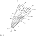
Le dispositif de largage d'eau comprend une cuve 46 close présentant au moins une ouverture 48 pour l'entrée d'eau et au moins une ouverture 50 pour le largage de l'eau vers l'extérieur de l'aéronef. L'ouverture 48 présente une forme permettant à la cuve de s'emmancher sur le ou les tubes 12 de manière à former une connexion étanche de manière connue. Dans le cas de plusieurs tubes parallèles et dans la forme illustrée de deux tubes 12, la cuve présente deux ouvertures 48A, 48B se prolongeant sous forme de manchons 52, 54 permettant la connexion avec les tubes 12. Dans le cas présent, les manchons 52, 54 présentent une forme cylindrique de section circulaire.The water release device comprises a
Dans la forme de réalisation illustrée, la cuve 46 comprend plusieurs ouvertures 50A, 50B ... 50n indépendantes. Les ouvertures 50A, 50B ... 50n sont aboutées l'une à l'autre. Les ouvertures 50A, 50B ... 50n sont contiguës de manière à circonscrire l'ensemble dans une même plus grande ouverture 51 de forme géométrique déterminée par la forme des ouvertures 50A, 50B, ... 50n. Dans la forme illustrée sur les figures, chaque ouverture 50A, 50B ... 50n est de forme rectangulaire. Les ouvertures 50A, 50B ... 50n contiguës sont circonscrites dans une même grande ouverture rectangulaire 51 scindée en plusieurs ouvertures 50A, 50B, ... 50n. Les ouvertures 50A, 50B, ... 50n sont comprises dans un plan parallèle au XY, à savoir un plan perpendiculaire à un plan transversal YZ aux tubes. Les ouvertures 50A, 50B, ... 50n sont orientées de manière à guider les flux s'écoulant au travers vers le sol, à savoir dans une direction verticale Z. En vol, l'aéronef peut voler dans une position cabrée. La porte 6 arrière en position ouverte peut se trouver dans le prolongement du plancher 9 de l'aéronef. Ainsi le dispositif de largage 14 disposée au-delà de la porte 6 mais dans son prolongement longitudinal ne se trouve pas dans une position horizontale en vol. Le plan dans lequel les ouvertures 50A, 50B ... 50n sont disposées est choisi suivant la direction de largage d'eau souhaitée. Par ailleurs, la cuve présente une forme permettant de former des conduits 53A, 53B, ... 53n d'écoulement d'eau dont l'orifice de sortie correspond à chaque ouverture 50A, 50B ... 50n. Les conduits sont ici de forme parallélépipédique de section rectangulaire formant ensemble un bloc parallélépipédique de section rectangulaire dont l'orifice de sortie correspond à l'ouverture 51 rectangulaire. Les contours externes des conduits pourraient être arrondis à des fins aérodynamiques. L'axe de chaque conduit 53A, 53B, ... 53n correspond à l'axe de l'ouverture 50A, 50B ... 50n correspondante.In the illustrated embodiment, the
Selon une forme de réalisation, les ouvertures 50A, 50B ... 50n sont susceptibles chacune d'être obturée par une vanne 55 prenant dans la forme de réalisation illustrée la forme d'un volet respectivement 56A, 56B,... 56n. Selon une forme de réalisation de l'invention, chaque conduit 53A, 53B, ... 53n est pourvu d'un volet 56A, 56B,... 56n. Ainsi, l'ouverture et la fermeture de chaque volet 56A, 56B,... 56n peuvent être contrôlées indépendamment pour chaque volet par un dispositif 58 de contrôle décrit plus loin. Les volets 56 permettent de régler le débit de fluide largué.According to one embodiment, the openings 50A, 50B ... 50n are each capable of being closed by a
Dans la forme de réalisation illustrée, la cuve 46 présente une forme d'entonnoir à savoir dont les dimensions dans un plan parallèle au plan XY diminuent en allant verticalement vers le bas, la dimension la plus grande se trouvant à hauteur des tubes de manière à guider l'eau vers la ou les ouvertures 50. La partie la plus basse de la cuve dans la forme illustrée se trouve être aux dimensions de l'ouverture 51. Les volets 56 se présentent chacun sous la forme d'un panneau plan 60 articulé autour d'un axe parallèle à la direction Y ; l'axe d'articulation est pour chaque panneau central longitudinalement. En position ouverte, les panneaux 60 se trouvent chacun dans un plan parallèle au plan YZ et tous parallèles les uns aux autres. En position fermée, les panneaux 60 sont dans un plan parallèle au plan XY, contiguës, aboutés les uns aux autres sans se superposer obturant chacune l'ouverture 50A, 50B, ... 50n correspondante et fermant l'ouverture rectangulaire 51 susmentionnée. Toute autre forme de réalisation est possible.In the illustrated embodiment, the
Dans la forme illustrée, la cuve 46 présente une dimension dans un plan parallèle au plan YZ diminuant longitudinalement en s'éloignant des ouvertures 48. Toute autre forme de cuve est possible du moment qu'elle présente des ouvertures 48 d'entrée et des ouvertures 50 de sortie permettant le changement de direction du flux pour larguer l'eau dans la direction du feu et en diminuer ainsi sa dispersion.In the form illustrated, the
Selon une forme possible de réalisation, le dispositif de largage 14 est rétractable. En effet, pour permettre à la porte arrière 6 de se fermer, il est nécessaire que le dispositif 14 ne dépasse pas de l'extrémité 20 de la porte arrière. De nombreuses formes de réalisation sont possibles. Selon une première forme possible, le dispositif de largage est lié au tube ou auxdits tubes 12 par l'intermédiaire d'une charnière disposée au plus haut de chacun des tubes 12 et manchons 52, 54 permettant au dispositif de pivoter autour d'un axe transversal parallèle à la direction Y. Un joint périphérique est prévu entre le ou les tubes 12 et le ou les manchons 52, 54 pour assurer l'étanchéité lorsque le ou les manchons sont en position de largage dans le prolongement du ou des tubes 12. Selon une autre forme de réalisation possible, au moins une partie du ou des tubes sont réalisés de manière télescopique pour pouvoir réduire de longueur et permettre au dispositif 14 de largage de ne plus dépasser de l'extrémité 20.According to a possible embodiment, the
Selon une autre forme de réalisation, le dispositif de largage 14 n'est pas rétractable. En effet, il est possible à certains aéronefs hôtes de voler avec la porte arrière 6 ouverte.According to another embodiment, the
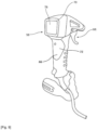
Comme indiqué plus haut, le système 8 est contrôlé à l'aide d'un dispositif de contrôle 58 susceptible d'être manipulé directement par un pilote et/ou un copilote et/ou un troisième homme dans le cockpit et/ou tout autre opérateur dont la fonction est de déclencher le largage d'eau et/ou de préparer la quantité adaptée. Le contrôle pourrait également être envisagé depuis le sol, le dispositif de contrôle étant alors connecté à l'aéronef par tout type de moyen de communication sans fil connu. Le dispositif 58, représenté par un rectangle dans l'aéronef dans l'exemple illustré sur la
Comme montré sur la
Claims (10)
Applications Claiming Priority (1)
| Application Number | Priority Date | Filing Date | Title |
|---|---|---|---|
| FR2208679 | 2022-08-30 |
Publications (1)
| Publication Number | Publication Date |
|---|---|
| EP4331985A1 true EP4331985A1 (en) | 2024-03-06 |
Family
ID=84887938
Family Applications (1)
| Application Number | Title | Priority Date | Filing Date |
|---|---|---|---|
| EP23192069.5A Pending EP4331985A1 (en) | 2022-08-30 | 2023-08-18 | Modular fluid storage and release system and aircraft provided with such a system |
Country Status (3)
| Country | Link |
|---|---|
| US (1) | US20240067338A1 (en) |
| EP (1) | EP4331985A1 (en) |
| CA (1) | CA3209704A1 (en) |
Citations (13)
| Publication number | Priority date | Publication date | Assignee | Title |
|---|---|---|---|---|
| GB497765A (en) * | 1936-06-27 | 1938-12-28 | Marinus Alfred Kjersgaard | Improvements in and relating to flushing tanks |
| US3698480A (en) * | 1971-07-12 | 1972-10-17 | Aero Union Corp | Dual tank air borne fire retardant dispensing system |
| US4195693A (en) * | 1976-04-30 | 1980-04-01 | Messerschmitt-Boelkow-Blohm Gmbh | Device for extinguishing fires from the air |
| FR2610894A1 (en) * | 1987-02-16 | 1988-08-19 | Hercules Europ Center | Method and appliance for projecting a liquid product or the like, or a solid object, from an aircraft |
| CN2483433Y (en) * | 2001-04-05 | 2002-03-27 | 付乃军 | Automatic water storage tank |
| DE102004041774A1 (en) * | 2004-08-28 | 2006-03-02 | Zoltan Von Mohos | Device for receiving and / or dispensing liquids from an aircraft |
| US20060260826A1 (en) * | 2004-01-10 | 2006-11-23 | Hutter Michael D | Portable airborne firefighting and sensing system |
| US7303168B1 (en) * | 2005-02-25 | 2007-12-04 | Lazes Richard J | Aircraft spraying conversion kit for use in extinguishing fires |
| CN102653951A (en) * | 2012-01-11 | 2012-09-05 | 陈万明 | Double-ball flushing water tank |
| US20140224935A1 (en) * | 2013-02-13 | 2014-08-14 | Richard J. Lazes | Aircraft Liquid Dispensing System |
| CN204572050U (en) * | 2015-02-10 | 2015-08-19 | 四川省科建煤炭产业技术研究院有限公司 | A kind of coal mine gas extraction pipeline tailrace |
| EP3929080A1 (en) * | 2020-06-26 | 2021-12-29 | Aeroconseil SA | Fire-fighting device |
| CN216271131U (en) * | 2021-10-28 | 2022-04-12 | 四川中成汇力科技有限公司 | Overflow arrangement is prevented to water tank |
-
2023
- 2023-08-18 US US18/452,164 patent/US20240067338A1/en active Pending
- 2023-08-18 EP EP23192069.5A patent/EP4331985A1/en active Pending
- 2023-08-18 CA CA3209704A patent/CA3209704A1/en active Pending
Patent Citations (13)
| Publication number | Priority date | Publication date | Assignee | Title |
|---|---|---|---|---|
| GB497765A (en) * | 1936-06-27 | 1938-12-28 | Marinus Alfred Kjersgaard | Improvements in and relating to flushing tanks |
| US3698480A (en) * | 1971-07-12 | 1972-10-17 | Aero Union Corp | Dual tank air borne fire retardant dispensing system |
| US4195693A (en) * | 1976-04-30 | 1980-04-01 | Messerschmitt-Boelkow-Blohm Gmbh | Device for extinguishing fires from the air |
| FR2610894A1 (en) * | 1987-02-16 | 1988-08-19 | Hercules Europ Center | Method and appliance for projecting a liquid product or the like, or a solid object, from an aircraft |
| CN2483433Y (en) * | 2001-04-05 | 2002-03-27 | 付乃军 | Automatic water storage tank |
| US20060260826A1 (en) * | 2004-01-10 | 2006-11-23 | Hutter Michael D | Portable airborne firefighting and sensing system |
| DE102004041774A1 (en) * | 2004-08-28 | 2006-03-02 | Zoltan Von Mohos | Device for receiving and / or dispensing liquids from an aircraft |
| US7303168B1 (en) * | 2005-02-25 | 2007-12-04 | Lazes Richard J | Aircraft spraying conversion kit for use in extinguishing fires |
| CN102653951A (en) * | 2012-01-11 | 2012-09-05 | 陈万明 | Double-ball flushing water tank |
| US20140224935A1 (en) * | 2013-02-13 | 2014-08-14 | Richard J. Lazes | Aircraft Liquid Dispensing System |
| CN204572050U (en) * | 2015-02-10 | 2015-08-19 | 四川省科建煤炭产业技术研究院有限公司 | A kind of coal mine gas extraction pipeline tailrace |
| EP3929080A1 (en) * | 2020-06-26 | 2021-12-29 | Aeroconseil SA | Fire-fighting device |
| CN216271131U (en) * | 2021-10-28 | 2022-04-12 | 四川中成汇力科技有限公司 | Overflow arrangement is prevented to water tank |
Also Published As
| Publication number | Publication date |
|---|---|
| US20240067338A1 (en) | 2024-02-29 |
| CA3209704A1 (en) | 2024-02-29 |
Similar Documents
| Publication | Publication Date | Title |
|---|---|---|
| EP3929080A1 (en) | Fire-fighting device | |
| FR2917376A1 (en) | AIRCRAFT AND AIRCRAFT OFFICE FURNITURE COMPRISING SUCH A FURNITURE | |
| FR2817828A1 (en) | Liquid ejection equipment for helicopter comprises liquid reservoir under fuselage with lower concave surface containing liquid evacuation orifices closed and opened by doors | |
| EP1966005B1 (en) | Logistics box | |
| WO2017207942A2 (en) | Cannon turret comprising at least one ammunition magazine, and ammunition container for supplying a magazine of said type | |
| EP4331985A1 (en) | Modular fluid storage and release system and aircraft provided with such a system | |
| FR3065438A1 (en) | MULTIPOSITION AIR INTAKE SYSTEM FOR AN AIRCRAFT | |
| EP4331986A1 (en) | Device for controlling a fluid-dropping system according to at least one parameter criterion for a host fire-fighting aircraft | |
| EP4331984A1 (en) | Device for releasing fluid in a determined direction for host firefighting aircraft and aircraft equipped with such a device | |
| FR2586194A1 (en) | Helicopter-borne firefighting methods and devices and helicopters equipped with these devices | |
| FR3032990A1 (en) | VACUUM MECHANISM FOR A CONCRETE BENCH HAVING A RECEPTACLE FOR LEAKAGE LEAKS | |
| US7303168B1 (en) | Aircraft spraying conversion kit for use in extinguishing fires | |
| EP2014147A1 (en) | Distribution device with an improved storage tank | |
| HUE031495T2 (en) | Fire extinguishing device | |
| EP3002541B1 (en) | Vehicle seat | |
| FR3085819A1 (en) | ARTICULATION OF SPRAY RAMP ARM SEGMENTS | |
| WO2023062290A1 (en) | Firefighting device | |
| EP2397361B1 (en) | Shelf for closing a cavity behind a seat of an automotive vehicle | |
| EP3003791A1 (en) | Mobile partitioning device built into the console of a vehicle | |
| FR2962947A1 (en) | Seat arrangement i.e. second row seat arrangement, for three-row seat motor vehicle, has flap connected to lower part of backrest by tie rod to form quadrangle so that flap is applied against bottom of rear face when backrest is raised | |
| FR2749126A1 (en) | Restocking hopper for seeder attached at rear of tractor, | |
| EP2221231B1 (en) | Transport assembly comprising a trolley and at least two adapted containers | |
| FR3106470A1 (en) | Sprayer for spreading product (s) | |
| FR2662905A1 (en) | Spray apparatus for an agricultural treatment vehicle | |
| FR2610894A1 (en) | Method and appliance for projecting a liquid product or the like, or a solid object, from an aircraft |
Legal Events
| Date | Code | Title | Description |
|---|---|---|---|
| PUAI | Public reference made under article 153(3) epc to a published international application that has entered the european phase |
Free format text: ORIGINAL CODE: 0009012 |
|
| STAA | Information on the status of an ep patent application or granted ep patent |
Free format text: STATUS: REQUEST FOR EXAMINATION WAS MADE |
|
| STAA | Information on the status of an ep patent application or granted ep patent |
Free format text: STATUS: EXAMINATION IS IN PROGRESS |
|
| 17P | Request for examination filed |
Effective date: 20230818 |
|
| AK | Designated contracting states |
Kind code of ref document: A1 Designated state(s): AL AT BE BG CH CY CZ DE DK EE ES FI FR GB GR HR HU IE IS IT LI LT LU LV MC ME MK MT NL NO PL PT RO RS SE SI SK SM TR |
|
| 17Q | First examination report despatched |
Effective date: 20240213 |