EP4331648A2 - Elektronische aerosolbereitstellungssysteme und -verfahren - Google Patents
Elektronische aerosolbereitstellungssysteme und -verfahren Download PDFInfo
- Publication number
- EP4331648A2 EP4331648A2 EP24152605.2A EP24152605A EP4331648A2 EP 4331648 A2 EP4331648 A2 EP 4331648A2 EP 24152605 A EP24152605 A EP 24152605A EP 4331648 A2 EP4331648 A2 EP 4331648A2
- Authority
- EP
- European Patent Office
- Prior art keywords
- aerosol provision
- electronic aerosol
- provision device
- user
- sensor
- Prior art date
- Legal status (The legal status is an assumption and is not a legal conclusion. Google has not performed a legal analysis and makes no representation as to the accuracy of the status listed.)
- Pending
Links
- 239000000443 aerosol Substances 0.000 title claims abstract description 243
- 238000005259 measurement Methods 0.000 claims abstract description 51
- 230000004044 response Effects 0.000 claims abstract description 39
- 238000000034 method Methods 0.000 claims description 25
- 230000000694 effects Effects 0.000 claims description 10
- 238000010438 heat treatment Methods 0.000 claims description 10
- 239000000463 material Substances 0.000 claims description 7
- 230000036772 blood pressure Effects 0.000 claims description 6
- 230000029058 respiratory gaseous exchange Effects 0.000 claims description 6
- 238000004590 computer program Methods 0.000 claims description 5
- 239000002243 precursor Substances 0.000 claims description 3
- 239000003571 electronic cigarette Substances 0.000 description 64
- 238000004891 communication Methods 0.000 description 57
- 239000007788 liquid Substances 0.000 description 30
- 238000010586 diagram Methods 0.000 description 13
- 230000015654 memory Effects 0.000 description 11
- SNICXCGAKADSCV-JTQLQIEISA-N (-)-Nicotine Chemical compound CN1CCC[C@H]1C1=CC=CN=C1 SNICXCGAKADSCV-JTQLQIEISA-N 0.000 description 5
- BZTYNSQSZHARAZ-UHFFFAOYSA-N 2,4-dichloro-1-(4-chlorophenyl)benzene Chemical compound C1=CC(Cl)=CC=C1C1=CC=C(Cl)C=C1Cl BZTYNSQSZHARAZ-UHFFFAOYSA-N 0.000 description 5
- 229960002715 nicotine Drugs 0.000 description 5
- SNICXCGAKADSCV-UHFFFAOYSA-N nicotine Natural products CN1CCCC1C1=CC=CN=C1 SNICXCGAKADSCV-UHFFFAOYSA-N 0.000 description 5
- 238000012545 processing Methods 0.000 description 5
- 239000000758 substrate Substances 0.000 description 5
- 239000003990 capacitor Substances 0.000 description 4
- 230000006870 function Effects 0.000 description 4
- 239000002184 metal Substances 0.000 description 4
- 238000010295 mobile communication Methods 0.000 description 4
- 230000008901 benefit Effects 0.000 description 3
- 239000003086 colorant Substances 0.000 description 3
- 238000007796 conventional method Methods 0.000 description 3
- 230000008878 coupling Effects 0.000 description 3
- 238000010168 coupling process Methods 0.000 description 3
- 238000005859 coupling reaction Methods 0.000 description 3
- 238000009472 formulation Methods 0.000 description 3
- 239000000203 mixture Substances 0.000 description 3
- 230000009471 action Effects 0.000 description 2
- 238000007664 blowing Methods 0.000 description 2
- 230000008859 change Effects 0.000 description 2
- 238000001514 detection method Methods 0.000 description 2
- 238000005516 engineering process Methods 0.000 description 2
- 230000003993 interaction Effects 0.000 description 2
- 230000007246 mechanism Effects 0.000 description 2
- 238000012986 modification Methods 0.000 description 2
- 230000004048 modification Effects 0.000 description 2
- 230000002085 persistent effect Effects 0.000 description 2
- 230000000717 retained effect Effects 0.000 description 2
- 239000004065 semiconductor Substances 0.000 description 2
- 238000004513 sizing Methods 0.000 description 2
- 230000000391 smoking effect Effects 0.000 description 2
- 238000012546 transfer Methods 0.000 description 2
- 238000009834 vaporization Methods 0.000 description 2
- 229920000742 Cotton Polymers 0.000 description 1
- 230000004913 activation Effects 0.000 description 1
- 230000006978 adaptation Effects 0.000 description 1
- 238000013459 approach Methods 0.000 description 1
- 230000004888 barrier function Effects 0.000 description 1
- 230000001419 dependent effect Effects 0.000 description 1
- 230000005669 field effect Effects 0.000 description 1
- 238000001914 filtration Methods 0.000 description 1
- 239000006260 foam Substances 0.000 description 1
- 238000005286 illumination Methods 0.000 description 1
- 230000006698 induction Effects 0.000 description 1
- 239000004973 liquid crystal related substance Substances 0.000 description 1
- 238000007726 management method Methods 0.000 description 1
- 239000011159 matrix material Substances 0.000 description 1
- 230000008450 motivation Effects 0.000 description 1
- 230000003287 optical effect Effects 0.000 description 1
- 230000008569 process Effects 0.000 description 1
- 230000002250 progressing effect Effects 0.000 description 1
- 238000012216 screening Methods 0.000 description 1
- 230000011664 signaling Effects 0.000 description 1
- 239000007787 solid Substances 0.000 description 1
- 239000008275 solid aerosol Substances 0.000 description 1
- 238000006467 substitution reaction Methods 0.000 description 1
- 230000000007 visual effect Effects 0.000 description 1
- 210000000707 wrist Anatomy 0.000 description 1
Images


Classifications
-
- A—HUMAN NECESSITIES
- A24—TOBACCO; CIGARS; CIGARETTES; SIMULATED SMOKING DEVICES; SMOKERS' REQUISITES
- A24F—SMOKERS' REQUISITES; MATCH BOXES; SIMULATED SMOKING DEVICES
- A24F40/00—Electrically operated smoking devices; Component parts thereof; Manufacture thereof; Maintenance or testing thereof; Charging means specially adapted therefor
- A24F40/50—Control or monitoring
-
- A—HUMAN NECESSITIES
- A61—MEDICAL OR VETERINARY SCIENCE; HYGIENE
- A61M—DEVICES FOR INTRODUCING MEDIA INTO, OR ONTO, THE BODY; DEVICES FOR TRANSDUCING BODY MEDIA OR FOR TAKING MEDIA FROM THE BODY; DEVICES FOR PRODUCING OR ENDING SLEEP OR STUPOR
- A61M15/00—Inhalators
- A61M15/06—Inhaling appliances shaped like cigars, cigarettes or pipes
-
- A—HUMAN NECESSITIES
- A24—TOBACCO; CIGARS; CIGARETTES; SIMULATED SMOKING DEVICES; SMOKERS' REQUISITES
- A24B—MANUFACTURE OR PREPARATION OF TOBACCO FOR SMOKING OR CHEWING; TOBACCO; SNUFF
- A24B15/00—Chemical features or treatment of tobacco; Tobacco substitutes, e.g. in liquid form
- A24B15/10—Chemical features of tobacco products or tobacco substitutes
- A24B15/16—Chemical features of tobacco products or tobacco substitutes of tobacco substitutes
- A24B15/167—Chemical features of tobacco products or tobacco substitutes of tobacco substitutes in liquid or vaporisable form, e.g. liquid compositions for electronic cigarettes
-
- A—HUMAN NECESSITIES
- A24—TOBACCO; CIGARS; CIGARETTES; SIMULATED SMOKING DEVICES; SMOKERS' REQUISITES
- A24B—MANUFACTURE OR PREPARATION OF TOBACCO FOR SMOKING OR CHEWING; TOBACCO; SNUFF
- A24B15/00—Chemical features or treatment of tobacco; Tobacco substitutes, e.g. in liquid form
- A24B15/18—Treatment of tobacco products or tobacco substitutes
- A24B15/24—Treatment of tobacco products or tobacco substitutes by extraction; Tobacco extracts
- A24B15/241—Extraction of specific substances
- A24B15/243—Nicotine
-
- A—HUMAN NECESSITIES
- A24—TOBACCO; CIGARS; CIGARETTES; SIMULATED SMOKING DEVICES; SMOKERS' REQUISITES
- A24F—SMOKERS' REQUISITES; MATCH BOXES; SIMULATED SMOKING DEVICES
- A24F40/00—Electrically operated smoking devices; Component parts thereof; Manufacture thereof; Maintenance or testing thereof; Charging means specially adapted therefor
- A24F40/10—Devices using liquid inhalable precursors
-
- A—HUMAN NECESSITIES
- A24—TOBACCO; CIGARS; CIGARETTES; SIMULATED SMOKING DEVICES; SMOKERS' REQUISITES
- A24F—SMOKERS' REQUISITES; MATCH BOXES; SIMULATED SMOKING DEVICES
- A24F40/00—Electrically operated smoking devices; Component parts thereof; Manufacture thereof; Maintenance or testing thereof; Charging means specially adapted therefor
- A24F40/50—Control or monitoring
- A24F40/51—Arrangement of sensors
-
- A—HUMAN NECESSITIES
- A24—TOBACCO; CIGARS; CIGARETTES; SIMULATED SMOKING DEVICES; SMOKERS' REQUISITES
- A24F—SMOKERS' REQUISITES; MATCH BOXES; SIMULATED SMOKING DEVICES
- A24F40/00—Electrically operated smoking devices; Component parts thereof; Manufacture thereof; Maintenance or testing thereof; Charging means specially adapted therefor
- A24F40/60—Devices with integrated user interfaces
-
- A—HUMAN NECESSITIES
- A24—TOBACCO; CIGARS; CIGARETTES; SIMULATED SMOKING DEVICES; SMOKERS' REQUISITES
- A24F—SMOKERS' REQUISITES; MATCH BOXES; SIMULATED SMOKING DEVICES
- A24F40/00—Electrically operated smoking devices; Component parts thereof; Manufacture thereof; Maintenance or testing thereof; Charging means specially adapted therefor
- A24F40/65—Devices with integrated communication means, e.g. Wi-Fi
-
- A—HUMAN NECESSITIES
- A61—MEDICAL OR VETERINARY SCIENCE; HYGIENE
- A61M—DEVICES FOR INTRODUCING MEDIA INTO, OR ONTO, THE BODY; DEVICES FOR TRANSDUCING BODY MEDIA OR FOR TAKING MEDIA FROM THE BODY; DEVICES FOR PRODUCING OR ENDING SLEEP OR STUPOR
- A61M11/00—Sprayers or atomisers specially adapted for therapeutic purposes
- A61M11/04—Sprayers or atomisers specially adapted for therapeutic purposes operated by the vapour pressure of the liquid to be sprayed or atomised
- A61M11/041—Sprayers or atomisers specially adapted for therapeutic purposes operated by the vapour pressure of the liquid to be sprayed or atomised using heaters
- A61M11/042—Sprayers or atomisers specially adapted for therapeutic purposes operated by the vapour pressure of the liquid to be sprayed or atomised using heaters electrical
-
- A—HUMAN NECESSITIES
- A61—MEDICAL OR VETERINARY SCIENCE; HYGIENE
- A61M—DEVICES FOR INTRODUCING MEDIA INTO, OR ONTO, THE BODY; DEVICES FOR TRANSDUCING BODY MEDIA OR FOR TAKING MEDIA FROM THE BODY; DEVICES FOR PRODUCING OR ENDING SLEEP OR STUPOR
- A61M15/00—Inhalators
- A61M15/0001—Details of inhalators; Constructional features thereof
- A61M15/002—Details of inhalators; Constructional features thereof with air flow regulating means
-
- A—HUMAN NECESSITIES
- A61—MEDICAL OR VETERINARY SCIENCE; HYGIENE
- A61M—DEVICES FOR INTRODUCING MEDIA INTO, OR ONTO, THE BODY; DEVICES FOR TRANSDUCING BODY MEDIA OR FOR TAKING MEDIA FROM THE BODY; DEVICES FOR PRODUCING OR ENDING SLEEP OR STUPOR
- A61M16/00—Devices for influencing the respiratory system of patients by gas treatment, e.g. mouth-to-mouth respiration; Tracheal tubes
- A61M16/0003—Accessories therefor, e.g. sensors, vibrators, negative pressure
- A61M2016/0015—Accessories therefor, e.g. sensors, vibrators, negative pressure inhalation detectors
- A61M2016/0018—Accessories therefor, e.g. sensors, vibrators, negative pressure inhalation detectors electrical
- A61M2016/0021—Accessories therefor, e.g. sensors, vibrators, negative pressure inhalation detectors electrical with a proportional output signal, e.g. from a thermistor
-
- A—HUMAN NECESSITIES
- A61—MEDICAL OR VETERINARY SCIENCE; HYGIENE
- A61M—DEVICES FOR INTRODUCING MEDIA INTO, OR ONTO, THE BODY; DEVICES FOR TRANSDUCING BODY MEDIA OR FOR TAKING MEDIA FROM THE BODY; DEVICES FOR PRODUCING OR ENDING SLEEP OR STUPOR
- A61M16/00—Devices for influencing the respiratory system of patients by gas treatment, e.g. mouth-to-mouth respiration; Tracheal tubes
- A61M16/0003—Accessories therefor, e.g. sensors, vibrators, negative pressure
- A61M2016/0015—Accessories therefor, e.g. sensors, vibrators, negative pressure inhalation detectors
- A61M2016/0018—Accessories therefor, e.g. sensors, vibrators, negative pressure inhalation detectors electrical
- A61M2016/0024—Accessories therefor, e.g. sensors, vibrators, negative pressure inhalation detectors electrical with an on-off output signal, e.g. from a switch
-
- A—HUMAN NECESSITIES
- A61—MEDICAL OR VETERINARY SCIENCE; HYGIENE
- A61M—DEVICES FOR INTRODUCING MEDIA INTO, OR ONTO, THE BODY; DEVICES FOR TRANSDUCING BODY MEDIA OR FOR TAKING MEDIA FROM THE BODY; DEVICES FOR PRODUCING OR ENDING SLEEP OR STUPOR
- A61M2205/00—General characteristics of the apparatus
- A61M2205/33—Controlling, regulating or measuring
- A61M2205/3331—Pressure; Flow
-
- A—HUMAN NECESSITIES
- A61—MEDICAL OR VETERINARY SCIENCE; HYGIENE
- A61M—DEVICES FOR INTRODUCING MEDIA INTO, OR ONTO, THE BODY; DEVICES FOR TRANSDUCING BODY MEDIA OR FOR TAKING MEDIA FROM THE BODY; DEVICES FOR PRODUCING OR ENDING SLEEP OR STUPOR
- A61M2205/00—General characteristics of the apparatus
- A61M2205/33—Controlling, regulating or measuring
- A61M2205/3368—Temperature
-
- A—HUMAN NECESSITIES
- A61—MEDICAL OR VETERINARY SCIENCE; HYGIENE
- A61M—DEVICES FOR INTRODUCING MEDIA INTO, OR ONTO, THE BODY; DEVICES FOR TRANSDUCING BODY MEDIA OR FOR TAKING MEDIA FROM THE BODY; DEVICES FOR PRODUCING OR ENDING SLEEP OR STUPOR
- A61M2205/00—General characteristics of the apparatus
- A61M2205/35—Communication
- A61M2205/3546—Range
- A61M2205/3553—Range remote, e.g. between patient's home and doctor's office
-
- A—HUMAN NECESSITIES
- A61—MEDICAL OR VETERINARY SCIENCE; HYGIENE
- A61M—DEVICES FOR INTRODUCING MEDIA INTO, OR ONTO, THE BODY; DEVICES FOR TRANSDUCING BODY MEDIA OR FOR TAKING MEDIA FROM THE BODY; DEVICES FOR PRODUCING OR ENDING SLEEP OR STUPOR
- A61M2205/00—General characteristics of the apparatus
- A61M2205/35—Communication
- A61M2205/3546—Range
- A61M2205/3561—Range local, e.g. within room or hospital
-
- A—HUMAN NECESSITIES
- A61—MEDICAL OR VETERINARY SCIENCE; HYGIENE
- A61M—DEVICES FOR INTRODUCING MEDIA INTO, OR ONTO, THE BODY; DEVICES FOR TRANSDUCING BODY MEDIA OR FOR TAKING MEDIA FROM THE BODY; DEVICES FOR PRODUCING OR ENDING SLEEP OR STUPOR
- A61M2205/00—General characteristics of the apparatus
- A61M2205/35—Communication
- A61M2205/3546—Range
- A61M2205/3569—Range sublocal, e.g. between console and disposable
-
- A—HUMAN NECESSITIES
- A61—MEDICAL OR VETERINARY SCIENCE; HYGIENE
- A61M—DEVICES FOR INTRODUCING MEDIA INTO, OR ONTO, THE BODY; DEVICES FOR TRANSDUCING BODY MEDIA OR FOR TAKING MEDIA FROM THE BODY; DEVICES FOR PRODUCING OR ENDING SLEEP OR STUPOR
- A61M2205/00—General characteristics of the apparatus
- A61M2205/35—Communication
- A61M2205/3576—Communication with non implanted data transmission devices, e.g. using external transmitter or receiver
- A61M2205/3584—Communication with non implanted data transmission devices, e.g. using external transmitter or receiver using modem, internet or bluetooth
-
- A—HUMAN NECESSITIES
- A61—MEDICAL OR VETERINARY SCIENCE; HYGIENE
- A61M—DEVICES FOR INTRODUCING MEDIA INTO, OR ONTO, THE BODY; DEVICES FOR TRANSDUCING BODY MEDIA OR FOR TAKING MEDIA FROM THE BODY; DEVICES FOR PRODUCING OR ENDING SLEEP OR STUPOR
- A61M2205/00—General characteristics of the apparatus
- A61M2205/35—Communication
- A61M2205/3576—Communication with non implanted data transmission devices, e.g. using external transmitter or receiver
- A61M2205/3592—Communication with non implanted data transmission devices, e.g. using external transmitter or receiver using telemetric means, e.g. radio or optical transmission
-
- A—HUMAN NECESSITIES
- A61—MEDICAL OR VETERINARY SCIENCE; HYGIENE
- A61M—DEVICES FOR INTRODUCING MEDIA INTO, OR ONTO, THE BODY; DEVICES FOR TRANSDUCING BODY MEDIA OR FOR TAKING MEDIA FROM THE BODY; DEVICES FOR PRODUCING OR ENDING SLEEP OR STUPOR
- A61M2205/00—General characteristics of the apparatus
- A61M2205/36—General characteristics of the apparatus related to heating or cooling
- A61M2205/3653—General characteristics of the apparatus related to heating or cooling by Joule effect, i.e. electric resistance
-
- A—HUMAN NECESSITIES
- A61—MEDICAL OR VETERINARY SCIENCE; HYGIENE
- A61M—DEVICES FOR INTRODUCING MEDIA INTO, OR ONTO, THE BODY; DEVICES FOR TRANSDUCING BODY MEDIA OR FOR TAKING MEDIA FROM THE BODY; DEVICES FOR PRODUCING OR ENDING SLEEP OR STUPOR
- A61M2205/00—General characteristics of the apparatus
- A61M2205/50—General characteristics of the apparatus with microprocessors or computers
- A61M2205/502—User interfaces, e.g. screens or keyboards
- A61M2205/505—Touch-screens; Virtual keyboard or keypads; Virtual buttons; Soft keys; Mouse touches
-
- A—HUMAN NECESSITIES
- A61—MEDICAL OR VETERINARY SCIENCE; HYGIENE
- A61M—DEVICES FOR INTRODUCING MEDIA INTO, OR ONTO, THE BODY; DEVICES FOR TRANSDUCING BODY MEDIA OR FOR TAKING MEDIA FROM THE BODY; DEVICES FOR PRODUCING OR ENDING SLEEP OR STUPOR
- A61M2205/00—General characteristics of the apparatus
- A61M2205/58—Means for facilitating use, e.g. by people with impaired vision
- A61M2205/581—Means for facilitating use, e.g. by people with impaired vision by audible feedback
-
- A—HUMAN NECESSITIES
- A61—MEDICAL OR VETERINARY SCIENCE; HYGIENE
- A61M—DEVICES FOR INTRODUCING MEDIA INTO, OR ONTO, THE BODY; DEVICES FOR TRANSDUCING BODY MEDIA OR FOR TAKING MEDIA FROM THE BODY; DEVICES FOR PRODUCING OR ENDING SLEEP OR STUPOR
- A61M2205/00—General characteristics of the apparatus
- A61M2205/58—Means for facilitating use, e.g. by people with impaired vision
- A61M2205/582—Means for facilitating use, e.g. by people with impaired vision by tactile feedback
-
- A—HUMAN NECESSITIES
- A61—MEDICAL OR VETERINARY SCIENCE; HYGIENE
- A61M—DEVICES FOR INTRODUCING MEDIA INTO, OR ONTO, THE BODY; DEVICES FOR TRANSDUCING BODY MEDIA OR FOR TAKING MEDIA FROM THE BODY; DEVICES FOR PRODUCING OR ENDING SLEEP OR STUPOR
- A61M2205/00—General characteristics of the apparatus
- A61M2205/58—Means for facilitating use, e.g. by people with impaired vision
- A61M2205/583—Means for facilitating use, e.g. by people with impaired vision by visual feedback
-
- A—HUMAN NECESSITIES
- A61—MEDICAL OR VETERINARY SCIENCE; HYGIENE
- A61M—DEVICES FOR INTRODUCING MEDIA INTO, OR ONTO, THE BODY; DEVICES FOR TRANSDUCING BODY MEDIA OR FOR TAKING MEDIA FROM THE BODY; DEVICES FOR PRODUCING OR ENDING SLEEP OR STUPOR
- A61M2205/00—General characteristics of the apparatus
- A61M2205/60—General characteristics of the apparatus with identification means
- A61M2205/609—Biometric patient identification means
-
- A—HUMAN NECESSITIES
- A61—MEDICAL OR VETERINARY SCIENCE; HYGIENE
- A61M—DEVICES FOR INTRODUCING MEDIA INTO, OR ONTO, THE BODY; DEVICES FOR TRANSDUCING BODY MEDIA OR FOR TAKING MEDIA FROM THE BODY; DEVICES FOR PRODUCING OR ENDING SLEEP OR STUPOR
- A61M2205/00—General characteristics of the apparatus
- A61M2205/82—Internal energy supply devices
- A61M2205/8206—Internal energy supply devices battery-operated
-
- A—HUMAN NECESSITIES
- A61—MEDICAL OR VETERINARY SCIENCE; HYGIENE
- A61M—DEVICES FOR INTRODUCING MEDIA INTO, OR ONTO, THE BODY; DEVICES FOR TRANSDUCING BODY MEDIA OR FOR TAKING MEDIA FROM THE BODY; DEVICES FOR PRODUCING OR ENDING SLEEP OR STUPOR
- A61M2205/00—General characteristics of the apparatus
- A61M2205/82—Internal energy supply devices
- A61M2205/8237—Charging means
- A61M2205/8243—Charging means by induction
-
- A—HUMAN NECESSITIES
- A61—MEDICAL OR VETERINARY SCIENCE; HYGIENE
- A61M—DEVICES FOR INTRODUCING MEDIA INTO, OR ONTO, THE BODY; DEVICES FOR TRANSDUCING BODY MEDIA OR FOR TAKING MEDIA FROM THE BODY; DEVICES FOR PRODUCING OR ENDING SLEEP OR STUPOR
- A61M2209/00—Ancillary equipment
- A61M2209/08—Supports for equipment
- A61M2209/088—Supports for equipment on the body
-
- A—HUMAN NECESSITIES
- A61—MEDICAL OR VETERINARY SCIENCE; HYGIENE
- A61M—DEVICES FOR INTRODUCING MEDIA INTO, OR ONTO, THE BODY; DEVICES FOR TRANSDUCING BODY MEDIA OR FOR TAKING MEDIA FROM THE BODY; DEVICES FOR PRODUCING OR ENDING SLEEP OR STUPOR
- A61M2230/00—Measuring parameters of the user
- A61M2230/005—Parameter used as control input for the apparatus
-
- A—HUMAN NECESSITIES
- A61—MEDICAL OR VETERINARY SCIENCE; HYGIENE
- A61M—DEVICES FOR INTRODUCING MEDIA INTO, OR ONTO, THE BODY; DEVICES FOR TRANSDUCING BODY MEDIA OR FOR TAKING MEDIA FROM THE BODY; DEVICES FOR PRODUCING OR ENDING SLEEP OR STUPOR
- A61M2230/00—Measuring parameters of the user
- A61M2230/04—Heartbeat characteristics, e.g. ECG, blood pressure modulation
- A61M2230/06—Heartbeat rate only
-
- A—HUMAN NECESSITIES
- A61—MEDICAL OR VETERINARY SCIENCE; HYGIENE
- A61M—DEVICES FOR INTRODUCING MEDIA INTO, OR ONTO, THE BODY; DEVICES FOR TRANSDUCING BODY MEDIA OR FOR TAKING MEDIA FROM THE BODY; DEVICES FOR PRODUCING OR ENDING SLEEP OR STUPOR
- A61M2230/00—Measuring parameters of the user
- A61M2230/30—Blood pressure
-
- A—HUMAN NECESSITIES
- A61—MEDICAL OR VETERINARY SCIENCE; HYGIENE
- A61M—DEVICES FOR INTRODUCING MEDIA INTO, OR ONTO, THE BODY; DEVICES FOR TRANSDUCING BODY MEDIA OR FOR TAKING MEDIA FROM THE BODY; DEVICES FOR PRODUCING OR ENDING SLEEP OR STUPOR
- A61M2230/00—Measuring parameters of the user
- A61M2230/40—Respiratory characteristics
- A61M2230/42—Rate
-
- A—HUMAN NECESSITIES
- A61—MEDICAL OR VETERINARY SCIENCE; HYGIENE
- A61M—DEVICES FOR INTRODUCING MEDIA INTO, OR ONTO, THE BODY; DEVICES FOR TRANSDUCING BODY MEDIA OR FOR TAKING MEDIA FROM THE BODY; DEVICES FOR PRODUCING OR ENDING SLEEP OR STUPOR
- A61M2230/00—Measuring parameters of the user
- A61M2230/63—Motion, e.g. physical activity
Definitions
- the present disclosure relates to electronic aerosol provision systems such as nicotine delivery systems (e.g. electronic cigarettes and the like) and associated functionality.
- nicotine delivery systems e.g. electronic cigarettes and the like
- Electronic aerosol provision devices such as electronic cigarettes (e-cigarettes) generally contain a reservoir of a source formulation, typically a liquid including nicotine which is sometimes referred to as an e-liquid, from which an aerosol is generated, e.g. through heat vaporisation.
- An aerosol source for an aerosol provision device may thus comprise a heater having a heating element arranged to receive source liquid from the reservoir, for example through wicking / capillary action. While a user inhales on the device, electrical power is supplied to the heating element to vaporise source liquid in the vicinity of the heating element to generate an aerosol for inhalation by the user. The amount of power supplied to the heating element may in some cases be varied to control aspects of the aerosol generation.
- the devices are usually provided with one or more air inlet holes located away from a mouthpiece end of the system.
- air is drawn in through the inlet holes and past the aerosol source so that vapour from the aerosol source becomes entrained in the airflow with the resulting aerosol being inhaled by the user.
- vaping The practice of inhaling vaporised liquid in this manner is commonly referred to as vaping.
- An e-cigarette may have an interface to support external data communications.
- This interface may be used, for example, to communicate with a computing device running a software application associated with the use of the e-cigarette.
- the computing device may comprise a smart phone or tablet computer running an application ("app") provided to facilitate a user's interaction with the e-cigarette.
- the communications interface may be used, for example, to load control parameters and/or updated software onto the e-cigarette.
- the interface may be utilised to download data from the e-cigarette to the computing device, for example for display to a user though the user interface of an app running on the computing device.
- the downloaded data may, for example, represent usage parameters of the e-cigarette, fault conditions, etc.
- many other forms of data can be exchanged between an e-cigarette and one or more external devices.
- a system comprising: an electronic aerosol provision device for selectively providing an aerosol to a user of the electronic aerosol provision device; a computing device configured to communicate with the electronic aerosol provision device to exchange operating data associated with the operation of the electronic aerosol provision device; and a biometric sensor configured to measure a biometric parameter of the user of the electronic aerosol provision device and to communicate with the computing device to exchange sensor data indicating a measurement of the biometric parameter; and wherein the computing device is configured to control an aspect of its operation relating to the electronic aerosol provision device in response to the sensor data received from the biometric sensor.
- a method of operating a system comprising an electronic aerosol provision device, a computing device configured to communicate with the electronic aerosol provision device to exchange operating data associated with the operation of the electronic aerosol provision device, and a biometric sensor configured to measure a biometric parameter of a user of the electronic aerosol provision device and to communicate with the computing device to exchange sensor data indicating a measurement of the biometric parameter; wherein the method comprises: the biometric sensor measuring a biometric parameter of a user of the electronic aerosol provision device and communicating sensor data indicating a measurement of the biometric parameter to the computing device; and the computing device controlling an aspect of its operation relating to the electronic aerosol provision device in response to the sensor data received from the biometric sensor.
- a computing device configured to communicate with an electronic aerosol provision device to exchange operating data associated with the operation of the electronic aerosol provision device and to communicate with a biometric sensor to receive sensor data from the biometric sensor indicating a measurement of a biometric parameter of a user of the electronic aerosol provision device, wherein the computing device is further configured to control an aspect of its operation relating to the electronic aerosol provision device in response to the sensor data received from the biometric sensor.
- a method of operating a computing device configured to communicate with an electronic aerosol provision device to exchange operating data associated with the operation of the electronic aerosol provision device, the method comprising communicating with a biometric sensor to receive sensor data from the biometric sensor indicating a measurement of a biometric parameter of a user of the electronic aerosol provision device and controlling an aspect of the computing device's operation relating to the electronic aerosol provision device in response to the sensor data received from the biometric sensor.
- a computer program product comprising machine readable instructions which when executed on a computing device configure the computing device to communicate with an electronic aerosol provision device to exchange operating data associated with the operation of the electronic aerosol provision device, to communicate with a biometric sensor to receive sensor data from the biometric sensor indicating a measurement of a biometric parameter of a user of the electronic aerosol provision device, and to control an aspect of the computing device's operation relating to the electronic aerosol provision device in response to the sensor data received from the biometric sensor.
- a system comprising: electronic aerosol provision means for selectively providing an aerosol to a user of the electronic aerosol provision means; computing means for communicating with the electronic aerosol provision means to exchange operating data associated with the operation of the electronic aerosol provision means; and biometric sensor means for measuring a biometric parameter of the user of the electronic aerosol provision means and communicating with the computing means to exchange sensor data indicating a measurement of the biometric parameter; and wherein the computing means controls an aspect of its operation relating to the electronic aerosol provision means in response to the sensor data received from the biometric means.
- an aerosol provision device such as an e-cigarette.
- e-cigarette a device that provides aerosol to an aerosol.
- aerosol provision device such as an e-cigarette.
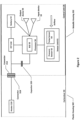
- FIG. 1 is a schematic (exploded) diagram of an e-cigarette 10 in accordance with some embodiments of the disclosure (not to scale).
- the e-cigarette comprises a body or control unit 20 and a cartomiser 30.
- the cartomiser 30 includes a reservoir 38 of liquid, typically including a liquid and nicotine and / or flavouring, a heater 36, and a mouthpiece 35.
- the e-cigarette 10 in this example has a longitudinal or cylindrical axis which extends along a centre-line of the e-cigarette from the mouthpiece 35 at one end of the cartomiser 30 to an opposing end of the control unit 20 (usually referred to as the tip end). This longitudinal axis is indicated in Figure 1 by the dashed line denoted LA.
- the liquid reservoir 38 in the cartomiser may hold the (e-)liquid directly in free liquid form, or may utilise some absorbing structure, such as a foam matrix or cotton material, etc., as a retainer for the liquid.
- the liquid is then fed from the reservoir 38 to be delivered to a vaporiser comprising the heater 36.
- liquid may flow via capillary action from the reservoir 38 to the heater 36 via a wick (not shown in Figure 1 ).
- the control unit 20 includes a re-chargeable cell or battery 54 to provide power to the e-cigarette 10 (referred to hereinafter as a battery) and a printed circuit board (PCB) 28 and/or other electronics for generally controlling the e-cigarette.
- a re-chargeable cell or battery 54 to provide power to the e-cigarette 10 (referred to hereinafter as a battery) and a printed circuit board (PCB) 28 and/or other electronics for generally controlling the e-cigarette.
- PCB printed circuit board
- control unit 20 and the cartomiser 30 are in this example detachable from one another, as shown in Figure 1 , but are joined together when the device 10 is in use, for example, by a screw or bayonet fitting.
- the connectors on the cartomiser 30 and the control unit 20 are indicated schematically in Figure 1 as 31B and 21A respectively. This connection between the control unit and cartomiser provides for mechanical and electrical connectivity between the two.
- the electrical connection 21A on the control unit that is used to connect to the cartomiser may also serve as a socket for connecting a charging device (not shown).
- the other end of this charging device can be plugged into a USB socket to re-charge the battery 54 in the control unit of the e-cigarette.
- the e-cigarette may be provided (for example) with a cable for direct connection between the electrical connection 21A and a USB socket.
- the control unit is provided with one or more holes for air inlet adjacent to PCB 28. These holes connect to an air passage through the control unit to an air passage provided through the connector 21A. This then links to an air path through the cartomiser 30 to the mouthpiece 35.
- the heater 36 and the liquid reservoir 38 are configured to provide an air channel between the connector 31B and the mouthpiece 35. This air channel may flow through the centre of the cartomiser 30, with the liquid reservoir 38 confined to an annular region around this central path. Alternatively (or additionally) the airflow channel may lie between the liquid reservoir 38 and an outer housing of the cartomiser 30.
- the e-cigarette 10 shown in Figure 1 is presented by way of example only, and many other implementations may be adopted.
- the cartomiser 30 is split into a cartridge containing the liquid reservoir 38 and a separate vaporiser portion containing the heater 36.
- the cartridge may be disposed of after the liquid in reservoir 38 has been exhausted, but the separate vaporiser portion containing the heater 36 is retained.
- an e-cigarette may be provided with a cartomiser 30 as shown in Figure 1 , or else constructed as a one-piece (unitary) device, but the liquid reservoir 38 is in the form of a (user-)replaceable cartridge and / or the liquid reservoir may be user-refillable.
- the heater 36 may be located at the opposite end of the cartomiser 30 from that shown in Figure 1 , i.e. between the liquid reservoir 38 and the mouthpiece 35, or else the heater 36 is located along a central axis LA of the cartomiser, and the liquid reservoir is in the form of an annular structure which is radially outside the heater 35.
- control unit 20 airflow may enter the control unit at the tip end, i.e. the opposite end to connector 21A, in addition to or instead of the airflow adjacent to PCB 28. In this case the airflow would typically be drawn towards the cartomiser along a passage between the battery 54 and the outer wall of the control unit.
- control unit may comprise a PCB located on or near the tip end, e.g. between the battery and the tip end. Such a PCB may be provided in addition to or instead of PCB 28.
- an e-cigarette may support charging at the tip end, or via a socket elsewhere on the device, in addition to or in place of charging at the connection point between the cartomiser and the control unit.
- some e-cigarettes are provided as essentially integrated units, in which case a user is unable to disconnect the cartomiser from the control unit).
- Other e-cigarettes may also support wireless (induction) charging, in addition to (or instead of) wired charging.
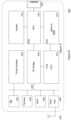
- Figure 2 is a schematic diagram of the main functional components of the e-cigarette 10 of Figure 1 in accordance with some embodiments of the disclosure. It will be recognised that Figure 2 is primarily concerned with electrical connectivity and functionality and is not intended to indicate the physical sizing of the different components, nor details of their physical placement within the control unit 20 or cartomiser 30. In addition, it will be appreciated that at least some of the components shown in Figure 2 located within the control unit 20 may be mounted on the circuit board 28. Alternatively, one or more of such components may instead be accommodated in the control unit to operate in conjunction with the circuit board 28, but not physically mounted on the circuit board itself. For example, these components may be located on one or more additional circuit boards, or they may be separately located (such as battery 54).
- the cartomiser contains heater 310 which receives power through connector 31B.
- the control unit 20 includes an electrical socket or connector 21A for connecting to the corresponding connector 31B of the cartomiser 30 (or potentially to a USB charging device). This then provides electrical connectivity between the control unit 20 and the cartomiser 30.
- the control unit 20 further includes a sensor unit 61, which is located in or adjacent to the air path through the control unit 20 from the air inlet(s) to the air outlet (to the cartomiser 30 through the connector 21A).
- the sensor unit contains a pressure sensor 62 and temperature sensor 63 (also in or adjacent to this air path).
- the control unit further includes a capacitor 220, a processor 50, a field effect transistor (FET) switch 210, a battery 54, and input and output devices 59, 58.
- FET field effect transistor
- the operations of the processor 50 and other electronic components, such as the pressure sensor 62, are generally controlled at least in part by software programs running on the processor (or other components). Such software programs may be stored in non-volatile memory, such as ROM, which can be integrated into the processor 50 itself, or provided as a separate component.
- the processor 50 may access the ROM to load and execute individual software programs as and when required.
- the processor 50 also contains appropriate communications facilities, e.g. pins or pads (plus corresponding control software), for communicating as appropriate with other devices in the control unit 20, such as the pressure sensor 62.
- the output device(s) 58 may provide visible, audio and/or haptic output.
- the output device(s) may include a speaker 58, a vibrator, and/or one or more lights.
- the lights are typically provided in the form of one or more light emitting diodes (LEDs), which may be the same or different colours (or multi-coloured). In the case of multi-coloured LEDs, different colours are obtained by switching different coloured, e.g. red, green or blue, LEDs on, optionally at different relative brightness to give corresponding relative variations in colour.
- LEDs light emitting diodes
- the output from the output device may be used to signal to the user various conditions or states within the e-cigarette, such as a low battery warning.
- Different output signals may be used for signalling different states or conditions.
- the output device 58 is an audio speaker
- different states or conditions may be represented by tones or beeps of different pitch and/or duration, and/or by providing multiple such beeps or tones.
- the output device 58 includes one or more lights
- different states or conditions may be represented by using different colours, pulses of light or continuous illumination, different pulse durations, and so on.
- one indicator light might be utilised to show a low battery warning, while another indicator light might be used to indicate that the liquid reservoir 58 is nearly depleted.
- a given e-cigarette may include output devices to support multiple different output modes (audio, visual etc.).
- the input device(s) 59 may be provided in various forms.
- an input device (or devices) may be implemented as buttons on the outside of the e-cigarette - e.g. as mechanical, electrical or capacitive (touch) sensors.
- Some devices may support blowing into or sucking on the e-cigarette as an input mechanism (such blowing / sucking may be detected by pressure sensor 62, which would then be also acting as a form of input device 59), and/or connecting/disconnecting the cartomiser 30 and control unit 20 as another form of input mechanism.
- a given e-cigarette may include input devices 59 to support multiple different input modes.
- the e-cigarette 10 provides an air path from the air inlet through the e-cigarette, past the pressure sensor 62 (or past an opening to an air channel leading to the pressure sensor) and the heater 310 in the cartomiser 30 to the mouthpiece 35.
- the processor 50 detects such inhalation based on information from the pressure sensor 62.
- the CPU supplies power from the battery 54 to the heater, which thereby heats and vaporises the nicotine from the liquid reservoir 38 for inhalation by the user.
- a FET 210 is connected between the battery 54 and the connector 21A.
- This FET 210 acts as a switch.
- the processor 50 is connected to the gate of the FET to operate the switch, thereby allowing the processor to switch on and off the flow of power from the battery 54 to heater 310 according to the status of the detected airflow.
- the heater current can be relatively large, for example, in the range 1-5 amps, and hence the FET 210 should be implemented to support such current control (likewise for any other form of switch that might be used in place of FET 210).
- a pulse-width modulation (PWM) scheme may be adopted.
- a PWM scheme may be based on a repetition period of say 1ms. Within each such period, the switch 210 is turned on for a proportion of the period, and turned off for the remaining proportion of the period. This is parameterised by a duty cycle, whereby a duty cycle of 0 indicates that the switch is off for all of each period (i.e.
- a duty cycle of 0.33 indicates that the switch is on for a third of each period
- a duty cycle of 0.66 indicates that the switch is on for two-thirds of each period
- a duty cycle of 1 indicates that the FET is on for all of each period (i.e. in effect, permanently on). It will be appreciated that these are only given as example settings for the duty cycle, and intermediate values can be used as appropriate.
- the use of PWM provides an effective power to the heater which is given by the nominal available power (based on the battery output voltage and the heater resistance) multiplied by the duty cycle.
- the processor 50 may, for example, utilise a duty cycle of 1 (i.e. full power) at the start of an inhalation to initially raise the heater 310 to its desired operating temperature as quickly as possible. Once this desired operating temperature has been achieved, the processor 50 may then reduce the duty cycle to some suitable value in order to supply the heater 310 with the desired operating power.
- the processor 50 includes a communications interface 55 for wireless communications, in particular in this example, support for Bluetooth ® Low Energy (BLE) communications.
- BLE Bluetooth ® Low Energy
- the heater 310 may be utilised as an antenna for use by the communications interface 55 for transmitting and receiving the wireless communications.
- the control unit 20 may have a metal housing 202, whereas the cartomiser portion 30 may have a plastic housing 302 (reflecting the fact that the cartomiser 30 is disposable, whereas the control unit 20 is retained and therefore may benefit from being more durable).
- the metal housing acts as a screen or barrier which can affect the operation of an antenna located within the control unit 20 itself.
- utilising the heater 310 as the antenna for the wireless communications can help to avoid this metal screening because of the plastic housing of the cartomiser, but without adding additional components or complexity (or cost) to the cartomiser.
- a separate antenna may be provided (not shown), or a portion of the metal housing may be used.
- the processor 50 may be coupled to the power line from the battery 54 to the heater 310 (via connector 31B) by a capacitor 220.
- This capacitive coupling occurs downstream of the switch 210, since the wireless communications may operate when the heater is not powered for heating (as discussed in more detail below). It will be appreciated that capacitor 220 helps prevent the power supply from the battery 54 to the heater 310 being diverted back to the processor 50.
- the capacitive coupling may be implemented using a more complex LC (inductor-capacitor) network, which can also provide impedance matching with the output of the communications interface 55.
- this impedance matching can help support proper transfer of signals between the communications interface 55 and the heater 310 acting as the antenna, rather than having such signals reflected back along the connection).
- the processor 50 and communications interface are implemented using a Dialog DA14580 chip from Dialog Semiconductor PLC, based in Reading, United Kingdom. Further information (and a data sheet) for this chip is available, for example, at: http://www.dialog-semiconductor.com/products/bluetooth-smart/smartbond-da14580.
- FIG 3 presents a high-level and simplified overview of this chip 50, including the communications interface 55 for supporting Bluetooth ® Low Energy.
- This interface includes in particular a radio transceiver 520 for performing signal modulation and demodulation, etc, link layer hardware 512, and an advanced encryption facility (128 bits) 511.
- the output from the radio transceiver 520 is connected to the antenna (for example, to the heater 310 acting as the antenna via capacitive coupling 220 and connectors 21A and 31B).
- the processor 50 further includes a general processing core 530, RAM 531, ROM 532, a one-time programming (OTP) unit 533, a general purpose I/O system 560 (for communicating with other components on the PCB 28), a power management unit 540 and a bridge 570 for connecting two buses.
- Software instructions stored in the ROM 532 and/or OTP unit 533 may be loaded into RAM 531 (and/or into memory provided as part of core 530) for execution by one or more processing units within core 530.
- These software instructions cause the processor 50 to implement functionality as described herein, such as interfacing with the sensor unit 61 and controlling the heater accordingly.
- the device shown in Figure 3 acts as both a communications interface 55 and also as a general controller for the electronic vapour provision device 10, in other embodiments these two functions may be split between two or more different devices (chips) - e.g. one chip may serve as the communications interface 55, and another chip as the general controller for the electronic vapour provision device 10.
- chips devices
- the processor 50 may be configured to prevent wireless communications when the heater is being used for vaporising liquid from reservoir 38. For example, wireless communications may be suspended, terminated or prevented from starting when switch 210 is switched on. Conversely, if wireless communications are ongoing, then activation of the heater may be prevented - e.g. by disregarding a detection of airflow from the sensor unit 61, and/or by not operating switch 210 to turn on power to the heater 310 while the wireless communications are progressing.
- One reason for preventing the simultaneous operation of heater 310 for both heating and wireless communications in some implementations is to help avoid potential interference from the PWM control of the heater.
- This PWM control has its own frequency (based on the repetition frequency of the pulses), albeit typically much lower than the frequency used for the wireless communications, and the two could potentially interfere with one another. In some situations, such interference may not, in practice, cause any problems, and simultaneous operation of heater 310 for both heating and wireless communications may be allowed (if so desired). This may be facilitated, for example, by techniques such as the appropriate selection of signal strengths and/or PWM frequency, the provision of suitable filtering, etc.
- FIG. 4 is a schematic diagram showing a system 600 supporting Bluetooth ® Low Energy communications between an e-cigarette 10, a smart phone 400 and a biometric sensor 800 arranged to measure a biometric parameter, such as a heart rate, of a user of the e-cigarette.
- a biometric parameter such as a heart rate
- the smart phone 400 also supports wireless communications with the biometric sensor 800 for obtaining information regarding measurements of a biometric parameter for a user of the e-cigarette.
- Communications between the e-cigarette 10 and the smart phone / computing device 400 can be used to support a wide range of functions, for example, to upgrade firmware on the e-cigarette 10, to retrieve usage and/or diagnostic data from the e-cigarette 10, to reset or unlock the e-cigarette 10, to control settings on the e-cigarette, etc.
- the e-cigarette 10 when the e-cigarette 10 is switched on, such as by using input device 59, or possibly by joining the cartomiser 30 to the control unit 20, it starts to advertise for Bluetooth ® Low Energy communication. If this outgoing communication is received by smart phone 400, then the smart phone 400 requests a connection to the e-cigarette 10. The e-cigarette may notify this request to a user via output device 58, and wait for the user to accept or reject the request via input device 59. Assuming the request is accepted, the e-cigarette 10 is able to communicate further with the smart phone 400. Note that the e-cigarette may remember the identity of smart phone 400 and be able to accept future connection requests automatically from that smart phone.
- the smart phone 400 and the e-cigarette 10 operate in a client-server mode, with the smart phone operating as a client that initiates and sends requests to the e-cigarette which therefore operates as a server (and responds to the requests as appropriate).
- a Bluetooth ® Low Energy link (also known as Bluetooth Smart ® ) implements the IEEE 802.15.1 standard, and operates at a frequency of 2.4-2.5 GHz, corresponding to a wavelength of about 12cm, with data rates of up to 1 Mbit/s.
- the set-up time for a connection is less than 6ms, and the average power consumption can be very low - of the order 1 mW or less.
- a Bluetooth Low Energy link may extend up to some 50m. However, for the situation shown in Figure 4 , the e-cigarette 10 and the smart phone 400 will typically belong to the same person, and will therefore be in much closer proximity to one another - e.g. 1m. Further information about Bluetooth Low Energy can be found in the relevant operating standard documents and also, for example, at http://www.bluetooth.com/Pages/Bluetooth-Smart.aspx.
- e-cigarette 10 may support other communications protocols for communication with smart phone 400 (or any other appropriate device).
- Such other communications protocols may be instead of, or in addition to, Bluetooth Low Energy.
- Examples of such other communications protocols include Bluetooth ® (not the low energy variant), see for example, www.bluetooth.com, near field communications (NFC), as per ISO 13157, and WiFi ® .
- NFC communications operate at much lower wavelengths than Bluetooth (13.56 MHz) and generally have a much shorter range - say ⁇ 0.2m. However, this short range is still compatible with most usage scenarios such as shown in Figure 4 .
- low-power WiFi ® communications such as IEEE802.11ah, IEEE802.11v, or similar, may be employed between the e-cigarette 10 and a remote device.
- a suitable communications chipset may be included on PCB 28, either as part of the processor 50 or as a separate component. The skilled person will be aware of other wireless communication protocols that may be employed in e-cigarette 10.
- the e-cigarette 10 can communicate with a mobile communication device 400, for example by pairing the devices using the Bluetooth ® low energy protocol so that it is possible to provide additional functionality for a user of the electronic cigarette 10 and the smart phone 400, by providing suitable software instructions (for example in the form of an app) to run on the smart phone.
- FIG. 5 is a schematic diagram of the main functional components of the biometric sensor 800 of Figure 4 .
- the biometric sensor 800 is a heart rate monitor configured to measure the heart rate of a user.
- the biometric sensor may instead, or additionally, comprise a blood pressure sensor for measuring a user's blood pressure, a breathing rate sensor for measuring a user's breathing rate, and / or a user activity sensor for measuring an aspect of a user's activity.
- the biometric sensor 800 may be based on conventional biometric sensor hardware that may be configured to operate in a system providing the functionality described herein. It will be appreciated the biometric sensor 800, and indeed the elements represented in all the other figures described herein, will in practice comprise further components (e.g.
- the biometric sensor 800 comprises a biometric sensing element 802, a central processing unit (CPU) 808, a transceiver unit 804 and an antenna 806.
- the CPU 808 is configured to communicate with the biometric sensing element 802 and transceiver 804 over a communications bus in accordance with conventional techniques.
- the biometric sensing element 802 is configured to measure a biometric parameter of a user, i.e. in this example a heart rate, and it may do this in accordance with conventional techniques.
- the biometric sensor 800 may comprise a watch-like device to be worn on a user's wrist with heart rate measuring functionality.
- the biometric sensor 800 may adopt similar techniques to those used in conventional heart rate monitors supporting wireless communications functionality.
- the CPU 808 is configured to receive measurements of the user's heart rate from the biometric sensing element 802 and to control the transceiver unit 804 to wirelessly transmit an indication of the biometric measurement(s) to the smart phone 400 using the antenna 806.
- the communications between the biometric sensor 800 and the smart phone 400 may be configured and operate in accordance with conventional wireless communications techniques, for example in accordance with one or more of the many established protocols for wireless communications, such as Bluetooth ® (standard or low-energy variants), near field communication and Wi-Fi ® as described previously, and also phone based communication such as 2G, 3G and/or 4G.
- wireless communications such as Bluetooth ® (standard or low-energy variants), near field communication and Wi-Fi ® as described previously, and also phone based communication such as 2G, 3G and/or 4G.
- the biometric sensor 800 can communicate with the mobile communication device 400, for example by pairing using the Bluetooth ® low energy protocol, so that it is possible to provide the system with additional functionality that takes account of biometric measurements for a user of the electronic cigarette 10 and the smart phone 400, by providing suitable software instructions (for example in the form of an app) to run on the smart phone.
- FIG. 6 is a schematic diagram of the main functional components of the smart phone 400 of Figure 4 in accordance with some embodiments of the disclosure. It will be recognised that as for the other figures described herein, Figure 6 is not intended to indicate the physical sizing of the different components, nor details of their relative physical placements.
- the smart phone 400 may comprise conventional smart phone hardware which is configured to operate to provide the functionality described herein by running a suitably programmed software application (app).
- the smart phone 400 comprises a central processing unit (CPU) (410) which may communicate with components of the smart phone either through direct connections or via an I/O bridge 414 and/or a bus 430 as applicable.
- CPU central processing unit
- the CPU communicates directly with a memory 412, which may comprise a persistent memory such as for example Flash ® memory for storing an operating system and applications (apps), and volatile memory such as RAM for holding data currently in use by the CPU.
- a persistent memory such as for example Flash ® memory for storing an operating system and applications (apps)
- volatile memory such as RAM for holding data currently in use by the CPU.
- persistent and volatile memories are formed by physically distinct units (not shown).
- the memory may separately comprise plug-in memory such as a microSD card, and also subscriber information data on a subscriber information module (SIM) (not shown).
- SIM subscriber information module
- the smart phone may also comprise a graphics processing unit (GPU) 416.
- the GPU may communicate directly with the CPU or via the I/O bridge, or may be part of the CPU.
- the GPU may share RAM with the CPU or may have its own dedicated RAM (not shown) and is connected to the display 418 of the mobile phone.
- the display is typically a liquid crystal (LCD) or organic light-emitting diode (OLED) display, but may be any suitable display technology, such as e-ink.
- the GPU may also be used to drive one or more loudspeakers 420 of the smart phone.
- the speaker may be connected to the CPU via the I/O bridge and the bus.
- Other components of the smart phone may be similarly connected via the bus, including a touch surface 432 such as a capacitive touch surface overlaid on the screen for the purposes of providing a touch input to the device, a microphone 434 for receiving speech from the user, one or more cameras 436 for capturing images, a global positioning system (GPS) unit 438 for obtaining an estimate of the smart phone's geographical position, and wireless communication means 440 (i.e. a transceiver).
- GPS global positioning system
- the wireless communication means 440 may in turn comprise several separate wireless communication systems adhering to different standards and/or protocols, such as Bluetooth ® (standard or low-energy variants), near field communication and Wi-Fi ® as described previously, and also phone based communication such as 2G, 3G and/or 4G.
- Bluetooth ® standard or low-energy variants
- Wi-Fi ® wireless fidelity
- the systems are typically powered by a battery (not shown) that may be chargeable via a power input (not shown) that in turn may be part of a data link such as USB (not shown).
- smart phones may include different features (for example a compass or a buzzer) and may omit some of those listed above (for example a touch surface).
- a computing device such as smart phone 400 may comprise a CPU and a memory for storing and running an app to provide functionality in accordance with the principles described herein.
- a system which comprises an electronic aerosol provision device (e.g. an e-cigarette) for selectively providing an aerosol to a user of the electronic aerosol provision device, a biometric sensor (e.g. a heart rate monitor) for measure a biometric parameter (e.g. a heart rate) of the user of the electronic aerosol provision device, and a computing device (e.g. a smartphone) configured to communicate with the electronic aerosol provision device and the biometric sensor.
- an electronic aerosol provision device e.g. an e-cigarette
- a biometric sensor e.g. a heart rate monitor
- a computing device e.g. a smartphone
- the computing device may run a software program (i.e. an application / app) to configure the computing device to communicate with the electronic aerosol provision device to exchange operating data associated with the operation of the electronic aerosol provision device.
- the operating data relating to the aerosol provision device may comprise, for example, usage statistics transferred from the aerosol provision device to the computing device relating to the use of the aerosol provision device. This usage data may be presented to a user through a user interface of the app running on the computing device. Alternatively, or in addition, the operating data may comprise control (configuration) information transferred from the computing device to the aerosol provision device to control an aspect of the operation of the aerosol provision device.
- control information may be arranged to modify an operational settings for the aerosol provision device, for example a power supply level for a heater of the aerosol device.
- Control information transferred to the aerosol the device from the computing device may be generated in response to user input through the user interface of the computing device and / or may be automatically generated by the computing device itself in response to particular conditions.
- the software program / app running on the computing device that configures the computing device to support communications with the electronic aerosol provision device also configures the computing device to support communications with the biometric sensor, and in particular to allow the computing device to receive and process sensor data from the biometric sensor comprising an indication of one or more measurements of one or more biometric parameters of a user of the electronic aerosol provision device.
- the computing device in this example is further configured to control an aspect of its operation, and in particular an aspect of its operation relating to the electronic aerosol provision device, in response to the sensor data received from the biometric sensor.
- Figure 7 is a flow diagram schematically showing steps of a method of operating the system 600 schematically represented in Figure 4 in accordance with an embodiment of the disclosure.
- a software application (app) relating to the electronic aerosol provision device is launched on the computing device.
- This app may be provided by the manufacturer / vendor of the electronic aerosol provision device, or may be provided independently by another party.
- the app may provide a range of functionality associated with / relating to the electronic aerosol provision device, for example including functionality of the kind provided with known apps relating to electronic aerosol provision devices.
- the app may in some implementations cause the computing device to provide a user interface through which a user can view operating data associated with the aerosol provision device, for example frequency and times of use over a previous time period, as well as status information for the aerosol provision device, for example a battery level or power setting.
- the app may also allow the user to control one or more operational aspects of the electronic aerosol provision device, for example setting a nominal power level for a heater of the device, through the user interface provided by the computing device. It will be appreciated the app may be written / created to provide the functionality described herein using conventional programming techniques.
- step S102 of the example represented in Figure 7 operating data associated with the operation of the electronic aerosol provision device is communicated from the electronic aerosol provision device to the computing device for display to the user through the user interface provided by the app running on the computing device.
- this operating data may, for example, comprise an indication of previous usage and or status information relating to the electronic aerosol provision device.
- step S103 the biometric sensor measures a biometric parameter, e.g. heart rate, of the user of the electronic aerosol provision device. As noted above, this may be performed in accordance with conventional biometric sensing techniques.
- a biometric parameter e.g. heart rate
- step S104 the biometric sensor communicates sensor data to the computing device which indicates a measurement of the relevant biometric parameter.
- the communication and data coding protocols associated with the transfer of information between the various elements of the system may be performed in accordance with established wireless communication techniques.
- step S105 after having received the indication of the measurement of the biometric parameter from the biometric sensor, the computing device is configured to control an aspect of its operation relating to the electronic aerosol provision device in response to the sensor data.
- the computing device may control an aspect of its operation in response to the sensor data.
- the step of the computing device controlling an aspect of its operation may involve the computing device updating a user interface to provide a user with information relating to the measurement of the biometric parameter associated with the sensor data, i.e. to provide a user with feedback relating to the biometric measurement(s).
- the computing device may be configured to include an indication of the measurement of a relevant biometric parameter within through the user interface presented to the user in association with the aerosol provision device.
- a user may observe any effect the use of the electronic aerosol provision device has on the relevant biometric parameter. This may be of general interest to the user, and may furthermore allow the user to take account of the measurement of the biometric parameter in deciding how to proceed with using the electronic aerosol provision device.
- the user may elect to limit their use of the aerosol system for a period of time. This may be done by the user ceasing use or reducing an amount of aerosol generated by the aerosol provision device during use, for example by limiting the power supply to a heater of the aerosol provision device.
- the control may be provided through user input through the user interface of the computing device.
- the computing device may be configured to present the user with a value directly corresponding to the measurement of the biometric parameter, for example a value of the user's heart rate in terms of beats per minute.
- the computing device may be configured to present the user, through the user interface, with an indication as to whether the biometric parameter falls within a particular predefined range, for example a preferred range or a less preferred range.
- a preferred range or a less preferred range may be based on established medical opinions for the relevant biometric parameter.
- an indication may be raised in the user interface. The indication may be provided in many ways, for example by sounding an audible signal or modifying the appearance of the display, for example changing the colour or including a specific logo.
- the computing device may be configured to communicate an indication of the sensor data / biometric parameter measurement(s) to the electronic aerosol provision device, thereby allowing the electronic aerosol provision device to control its operation in dependence on the sensor data.
- the aerosol provision device may include an indicator, for example a light emitting diode, which may be used to provide an indication of whether or not the sensor data indicate the relevant biometric parameter is within or without a predefined range (i.e. a range defined by two end points or defined by greater than or less than an individual value).
- the computing device may be configured to control the operation of the electronic aerosol provision device based on the sensor data.
- the app may configure the computing device to compare a measurement of the biometric parameter with a predefined range of what is considered to be a preferred reading for the relevant parameter, for example based on established medical opinion. If the sensor data indicates the biometric parameter measurement falls outside the preferred range, the computing device may communicate control data to the aerosol provision device to modify the operation of the aerosol provision device, for example by providing instructions to stop or restrict the generation of aerosol by the aerosol provision device for a period of time. This may be achieved, for example, by stopping or reducing the amount of electrical power supplied to a heater of the aerosol provision device to generate the aerosol from an aerosol forming substrate / aerosol precursor material.
- the system may be arranged so the biometric sensor 800 provides sensor data to the computing device representing measurements of the biometric parameter in accordance with a predefined schedule and / or may be configured so the biometric sensor communicates sensor data to the computing device in response to a request received from the computing device.
- the computing device may be configured to receive operating data from the electronic aerosol provision device indicating the electronic aerosol provision device has been used to generate vapour for a user, and may in response to this communicate with the biometric sensor 800 to request sensor data indicating a measurement of the biometric parameter.
- measurements of the biometric parameter by the biometric sensor may comprise one off individual measurements, or may comprise measurements derived from a number of individual measurements, for example, the sensor data may comprise an indication of a measurement which is an average, a minimum or a maximum, or some other statistically derived parameter, for a plurality of individual measurements of the biometric parameter made by the biometric sensor.
- an electronic aerosol provision device and a biometric sensor may be combined into a single device, for example by providing a biometric sensor for measuring a user's heartbeat within a part of the aerosol provision device which the user will typically contact, for example a main body of the aerosol provision device which will typically be held by a user, or a mouthpiece which will typically be placed into contact with a user's lips during use.
- a biometric sensor for measuring a user's heartbeat within a part of the aerosol provision device which the user will typically contact, for example a main body of the aerosol provision device which will typically be held by a user, or a mouthpiece which will typically be placed into contact with a user's lips during use.
- the biometric sensor may comprise a separate device from the electronic aerosol provision system because such biometric sensors are already widely available and in use, for example in "keep-fit" watches.
- a system comprising an electronic aerosol provision device for selectively providing an aerosol to a user of the electronic aerosol provision device, a computing device configured to communicate with the electronic aerosol provision device to exchange operating data associated with the operation of the electronic aerosol provision device, and a biometric sensor configured to measure a biometric parameter of the user of the electronic aerosol provision device and to communicate with the computing device to exchange sensor data indicating a measurement of the biometric parameter.
- the computing device is further configured to control an aspect of its operation relating to the electronic aerosol provision device in response to the sensor data received from the biometric sensor.
- an otherwise conventional equivalent device may be implemented in the form of a computer program product comprising processor implementable instructions stored on a tangible non-transitory machine-readable medium such as a floppy disk, optical disk, hard disk, PROM, RAM, flash memory or any combination of these or other storage media, or realised in hardware as an ASIC (application specific integrated circuit) or an FPGA (field programmable gate array) or other configurable circuit suitable to use in adapting the conventional equivalent device.
- a computer program may be transmitted via data signals on a network such as an Ethernet, a wireless network, the Internet, or any combination of these of other networks.
Applications Claiming Priority (3)
| Application Number | Priority Date | Filing Date | Title |
|---|---|---|---|
| GBGB1517088.9A GB201517088D0 (en) | 2015-09-28 | 2015-09-28 | Electronic aerosol provision systems and methods |
| PCT/GB2016/052772 WO2017055795A1 (en) | 2015-09-28 | 2016-09-08 | Electronic aerosol provision systems and methods |
| EP16766047.1A EP3355729B1 (de) | 2015-09-28 | 2016-09-08 | Elektronische aerosolbereitstellungssysteme |
Related Parent Applications (1)
| Application Number | Title | Priority Date | Filing Date |
|---|---|---|---|
| EP16766047.1A Division EP3355729B1 (de) | 2015-09-28 | 2016-09-08 | Elektronische aerosolbereitstellungssysteme |
Publications (2)
| Publication Number | Publication Date |
|---|---|
| EP4331648A2 true EP4331648A2 (de) | 2024-03-06 |
| EP4331648A3 EP4331648A3 (de) | 2024-04-17 |
Family
ID=54544192
Family Applications (2)
| Application Number | Title | Priority Date | Filing Date |
|---|---|---|---|
| EP24152605.2A Pending EP4331648A3 (de) | 2015-09-28 | 2016-09-08 | Elektronische aerosolbereitstellungssysteme und -verfahren |
| EP16766047.1A Active EP3355729B1 (de) | 2015-09-28 | 2016-09-08 | Elektronische aerosolbereitstellungssysteme |
Family Applications After (1)
| Application Number | Title | Priority Date | Filing Date |
|---|---|---|---|
| EP16766047.1A Active EP3355729B1 (de) | 2015-09-28 | 2016-09-08 | Elektronische aerosolbereitstellungssysteme |
Country Status (18)
| Country | Link |
|---|---|
| US (1) | US20190053540A1 (de) |
| EP (2) | EP4331648A3 (de) |
| JP (4) | JP6622393B2 (de) |
| KR (5) | KR20220137796A (de) |
| CN (4) | CN116725252A (de) |
| AU (2) | AU2016329886B2 (de) |
| BR (1) | BR112018005787B1 (de) |
| CA (2) | CA2998563A1 (de) |
| CL (1) | CL2018000793A1 (de) |
| GB (1) | GB201517088D0 (de) |
| HK (1) | HK1258796A1 (de) |
| MX (4) | MX2018003498A (de) |
| MY (1) | MY188701A (de) |
| NZ (5) | NZ772674A (de) |
| PH (1) | PH12018500459A1 (de) |
| RU (3) | RU2697234C1 (de) |
| UA (1) | UA127124C2 (de) |
| WO (1) | WO2017055795A1 (de) |
Families Citing this family (73)
| Publication number | Priority date | Publication date | Assignee | Title |
|---|---|---|---|---|
| US20160345631A1 (en) | 2005-07-19 | 2016-12-01 | James Monsees | Portable devices for generating an inhalable vapor |
| US10279934B2 (en) | 2013-03-15 | 2019-05-07 | Juul Labs, Inc. | Fillable vaporizer cartridge and method of filling |
| FI3491948T4 (fi) | 2013-12-23 | 2024-05-06 | Juul Labs International Inc | Höyrystyslaitejärjestelmiä |
| USD842536S1 (en) | 2016-07-28 | 2019-03-05 | Juul Labs, Inc. | Vaporizer cartridge |
| US10076139B2 (en) | 2013-12-23 | 2018-09-18 | Juul Labs, Inc. | Vaporizer apparatus |
| US10058129B2 (en) | 2013-12-23 | 2018-08-28 | Juul Labs, Inc. | Vaporization device systems and methods |
| US10159282B2 (en) | 2013-12-23 | 2018-12-25 | Juul Labs, Inc. | Cartridge for use with a vaporizer device |
| USD825102S1 (en) | 2016-07-28 | 2018-08-07 | Juul Labs, Inc. | Vaporizer device with cartridge |
| US20160366947A1 (en) | 2013-12-23 | 2016-12-22 | James Monsees | Vaporizer apparatus |
| EP3821735A1 (de) | 2014-12-05 | 2021-05-19 | Juul Labs, Inc. | Kalibrierte dosissteuerung |
| US10500354B2 (en) | 2015-09-25 | 2019-12-10 | Sanmina Corporation | System and method for atomizing and monitoring a drug cartridge during inhalation treatments |
| GB201517088D0 (en) * | 2015-09-28 | 2015-11-11 | Nicoventures Holdings Ltd | Electronic aerosol provision systems and methods |
| EP3413960B1 (de) | 2016-02-11 | 2021-03-31 | Juul Labs, Inc. | Füllbare verdampferkartusche und verfahren zum füllen |
| SG11201806801VA (en) | 2016-02-11 | 2018-09-27 | Juul Labs Inc | Securely attaching cartridges for vaporizer devices |
| US10405582B2 (en) | 2016-03-10 | 2019-09-10 | Pax Labs, Inc. | Vaporization device with lip sensing |
| USD849996S1 (en) | 2016-06-16 | 2019-05-28 | Pax Labs, Inc. | Vaporizer cartridge |
| USD851830S1 (en) | 2016-06-23 | 2019-06-18 | Pax Labs, Inc. | Combined vaporizer tamp and pick tool |
| USD836541S1 (en) | 2016-06-23 | 2018-12-25 | Pax Labs, Inc. | Charging device |
| WO2018057058A1 (en) * | 2016-09-24 | 2018-03-29 | Sanmina Corporation | System and method for atomizing and monitoring a drug cartridge during inhalation treatments |
| GB201707050D0 (en) | 2017-05-03 | 2017-06-14 | British American Tobacco Investments Ltd | Data communication |
| US11589621B2 (en) * | 2017-05-23 | 2023-02-28 | Rai Strategic Holdings, Inc. | Heart rate monitor for an aerosol delivery device |
| US10517330B2 (en) * | 2017-05-23 | 2019-12-31 | RAI Stategic Holdings, Inc. | Heart rate monitor for an aerosol delivery device |
| GB201709201D0 (en) * | 2017-06-09 | 2017-07-26 | Nicoventures Holdings Ltd | Electronic aerosol provision system |
| USD887632S1 (en) | 2017-09-14 | 2020-06-16 | Pax Labs, Inc. | Vaporizer cartridge |
| GB201716735D0 (en) | 2017-10-12 | 2017-11-29 | British American Tobacco Investments Ltd | Aerosol provision systems |
| WO2019100160A1 (en) * | 2017-11-23 | 2019-05-31 | Rthm Technologies Inc. | Device and method for the dynamic personalization of chemical consumption |
| GB201722278D0 (en) | 2017-12-29 | 2018-02-14 | British American Tobacco Investments Ltd | Device identification and method |
| US10813384B2 (en) | 2017-12-29 | 2020-10-27 | Altria Client Services Llc | Electronic vaping device having formulation level indicator |
| WO2019175810A1 (en) * | 2018-03-14 | 2019-09-19 | Philip Morris Products S.A. | Aerosol-generating system with biosensor |
| CN112351697A (zh) | 2018-05-29 | 2021-02-09 | 尤尔实验室有限公司 | 具有料匣的蒸发器装置 |
| KR102372858B1 (ko) * | 2018-07-19 | 2022-03-08 | 주식회사 케이티앤지 | 전자 증기화기 |
| US11413409B2 (en) | 2018-09-12 | 2022-08-16 | Juul Labs, Inc. | Vaporizer including positive temperature coefficient of resistivity (PTCR) heating element |
| JP6774478B2 (ja) * | 2018-11-02 | 2020-10-21 | 日本たばこ産業株式会社 | 個人用健康状態評価システム |
| KR102194731B1 (ko) * | 2018-11-16 | 2020-12-23 | 주식회사 케이티앤지 | 하나의 배터리로 두 개의 히터들에 전력을 공급하는 에어로졸 생성 장치 |
| WO2020141128A1 (en) | 2018-12-31 | 2020-07-09 | Philip Morris Products S.A. | An aerosol-generating system comprising a health monitoring device |
| US20200297944A1 (en) * | 2019-03-21 | 2020-09-24 | Robert Lachance | Personal measured dosing device and method |
| US10653187B1 (en) * | 2019-04-19 | 2020-05-19 | The Kanvas Company Inc. | Electronic vaporizer with automated thermal profile control |
| EP3990070A4 (de) * | 2019-06-28 | 2023-07-26 | ResMed Pty Ltd | System und verfahren zur steuerung der dosierung eines inhalators |
| GB201912834D0 (en) * | 2019-09-06 | 2019-10-23 | Nicoventures Trading Ltd | Aerosol delivery system |
| GB201914952D0 (en) * | 2019-10-16 | 2019-11-27 | Nicoventures Trading Ltd | System and method of aerosol delivery |
| KR102323506B1 (ko) * | 2019-10-28 | 2021-11-08 | 주식회사 케이티앤지 | 사용자 인증을 수행하는 장치 및 방법 |
| JP2022553893A (ja) * | 2019-10-29 | 2022-12-27 | ジェイティー インターナショナル エス.エイ. | エアロゾル生成ベイピング装置及び方法 |
| WO2021089823A1 (en) * | 2019-11-08 | 2021-05-14 | Nerudia Limited | Smoking substitute devices and associated methods, systems and apparatuses |
| EP3838022A1 (de) * | 2019-12-20 | 2021-06-23 | Nerudia Limited | System und verfahren zur verwaltung einer rauchersatzvorrichtung |
| KR20220133203A (ko) * | 2019-12-30 | 2022-10-04 | 레이 스트라티직 홀딩스, 인크. | 에어로졸 전달 장치용 심박수 모니터 |
| KR102325372B1 (ko) * | 2020-01-15 | 2021-11-11 | 주식회사 케이티앤지 | 에어로졸 생성 장치 및 그의 동작 방법 |
| US11628263B2 (en) * | 2020-03-02 | 2023-04-18 | Peter Daniel Klurfeld | Tri-state compact modular inhaler, vaporizer |
| CN111491034A (zh) * | 2020-05-06 | 2020-08-04 | 李可夫 | 一种气溶胶生成品使用行为信息化的系统及其方法 |
| WO2021234801A1 (ja) * | 2020-05-19 | 2021-11-25 | 日本たばこ産業株式会社 | 吸引装置、情報処理装置、及び制御方法 |
| EP4094604A4 (de) * | 2020-05-25 | 2023-10-25 | Japan Tobacco Inc. | Inhalationsvorrichtung, steuerungsverfahren und programm |
| KR102558008B1 (ko) * | 2020-06-05 | 2023-07-20 | 주식회사 케이티앤지 | 에어로졸 생성 장치 및 그 동작 방법 |
| CN111913058A (zh) * | 2020-06-18 | 2020-11-10 | 深圳麦克韦尔科技有限公司 | 气溶胶雾化设备、测试设备及其控制方法和控制装置 |
| KR102536916B1 (ko) * | 2020-06-23 | 2023-05-25 | 주식회사 케이티앤지 | 외부 디바이스에서 에어로졸 생성 장치를 제어하는 방법 및 에어로졸 생성 시스템 |
| KR102558568B1 (ko) * | 2020-07-08 | 2023-07-21 | 주식회사 케이티앤지 | 에어로졸 생성 장치 및 이의 제어 방법 |
| EP4178380A1 (de) * | 2020-07-09 | 2023-05-17 | JT International SA | Benutzeridentifikation mit herzfrequenzsensor für vaping-vorrichtungen |
| DE102020132218A1 (de) * | 2020-12-03 | 2022-06-09 | Xeotech Gmbh | Gerät für ein elektronisches Rauchersystem |
| EP4285973A1 (de) * | 2021-04-01 | 2023-12-06 | Japan Tobacco Inc. | Steuerungsvorrichtung, endgerätevorrichtung und informationsverarbeitungsverfahren |
| EP4282293A1 (de) * | 2021-04-01 | 2023-11-29 | Japan Tobacco Inc. | Steuerungsvorrichtung, endgerätevorrichtung und informationsverarbeitungsverfahren |
| KR20230161998A (ko) * | 2021-04-09 | 2023-11-28 | 니코벤처스 트레이딩 리미티드 | 에어로졸 제공 시스템에서 가열기 전력 설정을 선택하는 방법 |
| WO2022219677A1 (ja) * | 2021-04-12 | 2022-10-20 | 日本たばこ産業株式会社 | 情報処理装置、及び情報処理方法 |
| WO2022219676A1 (ja) * | 2021-04-12 | 2022-10-20 | 日本たばこ産業株式会社 | 情報処理装置、及び情報処理方法 |
| GB202110921D0 (en) * | 2021-07-29 | 2021-09-15 | Nicoventures Trading Ltd | Interactive aerosol provision systen |
| KR20240053664A (ko) * | 2021-11-02 | 2024-04-24 | 니뽄 다바코 산교 가부시키가이샤 | 향미 흡인 기구 또는 에어로졸 생성 장치, 그의 제어 방법 및 그의 프로그램 |
| KR20230096571A (ko) * | 2021-12-23 | 2023-06-30 | 주식회사 케이티앤지 | 흡입 능력에 대한 상태 출력 방법 및 장치 |
| KR20230096592A (ko) * | 2021-12-23 | 2023-06-30 | 주식회사 케이티앤지 | 사용자의 심박수 정보에 기초한 부가 장치 제어 방법 및 장치 |
| CN114451591B (zh) * | 2022-01-24 | 2023-11-10 | 深圳壹卡科技有限公司 | 一种电子烟雾化效果控制方法、系统、存储介质及智能终端 |
| KR20230149627A (ko) * | 2022-04-20 | 2023-10-27 | 주식회사 케이티앤지 | 에어로졸 생성 방법 및 장치 |
| GB202205859D0 (en) * | 2022-04-22 | 2022-06-08 | Nicoventures Trading Ltd | Aerosol provision device |
| GB202205855D0 (en) * | 2022-04-22 | 2022-06-08 | Nicoventures Trading Ltd | Aerosol provision device |
| KR20230164265A (ko) * | 2022-05-24 | 2023-12-04 | 주식회사 케이티앤지 | 사용자의 상태를 결정하는 방법 및 그 방법을 수행하는 장치 |
| WO2024057371A1 (ja) * | 2022-09-12 | 2024-03-21 | 日本たばこ産業株式会社 | エアロゾル生成装置 |
| KR20240048970A (ko) * | 2022-10-07 | 2024-04-16 | 주식회사 케이티앤지 | 초음파 진동 기반 에어로졸 발생 장치 및 그의 제어 방법 |
| WO2024080670A1 (en) * | 2022-10-14 | 2024-04-18 | Kt & G Corporation | Method of unlocking aerosol generating device and apparatus for performing the same |
Family Cites Families (28)
| Publication number | Priority date | Publication date | Assignee | Title |
|---|---|---|---|---|
| EP0848625A1 (de) * | 1995-09-06 | 1998-06-24 | Steven L. Ryder | Vernebler mit hoher durchflussgeschwindigkeit und variabler sauerstoffkonzentration |
| ES2297940T3 (es) * | 1998-06-03 | 2008-05-01 | Scott Laboratories, Inc. | Aparato para proporcionar a un paciente consciente alivio del dolor y la ansiedad asociados con procedimiento medicos o quirurgicos. |
| JP2006081838A (ja) * | 2004-09-17 | 2006-03-30 | Nobumitsu Baba | 生体情報データ測定機能付き腕時計 |
| US20080142010A1 (en) * | 2006-09-20 | 2008-06-19 | Next Safety, Inc. | Systems, methods, and apparatuses for pulmonary drug delivery |
| US9044136B2 (en) * | 2007-02-16 | 2015-06-02 | Cim Technology Inc. | Wearable mini-size intelligent healthcare system |
| EP1989946A1 (de) * | 2007-05-11 | 2008-11-12 | Rauchless Inc. | Rauchartikel, Ladevorrichtung und Verwendungsverfahren |
| CN101366626A (zh) * | 2008-09-08 | 2009-02-18 | 动力新跃(北京)汽车科技有限公司 | 人体指标监控系统 |
| US9743691B2 (en) | 2010-05-15 | 2017-08-29 | Rai Strategic Holdings, Inc. | Vaporizer configuration, control, and reporting |
| KR101277175B1 (ko) * | 2011-02-16 | 2013-06-19 | 주식회사 에바코 | 흡입 장치 및 상기 흡입 장치에 적용되는 인바디 측정 부재 |
| CN202078307U (zh) * | 2011-05-27 | 2011-12-21 | 崔文剑 | 腕式生命监测器 |
| RU2014108052A (ru) * | 2011-08-04 | 2015-09-10 | Фонтем Холдингз 1 Б.В. | Емкостной датчик, устройства, использующие емкостной датчик, и способы их применения |
| KR20160040444A (ko) * | 2013-03-15 | 2016-04-14 | 알트리아 클라이언트 서비시즈 엘엘씨 | 전자 흡연 용품 |
| WO2015006652A1 (en) * | 2013-07-11 | 2015-01-15 | Alexza Pharmaceuticals, Inc. | Nicotine salt with m eta-salicylic acid |
| US9820509B2 (en) * | 2013-10-10 | 2017-11-21 | Kyle D. Newton | Electronic cigarette with encoded cartridge |
| US10980273B2 (en) * | 2013-11-12 | 2021-04-20 | VMR Products, LLC | Vaporizer, charger and methods of use |
| WO2015073854A2 (en) * | 2013-11-15 | 2015-05-21 | Jj 206, Llc | Systems and methods for a vaporization device and product usage control and documentation |
| EP3071273B1 (de) * | 2013-11-21 | 2020-12-30 | Fontem Holdings 4 B.V. | Vorrichtung, verfahren und system zum protokollieren von rauchdaten |
| CA2876267A1 (en) * | 2013-12-31 | 2015-06-30 | Martin Tremblay | Electronic vaping device |
| CN103734916A (zh) * | 2014-01-16 | 2014-04-23 | 深圳市聚东方科技有限公司 | 基于蓝牙4.0技术的物联网智能电子烟 |
| WO2015107552A1 (en) * | 2014-01-17 | 2015-07-23 | Godfrey Phillips India Limited | Device and method of vaporizing a liquid material |
| US11696604B2 (en) * | 2014-03-13 | 2023-07-11 | Rai Strategic Holdings, Inc. | Aerosol delivery device and related method and computer program product for controlling an aerosol delivery device based on input characteristics |
| CN103996272A (zh) * | 2014-04-21 | 2014-08-20 | 深圳市合元科技有限公司 | 烟雾吸入装置、移动设备、其通信系统及通信方法 |
| CN104464237A (zh) * | 2014-05-13 | 2015-03-25 | 冯林 | 电子烟吸食数据采集系统及方法 |
| CN203986103U (zh) | 2014-06-06 | 2014-12-10 | 李述彦 | 电子烟配件装置和电子烟 |
| US20160081393A1 (en) * | 2014-09-24 | 2016-03-24 | Alvin Black | Personal vaping device |
| CN104839891A (zh) * | 2015-04-15 | 2015-08-19 | 广西中烟工业有限责任公司 | 体温健康监控智能电子烟系统及其实现方法、智能电子烟 |
| RU2715686C2 (ru) * | 2015-06-12 | 2020-03-02 | Филип Моррис Продактс С.А. | Биологический контроль в электронных курительных изделиях |
| GB201517088D0 (en) * | 2015-09-28 | 2015-11-11 | Nicoventures Holdings Ltd | Electronic aerosol provision systems and methods |
-
2015
- 2015-09-28 GB GBGB1517088.9A patent/GB201517088D0/en not_active Ceased
-
2016
- 2016-09-08 CA CA2998563A patent/CA2998563A1/en active Pending
- 2016-09-08 RU RU2018110804A patent/RU2697234C1/ru active
- 2016-09-08 JP JP2018516050A patent/JP6622393B2/ja active Active
- 2016-09-08 CA CA3153092A patent/CA3153092A1/en active Pending
- 2016-09-08 NZ NZ772674A patent/NZ772674A/en unknown
- 2016-09-08 CN CN202310920163.0A patent/CN116725252A/zh active Pending
- 2016-09-08 NZ NZ779839A patent/NZ779839A/en unknown
- 2016-09-08 MX MX2018003498A patent/MX2018003498A/es unknown
- 2016-09-08 KR KR1020227033858A patent/KR20220137796A/ko active Application Filing
- 2016-09-08 CN CN202310925735.4A patent/CN116725253A/zh active Pending
- 2016-09-08 NZ NZ779841A patent/NZ779841A/en unknown
- 2016-09-08 EP EP24152605.2A patent/EP4331648A3/de active Pending
- 2016-09-08 AU AU2016329886A patent/AU2016329886B2/en active Active
- 2016-09-08 KR KR1020247003909A patent/KR20240019865A/ko not_active Application Discontinuation
- 2016-09-08 KR KR1020197038139A patent/KR20200000481A/ko not_active IP Right Cessation
- 2016-09-08 RU RU2019124020A patent/RU2737424C2/ru active
- 2016-09-08 KR KR1020187008904A patent/KR102061240B1/ko active IP Right Grant
- 2016-09-08 US US15/764,216 patent/US20190053540A1/en active Pending
- 2016-09-08 CN CN201680056365.3A patent/CN108135267A/zh active Pending
- 2016-09-08 WO PCT/GB2016/052772 patent/WO2017055795A1/en active Application Filing
- 2016-09-08 NZ NZ779836A patent/NZ779836A/en unknown
- 2016-09-08 KR KR1020217024348A patent/KR102450448B1/ko active IP Right Grant
- 2016-09-08 NZ NZ779837A patent/NZ779837A/en unknown
- 2016-09-08 BR BR112018005787-8A patent/BR112018005787B1/pt active IP Right Grant
- 2016-09-08 MY MYPI2018700828A patent/MY188701A/en unknown
- 2016-09-08 EP EP16766047.1A patent/EP3355729B1/de active Active
- 2016-09-08 CN CN202310921512.0A patent/CN116687078A/zh active Pending
- 2016-09-08 UA UAA201802902A patent/UA127124C2/uk unknown
-
2018
- 2018-03-02 PH PH12018500459A patent/PH12018500459A1/en unknown
- 2018-03-21 MX MX2022009430A patent/MX2022009430A/es unknown
- 2018-03-21 MX MX2022009432A patent/MX2022009432A/es unknown
- 2018-03-21 MX MX2022009431A patent/MX2022009431A/es unknown
- 2018-03-27 CL CL2018000793A patent/CL2018000793A1/es unknown
-
2019
- 2019-01-23 HK HK19101160.1A patent/HK1258796A1/zh unknown
- 2019-11-21 JP JP2019210095A patent/JP2020036615A/ja active Pending
- 2019-11-22 AU AU2019268192A patent/AU2019268192A1/en not_active Abandoned
-
2020
- 2020-11-10 RU RU2020136904A patent/RU2762258C1/ru active
-
2021
- 2021-08-05 JP JP2021128765A patent/JP2021176337A/ja active Pending
-
2023
- 2023-07-11 JP JP2023113742A patent/JP2023130465A/ja active Pending
Also Published As
Similar Documents
| Publication | Publication Date | Title |
|---|---|---|
| EP3355729B1 (de) | Elektronische aerosolbereitstellungssysteme | |
| EP3402559B1 (de) | Visualisierungsverfahren und vorrichtung für elektronische dampfversorgungssysteme | |
| EP3545781B1 (de) | Merkmals synchronisierungssystem und -verfahren für elektronische dampfsysteme | |
| AU2016332616B2 (en) | Feature synchronisation system and method for electronic vapour provision systems | |
| AU2019378138B2 (en) | System and method of consumption control |
Legal Events
| Date | Code | Title | Description |
|---|---|---|---|
| PUAI | Public reference made under article 153(3) epc to a published international application that has entered the european phase |
Free format text: ORIGINAL CODE: 0009012 |
|
| STAA | Information on the status of an ep patent application or granted ep patent |
Free format text: STATUS: THE APPLICATION HAS BEEN PUBLISHED |
|
| AC | Divisional application: reference to earlier application |
Ref document number: 3355729 Country of ref document: EP Kind code of ref document: P |
|
| AK | Designated contracting states |
Kind code of ref document: A2 Designated state(s): AL AT BE BG CH CY CZ DE DK EE ES FI FR GB GR HR HU IE IS IT LI LT LU LV MC MK MT NL NO PL PT RO RS SE SI SK SM TR |
|
| REG | Reference to a national code |
Ref country code: DE Ref legal event code: R079 Free format text: PREVIOUS MAIN CLASS: A61M0015060000 Ipc: A24F0047000000 |
|
| PUAL | Search report despatched |
Free format text: ORIGINAL CODE: 0009013 |
|
| AK | Designated contracting states |
Kind code of ref document: A3 Designated state(s): AL AT BE BG CH CY CZ DE DK EE ES FI FR GB GR HR HU IE IS IT LI LT LU LV MC MK MT NL NO PL PT RO RS SE SI SK SM TR |
|
| RIC1 | Information provided on ipc code assigned before grant |
Ipc: A61M 11/04 20060101ALI20240312BHEP Ipc: A61M 15/06 20060101ALI20240312BHEP Ipc: A24F 47/00 20200101AFI20240312BHEP |