EP4331518A1 - Kühlhülse und glasfaserkatheter damit - Google Patents
Kühlhülse und glasfaserkatheter damit Download PDFInfo
- Publication number
- EP4331518A1 EP4331518A1 EP22794898.1A EP22794898A EP4331518A1 EP 4331518 A1 EP4331518 A1 EP 4331518A1 EP 22794898 A EP22794898 A EP 22794898A EP 4331518 A1 EP4331518 A1 EP 4331518A1
- Authority
- EP
- European Patent Office
- Prior art keywords
- optical fiber
- inner tube
- contact portions
- connection
- outer tube
- Prior art date
- Legal status (The legal status is an assumption and is not a legal conclusion. Google has not performed a legal analysis and makes no representation as to the accuracy of the status listed.)
- Granted
Links
Images





Classifications
-
- A—HUMAN NECESSITIES
- A61—MEDICAL OR VETERINARY SCIENCE; HYGIENE
- A61B—DIAGNOSIS; SURGERY; IDENTIFICATION
- A61B18/00—Surgical instruments, devices or methods for transferring non-mechanical forms of energy to or from the body
- A61B18/18—Surgical instruments, devices or methods for transferring non-mechanical forms of energy to or from the body by applying electromagnetic radiation, e.g. microwaves
- A61B18/20—Surgical instruments, devices or methods for transferring non-mechanical forms of energy to or from the body by applying electromagnetic radiation, e.g. microwaves using laser
- A61B18/22—Surgical instruments, devices or methods for transferring non-mechanical forms of energy to or from the body by applying electromagnetic radiation, e.g. microwaves using laser the beam being directed along or through a flexible conduit, e.g. an optical fibre; Couplings or hand-pieces therefor
- A61B18/24—Surgical instruments, devices or methods for transferring non-mechanical forms of energy to or from the body by applying electromagnetic radiation, e.g. microwaves using laser the beam being directed along or through a flexible conduit, e.g. an optical fibre; Couplings or hand-pieces therefor with a catheter
-
- A—HUMAN NECESSITIES
- A61—MEDICAL OR VETERINARY SCIENCE; HYGIENE
- A61B—DIAGNOSIS; SURGERY; IDENTIFICATION
- A61B18/00—Surgical instruments, devices or methods for transferring non-mechanical forms of energy to or from the body
- A61B2018/00005—Cooling or heating of the probe or tissue immediately surrounding the probe
- A61B2018/00011—Cooling or heating of the probe or tissue immediately surrounding the probe with fluids
-
- A—HUMAN NECESSITIES
- A61—MEDICAL OR VETERINARY SCIENCE; HYGIENE
- A61B—DIAGNOSIS; SURGERY; IDENTIFICATION
- A61B18/00—Surgical instruments, devices or methods for transferring non-mechanical forms of energy to or from the body
- A61B2018/00005—Cooling or heating of the probe or tissue immediately surrounding the probe
- A61B2018/00011—Cooling or heating of the probe or tissue immediately surrounding the probe with fluids
- A61B2018/00023—Cooling or heating of the probe or tissue immediately surrounding the probe with fluids closed, i.e. without wound contact by the fluid
-
- A—HUMAN NECESSITIES
- A61—MEDICAL OR VETERINARY SCIENCE; HYGIENE
- A61B—DIAGNOSIS; SURGERY; IDENTIFICATION
- A61B18/00—Surgical instruments, devices or methods for transferring non-mechanical forms of energy to or from the body
- A61B2018/00005—Cooling or heating of the probe or tissue immediately surrounding the probe
- A61B2018/00011—Cooling or heating of the probe or tissue immediately surrounding the probe with fluids
- A61B2018/00029—Cooling or heating of the probe or tissue immediately surrounding the probe with fluids open
-
- A—HUMAN NECESSITIES
- A61—MEDICAL OR VETERINARY SCIENCE; HYGIENE
- A61B—DIAGNOSIS; SURGERY; IDENTIFICATION
- A61B18/00—Surgical instruments, devices or methods for transferring non-mechanical forms of energy to or from the body
- A61B2018/00053—Mechanical features of the instrument of device
- A61B2018/00172—Connectors and adapters therefor
-
- A—HUMAN NECESSITIES
- A61—MEDICAL OR VETERINARY SCIENCE; HYGIENE
- A61B—DIAGNOSIS; SURGERY; IDENTIFICATION
- A61B18/00—Surgical instruments, devices or methods for transferring non-mechanical forms of energy to or from the body
- A61B2018/00315—Surgical instruments, devices or methods for transferring non-mechanical forms of energy to or from the body for treatment of particular body parts
- A61B2018/00321—Head or parts thereof
-
- A—HUMAN NECESSITIES
- A61—MEDICAL OR VETERINARY SCIENCE; HYGIENE
- A61B—DIAGNOSIS; SURGERY; IDENTIFICATION
- A61B18/00—Surgical instruments, devices or methods for transferring non-mechanical forms of energy to or from the body
- A61B2018/00315—Surgical instruments, devices or methods for transferring non-mechanical forms of energy to or from the body for treatment of particular body parts
- A61B2018/00434—Neural system
- A61B2018/00446—Brain
-
- A—HUMAN NECESSITIES
- A61—MEDICAL OR VETERINARY SCIENCE; HYGIENE
- A61B—DIAGNOSIS; SURGERY; IDENTIFICATION
- A61B18/00—Surgical instruments, devices or methods for transferring non-mechanical forms of energy to or from the body
- A61B2018/00571—Surgical instruments, devices or methods for transferring non-mechanical forms of energy to or from the body for achieving a particular surgical effect
- A61B2018/00577—Ablation
-
- A—HUMAN NECESSITIES
- A61—MEDICAL OR VETERINARY SCIENCE; HYGIENE
- A61B—DIAGNOSIS; SURGERY; IDENTIFICATION
- A61B18/00—Surgical instruments, devices or methods for transferring non-mechanical forms of energy to or from the body
- A61B18/18—Surgical instruments, devices or methods for transferring non-mechanical forms of energy to or from the body by applying electromagnetic radiation, e.g. microwaves
- A61B18/20—Surgical instruments, devices or methods for transferring non-mechanical forms of energy to or from the body by applying electromagnetic radiation, e.g. microwaves using laser
- A61B18/22—Surgical instruments, devices or methods for transferring non-mechanical forms of energy to or from the body by applying electromagnetic radiation, e.g. microwaves using laser the beam being directed along or through a flexible conduit, e.g. an optical fibre; Couplings or hand-pieces therefor
- A61B2018/225—Features of hand-pieces
- A61B2018/2253—Features of hand-pieces characterised by additional functions, e.g. surface cooling or detecting pathological tissue
Definitions
- the present disclosure relates to the field of medical devices, particularly to a cooling sleeve and an optical fiber catheter having the same.
- LITT Laser Interstitial Thermal Therapy
- MRI Magnetic Resonance Imaging
- tissue temperature exceeds 60°C rapid coagulation necrosis and instantaneous cell death occur; at temperatures above 100°C, tissues vaporize, and at temperatures exceeding 300°C, tissues carbonize. Carbonized tissue hinders the penetration of light energy and the conduction of thermal energy, and can even damage the optical fiber. Moreover, the gases formed during tissue vaporization under high temperatures act as insulators, limiting thermal energy accumulation, so excessively high ablation temperatures should be avoided.
- the temperature at the proximal end of the optical fiber is usually controlled by a closed-loop condensed liquid or gas to achieve cycle cooling.
- the proximal end of the optical fiber is provided with a cooling sleeve.
- the cooling sleeve usually includes an inner circulation pipeline and an outer circulation pipeline.
- the optical fiber is placed within the inner circulation pipeline.
- the objective of the present disclosure is to provide a cooling sleeve, which consecutively contains, from inside to outside, an optical fiber, an inner tube and an outer tube.
- the coaxial self-arrangement-and-support among the three is realized through line contact or surface contact between the optical fiber and the inner tube, and between the inner tube and the outer tube.
- This design firmly secures the optical fiber within the inner tube, ensuring that the optical fiber, the inner tube and the outer tube always remain on the same axis.
- Another objective of the present disclosure is to provide an optical fiber catheter, which includes the cooling sleeve and a water-tight assembly. The water-tight assembly further clamps the outer tube, the inner tube and the optical fiber, ensuring even more precise positioning of the optical fiber catheter.
- the cooling sleeve of the present disclosure includes an inner tube, and a bar-shaped or tubular object to be cooled is placed inside the inner tube.
- the outer wall surface of the bar-shaped or tubular object contacts with the inner wall surface of the inner tube, forming several first contact portions that extend in an axial direction. Axial gaps from the adjacent first contact portions form first circulation channels.
- the cooling sleeve also includes an outer tube.
- the inner tube is located inside the outer tube.
- the inner wall surface of the outer tube contacts with the outer wall surface of the inner tube, forming several second contact portions that extend in the axial direction. Axial gaps from the adjacent second contact portions form second circulation channels.
- Proximal ends of the first circulation channels and proximal ends of the second circulation channels are connected each other inside the proximal end of the outer tube via a forming cavity; distal ends of the first circulation channels and distal ends of the second circulation channels are independently connected externally.
- first contact portions and the second contact portions are arranged relative independently; the first contact portions are in line contact or surface contact manner, and the second contact portions are also in line contact or surface contact manner.
- both the first contact portions and the second contact portions are in line contact manner; the first contact portions include at least 3 first line contact portions, and the second contact portions include at least 3 second line contact portions.
- cross sections of the inner tube and the outer tube are both polygonal; or the cross section of the inner tube is polygonal while the cross section of the outer tube is circular or quasi-circular.
- the bar-shaped or tubular object is an optical fiber, and the optical fiber, the inner tube and the outer tube are arranged coaxially; the proximal end of the optical fiber is located within the proximal end of the inner tube, and the distal end of the optical fiber is located outside the distal end of the inner tube, and the distal end of the inner tube is located outside the distal end of the outer tube; the distal end of the inner tube connects to an inlet pipeline, and the distal end of the outer tube connects to an outlet pipeline.
- the inlet pipeline is equipped with a pump and cooling liquid; the outlet pipeline is attached with a waste liquid container.
- cooling liquid is stored in a coolant tank, and a thermostatic heating device is equipped either inside or outside the coolant tank.
- the present disclosure also provides an optical fiber catheter, which includes the aforementioned cooling sleeve and a water-tight assembly arranged on the outer periphery of the cooling sleeve; the water-tight assembly includes a pipe body and a tubular connector.
- a first connection part is provided on a connection port of the pipe body; a branch tube connected externally is also provided on the pipe body.
- a second connection part is provided on the tubular connector.
- the tubular connector is fixedly connected to the pipe body through the second connection part and the first connection part.
- connection manner of the first connection part and the second connection part may include one of the following: screw connection, flange connection, welding, clamp connection, ferrule connection, crimp connection, hot melt connection and clamp-fixed connection.
- connection part is a protruding connection part provided on an outer peripheral wall of the connection port;
- second connection part is a notch connection slot provided on the tubular connector;
- tubular connector is fixedly connected to the pipe body through the notch connection slot and the protruding connection part.
- the water-tight assembly includes at least 2 aforementioned pipe bodies and 1 aforementioned tubular connector; an outer diameter of the pipe body fits the inner diameter of the tubular connector, and the tubular connector is clamped at a butt joint of the pipe bodies.
- a bridging sealing plug is provided at the butt joint of the pipe bodies; a center hole of the bridging sealing plug fits the inner tube.
- a distal sealing plug is provided inside a connection port at the distal end of the water-tight assembly, and a proximal sealing plug is provided inside a connection port at the proximal end of the water-tight assembly; a central hole of the distal sealing plug fits the optical fiber and a central hole of the proximal sealing plug fits the outer tube.
- optical fiber, the pipe body, the distal sealing plug and the bridging sealing plug are sealed to form an inlet-type cavity that only connects to the inner tube; the inner tube, the pipe body, the bridging sealing plug and the proximal sealing plug are sealed to form an outlet-type cavity that only connects with the outer tube.
- the inlet-type cavity connects to the inlet pipeline, which is equipped with a pump and a coolant tank; the outlet-type cavity connects to the outlet pipeline which is attached with a waste liquid container.
- thermostatic heating device is provided either inside or outside the coolant tank.
- a cooling sleeve proposed by the present disclosure comprises, from inside to outside in sequence, a bar-shaped or tubular object to be cooled, an inner tube and an outer tube.
- the key lies in the assembly design of these three components, where the bar-shaped or tubular object to be cooled, the inner tube and the outer tube make contact through line or surface contact, or a mixed alternating mode of line contact and surface contact.
- Such an arrangement allows for coaxial self-arrangement-and-support among the three components without the need for additional supporting structures.
- multiple fluid cavities formed by this structure also avoid the cross-flow phenomenon of the fluids and ensure the cooling effect of the cooling sleeve.
- the bar-shaped or tubular object to be cooled in the cooling sleeve of this disclosure refers to an optical fiber.
- MRI Magnetic Resonance Imaging
- LITT Laser Interstitial Thermal Therapy
- the cooling sleeve includes an optical fiber 1 and an inner tube 2.
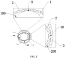
- the optical fiber 1 is located within the inner tube 2, and the outer wall surface of the optical fiber 1 is in partial contact with the inner wall surface of the inner tube 2 to form several first contact portions 9 extending in the axial direction. Axial gaps from these adjacent first contact portions 9 form first circulation channels 100.
- the cooling sleeve further includes an outer tube 3, the cross-sectional shape of which can be the same or different from the inner tube 2.
- the inner tube 2 is located within the outer tube 3, and the inner wall surface of the outer tube 3 is in partial contact with the outer wall surface of the inner tube 2 to form several second contact portions 10 extending in the axial direction. Axial gaps from these adjacent second contact portions 10 form second circulation channels 200. Proximal ends of the first circulation channels 100 and proximal ends of the second circulation channels 200 are connected with each other inside the proximal end of the outer tube 3 via a forming cavity 6; distal ends of the first circulation channels 100 and distal ends of the second circulation channels 200 are independently connected externally.
- first contact portions 9 and the second contact portions 10 are preferably arranged relative independently.
- the first contact portions can be in line contact or surface contact manner, and the second contact portions can also be in line contact or surface contact manner.
- the first contact portions can have a mixed form of line contact and surface contact
- the second contact portions can also have a mixed form of line contact and surface contact.
- the contact manners of the first contact portions and the second contact portions can both be the line contacts, or both be the surface contacts, or a mixed form of line contact and surface contact. Or, other combined contact manners that can realize the present disclosure could be considered. Regardless of the manner of contact, any equivalent transformations and modifications made within the scope of the present disclosure will be protected by it.
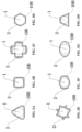
- FIGS. 3A-3H , and FIGS. 4A-4H are cross-sectional views of the section A-A and section B-B in FIG. 1 , respectively. These figures clearly show the contact manners, assembly relationship and cross-sectional shapes between the optical fiber 1 and the inner tube 2, and between the inner tube 2 and the outer tube 3. The specifics are described below.
- the first contact portions 9 may be formed when the outer wall surface of the optical fiber 1 contacts the inner wall surface of the inner tube 2 in a line contact manner, thereby forming several first line contact portions extending along the length direction of the inner tube 2 (e.g., there are 3 first line contact portions in FIG. 3A , and 7 first line contact portions in FIG. 3E ). Concurrently, several axial gaps from the adjacent first line contact portions collectively constitute first circulation channels 100, which allow fluid to flow through.
- the first contact portions 9 can also be formed when the outer wall surface of the optical fiber 1 contacts the inner wall surface of the inner tube 2 in a surface contact manner, thereby forming at least several first surface contact portions extending along the length direction of the inner tube 2 (e.g., there are 2 first surface contact portions in both FIG. 3F and FIG. 3G ). Similarly, several axial gaps from the adjacent first surface contact portions collectively constitute first circulation channels 100, which allow fluid to flow through.
- the second contact portions 10 may be formed when the inner wall surface of the outer tube 3 contacts the outer wall surface of the inner tube 2 in a surface contact manner, thereby forming several second surface contact portions extending along the length direction of the outer tube 3 (e.g., there are 3 second surface contact portions in FIG. 4A and 2 second surface contact portions in FIG. 4F ). Meanwhile, axial gaps from the adjacent second surface contact portions collectively constitute second circulation channels 200, which allow fluid to flow through.
- the second contact portions 10 can also be formed when the inner wall surface of the outer tube 3 contacts the outer wall surface of the inner tube 2 in a line contact manner, thereby forming several second line contact portions extending along the length direction of the outer tube 3 (e.g., there are 6 second line contact portions in FIG. 4D and 4 second line contact portions in FIG. 4H ).
- axial gaps from the adjacent second line contact portions collectively constitute second circulation channels 200, which allow fluid to flow through.
- the optical fiber 1, the inner tube 2 and the outer tube 3 are arranged coaxially.
- the several axial gaps are preferably distributed evenly along the circumferential direction.
- the first circulation channels 100 and the second circulation channels 200 are preferably arranged alternately.
- the temperature of the optical fiber located at the position of the first contact portions 9 is controlled and cooled by the cooling medium flowing through the second circulation channel 200
- the temperature of the optical fiber located at the position of the second contact portions 10 is controlled and cooled by the cooling medium flowing through the first circulation channels 100. That is, the cooling channels flowing through the inner tube (referred to in this disclosure as the first circulation channels) and the cooling channels flowing through the outer tube (referred to in this disclosure as the second circulation channels) should be staggered to ensure circumferential cooling.
- optical fiber, the inner tube, and the outer tube achieve coaxial self-arrangement-and-support, ensuring the optical fiber remains stable and firm during operation, but also ensures effective cooling of the optical fiber's periphery, ensuring the cooling capability of the cooling sleeve. Additionally, the configuration of the optical fiber, the inner tube, and the outer tube in this disclosure significantly reduces the size of the ablation device, benefiting minimally invasive surgical procedures.
- FIG. 3A to FIG. 3H and FIG. 4A to FIG. 4H are cross-sectional views of sections A-A and B-B in FIG. 1 , respectively.
- the present disclosure also presents or provides various types of inner and outer tubes.
- the cross-sectional shape of the inner tube 2 may be circular, quasi-circular or polygonal;
- the cross-sectional shape of the outer tube 3 may also be circular, quasi-circular or polygonal.
- the inner tube 2 and the outer tube 3 can also have the same cross-sectional shape, for example, as shown in FIG. 4D , both the inner tube 2 and the outer tube 3 have a hexagonal cross section.
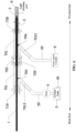
- FIG. 5 is a schematic structural diagram of the cooling sleeve in a preferred embodiment of the present disclosure.
- the optical fiber 1, the inner tube 2 and the outer tube 3 are arranged coaxially; and the proximal end of the optical fiber 1 is located within the proximal end of the inner tube 2, and the distal end of optical fiber 1 is far beyond the distal end of the inner tube 2, and the distal end of the inner tube 2 is located outside the distal end of the outer tube 3.
- the proximal end of the inner tube 2 connects with the proximal end of the outer tube 3 via a forming cavity 6.
- the distal end of the inner tube 2 is connected to an inlet pipeline 20, and the distal end of the outer tube 3 is connected to an outlet pipeline 30.
- the inner tube 2 is preferably a tubular structure with openings at both ends.
- the proximal end of the optical fiber 1 (generally provided with a light emitting part, as shown in FIG. 6 ) can either be located within the proximal end of the inner tube 2 or partially extend out of the proximal end of inner tube 2, with part of the proximal end of the optical fiber 1 retained within the forming cavity 6.
- the outer tube 3 is generally selected as a tube with one end open and the other end closed.
- the proximal end of the outer tube 3 is the closed end of the outer tube 3.
- the closed end is generally designed as a structure with a certain curvature or radius.
- the closed end of the outer tube 3 has a spherical structure, to facilitate the directional return of the cooling medium (such as saline), reducing the occurrence of turbulence.
- the inlet pipeline 20 is equipped with a pump 4 and cooling liquid, with the pump 4 preferably being a peristaltic pump, and the cooling liquid is stored in a coolant tank 5.
- a thermostatic heating device 40 is equipped either inside or outside the coolant tank 5. Alternatively, based on actual needs, the thermostatic heating device 40 can be arranged both inside and outside the coolant tank 5, to heat the cooling liquid to a temperature suitable for the human body, preventing irritation to tissues when the cooling fluid flows through them.
- the outlet pipeline 30 is attached with a device for recovering the cooling liquid, which can generally be set up as a waste liquid container 8.
- the present disclosure also provides an optical fiber catheter, which is convenient for operators to use during operation.
- FIG. 6 it is a schematic diagram of the structure of the optical fiber catheter.
- the optical fiber catheter mainly includes a cooling sleeve and a water-tight assembly 7 arranged on the outer periphery of the distal end of the cooling sleeve.
- the shape and other characteristics of the cooling sleeve have been described in detail above, and will not be repeated here.
- the specific structural features of the water-tight assembly 7 will be described in detail below with reference to the drawings and specific embodiments.
- the water-tight assembly 7 includes a pipe body 701 and a tubular connector 702.
- a first connection part is provided on a connection port 7011 of the pipe body 701.
- a branch tube 7013 connected externally is also provided on the pipe body 701.
- a second connection part is provided on the tubular connector 702.
- the second connection part matches the first connection part, and the tubular connector 702 is fixedly connected to the pipe body 701 through the second connection part and the first connection part.
- the connecting manner of the first connection part and the second connection part includes but is not limited to screw connection, flange connection, welding, clamp connection, ferrule connection, crimp connection, hot melt connection and clamp-fixed connection.
- the fixing manner between the first connection part and the second connection part can preferably adopt a threaded structure.
- This threaded connection makes it easier to control the gap between parts, and is also easy to disassemble and adjust. Furthermore, the threaded connection prevents the seal from twisting during assembly, ensures concentricity among a front pipe body and a rear pipe body and a tubular connector therebetween, and avoids uneven gaps and uneven force caused by twisting. The risk of leakage is further reduced, and the yield rate of products is improved.
- the water-tight assembly 7 includes a pipe body 701, and the parts used for connection at both ends of the pipe body 701 are the connection ports 7011. At least one protruding connection part 7012 (i.e., the first connection part described in the present disclosure) is provided on the peripheral wall of the connecting port 7011.
- the pipe body 701 also has a branch tube 7013 on one side that connects externally.
- the water-tight assembly 7 also includes a tubular connector 702.
- Notch connection slots 7021 i.e., the second connection part described in the present disclosure
- the notch connection slot 7021 is L-shaped, and the L-shaped notch connection slot 7021 includes an entrance part 70210 and a limiting part 70211.
- the tubular connector 702 can be firmly connected to the pipe body 701 through the notch connection slots 7021 and the protruding connection parts 7012.
- several reinforcing ribs 7020 may be added to the outer surface of the tubular connector 702, thereby greatly improving the impact resistance and durability of the tubular connector 702.
- the inner tube 2 has an open structure at both ends, while the outer tube 3 has one open end and one closed end.
- the optical fiber 1, the inner tube 2 and the outer tube 3 are arranged coaxially, the proximal end of the optical fiber 1 is partially located outside the proximal end of the inner tube 2, the distal end of the optical fiber 1 is far beyond the distal end of the inner tube 2, and the distal end of the inner tube 2 is located outside the distal end of the outer tube 3.
- the proximal end of the inner tube 2 and the proximal end of the outer tube 3 are connected with each other via the forming cavity 6.
- a water-tight assembly 7 is also provided.
- the water-tight assembly 7 includes at least two (2) pipe bodies 701 and one (1) tubular connector 702, and the outer diameter of the pipe body 701 fits the inner diameter of the tubular connector 702.
- the tubular connector 702 is clamped at a butt joint of the two pipe bodies 701, that is, the notch connection slots 7021 on the tubular connector 702 fits the protruding connection parts 7012 on the pipe bodies 701, facilitating the clamp connection of the tubular connector 702 and the pipe bodies 701.
- a seal is provided between the cooling sleeve and the water-tight assembly 7.
- the seal includes a bridging sealing plug 720 set at the butt joint of the two pipe bodies 701, a distal sealing plug 710 located inside a connection port 7011 at the distal end of the water-tight assembly 7, and a proximal sealing plug 730 located inside a connection port 7011 at the proximal end of the water-tight assembly 7.
- the butt joint of the two pipe bodies 701 is preferably arranged at a position close to the distal end of the inner tube 2; that is, the bridging sealing plug 720 is preferably set inside the two connection ports 7011 at the butt joint of the two pipe bodies 701.
- the inner diameter of a central hole of the bridging sealing plug 720 fits the outer diameter of the inner tube 2; the central hole of the distal sealing plug 710 fits the optical fiber 1, and the central hole of the proximal sealing plug 730 fits the outer tube 3.
- the outer wall of the optical fiber 1, the inner wall of the pipe body 701 (referring to the pipe body near the distal end of the cooling sleeve), the distal sealing plug 710 and the bridging sealing plug 720 can be sealed to form an inlet-type cavity that only connects to the inner tube 2.
- the inlet-type cavity is connected to the inlet pipeline 20, and the inlet pipeline 20 is equipped with a pump 4 and a coolant tank 5.
- a thermostatic heating device 40 is provided either inside or outside the coolant tank 5. The thermostatic heating device 40 can be used to heat the cooling medium to a temperature suitable for the human body, preventing irritation to tissues when the cooling fluid flows through them.
- the thermostatic heating device 40 ensures that the temperature of the cooling liquid in contact with human tissue is maintained at around 37.2°C, so as to avoid tissue reactions caused by a large temperature difference.
- the outer wall of the inner tube 2, the outer wall of the pipe body 701 (referring to the one closer to the proximal end of the cooling sleeve), the bridging sealing plug 720 and the proximal sealing plug 730 can be sealed to form an outlet-type cavity 704 that only connects to the outer tube 3.
- the outlet-type cavity 704 is connected to the outlet pipeline 30, and the outlet pipeline 30 is attached with a waste liquid container 8.
- the materials for the distal sealing plug 710, the bridging sealing plug 720 and the proximal sealing plug 730 are preferably soft silicone materials.
- the sealing effect is achieved through deformation and extrusion of the materials, ensuring a good sealing result.
- the materials for the inner tube and the outer tube can be made of glass with better light transmittance, enhancing the efficiency of the laser.
- resin materials can also be chosen, offering a wider range of choices and easier implementation.
Landscapes
- Health & Medical Sciences (AREA)
- Surgery (AREA)
- Physics & Mathematics (AREA)
- Life Sciences & Earth Sciences (AREA)
- Engineering & Computer Science (AREA)
- Medical Informatics (AREA)
- Nuclear Medicine, Radiotherapy & Molecular Imaging (AREA)
- Electromagnetism (AREA)
- Optics & Photonics (AREA)
- Biomedical Technology (AREA)
- Heart & Thoracic Surgery (AREA)
- Otolaryngology (AREA)
- Molecular Biology (AREA)
- Animal Behavior & Ethology (AREA)
- General Health & Medical Sciences (AREA)
- Public Health (AREA)
- Veterinary Medicine (AREA)
- Laser Surgery Devices (AREA)
- Radiation-Therapy Devices (AREA)
Applications Claiming Priority (2)
| Application Number | Priority Date | Filing Date | Title |
|---|---|---|---|
| CN202110484230.XA CN113081255A (zh) | 2021-04-30 | 2021-04-30 | 一种冷却套管及具有该冷却套管的光纤导管 |
| PCT/CN2022/089280 WO2022228428A1 (zh) | 2021-04-30 | 2022-04-26 | 一种冷却套管及具有该冷却套管的光纤导管 |
Publications (3)
| Publication Number | Publication Date |
|---|---|
| EP4331518A1 true EP4331518A1 (de) | 2024-03-06 |
| EP4331518A4 EP4331518A4 (de) | 2025-04-16 |
| EP4331518B1 EP4331518B1 (de) | 2026-04-08 |
Family
ID=76681147
Family Applications (1)
| Application Number | Title | Priority Date | Filing Date |
|---|---|---|---|
| EP22794898.1A Active EP4331518B1 (de) | 2021-04-30 | 2022-04-26 | Kühlhülse und glasfaserkatheter damit |
Country Status (7)
| Country | Link |
|---|---|
| US (1) | US20240197398A1 (de) |
| EP (1) | EP4331518B1 (de) |
| KR (1) | KR20230164180A (de) |
| CN (1) | CN113081255A (de) |
| BR (1) | BR112023022590A2 (de) |
| MX (1) | MX2023012067A (de) |
| WO (1) | WO2022228428A1 (de) |
Cited By (1)
| Publication number | Priority date | Publication date | Assignee | Title |
|---|---|---|---|---|
| EP4663145A1 (de) * | 2024-06-12 | 2025-12-17 | Hangzhou GenLight MedTech Co., Ltd. | Ablationskatheter und ablationssystem |
Families Citing this family (4)
| Publication number | Priority date | Publication date | Assignee | Title |
|---|---|---|---|---|
| CN113081255A (zh) * | 2021-04-30 | 2021-07-09 | 杭州佳量医疗科技有限公司 | 一种冷却套管及具有该冷却套管的光纤导管 |
| CN114176770B (zh) * | 2021-12-31 | 2023-01-24 | 华科精准(北京)医疗科技有限公司 | 一种冷却套管和冷却装置 |
| CN116407271A (zh) * | 2021-12-31 | 2023-07-11 | 华科精准(北京)医疗科技有限公司 | 一种激光消融组件和激光消融系统 |
| CN115300099A (zh) * | 2022-08-17 | 2022-11-08 | 北京化工大学 | 激光消融冷却器及其制造方法 |
Family Cites Families (14)
| Publication number | Priority date | Publication date | Assignee | Title |
|---|---|---|---|---|
| US5827267A (en) * | 1992-02-18 | 1998-10-27 | Angeion Corporation | Cooled multi-fiber medical connector |
| US6802838B2 (en) * | 2002-04-22 | 2004-10-12 | Trimedyne, Inc. | Devices and methods for directed, interstitial ablation of tissue |
| US7270656B2 (en) * | 2003-11-07 | 2007-09-18 | Visualase, Inc. | Cooled laser fiber for improved thermal therapy |
| US7127033B2 (en) * | 2004-02-28 | 2006-10-24 | Xoft, Inc. | Miniature x-ray tube cooling system |
| US10363092B2 (en) * | 2006-03-24 | 2019-07-30 | Neuwave Medical, Inc. | Transmission line with heat transfer ability |
| GB2457299B (en) * | 2008-02-09 | 2013-04-24 | Uk Investments Associates Llc | Microwave applicator |
| WO2014054117A1 (ja) * | 2012-10-02 | 2014-04-10 | 三菱電機株式会社 | 二重管式熱交換器および冷凍サイクル装置 |
| EP3209377B1 (de) * | 2014-10-22 | 2019-03-06 | Cardiac Pacemakers, Inc. | Freisetzungsvorrichtungen und verfahren für elektrodenlose herzvorrichtungen |
| US20170319267A1 (en) * | 2016-05-05 | 2017-11-09 | Covidien Lp | Ablation instruments with a member having a triangular cross-section |
| CN109009429A (zh) * | 2018-06-19 | 2018-12-18 | 华科精准(北京)医疗科技有限公司 | 用于激光消融的装置 |
| CN111120755A (zh) * | 2020-01-21 | 2020-05-08 | 成都奥森泰科技有限公司 | 一种管件快接结构 |
| CN113081255A (zh) * | 2021-04-30 | 2021-07-09 | 杭州佳量医疗科技有限公司 | 一种冷却套管及具有该冷却套管的光纤导管 |
| CN215425064U (zh) * | 2021-04-30 | 2022-01-07 | 杭州佳量医疗科技有限公司 | 一种冷却套管及具有该冷却套管的光纤导管 |
| CN113180823A (zh) * | 2021-04-30 | 2021-07-30 | 杭州佳量医疗科技有限公司 | 一种可清除流体气泡的光纤导管冷却系统 |
-
2021
- 2021-04-30 CN CN202110484230.XA patent/CN113081255A/zh active Pending
-
2022
- 2022-04-26 MX MX2023012067A patent/MX2023012067A/es unknown
- 2022-04-26 US US18/287,076 patent/US20240197398A1/en active Pending
- 2022-04-26 BR BR112023022590A patent/BR112023022590A2/pt unknown
- 2022-04-26 EP EP22794898.1A patent/EP4331518B1/de active Active
- 2022-04-26 WO PCT/CN2022/089280 patent/WO2022228428A1/zh not_active Ceased
- 2022-04-26 KR KR1020237038070A patent/KR20230164180A/ko active Pending
Cited By (1)
| Publication number | Priority date | Publication date | Assignee | Title |
|---|---|---|---|---|
| EP4663145A1 (de) * | 2024-06-12 | 2025-12-17 | Hangzhou GenLight MedTech Co., Ltd. | Ablationskatheter und ablationssystem |
Also Published As
| Publication number | Publication date |
|---|---|
| EP4331518B1 (de) | 2026-04-08 |
| KR20230164180A (ko) | 2023-12-01 |
| US20240197398A1 (en) | 2024-06-20 |
| EP4331518A4 (de) | 2025-04-16 |
| CN113081255A (zh) | 2021-07-09 |
| BR112023022590A2 (pt) | 2024-01-09 |
| WO2022228428A1 (zh) | 2022-11-03 |
| MX2023012067A (es) | 2023-10-23 |
Similar Documents
| Publication | Publication Date | Title |
|---|---|---|
| EP4331518A1 (de) | Kühlhülse und glasfaserkatheter damit | |
| EP2497436B1 (de) | Kryostat für kryochirurgisches System | |
| US7207985B2 (en) | Detachable cryosurgical probe | |
| EP2012721B1 (de) | Wärmetaucher-katheter mit mehrlumen-rohr mit einem flüssigkeitsrücklauf-gang | |
| AU694776B2 (en) | Apparatus and method for interstitial laser treatment | |
| CN115836909B (zh) | 射频消融电极及其应用以及射频消融系统 | |
| WO2012139085A4 (en) | System and method for cooling of a heated surgical instrument and/or surgical site and treating tissue | |
| WO2023078168A1 (zh) | 一种医用光纤导向结构及导向方法 | |
| WO2023087671A1 (zh) | 冷热消融针系统 | |
| CN215425064U (zh) | 一种冷却套管及具有该冷却套管的光纤导管 | |
| CN216455275U (zh) | 一种用于手术消融器件的导向结构 | |
| CN114176770B (zh) | 一种冷却套管和冷却装置 | |
| CN117958959A (zh) | 一种用于神经组织消融的水冷射频电极结构 | |
| CN222804344U (zh) | 用于消融导管的连接结构、消融导管及消融系统 | |
| CN118576310A (zh) | 消融导管及消融系统 | |
| CN115568936A (zh) | 深部电极 | |
| CN212234673U (zh) | 一种具有冷却毛细腔的微波消融针 | |
| CN119791791B (zh) | 柔性穿刺结构和蒸汽消融系统 | |
| CN223886959U (zh) | 一种抽吸结构消融针 | |
| US20260076727A1 (en) | Split-type ablation needle and cryoablation puncture system | |
| CN219878263U (zh) | 一种柔性射频消融导管及射频消融器械 | |
| CN115300099A (zh) | 激光消融冷却器及其制造方法 | |
| CN117618106A (zh) | 激光消融组件和激光消融系统 | |
| WO2024221002A1 (en) | A surgical probe device, and systems and methods for cooling the same | |
| CN117958947A (zh) | 一种稳固连接装置及黏膜手术器械 |
Legal Events
| Date | Code | Title | Description |
|---|---|---|---|
| STAA | Information on the status of an ep patent application or granted ep patent |
Free format text: STATUS: THE INTERNATIONAL PUBLICATION HAS BEEN MADE |
|
| PUAI | Public reference made under article 153(3) epc to a published international application that has entered the european phase |
Free format text: ORIGINAL CODE: 0009012 |
|
| STAA | Information on the status of an ep patent application or granted ep patent |
Free format text: STATUS: REQUEST FOR EXAMINATION WAS MADE |
|
| 17P | Request for examination filed |
Effective date: 20231003 |
|
| AK | Designated contracting states |
Kind code of ref document: A1 Designated state(s): AL AT BE BG CH CY CZ DE DK EE ES FI FR GB GR HR HU IE IS IT LI LT LU LV MC MK MT NL NO PL PT RO RS SE SI SK SM TR |
|
| DAV | Request for validation of the european patent (deleted) | ||
| DAX | Request for extension of the european patent (deleted) | ||
| A4 | Supplementary search report drawn up and despatched |
Effective date: 20250317 |
|
| RIC1 | Information provided on ipc code assigned before grant |
Ipc: A61B 18/24 20060101AFI20250311BHEP |
|
| STAA | Information on the status of an ep patent application or granted ep patent |
Free format text: STATUS: EXAMINATION IS IN PROGRESS |
|
| 17Q | First examination report despatched |
Effective date: 20250828 |
|
| GRAP | Despatch of communication of intention to grant a patent |
Free format text: ORIGINAL CODE: EPIDOSNIGR1 |
|
| STAA | Information on the status of an ep patent application or granted ep patent |
Free format text: STATUS: GRANT OF PATENT IS INTENDED |
|
| INTG | Intention to grant announced |
Effective date: 20251117 |
|
| GRAS | Grant fee paid |
Free format text: ORIGINAL CODE: EPIDOSNIGR3 |
|
| GRAA | (expected) grant |
Free format text: ORIGINAL CODE: 0009210 |
|
| STAA | Information on the status of an ep patent application or granted ep patent |
Free format text: STATUS: THE PATENT HAS BEEN GRANTED |
|
| AK | Designated contracting states |
Kind code of ref document: B1 Designated state(s): AL AT BE BG CH CY CZ DE DK EE ES FI FR GB GR HR HU IE IS IT LI LT LU LV MC MK MT NL NO PL PT RO RS SE SI SK SM TR |
|
| REG | Reference to a national code |
Ref country code: CH Ref legal event code: F10 Free format text: ST27 STATUS EVENT CODE: U-0-0-F10-F00 (AS PROVIDED BY THE NATIONAL OFFICE) Effective date: 20260408 Ref country code: GB Ref legal event code: FG4D |
|
| REG | Reference to a national code |
Ref country code: DE Ref legal event code: R096 Ref document number: 602022034188 Country of ref document: DE |