EP4330493B1 - Mastarm-segment für eine betonpumpe - Google Patents
Mastarm-segment für eine betonpumpe Download PDFInfo
- Publication number
- EP4330493B1 EP4330493B1 EP22724102.3A EP22724102A EP4330493B1 EP 4330493 B1 EP4330493 B1 EP 4330493B1 EP 22724102 A EP22724102 A EP 22724102A EP 4330493 B1 EP4330493 B1 EP 4330493B1
- Authority
- EP
- European Patent Office
- Prior art keywords
- arm segment
- lower belt
- connection
- transition piece
- boom arm
- Prior art date
- Legal status (The legal status is an assumption and is not a legal conclusion. Google has not performed a legal analysis and makes no representation as to the accuracy of the status listed.)
- Active
Links
Images




Classifications
-
- B—PERFORMING OPERATIONS; TRANSPORTING
- B66—HOISTING; LIFTING; HAULING
- B66C—CRANES; LOAD-ENGAGING ELEMENTS OR DEVICES FOR CRANES, CAPSTANS, WINCHES, OR TACKLES
- B66C23/00—Cranes comprising essentially a beam, boom, or triangular structure acting as a cantilever and mounted for translatory of swinging movements in vertical or horizontal planes or a combination of such movements, e.g. jib-cranes, derricks, tower cranes
- B66C23/62—Constructional features or details
- B66C23/64—Jibs
- B66C23/68—Jibs foldable or otherwise adjustable in configuration
-
- B—PERFORMING OPERATIONS; TRANSPORTING
- B66—HOISTING; LIFTING; HAULING
- B66C—CRANES; LOAD-ENGAGING ELEMENTS OR DEVICES FOR CRANES, CAPSTANS, WINCHES, OR TACKLES
- B66C23/00—Cranes comprising essentially a beam, boom, or triangular structure acting as a cantilever and mounted for translatory of swinging movements in vertical or horizontal planes or a combination of such movements, e.g. jib-cranes, derricks, tower cranes
- B66C23/62—Constructional features or details
- B66C23/64—Jibs
- B66C23/70—Jibs constructed of sections adapted to be assembled to form jibs or various lengths
-
- E—FIXED CONSTRUCTIONS
- E04—BUILDING
- E04G—SCAFFOLDING; FORMS; SHUTTERING; BUILDING IMPLEMENTS OR AIDS, OR THEIR USE; HANDLING BUILDING MATERIALS ON THE SITE; REPAIRING, BREAKING-UP OR OTHER WORK ON EXISTING BUILDINGS
- E04G21/00—Preparing, conveying, or working-up building materials or building elements in situ; Other devices or measures for constructional work
- E04G21/02—Conveying or working-up concrete or similar masses able to be heaped or cast
- E04G21/04—Devices for both conveying and distributing
- E04G21/0418—Devices for both conveying and distributing with distribution hose
- E04G21/0436—Devices for both conveying and distributing with distribution hose on a mobile support, e.g. truck
-
- E—FIXED CONSTRUCTIONS
- E04—BUILDING
- E04G—SCAFFOLDING; FORMS; SHUTTERING; BUILDING IMPLEMENTS OR AIDS, OR THEIR USE; HANDLING BUILDING MATERIALS ON THE SITE; REPAIRING, BREAKING-UP OR OTHER WORK ON EXISTING BUILDINGS
- E04G21/00—Preparing, conveying, or working-up building materials or building elements in situ; Other devices or measures for constructional work
- E04G21/02—Conveying or working-up concrete or similar masses able to be heaped or cast
- E04G21/04—Devices for both conveying and distributing
- E04G21/0418—Devices for both conveying and distributing with distribution hose
- E04G21/0445—Devices for both conveying and distributing with distribution hose with booms
-
- Y—GENERAL TAGGING OF NEW TECHNOLOGICAL DEVELOPMENTS; GENERAL TAGGING OF CROSS-SECTIONAL TECHNOLOGIES SPANNING OVER SEVERAL SECTIONS OF THE IPC; TECHNICAL SUBJECTS COVERED BY FORMER USPC CROSS-REFERENCE ART COLLECTIONS [XRACs] AND DIGESTS
- Y10—TECHNICAL SUBJECTS COVERED BY FORMER USPC
- Y10T—TECHNICAL SUBJECTS COVERED BY FORMER US CLASSIFICATION
- Y10T137/00—Fluid handling
- Y10T137/8593—Systems
- Y10T137/8807—Articulated or swinging flow conduit
Definitions
- the invention relates to a boom arm segment for a concrete pump.
- a concrete pump boom arm With a concrete pump boom arm, a delivery line of a concrete pump can be guided in such a way that the liquid concrete delivered by the concrete pump is applied in an area remote from the concrete pump.
- a concrete pump boom arm is usually made up of a plurality of boom arm segments, whereby in an unfolded state the boom arm segments together make up the length of the boom arm and whereby in a folded state the boom arm segments are folded together into a compact state in order to facilitate transport.
- Mast arm segments are, for example, from the publications CN 205 036 090 U and CN 110 984 578 B known.
- Concrete pumps normally deliver liquid concrete in bursts, meaning that the boom arms are subjected to considerable dynamic loads.
- the boom arm segments can be folded differently when the concrete pump is in operation, depending on the distance from the concrete pump at which the liquid concrete is to be delivered. This means that the tensile and compressive loads on a boom arm segment act in very different directions depending on the operating state of the boom arm. For these reasons, the boom arm segments of a concrete pump are subjected to special loads during operation.
- the invention is based on the object of presenting a concrete pump boom segment that is lightweight and inexpensive to manufacture. Based on the above-mentioned prior art, the object is achieved with the features of the independent claims. Advantageous embodiments are specified in the subclaims.
- the mast arm segment comprises an upper chord, a lower chord and two side parts connecting the upper chord and the lower chord.
- the mast arm segment comprises an articulated connection which defines a pivot axis for a pivot connection between the mast arm segment and an adjacent structure.
- the pivot axis is arranged below the plane of the lower chord.
- a transition piece extends between the lower chord and the articulated connection.
- a first connection is formed between the transition piece and the lower chord. The first connection is spaced from the end of the lower chord. This information refers to the end of the lower chord adjacent to the transition piece, i.e. closest to it; the transition piece is also spaced from the opposite end of the lower chord.
- the transition piece is enclosed between a first reinforcing part and a second reinforcing part, which are laterally adjacent to the transition piece.
- the reinforcing parts each have a lower edge which extends from the articulated connection to the lower chord.
- the lower edges form an angle with the plane of the lower flange that is smaller than the angle formed by the transition piece with the plane of the lower flange.
- the invention has recognized that the transition piece between the lower chord and the joint connection creates a particularly favorable possibility of introducing the forces acting in the area of the joint connection into the mast arm segment.
- the transition is arranged at a distance from the end of the lower chord.
- the lower chord can extend from an end adjacent to the articulation connection along a straight line towards an opposite end of the boom arm segment (longitudinal direction).
- the end of the boom arm segment adjacent to the articulation connection can be the proximal end.
- the plane of the lower chord is defined by the longitudinal direction of the lower chord and the dimension parallel to the pivot axis of the articulation connection. If the lower chord does not extend over the entire length of the boom arm in one plane, the plane of the lower chord is defined by a section of the lower chord adjacent to the articulation connection.
- the lower flange can also extend transversely in the plane of the lower flange.
- Preferred embodiments are those in which the lower flange has a shape extending out of the plane of the lower flange in the transverse direction.
- the lower flange can have one or more bends or be provided with one or more bevels.
- the direction of the edges/bends can be parallel to the longitudinal direction of the mast arm segment, so that a shape extending out of the plane is produced in the transverse direction.
- the lower flange can have a curved shape in the transverse direction, for example by bending the lower flange so that the sum of the bevels corresponds to a curvature.
- the curvature can be aligned so that the distance between the pivot axis of the joint connection and a central area of the lower flange is smaller than the Distance between the pivot axis and a peripheral area of the bottom flange.
- the plane of the bottom flange is defined by the area of the bottom flange that is the closest to the hinge connection.
- edges that are bent in opposite directions are also possible, so that one or more corrugations are formed in the bottom flange.
- the lower chord is not flat in the transverse direction, it is advantageous if it is straight in the longitudinal direction, i.e. does not extend out of the plane of the lower chord in the longitudinal direction. If there is no overlap between the plane of the lower chord and the articulated connection, a direct connection between the lower chord and the articulated connection arranged below the plane of the lower chord is not possible.
- the invention proposes creating this connection using a transition piece. Although this means that an additional component has to be processed and additional work steps are required when producing the mast arm segment - compared to designs in which the articulated connection can be connected directly to the lower chord - the solution has proven to be advantageous overall.
- the boom arm segment is designed to be pivotally connected to an adjacent structure via a pivot joint.
- the adjacent structure can be another segment of the boom arm or a base frame of the concrete pump.
- the pivot joint is formed by a first pivot connection, which is an element of the boom arm segment, and by a second pivot connection, which is an element of the adjacent structure separate from the boom arm segment.
- the position of the pivot axis is defined by the pivot connection of the boom arm segment.
- the joint connection can comprise a joint bore, wherein the axis of the joint bore corresponds to the pivot axis.
- the joint connection can comprise a structure within which the joint bore is formed.
- the joint connection can be a piece of pipe within which the joint bore extends.
- the joint connection can form a receptacle for a joint bolt.
- the transition piece extends from the first connection, via which the transition piece is connected to the lower chord, diagonally downwards in the direction of the hinge connection. In this way, the transition piece forms an angle with the plane of the lower chord.
- the transition piece can form an angle between 5° and 50°, preferably between 10° and 40°, with the plane of the lower chord. Angles outside this range are less favorable for the transmission of forces between the lower chord and the hinge connection.
- the transition piece can extend along a straight line between the bottom flange and the hinge connection. Transversely, the transition piece can also be straight, so that the transition piece has a flat shape overall. Alternatively, the bottom flange can have one or more bends or be provided with one or more bevels. The direction of the edges/bends can be parallel to the longitudinal direction, so that a shape that extends out of the plane is obtained in the transverse direction.
- the transition piece can have a curved shape in the transverse direction, for example by beveling the bottom flange so that the sum of the bevels corresponds to a curvature. In the lateral dimension, the transition piece can extend over the entire width of the bottom flange that the bottom flange has in this section.
- a second connection can be formed between the transition piece and the joint connection.
- the distance between the second connection and the plane of the lower chord can be greater than the distance between the pivot axis and the plane of the lower chord.
- the transition piece can also be arranged such that there is no direct connection between the transition piece and the articulated connection.
- the transition piece can in this case comprise a section that is arranged below the articulated connection. Adequate force transmission between the transition piece and the articulated connection can be ensured, for example, by arranging both the transition piece and the articulated connection between two reinforcing parts, so that the force transmission between the articulated connection and the transition piece takes place through the reinforcing parts.
- the transition piece connects to an end plate that forms a connection to the upper chord at the end of the mast arm segment.
- the transition piece can be made of sheet steel.
- the transition piece can be welded to the bottom flange and/or to the hinge connection.
- the transition piece can be designed so that it is flush with the hinge connection and/or the bottom flange over its entire width.
- the welded connection to the hinge connection and/or the welded connection to the bottom flange can extend over the entire width of the transition piece.
- the distance between the pivot axis of the hinge connection and the plane of the lower flange can be so large that the plane of the lower flange does not intersect the hinge hole of the hinge connection.
- the distance between the pivot axis of the hinge connection and the plane of the lower flange can be so large that the plane of the lower flange does not intersect the structure of the hinge connection.
- the mast arm segment comprises a reinforcement part that extends from the joint connection to the lower flange.
- the reinforcement part can extend over the lower flange into a side part of the mast arm segment.
- the reinforcement part can be designed to transfer forces acting on the joint connection into the mast arm segment.
- the reinforcement part comprises a lower edge that extends from the joint connection to the lower flange.
- the lower edge encloses an angle with the plane of the lower flange that is smaller than the angle that the transition piece encloses with the plane of the lower flange.
- the difference in the angles can be, for example, between 2° and 20°, preferably between 5° and 10°.
- the distance between the lower edge of the reinforcement member and the plane of the bottom flange may be greater than the distance between the transition piece and the plane of the bottom flange. This may apply in particular to the area where the transition piece is connected to the hinge connection. This may also apply over the entire length of the transition piece.
- the transition piece may be welded to the reinforcement member along its length. A design in which the transition piece is spaced from the lower edge of the reinforcement member has the advantage that the forces from the hinge connection can be distributed more evenly.
- the transition piece is enclosed between a first reinforcement part and a second reinforcement part, which are laterally adjacent to the transition piece.
- the reinforcement parts can also enclose the hinge connection and/or a section of the bottom flange between them. Both reinforcement parts can have the aforementioned features.
- the end of the bottom flange may be enclosed between the reinforcement members.
- the end of the bottom flange may be spaced from an edge of the reinforcement member which is an extension of the bottom flange.
- the connection between the transition piece and the lower chord is at a distance from the end of the lower chord, so there is a section of the transition piece that is arranged below the lower chord.
- the section of the transition piece arranged below the lower chord can make up at least 5%, preferably at least 10%, more preferably at least 30% of the length of the transition piece.
- This information refers to the area of the lower chord in which the proximal end of the lower chord is at the greatest distance from the transition with the transition piece. This can be a lateral area of the lower chord with which the lower chord runs into the reinforcement parts.
- a middle area of the lower chord can be cut out and set back.
- the set-back area is also at a distance from the connection between the transition piece and the lower chord.
- transition piece is particularly useful when the side parts of the mast arm segment are bent inwards. It is then possible to connect the two reinforcement parts, which enclose the transition piece between them, to the side parts as described below.
- the side part of the mast arm segment can have a bevel so that a central portion of the side part is laterally offset inwards relative to an edge portion of the side part. Between the edge portion and the central portion there can be a transition portion which forms a connection between the edge portion and the central portion
- the reinforcing part can have a material thickness that bridges the lateral offset between the edge section and the central section.
- the reinforcement part can be butt-jointed to the transition section. In the areas of the edge section and the central section adjacent to the transition section, a direct connection can also be created between the reinforcement part and the side part.
- the connection between the side part and the reinforcement part can be designed as a welded connection.
- the welded connection can be butt-jointed over the entire length of the connection between the reinforcement part and the side part, so that an end face of the reinforcement part is welded to an end face of the side part. It is also possible for the welded connection to comprise butt-jointed and overlapping welded sections.
- the butt-jointed sections of the welded connection can comprise the connection to the transition section of the side part and other sections.
- the reinforcement member is butt-jointed to the edge portion of the side member and overlapped to the central portion of the side member.
- the edge portion of the side member may adjoin the upper chord or the lower chord of the mast arm segment.
- the reinforcement member may be joined to the central portion of the side member by a weld extending along a portion of a peripheral edge of the reinforcement member.
- the side part may be designed to include an upper edge portion adjacent to the upper flange and a lower edge portion adjacent to the lower flange.
- the reinforcing part may be dimensioned to be in contact with both the transition portion between the central portion and the upper edge portion as well as the transition portion between the central portion and the lower edge portion.
- the reinforcing member may be butt-connected to both the upper edge portion and the lower edge portion.
- the reinforcing member may be in an overlapping connection with the central portion. An upper end of the reinforcing member may end in the upper edge portion.
- the reinforcement part can comprise an end region which runs out inside the side part.
- the end region can run out in the form of a taper in the side part.
- the end region can overlap with the side part.
- the tip of the end region can run out in the central section of the side part.
- the tip is the outermost point of the end region, regardless of whether the end region tapers to a point there or has a different shape, for example is rounded.
- the tip of the end region can be arranged close to the neutral fiber of the mast arm segment, which means that the distance between the tip of the end region and the nearest belt is at least a factor of 2, preferably a factor of 3, more preferably a factor of 5 greater than the distance between the tip and the neutral fiber.
- the joint connection can form a proximal joint receptacle of the boom arm segment.
- a receptacle for a joint bolt can be formed in the reinforcement part.
- An articulated lever can be connected to the reinforcement part, to which a hydraulic cylinder can be connected.
- the hydraulic cylinder has the function of pivoting the boom arm segment relative to an adjacent structure, in particular relative to an adjacent boom arm segment.
- the articulated lever can be connected to the reinforcement part via a pivot connection.
- the mast arm segment can comprise a fastening receptacle for a conveyor line holder.
- the fastening receptacle can extend transversely through the mast arm segment and form a transverse connection between the opposite side parts of the mast arm segment.
- the fastening receptacle can be welded to each of the side parts.
- the fastening receptacle can extend between the central sections of the opposite side parts. In this way, the fastening receptacle can provide additional protection against the side parts of the mast arm segment deviating to the side under load.
- the connection to the side parts allows the forces exerted by the fastened elements to be easily transmitted to the side parts.
- the fastening receptacle can protrude from the side part.
- the fastening receptacle can be designed so that a holder for the conveyor line can be connected.
- blind holes can be provided for a screw connection.
- the holder it is also possible for the holder to be welded to the fastening receptacle, for example.
- the mast arm segment comprises a holder for a conveyor line connected to the fastening receptacle and/or a conveyor line connected to the fastening receptacle.
- hydraulic lines can be connected to the mast arm segment, via which, for example, hydraulic devices for folding in and out the mast arm can be operated.
- the mast arm segment can comprise a plurality of such fastening receptacles, in particular at least two fastening receptacles, preferably at least three fastening receptacles, more preferably at least four fastening receptacles.
- the fastening receptacles can be substantially evenly distributed over the length of the mast arm segment.
- One or more of the mounting brackets can be connected to a reinforcement part.
- the conveyor line can extend over the length of the boom arm segment.
- the conveyor line can comprise a joint part at one or both of its ends, which is designed to form a pivotable connection to a conveyor line of an adjacent boom arm segment.
- the pivot axis defined by the joint part can be coaxial to the pivot axis of the joint connection and thus coaxial to the axis of the boom arm pivot joint.
- the conveyor line can be arranged to the side of the boom arm segment.
- the invention also relates to a concrete pump boom arm with a plurality of boom arm segments, wherein at least one of the boom arm segments is designed according to the invention.
- a swivel joint is formed between every two adjacent boom arm segments.
- the axis of the swivel joint can be aligned such that it extends through both side parts of the boom arm segment, wherein the two side parts are preferably cut at right angles or enclose an angle of less than 10°, preferably less than 5°, with this direction.
- the belt surfaces can extend parallel to the swivel axis.
- the joint can comprise a first articulated lever which is pivotally attached to a first boom arm segment.
- the joint can comprise a second articulated lever which is pivotally attached to the second boom arm segment and which is also pivotally attached to the first articulated lever.
- a hydraulic cylinder can extend from the first boom arm segment to the first articulated lever so that a lifting movement of the hydraulic cylinder is translated into a pivoting movement between the boom arm segments.
- the hydraulic cylinder is preferably attached to the first articulated lever beyond the second articulated lever as viewed from the first boom arm segment.
- the concrete pump boom arm can comprise a delivery line for a thick material, in particular fresh concrete, which extends along the boom arm.
- Each segment of the boom arm can be assigned a segment of the delivery line. Adjacent segments of the delivery line can be connected to one another via a joint, wherein the joint axis is preferably coaxial with the joint with which the associated boom arm segments are connected to one another.
- the individual segment of the delivery line can be designed as a rigid pipeline.
- FIG. 1 The truck 14 shown is equipped with a concrete pump 15 which conveys liquid concrete from a pre-filling container 16 through a delivery line 17.
- the delivery line 17 extends along a boom arm 18 which is rotatably mounted on a slewing ring 19.
- the boom arm 18 comprises three boom arm segments 20, 21, 22 which are connected to one another in an articulated manner. By pivoting the boom arm segments 20, 21, 22 relative to one another via the joints, the boom arm 18 can be switched between a folded state ( Fig. 1 ) and an unfolded state ( Fig. 2 ).
- the delivery line 17 extends beyond the distal end of the third boom arm segment 22 so that the liquid concrete can be applied in an area remote from the concrete pump 15.
- the loads act on boom arm segments 20, 21, 22 in very different directions.
- the boom arm is exposed to high dynamic loads due to the intermittent delivery of the liquid concrete.
- the swivel joints between the mast arm segments 20, 21, 22 are designed to allow a large swivel angle.
- the mast arm segments 20, 21, 22 are essentially parallel to each other and form a small angle between them.
- the mast arm segments 20, 21, 22 extend approximately in extension to each other.
- the joint construction is in Fig. 4 using the example of the swivel joint between the first mast arm segment 20 and the second mast arm segment 21.
- the swivel axis 74 is formed by a hinge pin 23, through which a proximal end of the mast arm segment 21 is connected to a distal end of the mast arm segment 20. Adjacent to the hinge pin 23, a first articulated lever is attached to the first mast arm segment 20. 24. A second articulated lever 25 is attached to the second boom arm segment 21, adjacent to the articulated pin 23.
- the two articulated levers are articulated to one another at 26.
- a hydraulic cylinder 27 extends from a receptacle 28 on the first boom arm segment 20 to the outer end of the first articulated lever 24. A lifting movement of the hydraulic cylinder 27 is translated into a pivoting movement between the boom arm segments 20, 21 via the articulated levers 24, 25.
- the mast arm segment 30 extends from a proximal end 31 to a distal end 32.
- the mast arm segment 30 is designed as a box-shaped profile with an upper flange 33, a lower flange 34 and two side parts 35, 36.
- the box-shaped profile of the mast arm segment tapers continuously from the proximal end 31 to the receptacle 28 for the hydraulic cylinder.
- the two side parts 35, 36 as well as the upper flange 33 and the lower flange 34 thus approach each other with increasing distance from the proximal end 31.
- the mast arm segment 30 is reinforced with a first reinforcement part 40, which forms a proximal joint receptacle 57 of the mast arm segment 30.
- the box-shaped profile extends in the direction of the distal end 32.
- the box-shaped profile is composed of an upper half-shell 41 and a lower half-shell 47, each of which is designed as folded metal sheets.
- the two side parts 35, 36 each comprise an upper edge section 42, which adjoins the upper flange 33, and a lower edge section 43, which adjoins the lower flange 34.
- the upper edge sections 42 and the lower edge sections 43 lie in the same plane.
- a central section 44 is arranged between the edge sections 42, 43, which has a lateral offset 56 relative to the edge sections 42, 43.
- the side parts 35, 36 are bent inwards so that the central sections 44 of the two side parts 35, 36 are closer to one another than the edge sections 42, 43 of the side parts 35, 36.
- transition sections 45, 46 are formed, each of which encloses an angle of approximately 30° with the plane of the edge sections 42, 43 or the plane of the central sections 44 parallel thereto.
- the upper half-shell 41 comprises the upper flange, the upper edge sections 42, the upper transition sections 45 and the upper part of the central sections 44 of both side parts 35, 36.
- the lower half-shell 47 comprises the lower flange 34, the lower edge sections 43, the lower transition sections 46 and the lower part of the central sections 44 of both side parts 35, 36.
- the upper end of the lower half-shell 47 overlaps with the lower end of the upper half-shell 41.
- a weld seam is formed at the lower end of the upper half-shell 47, by which the two half-shells 41, 47 are connected to one another.
- the lower half-shell 47 is folded inwards with its end edge 55 and thus forms a buckling stiffener for the box profile.
- the first reinforcement part 40 has a greater material thickness than the box profile made of the half shells 41, 47, see Fig. 12
- the outside of the first reinforcement part 40 coincides with the outside of the upper edge sections 42.
- the inside of the first reinforcement part 40 coincides with the outside of the central sections 44. With the transition sections 45, 46, the box profile alternates between the outside and the inside of the first reinforcement part 40.
- the transition sections 45, 46 and the edge sections 42, 43 are welded butt-jointly to the first reinforcing part 40.
- the central sections 44 overlap with the first reinforcing part 40.
- the connection between the first reinforcing part 40 and the central sections 44 is formed by a circumferential weld seam around the first reinforcing part 40.
- a joint bore 37 is formed in the first reinforcement part 40.
- the joint bore accommodates the joint bolt 23, which connects the mast arm segment 30 to an adjacent mast arm segment.
- the joint lever 25 can be connected next to the joint bore 37.
- the mast arm segment 30 comprises a further joint bore 37 near its distal end as well as a further stud bolt 38, to which a joint lever 24 can be connected.
- the mast arm segment 30 comprises a further reinforcement part 50, which forms the holder 28 for the hydraulic cylinder.
- the further reinforcement part 50 has the same material thickness as the first reinforcement part 40 and fits into the contour of the upper half-shell 41 in the same way.
- the further reinforcement part 50 therefore overlaps with the central sections 44 of the side parts 35, 36 and is connected there by a circumferential weld seam to the upper half-shell 41.
- the upper transition section 45 and the upper edge section 42 are welded butt-jointly to the further reinforcement part 50.
- the distal joint receptacle 51 shown comprises a reinforcing plate 52 which is doubled onto the plate of the box profile.
- the connection between the reinforcing plate 52 and the box profile is formed by a circumferential weld seam which extends over the circumference of the reinforcing plate 52.
- the joint receptacle 51 comprises a joint bore 37 which accommodates the joint pin 23 for connection to an adjacent mast arm segment. Next to the joint bore 37 there is a stud bolt 38 to which the joint lever 25 is connected.
- the boom arm segment comprises Fig. 3 a plurality of fastening receptacles 53 for attaching holders (not shown) for the conveyor line 17.
- a first fastening receptacle 53 is connected to the first reinforcement part 40.
- Two further fastening receptacles 53 are arranged in the side parts 35, 36 of the box profile.
- a fourth fastening receptacle 53 is arranged near the distal joint receptacle 51.
- the fastening receptacle 53 forms a cross connection 54 between the first side part 35 and the second side part 36.
- the cross connection 54 is formed by a pipe piece that is welded to the central sections 44 of both side parts 35, 36.
- the pipe section 54 ends as a pipe stub that protrudes slightly from the central section 44 of the side part 35.
- the fastening receptacle 53 is provided with four threaded holes to which the holder for the conveyor line can be screwed.
- the lower flange 34 is formed by a sheet which is flat in the longitudinal direction and which has an outwardly curved shape in the transverse direction due to four folds 60.
- the proximal end 61 of the lower flange is formed by two tips tapering to the side with a rounded recess in between.
- the side edges of the lower flange 34 are welded to the reinforcing parts 40, 70 right up to the tips.
- the proximal end 61 of the lower flange lies in the middle of the reinforcing parts 40, 70 and is thus spaced from the edge 75 of the reinforcing parts 40, 70 lying in extension of the lower flange 34.
- the joint bore 37 extends within a pipe section that forms the joint connection 62.
- the pipe section is arranged with its entire cross section below the plane 63 of the lower flange 34, so that no direct connection between the lower flange 34 and the joint connection 62 is possible.
- a transition piece 64 extends between the joint connection 62 and the lower flange 34, which is connected 65 to the lower flange 34 and connected 66 to the joint connection 62.
- the connection 66 to the joint connection 62 is at a greater distance from the plane 63 of the lower flange than the pivot axis 74.
- the transition piece 64 forms an angle 67 of approximately 20° with the plane 63 of the lower flange. This angle 67 is slightly larger than the angle 68 that the lower edge 69 of the reinforcing part 40 forms with the plane 63 of the lower flange.
- the distance 72 between the lower edge 69 of the reinforcing part 40 and the plane 63 is greater than the distance 71 between the transition piece 64 and the plane 63.
- the distance 76 between the connection 66 to the joint connection 62 and the plane 63 is greater than the distance 77 between the pivot axis 74 and the plane 63.
Landscapes
- Engineering & Computer Science (AREA)
- Architecture (AREA)
- Mechanical Engineering (AREA)
- Civil Engineering (AREA)
- Structural Engineering (AREA)
- On-Site Construction Work That Accompanies The Preparation And Application Of Concrete (AREA)
- Lining And Supports For Tunnels (AREA)
Description
- Die Erfindung betrifft ein Mastarm-Segment für eine Betonpumpe.
- Mit einem Betonpumpen-Mastarm kann eine Förderleitung einer Betonpumpe so geführt werden, dass der mit der Betonpumpe geförderte flüssige Beton in einem von der Betonpumpe entfernten Bereich ausgebracht wird. Ein Betonpumpen-Mastarm ist üblicherweise aus einer Mehrzahl von Mastarm-Segmenten zusammengesetzt, wobei in einem ausgefalteten Zustand die Mastarm-Segmente in ihrer Summe die Länge des Mastarms ausmachen und wobei in einem eingefalteten Zustand die Mastarm-Segmente in einen kompakten Zustand zusammengefaltet sind, um den Transport zu erleichtern.
- Mastarm-Segmente sind beispielsweise aus den Druckschriften
CN 205 036 090 U undCN 110 984 578 B bekannt. - Betonpumpen fördern den flüssigen Beton normalerweise stoßweise, so dass die Mastarme erheblichen dynamischen Belastungen ausgesetzt sind. Es kommt hinzu, dass die Mastarm-Segmente je nachdem, in welchem Abstand zu der Betonpumpe der flüssige Beton ausgebracht werden soll, unterschiedlich gefaltet sein können, wenn die Betonpumpe in Betrieb ist. Dies führt dazu, dass die Zug- und Druckbelastungen auf ein Mastarm-Segment je nach Betriebszustand des Mastarms in ganz unterschiedliche Richtungen wirken. Mastarm-Segmente einer Betonpumpe sind aus diesen Gründen im Betrieb speziellen Belastungen ausgesetzt.
- Der Erfindung liegt die Aufgabe zugrunde, ein Betonpumpen-Mastarm-Segment vorzustellen, das ein geringes Gewicht hat und kostengünstig in der Herstellung ist. Ausgehend vom genannten Stand der Technik wird die Aufgabe gelöst mit den Merkmalen der unabhängigen Ansprüche. Vorteilhafte Ausführungsformen sind in den Unteransprüchen angegeben.
- Das erfindungsgemäße Mastarm-Segment umfasst einen Obergurt, einen Untergurt sowie zwei den Obergurt und den Untergurt verbindende Seitenteile. Das Mastarm-Segment umfasst einen Gelenkanschluss, der eine Schwenkachse für eine Schwenkverbindung zwischen dem Mastarm-Segment und einer benachbarten Struktur definiert. Die Schwenkachse ist unterhalb der Ebene des Untergurts angeordnet. Zwischen dem Untergurt und dem Gelenkanschluss erstreckt sich ein Übergangsstück. Zwischen dem Übergangsstück und dem Untergurt ist eine erste Verbindung ausgebildet. Die erste Verbindung ist vom Ende des Untergurts beabstandet. Diese Angabe bezieht sich auf das zum Übergangsstück benachbarte, also nächstgelegene Ende des Untergurts, vom gegenüberliegenden Ende des Untergurts ist das Übergangsstück ebenfalls beabstandet. Das Übergangsstück ist zwischen einem ersten Verstärkungsteil und einem zweiten Verstärkungsteil eingeschlossen, die seitlich an das Übergangsstück angrenzen. Die Verstärkungsteile weisen jeweils eine Unterkante auf, die sich von dem Gelenksanschluss zu dem Untergurt erstreckt. Die Unterkanten schließen einen Winkel mit der Ebene des Untergurts ein, der kleiner ist als der Winkel, den das Übergangsstück mit der Ebene des Untergurts einschließt.
- Die Erfindung hat erkannt, dass mit dem Übergangsstück zwischen dem Untergurt und der Gelenkanschluss eine besonders günstige Möglichkeit geschaffen wird, die im Bereich des Gelenkanschlusses wirkenden Kräfte in das Mastarm-Segment einzuleiten. Um Spannungsspitzen am Übergang zwischen dem Übergangsstück und dem Untergurt zu vermeiden, ist der Übergang mit einem Abstand zum Ende des Untergurts angeordnet.
- Die Angaben oben und unten beziehen sich auf den in den Zeichnungen gezeigten Zustand des Mastarm-Segments. Die Richtungsangaben stehen unter der Annahme, dass der Untergurt horizontal ausgerichtet ist. Dies bedeutet keine Einschränkung hinsichtlich der späteren Montageposition des Mastarm-Segments, möglich sind insbesondere Montagepositionen, die gegenüber dem in den Figuren gezeigten Zustand um 90° oder um 180° gedreht sind.
- Der Untergurt kann sich ausgehend von einem zu dem Gelenkanschluss benachbarten Ende entlang einer geraden Linie in Richtung eines gegenüberliegenden Endes des Mastarm-Segments (Längsrichtung) erstrecken. Das zu dem Gelenkanschluss benachbarte Ende des Mastarm-Segments kann das proximale Ende sein. Die Ebene des Untergurts wird durch die Längsrichtung des Untergurts und die zu der Schwenkachse des Gelenkanschlusses parallele Dimension definiert. Erstreckt der Untergurt sich nicht über die gesamte Länge des Mastarms in einer Ebene, so wird die Ebene des Untergurts durch einen zu dem Gelenkanschluss benachbarten Abschnitt des Untergurts definiert.
- Es ist möglich, dass der Untergurt sich auch in Querrichtung in der Ebene des Untergurts erstreckt. Bevorzugt sind Ausführungsformen, bei denen der Untergurt in Querrichtung eine aus der Ebene des Untergurts herausgeführte Form hat. Der Untergurt kann dazu ein oder mehrere Biegungen aufweisen oder mit ein oder mehreren Abkantungen versehen sein. Die Richtung der Kanten/Biegungen kann parallel zur Längsrichtung des Mastarm-Segments sein, so dass sich in Querrichtung eine aus der Ebene herausgeführte Form ergibt. Der Untergurt kann eine in Querrichtung gewölbte Form haben, zum Beispiel indem der Untergurt so abgekantet ist, dass die Summe der Abkantungen einer Wölbung entspricht. Die Wölbung kann so ausgerichtet sein, dass der Abstand zwischen der Schwenkachse des Gelenkanschlusses und einem zentralen Bereich des Untergurts kleiner ist als der Abstand zwischen der Schwenkachse und einem peripheren Bereich des Untergurts. Die Ebene des Untergurts wird durch den Bereich des Untergurts definiert, der den geringsten Abstand zu dem Gelenkanschluss hat. Alternativ zu einer gewölbten Form sind auch Kanten möglich, die in zueinander entgegengesetzte Richtungen gebogen sind, so dass im Untergurt ein oder mehrere Sicken gebildet werden.
- Insbesondere bei einem in Querrichtung nicht ebenen Untergurt ist es von Vorteil, wenn dieser Längsrichtung gerade ist, also in Längsrichtung nicht aus der Ebene des Untergurts herausgeführt ist. Gibt es keine Überschneidung zwischen der Ebene des Untergurts und dem Gelenkanschluss, so ist eine direkte Verbindung zwischen dem Untergurt und dem unterhalb der Ebene des Untergurts angeordneten Gelenkanschluss nicht möglich. Mit der Erfindung wird vorgeschlagen, diese Verbindung durch ein Übergangsstück zu schaffen. Obwohl damit - im Vergleich zu Konstruktionen, bei denen der Gelenkanschluss direkt mit dem Untergurt verbunden werden kann - bei der Herstellung des Mastarm-Segments ein zusätzliches Bauteil verarbeitet werden muss und zusätzliche Arbeitsschritte erforderlich werden, hat sich die Lösung als insgesamt vorteilhaft erwiesen.
- Das Mastarm-Segment ist dazu ausgelegt, über ein Schwenkgelenk schwenkbar mit einer benachbarten Struktur verbunden zu werden. Die benachbarte Struktur kann ein anderes Segment des Mastarms oder ein Grundrahmen der Betonpumpe sein. Das Schwenkgelenk wird gebildet durch einen ersten Gelenkanschluss, der ein Element des Mastarm-Segments ist, und durch einen zweiten Gelenkanschluss der ein Element der von dem Mastarm-Segment separaten benachbarten Struktur ist. Die Lage der Schwenkachse ist durch den Gelenkanschluss des Mastarm-Segments definiert.
- Der Gelenkanschluss kann eine Gelenkbohrung umfassen, wobei die Achse der Gelenkbohrung der Schwenkachse entspricht. Der Gelenkanschluss kann eine Struktur umfassen, innerhalb derer die Gelenkbohrung ausgebildet ist. Beispielsweise kann der Gelenkanschluss ein Rohrstück sein, innerhalb dessen sich die Gelenkbohrung erstreckt. Der Gelenkanschluss kann eine Aufnahme für einen Gelenkbolzen bilden.
- Das Übergangsstück erstreckt sich ausgehend von der ersten Verbindung, über die das Übergangsstück mit dem Untergurt verbunden ist, schräg nach unten in Richtung des Gelenkanschlusses. Auf diese Weise schließt das Übergangsstück einen Winkel mit der Ebene des Untergurts ein. Das Übergangsstück kann einen Winkel zwischen 5° und 50°, vorzugsweise zwischen 10° und 40° mit der Ebene des Untergurts einschließen. Winkel außerhalb dieses Bereichs sind für die Kraftübertragung zwischen dem Untergurt und dem Gelenkanschluss weniger günstig.
- Das Übergangsstück kann sich entlang einer geraden Linie zwischen dem Untergurt und dem Gelenkanschluss erstrecken. Quer dazu kann das Übergangsstück ebenfalls gerade sein, so dass das Übergangsstück insgesamt eine ebene Form hat. Alternativ kann der Untergurt ein oder mehrere Biegungen aufweisen oder mit ein oder mehreren Abkantungen versehen sein. Die Richtung der Kanten/Biegungen kann parallel zur Längsrichtung sein, so dass sich in Querrichtung eine aus der Ebene herausgeführte Form ergibt. Das Übergangsstück kann eine in Querrichtung gewölbte Form haben, zum Beispiel indem der Untergurt so abgekantet ist, dass die Summe der Abkantungen einer Wölbung entspricht. In der seitlichen Dimension kann das Übergangsstück sich über die gesamte Breite des Untergurts erstrecken, die der Untergurt in diesem Abschnitt hat.
- Zwischen dem Übergangsstück und dem Gelenkanschluss kann eine zweite Verbindung ausgebildet sein. Der Abstand zwischen der zweiten Verbindung und der Ebene des Untergurts kann größer sein als der Abstand zwischen der Schwenkachse und der Ebene des Untergurts. Alternativ dazu kann das Übergangsstück auch so angeordnet sein, dass keine direkte Verbindung zwischen dem Übergangsstück und dem Gelenkanschluss besteht. Das Übergangsstück kann in diesem Fall einen Abschnitt umfassen, der unterhalb des Gelenkanschlusses angeordnet ist. Eine ausreichende Kraftübertragung zwischen dem Übergangsstück und dem Gelenkanschluss kann beispielsweise sichergestellt werden, indem sowohl das Übergangsstück als auch der Gelenkanschluss zwischen zwei Verstärkungsteilen angeordnet sind, so dass die Kraftübertragung zwischen dem Gelenkanschluss und dem Übergangsstück durch die Verstärkungsteile hindurch erfolgt. In einer Ausführungsform schließt das Übergangsstück an ein Abschlussblech an, das am Ende des Mastarm-Segments eine Verbindung zum Obergurt bildet.
- Das Übergangsstück kann aus Stahlblech bestehen. Das Übergangsstück kann mit dem Untergurt und/oder mit dem Gelenkanschluss verschweißt sein. Das Übergangsstück kann so gestaltet sein, dass es über seine gesamte Breite bündig mit dem Gelenkanschluss und/oder dem Untergurt abschließt. Die Schweißverbindung zu dem Gelenkanschluss und/oder die Schweißverbindung zu dem Untergurt können sich über die gesamte Breite des Übergangsstücks erstrecken.
- Der Abstand zwischen der Schwenkachse des Gelenkanschlusses und der Ebene des Untergurts kann so groß sein, dass die Ebene des Untergurts die Gelenkbohrung des Gelenkanschlusses nicht schneidet. Insbesondere kann der Abstand zwischen der Schwenkachse des Gelenkanschlusses und der Ebene des Untergurts so groß sein, dass die Ebene des Untergurts die Struktur des Gelenkanschlusses nicht schneidet.
- Das Mastarm-Segment umfasst ein Verstärkungsteil, das sich vom Gelenkanschluss zu dem Untergurt erstreckt. Das Verstärkungsteil kann sich über den Untergurt hinweg bis in ein Seitenteil des Mastarm-Segments hinein erstrecken. Das Verstärkungsteil kann dazu ausgelegt sein, auf den Gelenkanschluss einwirkende Kräfte in das Mastarm-Segment überzuleiten. Das Verstärkungsteil umfasst eine Unterkante, die sich von dem Gelenkanschluss zu dem Untergurt erstreckt. Die Unterkante schließt einen Winkel mit der Ebene des Untergurts ein, der kleiner ist als der Winkel, den das Übergangsstück mit der Ebene des Untergurts einschließt. Die Differenz der Winkel kann beispielsweise zwischen 2° und 20°, vorzugsweise zwischen 5° und 10° liegen.
- Bezogen auf eine gegebene Längsposition des Untergurts kann der Abstand zwischen der Unterkante des Verstärkungsteils und der Ebene des Untergurts größer sein als der Abstand zwischen dem Übergangsstück und der Ebene des Untergurts. Dies kann insbesondere für den Bereich gelten, in dem das Übergangsstück mit dem Gelenkanschluss verbunden ist. Dies kann weiter über die gesamte Länge des Übergangsstücks gelten. Das Übergangsstück kann über seine Länge mit dem Verstärkungsteil verschweißt sein. Eine Gestaltung, bei der das Übergangsstück von der Unterkante des Verstärkungsteils beabstandet ist, hat den Vorteil, dass die vom Gelenkanschluss ausgehenden Kräfte gleichmäßiger verteilt werden können.
- Das Übergangsstück ist eingeschlossen zwischen einem ersten Verstärkungsteil und einem zweiten Verstärkungsteil, die seitlich an das Übergangsstück angrenzen. Die Verstärkungsteile können auch den Gelenkanschluss und/oder einen Abschnitt des Untergurts zwischen sich einschließen. Beide Verstärkungsteile können die zuvor genannten Merkmale aufweisen.
- Das Ende des Untergurts kann zwischen den Verstärkungsteilen eingeschlossen sein. Das Ende des Untergurts kann von einer in Verlängerung des Untergurts liegenden Kante des Verstärkungsteils beabstandet sein.
- Zum Zwecke der erfindungsgemäßen Kraftverteilung hat die Verbindung zwischen dem Übergangsstück und dem Untergurt einen Abstand zum Ende des Untergurts, es gibt also einen Abschnitt des Übergangsstücks, der unterhalb des Untergurts angeordnet ist. Der unterhalb des Untergurts angeordnete Abschnitt des Übergangsstücks kann mindestens 5 %, vorzugsweise mindestens 10 %, weiter vorzugsweise mindestens 30 % der Länge des Übergangsstücks ausmachen. Diese Angabe bezieht sich auf den Bereich des Untergurts, in dem das proximale Ende des Untergurts den größten Abstand zum Übergang mit dem Übergangsstück hat. Dies kann ein seitlicher Bereich des Untergurts sein, mit dem der Untergurt in die Verstärkungsteile ausläuft. Ein Mittelbereich des Untergurts kann demgegenüber ausgeschnitten und zurückversetzt sein. Vorzugsweise hat auch der zurückversetzte Bereich einen Abstand zu der Verbindung zwischen dem Übergangsstück und dem Untergurt.
- Die Verwendung eines solchen Übergangsstücks bietet sich insbesondere an, wenn die Seitenteile des Mastarm-Segments nach innen abgekantet sind. Es besteht dann die Möglichkeit, die beiden Verstärkungsteile, die das Übergangsstück zwischen sich einschließen, wie nachfolgend beschrieben mit den Seitenteilen zu verbinden.
- Das Seitenteil des Mastarm-Segments kann eine Abkantung aufweisen, so dass ein Zentralabschnitt des Seitenteils lateral nach innen versetzt ist relativ zu einem Randabschnitt des Seitenteils. Zwischen dem Randabschnitt und dem Zentralabschnitt kann es einen Übergangsabschnitt geben, der eine Verbindung zwischen dem Randabschnitt und dem Zentralabschnitt bildet. Das Verstärkungsteil kann eine Materialstärke haben, die den lateralen Versatz zwischen dem Randabschnitt und dem Zentralabschnitt überbrückt.
- Das Verstärkungsteil kann auf Stoß mit dem Übergangsabschnitt verbunden sein. In den an den Übergangsabschnitt angrenzenden Bereichen des Randabschnitts und des Zentralabschnitts kann ebenfalls eine direkte Anbindung zwischen dem Verstärkungsteil und dem Seitenteil geschaffen werden. Die Verbindung zwischen dem Seitenteil und dem Verstärkungsteil kann als Schweißverbindung ausgestaltet sein. Die Schweißverbindung kann über die gesamte Länge der Verbindung zwischen dem Verstärkungsteil und dem Seitenteil auf Stoß ausgebildet sein, so dass eine Stirnfläche des Verstärkungsteils mit einer Stirnfläche des Seitenteils verschweißt wird. Möglich ist auch, dass die Schweißverbindung auf Stoß geschweißte und überlappend geschweißte Abschnitte umfasst. Die auf Stoß geschweißten Abschnitte der Schweißverbindung können die Verbindung zu dem Übergangsabschnitt des Seitenteils sowie weitere Abschnitte umfassen.
- In einer Ausführungsform ist das Verstärkungsteil auf Stoß mit dem Randabschnitt des Seitenteils verbunden und überlappend mit dem Zentralabschnitt des Seitenteils verbunden. Der Randabschnitt des Seitenteils kann an den Obergurt oder den Untergurt des Mastarm-Segments angrenzen. Das Verstärkungsteil kann durch eine Schweißnaht mit dem Zentralabschnitt des Seitenteils verbunden sein, die sich entlang eines Abschnitts einer umlaufenden Kante des Verstärkungsteils erstreckt.
- Das Seitenteil kann so gestaltet sein, dass es einen oberen Randabschnitt umfasst, der an den Obergurt angrenzt, und einen unteren Randabschnitt umfasst, der an den Untergurt angrenzt. Das Verstärkungsteil kann so bemessen sein, dass es sowohl mit dem Übergangsabschnitt zwischen dem Zentralabschnitt und dem oberen Randabschnitt als auch mit dem Übergangsabschnitt zwischen dem Zentralabschnitt und dem unteren Randabschnitt auf Stoß verbunden ist. Zusätzlich kann das Verstärkungsteil sowohl mit dem oberen Randabschnitt als auch mit dem unteren Randabschnitt auf Stoß verbunden sein. Mit dem Zentralabschnitt kann das Verstärkungsteil in einer überlappenden Verbindung stehen. Ein oberes Ende des Verstärkungsteils kann in dem oberen Randabschnitt enden.
- Das Verstärkungsteil kann einen Endbereich umfassen, der innerhalb des Seitenteils ausläuft. Der Endbereich kann in Form einer Verjüngung in dem Seitenteil auslaufen. Der Endbereich kann mit dem Seitenteil überlappen. Die Spitze des Endbereichs kann in dem Zentralabschnitt des Seitenteils auslaufen. Als Spitze wird der äußerste Punkt des Endbereichs bezeichnet unabhängig davon, ob der Endbereich dort spitz zuläuft oder eine andere Form hat, beispielsweise abgerundet ist. Die Spitze des Endbereichs kann nahe der neutralen Faser des Mastarm-Segments angeordnet sein, was bedeutet, dass der Abstand zwischen der Spitze des Endbereichs und dem nächstliegenden Gurt wenigstens um den Faktor 2, vorzugsweise um den Faktor 3, weiter vorzugsweise um den Faktor 5 größer ist als der Abstand zwischen der Spitze und der neutralen Faser.
- Der Gelenkanschluss kann eine proximale Gelenkaufnahme des Mastarm-Segments bilden. In dem Verstärkungsteil kann eine Aufnahme für einen Gelenkbolzen ausgebildet sein. Mit dem Verstärkungsteil kann ein Gelenkhebel verbunden sein, an den ein Hydraulikzylinder angeschlossen werden kann. Der Hydraulikzylinder hat die Funktion, das Mastarm-Segment relativ zu einer benachbarten Struktur, insbesondere relativ zu einem benachbarten Mastarm-Segment zu schwenken. Der Gelenkhebel kann über eine Schwenkverbindung mit dem Verstärkungsteil verbunden sein.
- Das Mastarm-Segment kann eine Befestigungsaufnahme für einen Halter einer Förderleitung umfassen. Die Befestigungsaufnahme kann sich in Querrichtung durch das Mastarm-Segment hindurch erstrecken und eine Querverbindung zwischen den gegenüberliegenden Seitenteilen des Mastarm-Segments bilden. Beispielsweise kann die Befestigungsaufnahme mit jedem der Seitenteile verschweißt sein. Die Befestigungsaufnahme kann sich zwischen den Zentralabschnitten der gegenüberliegenden Seitenteile erstrecken. Die Befestigungsaufnahme kann auf diese Weise einen zusätzlichen Schutz davor bieten, dass die Seitenteile des Mastarm-Segments unter Belastung zur Seite ausweichen. Durch die Verbindung mit den Seitenteilen können die von den befestigten Elementen ausgeübten Kräfte gut in die Seitenteile eingeleitet werden.
- Auf einer Seite des Mastarm-Segments kann die Befestigungsaufnahme gegenüber dem Seitenteil vorspringen. Auf dieser Seite kann die Befestigungsaufnahme so ausgestaltet sein, dass ein Halter für die Förderleitung angeschlossen werden kann. Beispielsweise können Sackbohrungen für eine Schraubverbindung vorgesehen sein. Möglich ist aber auch, dass der Halter beispielsweise mit der Befestigungsaufnahme verschweißt ist. In einer Ausführungsform umfasst das Mastarm-Segment einen an die Befestigungsaufnahme angeschlossenen Halter für eine Förderleitung und/oder eine an die Befestigungsaufnahme angeschlossene Förderleitung. Darüber hinaus können Hydraulikleitungen mit dem Mastarm-Segment verbunden sein, über die beispielsweise hydraulische Einrichtungen zum Einfalten und Ausfalten des Mastarms betrieben werden können.
- Das Mastarm-Segment kann eine Mehrzahl solcher Befestigungsaufnahme umfassen, insbesondere wenigstens zwei Befestigungsaufnahmen, vorzugsweise wenigstens drei Befestigungsaufnahmen, weiter vorzugsweise wenigstens vier Befestigungsaufnahmen. Die Befestigungsaufnahme können im Wesentlichen gleichverteilt über die Länge des Mastarm-Segments sein. Ein oder mehrere der Befestigungsaufnahmen können mit einem Verstärkungsteil verbunden sein.
- Die Förderleitung kann sich über die Länge des Mastarm-Segments erstrecken. Zur Verbindung mit einer Förderleitung eines benachbarten Mastarm-Segments kann die Förderleitung an einem oder beiden ihrer Enden ein Gelenkteil umfassen, das dazu ausgelegt ist, eine schwenkbare Verbindung zu einer Förderleitung eines benachbarten Mastarm-Segments zu bilden. Die mit dem Gelenkteil definierte Schwenkachse kann koaxial zu der Schwenkachse des Gelenkanschlusses und damit koaxial zur Achse des Mastarm-Schwenkgelenks sein. Die Förderleitung kann seitlich des Mastarm-Segments angeordnet sein. Dies ist eine wesentliche Randbedingung für die Konstruktion von Mastarm-Segmenten, weil einerseits die Möglichkeit gegeben sein muss, die Mastarm-Segmente eines Mastarms trotz der parallel angeordneten Förderleitung in einen eingefalteten Zustand zu bringen und weil andererseits nicht beliebig viel Raum in seitlicher Richtung zur Verfügung steht, ohne dass die zulässige Breite straßenzugelassener Fahrzeuge überschritten wird.
- Die Erfindung betrifft außerdem einen Betonpumpen-Mastarm mit einer Mehrzahl von Mastarm-Segmenten, wobei wenigstens eines der Mastarm-Segmente gemäß der Erfindung ausgebildet ist. Zwischen jeweils zwei benachbarten Mastarm-Segmenten ist ein Schwenkgelenk ausgebildet. Die Achse des Schwenkgelenks kann so ausgerichtet sein, dass sie sich durch beide Seitenteile des Mastarm-Segments hindurch erstreckt, wobei die beiden Seitenteile vorzugsweise rechtwinklig geschnitten werden oder mit dieser Richtung einen Winkel von weniger als 10°, vorzugsweise weniger als 5° einschließen. Die Gurtflächen können sich parallel zu der Schwenkachse erstrecken.
- Das Gelenk kann einen ersten Gelenkhebel umfassen, der schwenkbar an einem ersten Mastarm-Segment angeschlagen ist. Das Gelenk kann einen zweiten Gelenkhebel umfassen, der schwenkbar an dem zweiten Mastarm-Segment angeschlagen ist und der außerdem schwenkbar an dem ersten Gelenkhebel angeschlagen ist. Ein Hydraulikzylinder kann sich von dem ersten Mastarm-Segment bis zu dem ersten Gelenkhebel erstrecken, so dass eine Hubbewegung des Hydraulikzylinders in eine Schwenkbewegung zwischen den Mastarm-Segmenten übersetzt wird. Der Hydraulikzylinder ist vom ersten Mastarm-Segment aus gesehen vorzugsweise jenseits des zweiten Gelenkhebels an dem ersten Gelenkhebel angeschlagen.
- Der Betonpumpen-Mastarm kann eine Förderleitung für einen Dickstoff, insbesondere Frischbeton umfassen, die sich entlang dem Mastarm erstreckt. Jedem Segment des Mastarms kann ein Segment der Förderleitung zugeordnet sein. Benachbarte Segmente der Förderleitung können über ein Gelenk miteinander verbunden sein, wobei die Gelenkachse vorzugsweise koaxial zu dem Gelenk ist, mit dem die zugehörigen Mastarm-Segmente miteinander verbunden sind. Das einzelne Segment der Förderleitung kann als starre Rohrleitung ausgebildet sein.
- Die Erfindung wird nachfolgend unter Bezugnahme auf die beigefügten Zeichnungen anhand vorteilhafter Ausführungsformen beispielhaft beschrieben. Es zeigen:
- Fig. 1:
- ein Betonpumpen-Fahrzeug mit einem Mastarm im eingefalteten Zustand;
- Fig. 2:
- das Betonpumpen-Fahrzeug aus
Fig. 1 mit ausgefaltetem Mastarm; - Fig. 3:
- ein erfindungsgemäßes Mastarm-Segment;
- Fig. 4:
- ein Gelenk zwischen zwei Mastarm-Segmenten;
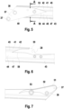
- Fig. 5:
- das proximale Ende des Mastarm-Segments aus
Fig. 3 in vergrößerter Darstellung; - Fig. 6:
- einen Ausschnitt aus dem Mastarm-Segment aus
Fig. 3 in vergrößerter Darstellung; - Fig. 7:
- das distale Ende des Mastarm-Segments aus
Fig. 3 in vergrößerter Darstellung; - Fig. 8:
- eine Befestigungsaufnahme des Mastarm-Segments aus
Fig. 3 in vergrößerter Darstellung; - Fig. 9:
- die Befestigungsaufnahme aus
Fig. 8 in einer anderen Perspektive; - Fig. 10:
- das proximale Ende des Mastarm-Segments aus
Fig. 5 in perspektivischer Darstellung; - Fig. 11:
- das distale Ende des Mastarm-Segments aus
Fig. 7 in perspektivischer Darstellung; - Fig. 12:
- einen Querschnitt entlang Linie A-A in
Fig. 5 ; - Fig. 13:
- eine Ansicht von schräg unten auf das proximale Ende des Mastarm-Segments aus
Fig. 5 ; - Fig. 14:
- das Mastarm-Ende aus
Fig. 13 ohne seitliches Verstärkungsteil; - Fig. 15:
- das Mastarm-Ende aus
Fig. 13 in einer Ansicht von unten; - Fig. 16:
- das Mastarm-Ende aus
Fig. 14 in einer Ansicht von schräg unten. - Ein in
Fig. 1 gezeigter Lastwagen 14 ist mit einer Betonpumpe 15 ausgestattet, die Flüssigbeton aus einem Vorfüllbehälter 16 durch eine Förderleitung 17 fördert. Die Förderleitung 17 erstreckt sich entlang einem Mastarm 18, der auf einem Drehkranz 19 drehbar gelagert ist. Der Mastarm 18 umfasst drei Mastarm-Segmente 20, 21, 22, die gelenkig miteinander verbunden sind. Indem die Mastarm-Segmente 20, 21, 22 über die Gelenke relativ zueinander geschwenkt werden, kann der Mastarm 18 zwischen einem eingefalteten Zustand (Fig. 1 ) und einem ausgefalteten Zustand (Fig. 2 ) wechseln. Die Förderleitung 17 erstreckt sich bis über das distale Ende des dritten Mastarm-Segments 22 hinaus, so dass der Flüssigbeton in einem von der Betonpumpe 15 entfernten Bereich ausgebracht werden kann. - Je nach Schwenkzustand des Mastarms wirken die Lasten auf die Mastarm-Segmente 20, 21, 22 in ganz unterschiedliche Richtungen. Zudem ist der Mastarm durch die stoßweise Förderung des Flüssigbetons einer hohen dynamischen Belastung ausgesetzt.
- Die Schwenkgelenke zwischen den Mastarm-Segmenten 20, 21, 22 sind so gestaltet, dass sie einen großen Schwenkwinkel ermöglichen. Im eingefalteten Zustand liegen die Mastarm-Segmente 20, 21, 22 im Wesentlichen parallel zueinander und schließen einen kleinen Winkel zwischen sich ein. In dem ausgefalteten Zustand gemäß
Fig. 2 erstrecken sich die Mastarm-Segmente 20, 21, 22 etwa in Verlängerung zueinander. - Die Gelenkkonstruktion ist in
Fig. 4 am Beispiel des Schwenkgelenks zwischen dem ersten Mastarm-Segment 20 und dem zweiten Mastarm-Segment 21 dargestellt. Die Schwenkachse 74 wird gebildet durch einen Gelenkbolzen 23, durch den ein proximales Ende des Mastarm-Segments 21 mit einem distalen Ende des Mastarm-Segments 20 verbunden ist. Benachbart zu dem Gelenkbolzen 23 ist an dem ersten Mastarm-Segment 20 ein erster Gelenkhebel 24 angeschlagen. An dem zweiten Mastarm-Segment 21 ist benachbart zu dem Gelenkbolzen 23 ein zweiter Gelenkhebel 25 angeschlagen. Die beiden Gelenkhebel sind bei 26 gelenkig miteinander verbunden. Ein Hydraulikzylinder 27 erstreckt sich von einer Aufnahme 28 an dem ersten Mastarm-Segment 20 bis zum äu-βeren Ende des ersten Gelenkhebels 24. Über die Gelenkhebel 24, 25 wird eine Hubbewegung des Hydraulikzylinders 27 in eine Schwenkbewegung zwischen den Mastarm-Segmenten 20, 21 übersetzt. - Ein in
Fig. 3 gezeigtes erfindungsgemäßes Mastarm-Segment 30 erstreckt sich von einem proximalen Ende 31 bis zu einem distalen Ende 32. Das Mastarm-Segment 30 ist als kastenförmiges Profil ausgebildet mit einem Obergurt 33, einem Untergurt 34 und zwei Seitenteilen 35, 36. Das kastenförmige Profil des Mastarm-Segments verjüngt sich vom proximalen Ende 31 bis zu der Aufnahme 28 für den Hydraulikzylinder kontinuierlich. Die beiden Seitenteile 35, 36 sowie der Obergurt 33 und der Untergurt 34 nähern sich also mit zunehmendem Abstand vom proximalen Ende 31 jeweils aneinander an. - Nahe dem proximalen Ende 31 ist das Mastarm-Segment 30 mit einem ersten Verstärkungsteil 40 verstärkt, das eine proximale Gelenkaufnahme 57 des Mastarm-Segments 30 bildet. Ausgehend von dem ersten Verstärkungsteil 40 erstreckt sich das kastenförmige Profil in Richtung des distalen Endes 32. Das kastenförmige Profil ist zusammengesetzt aus einer oberen Halbschale 41 und einer unteren Halbschale 47, die jeweils als gekantete Bleche ausgebildet sind.
- Gemäß der Querschnittsdarstellung in
Fig. 12 umfassen die beiden Seitenteile 35, 36 jeweils einen oberen Randabschnitt 42, der an den Obergurt 33 angrenzt, und einen unteren Randabschnitt 43, der an den Untergurt 34 angrenzt. Die oberen Randabschnitte 42 und die unteren Randabschnitte 43 liegen in derselben Ebene. Zwischen den Randabschnitten 42, 43 ist ein Zentralabschnitt 44 angeordnet, der einen lateralen Versatz 56 relativ zu den Randabschnitten 42, 43 aufweist. Die Seitenteile 35, 36 sind nach innen abgekantet, so dass die Zentralabschnitte 44 der beiden Seitenteile 35, 36 einen geringeren Abstand zueinander haben als die Randabschnitte 42, 43 der Seitenteile 35, 36. Zwischen dem Zentralabschnitt 44 und den Randabschnitten 42, 43 sind Übergangsabschnitte 45, 46 ausgebildet, die jeweils einen Winkel von etwa 30° mit der Ebene der Randabschnitte 42, 43 bzw. der dazu parallelen Ebene der Zentralabschnitte 44 einschließen. - Die obere Halbschale 41 umfasst den Obergurt, die oberen Randabschnitte 42, die oberen Übergangsabschnitte 45 sowie den oberen Teil der Zentralabschnitte 44 jeweils von beiden Seitenteilen 35, 36. Die untere Halbschale 47 umfasst den Untergurt 34, die unteren Randabschnitte 43, die unteren Übergangsabschnitte 46 sowie den unteren Teil der Zentralabschnitte 44 jeweils von beiden Seitenteilen 35, 36. Das obere Ende der unteren Halbschale 47 überlappt mit dem unteren Ende der oberen Halbschale 41. Am unteren Ende der oberen Halbschale 47 ist eine Schweißnaht ausgebildet, durch die die beiden Halbschalen 41, 47 miteinander verbunden sind. Die untere Halbschale 47 ist mit ihrer Endkante 55 nach innen abgekantet und bildet damit eine Beulsteife für das Kastenprofil.
- Das erste Verstärkungsteil 40 hat eine größere Materialstärke als das Kastenprofil aus den Halbschalen 41, 47, siehe
Fig. 12 . Die Außenseite des ersten Verstärkungsteils 40 fällt mit der Außenseite der oberen Randabschnitte 42 zusammen. Die Innenseite des ersten Verstärkungsteils 40 fällt mit der Außenseite der Zentralabschnitte 44 zusammen. Mit den Übergangsabschnitten 45, 46 wechselt das Kastenprofil zwischen der Außenseite und der Innenseite des ersten Verstärkungsteils 40. - Die Übergangsabschnitte 45, 46 sowie die Randabschnitte 42, 43 sind auf Stoß mit dem ersten Verstärkungsteil 40 verschweißt. Die Zentralabschnitte 44 überlappen mit dem ersten Verstärkungsteil 40. Die Verbindung zwischen dem ersten Verstärkungsteil 40 und den Zentralabschnitten 44 wird durch eine umlaufende Schweißnaht um das erste Verstärkungsteil 40 herum gebildet.
- Gemäß
Fig. 5 ,10 ist in dem ersten Verstärkungsteil 40 eine Gelenkbohrung 37 ausgebildet. Die Gelenkbohrung nimmt den Gelenkbolzen 23 auf, der das Mastarm-Segment 30 mit einem benachbarten Mastarm-Segment verbindet. Neben der Gelenkbohrung 37 kann der Gelenkhebel 25 angeschlossen werden. Entsprechend umfasst das Mastarm-Segment 30 nahe seinem distalen Ende eine weitere Gelenkbohrung 37 sowie einen weiteren Stehbolzen 38, an den ein Gelenkhebel 24 angeschlossen werden kann. - Das Mastarm-Segment 30 umfasst ein weiteres Verstärkungsteil 50, das die Aufnahme 28 für den Hydraulikzylinder bildet. Das weitere Verstärkungsteil 50 hat dieselbe Materialstärke wie das erste Verstärkungsteil 40 und fügt sich auf die gleiche Weise in die Kontur der oberen Halbschale 41 ein. Das weitere Verstärkungsteil 50 überlappt also mit den Zentralabschnitten 44 der Seitenteile 35, 36 und ist dort durch eine umlaufende Schweißnaht mit der oberen Halbschale 41 verbunden. Der obere Übergangsabschnitt 45 sowie der obere Randabschnitt 42 sind auf Stoß mit dem weiteren Verstärkungsteil 50 verschweißt.
- Die in den
Fig. 7 und11 gezeigte distale Gelenkaufnahme 51 umfasst ein Verstärkungsblech 52, das auf das Blech des Kastenprofils aufgedoppelt ist. Die Verbindung zwischen dem Verstärkungsblech 52 und dem Kastenprofil wird durch eine umlaufende Schweißnaht gebildet, die sich über den Umfang des Verstärkungsblechs 52 erstreckt. Die Gelenkaufnahme 51 umfasst eine Gelenkbohrung 37, die den Gelenkbolzen 23 für die Verbindung mit einem benachbarten Mastarm-Segment aufnimmt. Neben der Gelenkbohrung 37 ist ein Stehbolzen 38 angeordnet, an dem der Gelenkhebel 25 angeschlossen wird. - Das Mastarm-Segment umfasst gemäß
Fig. 3 eine Mehrzahl von Befestigungsaufnahmen 53 zum Anbringen von Haltern (nicht dargestellt) für die Förderleitung 17. Eine erste Befestigungsaufnahme 53 ist mit dem ersten Verstärkungsteil 40 verbunden. In den Seitenteilen 35, 36 des Kastenprofils sind zwei weitere Befestigungsaufnahmen 53 angeordnet. Eine vierte Befestigungsaufnahme 53 ist nahe der distalen Gelenkaufnahme 51 angeordnet. - Gemäß den
Fig. 8 und 9 bildet die Befestigungsaufnahme 53 eine Querverbindung 54 zwischen dem ersten Seitenteil 35 und dem zweiten Seitenteil 36. Die Querverbindung 54 wird durch ein Rohrstück gebildet, das mit den Zentralabschnitten 44 beider Seitenteile 35, 36 verschweißt ist. Indem die Seitenteile 35, 36 durch das Rohrstück 54 in einem festen Abstand zueinander gehalten werden, wirken die Befestigungsaufnahmen 53 einer Beulverformung des Mastarm-Segments 30 entgegen. - Auf der Seite des ersten Seitenteils 35 endet das Rohrstück 54 als Rohrstummel, der leicht gegenüber dem Zentralabschnitt 44 des Seitenteils 35 vorspringt. Auf der Seite des zweiten Seitenteils 36 ist die Befestigungsaufnahme 53 mit vier Gewindebohrungen versehen, an denen der Halter für die Förderleitung festgeschraubt werden kann.
- Gemäß
Fig. 13 wird der Untergurt 34 durch ein Blech gebildet, das in Längsrichtung eben ist und dass in Querrichtung durch vier Abkantungen 60 eine nach außen gewölbte Form hat. Das proximale Ende 61 des Untergurts wird gebildet durch zwei seitlich auslaufende Spitzen mit einer dazwischenliegenden abgerundeten Ausnehmung. Die Seitenkanten des Untergurts 34 sind bis in die Spitzen hinein mit den Verstärkungsteilen 40, 70 verschweißt. Das proximale Ende 61 des Untergurts liegt in der Mitte der Verstärkungsteile 40, 70 und ist damit beabstandet von der in Verlängerung des Untergurts 34 liegenden Kante 75 der Verstärkungsteile 40, 70. - Die Gelenkbohrung 37 erstreckt sich innerhalb eines Rohrstücks, dass den Gelenkanschluss 62 bildet. Das Rohrstück ist mit seinem gesamten Querschnitt unterhalb der Ebene 63 des Untergurts 34 angeordnet, so dass keine direkte Verbindung zwischen dem Untergurt 34 und dem Gelenkanschluss 62 möglich ist.
- Zwischen dem Gelenkanschluss 62 und dem Untergurt 34 erstreckt sich ein Übergangsstück 64, das in einer Verbindung 65 mit dem Untergurt 34 und in einer Verbindung 66 mit dem Gelenkanschluss 62 steht. Die Verbindung 66 zum Gelenkanschluss 62 hat einen größeren Abstand zu der Ebene 63 des Untergurts als die Schwenkachse 74. Das Übergangsstück 64 schließt einen Winkel 67 von etwa 20° mit der Ebene 63 des Untergurts ein. Dieser Winkel 67 ist etwas größer als der Winkel 68, den die Unterkante 69 des Verstärkungsteils 40 mit der Ebene 63 des Untergurts einschließt. Bezogen auf eine gegebene Längsposition in der Ebene 63 des Untergurts 34 ist der Abstand 72 zwischen der Unterkante 69 des Verstärkungsteils 40 und der Ebene 63 größer als der Abstand 71 zwischen dem Übergangsstück 64 und der Ebene 63. Der Abstand 76 zwischen der Verbindung 66 zum Gelenkanschluss 62 und der Ebene 63 ist größer als der Abstand 77 zwischen der Schwenkachse 74 und der Ebene 63.
Claims (9)
- Mastarm-Segment für eine Betonpumpe, mit einem Obergurt (33), einem Untergurt (34) und zwei den Obergurt (33) und den Untergurt (34) verbindenden Seitenteilen (35, 36), wobei das Mastarm-Segment (30) einen Gelenkanschluss (62) umfasst, der eine Schwenkachse (74) für eine Schwenkverbindung zwischen dem Mastarm-Segment (21) und einer benachbarten Struktur (20) definiert, wobei die Schwenkachse (74) unterhalb der Ebene (63) des Untergurts (34) angeordnet ist, wobei zwischen dem Untergurt (34) und dem Gelenkanschluss (62) ein Übergangsstück (64) angeordnet ist, wobei eine erste Verbindung (65) zwischen dem Übergangsstück (64) und dem Untergurt (34) ausgebildet ist, wobei die erste Verbindung (65) vom benachbarten Ende (61) des Untergurts (34) beabstandet ist, wobei das Übergangsstück (64) eingeschlossen ist zwischen einem ersten Verstärkungsteil (40) und einem zweiten Verstärkungsteil (70), die seitlich an das Übergangsstück (64) angrenzen,
dadurch gekennzeichnet,
dass die Verstärkungsteile (40, 70) jeweils eine Unterkante (69) aufweisen, die sich von dem Gelenkanschluss (62) zu dem Untergurt (34) erstreckt und wobei die Unterkanten (69) einen Winkel (68) mit der Ebene (63) des Untergurts (34) einschließen, der kleiner ist als der Winkel (67), den das Übergangsstück (64) mit der Ebene (63) des Untergurts (34) einschließt. - Mastarm-Segment nach Anspruch 1, dadurch gekennzeichnet, dass der Untergurt (34) mit Abkantungen (60) versehen ist.
- Mastarm-Segment nach Anspruch 2, dadurch gekennzeichnet, dass der Untergurt (34) in Querrichtung gewölbt ist.
- Mastarm-Segment nach einem der Ansprüche 1 bis 3, dadurch gekennzeichnet, dass das Übergangsstück (64) einen Winkel zwischen 5° und 50°, vorzugsweise zwischen 10° und 40° mit der Ebene (63) des Untergurts (34) einschließt.
- Mastarm-Segment nach einem der Ansprüche 1 bis 4, dadurch gekennzeichnet, dass das Übergangsstück (64) sich über die gesamte Breite des Untergurts (34) erstreckt.
- Mastarm-Segment nach einem der Ansprüche 1 bis 5, dadurch gekennzeichnet, dass das Übergangsstück (64) mit dem Untergurt (34) und/oder mit dem Gelenkanschluss (62) verschweißt ist.
- Mastarm-Segment nach einem der Ansprüche 1 bis 6, dadurch gekennzeichnet, dass zwischen dem Übergangsstück (64) und dem Gelenkanschluss (62) eine zweite Verbindung (66) ausgebildet ist und dass die zweite Verbindung (66) einen Abstand (76) zu der Ebene (63) des Untergurts (34) hat, der größer ist als der Abstand (77) zwischen der Schwenkachse (74) und der Ebene (63) des Untergurts (34).
- Mastarm-Segment nach einem der Ansprüche 1 bis 7, dadurch gekennzeichnet, dass bezogen auf eine gegebene Längsposition des Untergurts (34) der Abstand (72) zwischen der Unterkante (69) des Verstärkungsteils (40, 70) und der Ebene (63) des Untergurts (34) größer ist als der Abstand (71)zwischen dem Übergangsstück (64) und der Ebene (63) des Untergurts (34).
- Mastarm-Segment nach einem der Ansprüche 1 bis 8, dadurch gekennzeichnet, dass das Ende (61) des Untergurts (34) zwischen den Verstärkungsteilen (40, 70) eingeschlossen ist und dass das Ende (61) des Untergurts (34) von einer in Verlängerung des Untergurts (34) liegenden Kante (75) des Verstärkungsteils (40, 70) beabstandet ist.
Applications Claiming Priority (2)
| Application Number | Priority Date | Filing Date | Title |
|---|---|---|---|
| EP21170838.3A EP4083345A1 (de) | 2021-04-28 | 2021-04-28 | Mastarm-segment für eine betonpumpe |
| PCT/EP2022/060664 WO2022229013A1 (de) | 2021-04-28 | 2022-04-22 | Mastarm-segment für eine betonpumpe |
Publications (2)
| Publication Number | Publication Date |
|---|---|
| EP4330493A1 EP4330493A1 (de) | 2024-03-06 |
| EP4330493B1 true EP4330493B1 (de) | 2025-01-22 |
Family
ID=75728649
Family Applications (2)
| Application Number | Title | Priority Date | Filing Date |
|---|---|---|---|
| EP21170838.3A Withdrawn EP4083345A1 (de) | 2021-04-28 | 2021-04-28 | Mastarm-segment für eine betonpumpe |
| EP22724102.3A Active EP4330493B1 (de) | 2021-04-28 | 2022-04-22 | Mastarm-segment für eine betonpumpe |
Family Applications Before (1)
| Application Number | Title | Priority Date | Filing Date |
|---|---|---|---|
| EP21170838.3A Withdrawn EP4083345A1 (de) | 2021-04-28 | 2021-04-28 | Mastarm-segment für eine betonpumpe |
Country Status (5)
| Country | Link |
|---|---|
| US (1) | US20240240475A1 (de) |
| EP (2) | EP4083345A1 (de) |
| KR (1) | KR20230175250A (de) |
| CN (1) | CN117377806A (de) |
| WO (1) | WO2022229013A1 (de) |
Family Cites Families (8)
| Publication number | Priority date | Publication date | Assignee | Title |
|---|---|---|---|---|
| CN101712439B (zh) * | 2009-11-27 | 2012-07-04 | 三一汽车制造有限公司 | 起重机转场辅助装置、运输拖车及拆装起重机的方法 |
| US8739988B2 (en) * | 2010-09-20 | 2014-06-03 | Manitowoc Crane Companies, Llc | Pinned connection system for crane column segments |
| US9139409B2 (en) * | 2013-03-12 | 2015-09-22 | Oshkosh Corporation | Weighted boom assembly |
| CN205036090U (zh) * | 2015-10-08 | 2016-02-17 | 三一汽车制造有限公司 | 油缸座结构及工程机械 |
| DE102016009811B4 (de) * | 2016-07-21 | 2019-05-16 | Liebherr-Werk Ehingen Gmbh | Teleskopausleger mit räumlicher Abspannung |
| CN207554068U (zh) * | 2017-10-20 | 2018-06-29 | 青岛青科重工有限公司 | 一种混凝土湿喷台车臂架 |
| CN110203833B (zh) * | 2019-04-16 | 2020-09-11 | 上海亿锤机械科技有限公司 | 一种折叠式正面吊运机吊具 |
| CN110984578B (zh) * | 2019-11-07 | 2020-11-06 | 中联重科股份有限公司 | 臂架、工程机械和臂架的制造方法 |
-
2021
- 2021-04-28 EP EP21170838.3A patent/EP4083345A1/de not_active Withdrawn
-
2022
- 2022-04-22 WO PCT/EP2022/060664 patent/WO2022229013A1/de not_active Ceased
- 2022-04-22 US US18/556,750 patent/US20240240475A1/en active Pending
- 2022-04-22 EP EP22724102.3A patent/EP4330493B1/de active Active
- 2022-04-22 CN CN202280031758.4A patent/CN117377806A/zh active Pending
- 2022-04-22 KR KR1020237039851A patent/KR20230175250A/ko active Pending
Also Published As
| Publication number | Publication date |
|---|---|
| EP4083345A1 (de) | 2022-11-02 |
| US20240240475A1 (en) | 2024-07-18 |
| CN117377806A (zh) | 2024-01-09 |
| EP4330493A1 (de) | 2024-03-06 |
| WO2022229013A1 (de) | 2022-11-03 |
| KR20230175250A (ko) | 2023-12-29 |
Similar Documents
| Publication | Publication Date | Title |
|---|---|---|
| EP2297020B1 (de) | Fahrzeugkran mit schlauchführung | |
| EP0376417A1 (de) | Mehrschnittige Bolzenverbindung | |
| EP3728760A1 (de) | Betonpumpen-mastarm-segment mit in längsrichtung variabler blechstärke und verfahren zum herstellen eines solchen betonpumpe-mastarm-segments | |
| EP3456888B1 (de) | Baggerausleger und bagger | |
| DE2831565A1 (de) | Quergliedanordnung | |
| EP3456887B1 (de) | Baggerausleger und bagger | |
| EP4298297B1 (de) | Mastarm-segment und verfahren zum herstellen eines mastarm-segments | |
| EP3477018B1 (de) | Hohler zweipunkthebel | |
| EP4083345A1 (de) | Mastarm-segment für eine betonpumpe | |
| DE102015104139A1 (de) | Drehschemel für einen Großmanipulator | |
| EP3717716B1 (de) | Kröpfung mit gekantetem schottblech | |
| EP3717717A1 (de) | Mastsegment eines knickmastes mit kröpfung | |
| EP3754117B1 (de) | Baggerstiel | |
| EP3207193B1 (de) | Mastarm und betonverteilermast | |
| DE102021120617A1 (de) | Mastarm-Segment für eine Betonpumpe und Verfahren zum Herstellen eines Mastarm-Segments | |
| WO2019121634A1 (de) | Mastarm-segment mit mehrdimensionalem formteil und verfahren zum herstellen eines mastarm-segments | |
| DE102017125862A1 (de) | Schwenkbarer Mast mit Verstärkungslagen | |
| DE3125968A1 (de) | Scharnierarm | |
| AT502507B1 (de) | Schwinge für ein mit einem arbeitsgerät ausgebildetes fahrzeug, insbesondere für einen traktor | |
| EP4259884A1 (de) | Montagevorrichtung | |
| DE19713487C1 (de) | Vorrichtung zur Zugentlastung bei Auslegern an Arbeitsausrüstungen von Baggern | |
| WO2019077042A1 (de) | Doppelwandiges mastsegment |
Legal Events
| Date | Code | Title | Description |
|---|---|---|---|
| STAA | Information on the status of an ep patent application or granted ep patent |
Free format text: STATUS: UNKNOWN |
|
| STAA | Information on the status of an ep patent application or granted ep patent |
Free format text: STATUS: THE INTERNATIONAL PUBLICATION HAS BEEN MADE |
|
| PUAI | Public reference made under article 153(3) epc to a published international application that has entered the european phase |
Free format text: ORIGINAL CODE: 0009012 |
|
| STAA | Information on the status of an ep patent application or granted ep patent |
Free format text: STATUS: REQUEST FOR EXAMINATION WAS MADE |
|
| 17P | Request for examination filed |
Effective date: 20231030 |
|
| AK | Designated contracting states |
Kind code of ref document: A1 Designated state(s): AL AT BE BG CH CY CZ DE DK EE ES FI FR GB GR HR HU IE IS IT LI LT LU LV MC MK MT NL NO PL PT RO RS SE SI SK SM TR |
|
| DAV | Request for validation of the european patent (deleted) | ||
| DAX | Request for extension of the european patent (deleted) | ||
| GRAP | Despatch of communication of intention to grant a patent |
Free format text: ORIGINAL CODE: EPIDOSNIGR1 |
|
| STAA | Information on the status of an ep patent application or granted ep patent |
Free format text: STATUS: GRANT OF PATENT IS INTENDED |
|
| INTG | Intention to grant announced |
Effective date: 20241008 |
|
| GRAS | Grant fee paid |
Free format text: ORIGINAL CODE: EPIDOSNIGR3 |
|
| GRAA | (expected) grant |
Free format text: ORIGINAL CODE: 0009210 |
|
| STAA | Information on the status of an ep patent application or granted ep patent |
Free format text: STATUS: THE PATENT HAS BEEN GRANTED |
|
| AK | Designated contracting states |
Kind code of ref document: B1 Designated state(s): AL AT BE BG CH CY CZ DE DK EE ES FI FR GB GR HR HU IE IS IT LI LT LU LV MC MK MT NL NO PL PT RO RS SE SI SK SM TR |
|
| REG | Reference to a national code |
Ref country code: GB Ref legal event code: FG4D Free format text: NOT ENGLISH |
|
| REG | Reference to a national code |
Ref country code: CH Ref legal event code: EP |
|
| REG | Reference to a national code |
Ref country code: IE Ref legal event code: FG4D Free format text: LANGUAGE OF EP DOCUMENT: GERMAN |
|
| REG | Reference to a national code |
Ref country code: DE Ref legal event code: R096 Ref document number: 502022002724 Country of ref document: DE |
|
| REG | Reference to a national code |
Ref country code: NL Ref legal event code: MP Effective date: 20250122 |
|
| PG25 | Lapsed in a contracting state [announced via postgrant information from national office to epo] |
Ref country code: NL Free format text: LAPSE BECAUSE OF FAILURE TO SUBMIT A TRANSLATION OF THE DESCRIPTION OR TO PAY THE FEE WITHIN THE PRESCRIBED TIME-LIMIT Effective date: 20250122 |
|
| PG25 | Lapsed in a contracting state [announced via postgrant information from national office to epo] |
Ref country code: RS Free format text: LAPSE BECAUSE OF FAILURE TO SUBMIT A TRANSLATION OF THE DESCRIPTION OR TO PAY THE FEE WITHIN THE PRESCRIBED TIME-LIMIT Effective date: 20250422 |
|
| PG25 | Lapsed in a contracting state [announced via postgrant information from national office to epo] |
Ref country code: FI Free format text: LAPSE BECAUSE OF FAILURE TO SUBMIT A TRANSLATION OF THE DESCRIPTION OR TO PAY THE FEE WITHIN THE PRESCRIBED TIME-LIMIT Effective date: 20250122 |
|
| PG25 | Lapsed in a contracting state [announced via postgrant information from national office to epo] |
Ref country code: PL Free format text: LAPSE BECAUSE OF FAILURE TO SUBMIT A TRANSLATION OF THE DESCRIPTION OR TO PAY THE FEE WITHIN THE PRESCRIBED TIME-LIMIT Effective date: 20250122 |
|
| PGFP | Annual fee paid to national office [announced via postgrant information from national office to epo] |
Ref country code: DE Payment date: 20250423 Year of fee payment: 4 |
|
| PG25 | Lapsed in a contracting state [announced via postgrant information from national office to epo] |
Ref country code: ES Free format text: LAPSE BECAUSE OF FAILURE TO SUBMIT A TRANSLATION OF THE DESCRIPTION OR TO PAY THE FEE WITHIN THE PRESCRIBED TIME-LIMIT Effective date: 20250122 |
|
| REG | Reference to a national code |
Ref country code: LT Ref legal event code: MG9D |
|
| PG25 | Lapsed in a contracting state [announced via postgrant information from national office to epo] |
Ref country code: NO Free format text: LAPSE BECAUSE OF FAILURE TO SUBMIT A TRANSLATION OF THE DESCRIPTION OR TO PAY THE FEE WITHIN THE PRESCRIBED TIME-LIMIT Effective date: 20250422 Ref country code: IS Free format text: LAPSE BECAUSE OF FAILURE TO SUBMIT A TRANSLATION OF THE DESCRIPTION OR TO PAY THE FEE WITHIN THE PRESCRIBED TIME-LIMIT Effective date: 20250522 |
|
| PGFP | Annual fee paid to national office [announced via postgrant information from national office to epo] |
Ref country code: IT Payment date: 20250430 Year of fee payment: 4 |
|
| PG25 | Lapsed in a contracting state [announced via postgrant information from national office to epo] |
Ref country code: HR Free format text: LAPSE BECAUSE OF FAILURE TO SUBMIT A TRANSLATION OF THE DESCRIPTION OR TO PAY THE FEE WITHIN THE PRESCRIBED TIME-LIMIT Effective date: 20250122 |
|
| PG25 | Lapsed in a contracting state [announced via postgrant information from national office to epo] |
Ref country code: LV Free format text: LAPSE BECAUSE OF FAILURE TO SUBMIT A TRANSLATION OF THE DESCRIPTION OR TO PAY THE FEE WITHIN THE PRESCRIBED TIME-LIMIT Effective date: 20250122 Ref country code: PT Free format text: LAPSE BECAUSE OF FAILURE TO SUBMIT A TRANSLATION OF THE DESCRIPTION OR TO PAY THE FEE WITHIN THE PRESCRIBED TIME-LIMIT Effective date: 20250522 |
|
| PG25 | Lapsed in a contracting state [announced via postgrant information from national office to epo] |
Ref country code: GR Free format text: LAPSE BECAUSE OF FAILURE TO SUBMIT A TRANSLATION OF THE DESCRIPTION OR TO PAY THE FEE WITHIN THE PRESCRIBED TIME-LIMIT Effective date: 20250423 Ref country code: BG Free format text: LAPSE BECAUSE OF FAILURE TO SUBMIT A TRANSLATION OF THE DESCRIPTION OR TO PAY THE FEE WITHIN THE PRESCRIBED TIME-LIMIT Effective date: 20250122 |
|
| PGFP | Annual fee paid to national office [announced via postgrant information from national office to epo] |
Ref country code: AT Payment date: 20250721 Year of fee payment: 4 |
|
| PGFP | Annual fee paid to national office [announced via postgrant information from national office to epo] |
Ref country code: TR Payment date: 20250414 Year of fee payment: 4 |
|
| PG25 | Lapsed in a contracting state [announced via postgrant information from national office to epo] |
Ref country code: SE Free format text: LAPSE BECAUSE OF FAILURE TO SUBMIT A TRANSLATION OF THE DESCRIPTION OR TO PAY THE FEE WITHIN THE PRESCRIBED TIME-LIMIT Effective date: 20250122 |
|
| PG25 | Lapsed in a contracting state [announced via postgrant information from national office to epo] |
Ref country code: SM Free format text: LAPSE BECAUSE OF FAILURE TO SUBMIT A TRANSLATION OF THE DESCRIPTION OR TO PAY THE FEE WITHIN THE PRESCRIBED TIME-LIMIT Effective date: 20250122 |
|
| PG25 | Lapsed in a contracting state [announced via postgrant information from national office to epo] |
Ref country code: DK Free format text: LAPSE BECAUSE OF FAILURE TO SUBMIT A TRANSLATION OF THE DESCRIPTION OR TO PAY THE FEE WITHIN THE PRESCRIBED TIME-LIMIT Effective date: 20250122 |
|
| PG25 | Lapsed in a contracting state [announced via postgrant information from national office to epo] |
Ref country code: EE Free format text: LAPSE BECAUSE OF FAILURE TO SUBMIT A TRANSLATION OF THE DESCRIPTION OR TO PAY THE FEE WITHIN THE PRESCRIBED TIME-LIMIT Effective date: 20250122 Ref country code: CZ Free format text: LAPSE BECAUSE OF FAILURE TO SUBMIT A TRANSLATION OF THE DESCRIPTION OR TO PAY THE FEE WITHIN THE PRESCRIBED TIME-LIMIT Effective date: 20250122 |
|
| REG | Reference to a national code |
Ref country code: DE Ref legal event code: R097 Ref document number: 502022002724 Country of ref document: DE |
|
| PG25 | Lapsed in a contracting state [announced via postgrant information from national office to epo] |
Ref country code: RO Free format text: LAPSE BECAUSE OF FAILURE TO SUBMIT A TRANSLATION OF THE DESCRIPTION OR TO PAY THE FEE WITHIN THE PRESCRIBED TIME-LIMIT Effective date: 20250122 |
|
| PG25 | Lapsed in a contracting state [announced via postgrant information from national office to epo] |
Ref country code: SK Free format text: LAPSE BECAUSE OF FAILURE TO SUBMIT A TRANSLATION OF THE DESCRIPTION OR TO PAY THE FEE WITHIN THE PRESCRIBED TIME-LIMIT Effective date: 20250122 |
|
| REG | Reference to a national code |
Ref country code: CH Ref legal event code: H13 Free format text: ST27 STATUS EVENT CODE: U-0-0-H10-H13 (AS PROVIDED BY THE NATIONAL OFFICE) Effective date: 20251125 |
|
| PLBE | No opposition filed within time limit |
Free format text: ORIGINAL CODE: 0009261 |
|
| STAA | Information on the status of an ep patent application or granted ep patent |
Free format text: STATUS: NO OPPOSITION FILED WITHIN TIME LIMIT |
|
| PG25 | Lapsed in a contracting state [announced via postgrant information from national office to epo] |
Ref country code: LU Free format text: LAPSE BECAUSE OF NON-PAYMENT OF DUE FEES Effective date: 20250422 |
|
| PG25 | Lapsed in a contracting state [announced via postgrant information from national office to epo] |
Ref country code: MC Free format text: LAPSE BECAUSE OF FAILURE TO SUBMIT A TRANSLATION OF THE DESCRIPTION OR TO PAY THE FEE WITHIN THE PRESCRIBED TIME-LIMIT Effective date: 20250122 |
|
| REG | Reference to a national code |
Ref country code: BE Ref legal event code: MM Effective date: 20250430 |
|
| 26N | No opposition filed |
Effective date: 20251023 |
|
| PG25 | Lapsed in a contracting state [announced via postgrant information from national office to epo] |
Ref country code: FR Free format text: LAPSE BECAUSE OF NON-PAYMENT OF DUE FEES Effective date: 20250430 |
|
| PG25 | Lapsed in a contracting state [announced via postgrant information from national office to epo] |
Ref country code: BE Free format text: LAPSE BECAUSE OF NON-PAYMENT OF DUE FEES Effective date: 20250430 |
|
| PG25 | Lapsed in a contracting state [announced via postgrant information from national office to epo] |
Ref country code: CH Free format text: LAPSE BECAUSE OF NON-PAYMENT OF DUE FEES Effective date: 20250430 |
|
| PG25 | Lapsed in a contracting state [announced via postgrant information from national office to epo] |
Ref country code: IE Free format text: LAPSE BECAUSE OF NON-PAYMENT OF DUE FEES Effective date: 20250422 |