EP4330165B1 - Fördervorrichtung zum fördern von lebensmitteln und wärmebehandlungsvorrichtung - Google Patents
Fördervorrichtung zum fördern von lebensmitteln und wärmebehandlungsvorrichtung Download PDFInfo
- Publication number
- EP4330165B1 EP4330165B1 EP22844264.6A EP22844264A EP4330165B1 EP 4330165 B1 EP4330165 B1 EP 4330165B1 EP 22844264 A EP22844264 A EP 22844264A EP 4330165 B1 EP4330165 B1 EP 4330165B1
- Authority
- EP
- European Patent Office
- Prior art keywords
- conveying apparatus
- container
- conveyor
- pin
- cup
- Prior art date
- Legal status (The legal status is an assumption and is not a legal conclusion. Google has not performed a legal analysis and makes no representation as to the accuracy of the status listed.)
- Active
Links
Images


Classifications
-
- A—HUMAN NECESSITIES
- A23—FOODS OR FOODSTUFFS; TREATMENT THEREOF, NOT COVERED BY OTHER CLASSES
- A23L—FOODS, FOODSTUFFS OR NON-ALCOHOLIC BEVERAGES, NOT OTHERWISE PROVIDED FOR; PREPARATION OR TREATMENT THEREOF
- A23L5/00—Preparation or treatment of foods or foodstuffs, in general; Food or foodstuffs obtained thereby; Materials therefor
- A23L5/10—General methods of cooking foods, e.g. by roasting or frying
- A23L5/17—General methods of cooking foods, e.g. by roasting or frying in a gaseous atmosphere with forced air or gas circulation, in vacuum or under pressure
-
- B—PERFORMING OPERATIONS; TRANSPORTING
- B65—CONVEYING; PACKING; STORING; HANDLING THIN OR FILAMENTARY MATERIAL
- B65G—TRANSPORT OR STORAGE DEVICES, e.g. CONVEYORS FOR LOADING OR TIPPING, SHOP CONVEYOR SYSTEMS OR PNEUMATIC TUBE CONVEYORS
- B65G17/00—Conveyors having an endless traction element, e.g. a chain, transmitting movement to a continuous or substantially-continuous load-carrying surface or to a series of individual load-carriers; Endless-chain conveyors in which the chains form the load-carrying surface
- B65G17/06—Conveyors having an endless traction element, e.g. a chain, transmitting movement to a continuous or substantially-continuous load-carrying surface or to a series of individual load-carriers; Endless-chain conveyors in which the chains form the load-carrying surface having a load-carrying surface formed by a series of interconnected, e.g. longitudinal, links, plates, or platforms
- B65G17/067—Conveyors having an endless traction element, e.g. a chain, transmitting movement to a continuous or substantially-continuous load-carrying surface or to a series of individual load-carriers; Endless-chain conveyors in which the chains form the load-carrying surface having a load-carrying surface formed by a series of interconnected, e.g. longitudinal, links, plates, or platforms the load carrying surface being formed by plates or platforms attached to more than one traction element
-
- B—PERFORMING OPERATIONS; TRANSPORTING
- B65—CONVEYING; PACKING; STORING; HANDLING THIN OR FILAMENTARY MATERIAL
- B65G—TRANSPORT OR STORAGE DEVICES, e.g. CONVEYORS FOR LOADING OR TIPPING, SHOP CONVEYOR SYSTEMS OR PNEUMATIC TUBE CONVEYORS
- B65G17/00—Conveyors having an endless traction element, e.g. a chain, transmitting movement to a continuous or substantially-continuous load-carrying surface or to a series of individual load-carriers; Endless-chain conveyors in which the chains form the load-carrying surface
- B65G17/12—Conveyors having an endless traction element, e.g. a chain, transmitting movement to a continuous or substantially-continuous load-carrying surface or to a series of individual load-carriers; Endless-chain conveyors in which the chains form the load-carrying surface comprising a series of individual load-carriers fixed, or normally fixed, relative to traction element
- B65G17/123—Conveyors having an endless traction element, e.g. a chain, transmitting movement to a continuous or substantially-continuous load-carrying surface or to a series of individual load-carriers; Endless-chain conveyors in which the chains form the load-carrying surface comprising a series of individual load-carriers fixed, or normally fixed, relative to traction element arranged to keep the load-carriers horizontally during at least a part of the conveyor run
-
- B—PERFORMING OPERATIONS; TRANSPORTING
- B65—CONVEYING; PACKING; STORING; HANDLING THIN OR FILAMENTARY MATERIAL
- B65G—TRANSPORT OR STORAGE DEVICES, e.g. CONVEYORS FOR LOADING OR TIPPING, SHOP CONVEYOR SYSTEMS OR PNEUMATIC TUBE CONVEYORS
- B65G17/00—Conveyors having an endless traction element, e.g. a chain, transmitting movement to a continuous or substantially-continuous load-carrying surface or to a series of individual load-carriers; Endless-chain conveyors in which the chains form the load-carrying surface
- B65G17/16—Conveyors having an endless traction element, e.g. a chain, transmitting movement to a continuous or substantially-continuous load-carrying surface or to a series of individual load-carriers; Endless-chain conveyors in which the chains form the load-carrying surface comprising individual load-carriers which are pivotally mounted, e.g. for free-swinging movement
- B65G17/18—Conveyors having an endless traction element, e.g. a chain, transmitting movement to a continuous or substantially-continuous load-carrying surface or to a series of individual load-carriers; Endless-chain conveyors in which the chains form the load-carrying surface comprising individual load-carriers which are pivotally mounted, e.g. for free-swinging movement and move in contact with a guiding surface
-
- B—PERFORMING OPERATIONS; TRANSPORTING
- B65—CONVEYING; PACKING; STORING; HANDLING THIN OR FILAMENTARY MATERIAL
- B65G—TRANSPORT OR STORAGE DEVICES, e.g. CONVEYORS FOR LOADING OR TIPPING, SHOP CONVEYOR SYSTEMS OR PNEUMATIC TUBE CONVEYORS
- B65G17/00—Conveyors having an endless traction element, e.g. a chain, transmitting movement to a continuous or substantially-continuous load-carrying surface or to a series of individual load-carriers; Endless-chain conveyors in which the chains form the load-carrying surface
- B65G17/30—Details; Auxiliary devices
- B65G17/32—Individual load-carriers
- B65G17/36—Individual load-carriers having concave surfaces, e.g. buckets
-
- B—PERFORMING OPERATIONS; TRANSPORTING
- B65—CONVEYING; PACKING; STORING; HANDLING THIN OR FILAMENTARY MATERIAL
- B65G—TRANSPORT OR STORAGE DEVICES, e.g. CONVEYORS FOR LOADING OR TIPPING, SHOP CONVEYOR SYSTEMS OR PNEUMATIC TUBE CONVEYORS
- B65G17/00—Conveyors having an endless traction element, e.g. a chain, transmitting movement to a continuous or substantially-continuous load-carrying surface or to a series of individual load-carriers; Endless-chain conveyors in which the chains form the load-carrying surface
- B65G17/30—Details; Auxiliary devices
- B65G17/38—Chains or like traction elements; Connections between traction elements and load-carriers
- B65G17/42—Attaching load carriers to traction elements
-
- B—PERFORMING OPERATIONS; TRANSPORTING
- B65—CONVEYING; PACKING; STORING; HANDLING THIN OR FILAMENTARY MATERIAL
- B65G—TRANSPORT OR STORAGE DEVICES, e.g. CONVEYORS FOR LOADING OR TIPPING, SHOP CONVEYOR SYSTEMS OR PNEUMATIC TUBE CONVEYORS
- B65G17/00—Conveyors having an endless traction element, e.g. a chain, transmitting movement to a continuous or substantially-continuous load-carrying surface or to a series of individual load-carriers; Endless-chain conveyors in which the chains form the load-carrying surface
- B65G17/30—Details; Auxiliary devices
- B65G17/48—Controlling attitudes of load-carriers during movement
-
- B—PERFORMING OPERATIONS; TRANSPORTING
- B65—CONVEYING; PACKING; STORING; HANDLING THIN OR FILAMENTARY MATERIAL
- B65G—TRANSPORT OR STORAGE DEVICES, e.g. CONVEYORS FOR LOADING OR TIPPING, SHOP CONVEYOR SYSTEMS OR PNEUMATIC TUBE CONVEYORS
- B65G2201/00—Indexing codes relating to handling devices, e.g. conveyors, characterised by the type of product or load being conveyed or handled
- B65G2201/02—Articles
- B65G2201/0202—Agricultural and processed food products
Definitions
- the present invention relates to a conveying apparatus for conveying food products and a heat treatment apparatus.
- the present invention finds application in the food industry, in particular to convey food products through treatment apparatus, such as fryer, oven, etc.
- the predefined path usually comprises a plurality of curves and height changes with respect to the floor.
- the distance between the rows serves to avoid the risk of collision during the rotation around the sprocket wheels.
- a gap between the rows is generally guaranteed in the prior art solutions.
- Document JP S60 196160 A discloses a conveying apparatus for conveying food products according to the preamble of claim 1.
- the technical task underlying the present invention is to propose a conveying apparatus for conveying food products and a heat treatment apparatus which overcome the drawbacks in the prior art as described above.
- an object of the present invention is to provide a conveying apparatus for conveying food products, which allows containers to be kept close together while avoiding the risk of collision.
- Another object of the present invention is to propose a conveying apparatus and a heat treatment apparatus able to convey and heat food products having diameter in the order of about one millimetre.
- first pin and the second pin of each container are slidably mounted within the bores of one pair of supports.
- first pin and the second pin of each container are axially rotatably mounted within the bores of one pair of supports.
- the extension of each bore is larger than the cross-section of the pins.
- the bore has an elongated development in a direction that is inclined with respect to a transport direction of the conveyor.
- the bore has an elongated development in a direction substantially orthogonal to the transport direction of the conveyor.
- the first pin of each container is axially retractable with respect to the corresponding container.
- the conveyor comprises a plurality of sprockets on which the endless chains are mounted.
- the conveyor comprises first guiding means arranged at least at one sprocket and configured to engage the pins of each container and keep them outside the pitch diameter of the sprocket during the rotation of the container around the sprocket.
- the cup-shaped receptacle comprises a perforated sheet with a plurality of through-holes, the perforated sheet being arranged to define a bottom of the cup-shaped receptacle for resting the food product.
- the through-holes have a diameter of between 0.5 and 3 mm.
- the ratio between empty and full spaces of the perforated sheet is between 0.30 and 0.70.
- the cup-shaped receptacle comprises a lateral wall comprising a first plate and a second plate arranged so as to partially overlap in an overlapping zone in correspondence of the bottom.
- the first plate and second plate are mutually shaped in the overlapping zone so that they create an inner recess for holding the bottom.
- the second plate is S-shaped with a first end developing outwards which, together with a free end of the first plate, defines the inner recess.
- each container comprises a plurality of cup-shaped receptacles arranged in a row along a transverse direction that is orthogonal to a transport direction of the conveyor.
- a heat treatment apparatus for food products, in particular noodles, according to claim 13 comprising:
- the conveyor of the conveying apparatus is arranged to partly pass through the heating chamber.
- the heat treatment apparatus further comprises a first air injecting device configured to introduce into a first part of the heating chamber an upper air flow towards the noodles arranged in the cup-shaped receptacles, the upper air flow having a temperature that is comprised between 100°C and 300°C and being directed from a first zone above the conveyor to a second zone under the conveyor.
- a first air injecting device configured to introduce into a first part of the heating chamber an upper air flow towards the noodles arranged in the cup-shaped receptacles, the upper air flow having a temperature that is comprised between 100°C and 300°C and being directed from a first zone above the conveyor to a second zone under the conveyor.
- the heat treatment apparatus further comprises a second air injecting device configured to introduce into a second part of the heating chamber a lower air flow towards the noodles arranged in the cup-shaped receptacles, the lower air flow having a temperature that is comprised between 100°C and 300°C and being directed from the second zone to the first zone.
- number 1 indicates a conveying apparatus for conveying food products.
- food products may be portions (or blocks) of noodles that are to be pre-cooked for obtaining instant noodles.
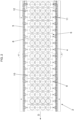
- the conveying apparatus 1 comprises a conveyor 2 developing along a closed conveying path 3.
- the conveyor 2 is configured to transport the food products in a transport direction D.
- the conveyor 2 comprises a first and second endless chain 4, 5 arranged parallel to each other.
- the two endless chains 4, 5 are so arranged like rails.
- the conveying apparatus 1 comprises a plurality of containers 6 tranversally mounted between the first and second endless chains 4, 5.
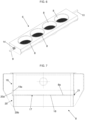
- Each container 6 comprises at least one cup-shaped receptacle 8 for the food product.
- the container 6 comprises a plurality of cup-shaped receptacles 8 arranged in a row along a direction transverse to the conveying path 3.
- each container 6 of cup-shaped receptacles 8 has an elongated extension that develops substantially in a transverse direction T between the two endless chains 4, 5.
- the transverse direction T is substantially orthogonal to the transport direction D.
- the cup-shaped receptacles 8 may have any suitable shape, depending on the food product.
- each cup-shaped receptacle 8 is arranged in a corresponding opening obtained in the container 6 and welded to it.
- each cup-shaped receptacle 8 is removably mounted in a corresponding opening obtained in the container 6.
- the cup-shaped receptacles 8 are obtained by shaping the container 6.
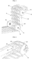
- Each container 6 comprises a first pin 9 and a second pin 10 protruding respectively from opposite ends of the container 6.
- the first pin 9 and the second pin 10 develop parallel to the transverse direction T.
- the conveyor 2 further comprises a plurality of first supports 11 and second supports 12 mounted along the two endless chains 4, 5.
- first supports 11 and the second supports 12 are arranged in pairs.
- the first support 11 and the second support 12 of a pair are located respectively on the first endless chain 4 and on the second endless chain 5, substantially opposite one another with respect to the transport direction D.
- first support 11 and the second support 12 of a pair are arranged in the inner side of the endless chains 4, 5.
- Each support 11, 12 has a bore 13 facing towards the opposite chain 4, 5. In other words, the bore 13 faces towards the container 6.
- the bore 13 faces inward.
- each container 6 is removably mounted in a pair of supports 11, 12.
- the pins 9, 10 of the container 6 are removably mounted in the bores of said supports 11, 12.
- first pin 9 and the second pin 10 of the container 6 are slidably mounted respectively in the bore 13 of the first support 11 and in the bore 13 of the second support 12.
- first pin 9 and the second pin 10 of the container 6 are also rotatably mounted respectively in the bore 13 of the first support 11 and in the bore 13 of the second support 12.
- the rotation referred to is with respect to an axial direction of the pin 9, 10, that is the transverse direction T of the container 6.
- each bore 13 is larger than the cross-section of the pins 9, 10 so that there is a tolerance gap that allows the pins 9, 10 to move within the bores 13.
- each bore 13 has an elongated development in a direction inclined both with respect to the transport direction D and to the transverse direction T.
- each bore 13 has an elongated development in a direction that is orthogonal both to the transport direction D and to the transverse direction T.
- each bore 13 has an elongated development in a direction having a vertical component.
- the bore 13 is a linear-elongated slot.
- the bore 13 has the shape of a seat for a mechanical feather key, i.e. rectangular with two rounded opposite sides.
- each bore 13 has a round shape with a diameter that is higher than the diameter of the cross-section of the pins 9, 10.
- Each bore 13 may be a through-hole or a blind hole.
- the pins 9, 10 are free to move in the bores 13. This allows to create a conveying path 3 with changes in direction and height, despite the containers 6 being mounted close to each other.
- the containers 6 are indeed kept away from the others even in changes of direction such as curves, thus avoiding collisions.
- the first pin 9 is axially slidable with respect to the container 6.
- the container 6 can be easily removed from its supports 11, 12 without the use of any tool.
- a spring 14 is provided on the first pin 9.
- the first pin 9 is axially retractable inside the container 6.
- the conveying path 3 comprises a plurality of changes of direction.
- the change of direction is a curve.
- the conveying path 3 develops over several heights.
- the curves involve a change in height.
- the conveyor 2 comprises a plurality of sprockets 15 on which the endless chains 4, 5 are mounted so as to create the curves of the conveying path 3.
- the conveying apparatus 1 comprises first guiding means 16 arranged at least one sprocket 15 and configured to engage the pins 9, 10 of a container 6 and keep them outside the pitch diameter of the sprocket 15. In this way, during the rotation of a container 6 around a sprocket 15, it is kept away from other containers and thus collision is avoided.
- the first guiding means 16 are arranged at a plurality of sprockets 15.
- the first guiding means 16 comprise two shaped profiles of a first type 22 arranged at two opposite sides of the sprocket 15. Each shaped profile of the first type 22 engages one of the pins 9,10. The shaped profile of the first type 22 is shaped so as to keep the pin 9, 10 outside the pitch diameter of the sprocket 15.
- the shaped profile of the first type 22 is a cam.
- the cam may be either fixed or rotatable with the sprocket 15.
- the conveying apparatus 1 comprises second guiding means 23 arranged at least one sprocket 15 and configured to engage the container 6 and turning it upside down.
- the second guiding means 23 comprise two shaped profiles of a second type 24 arranged at two opposite sides of the sprocket 15. Each shaped profile of the second type 24 engages a corresponding protuberance 25 on the container 6. The shaped profile of the second type 24 is shaped so as to make the container 6 turn upside down.
- the shaped profile of the second type 24 is a cam.
- the cam may be either fixed or rotatable with the sprocket 15.
- the first and second guiding means 16, 23 may be arranged at the same sprocket 15.
- each cup-shaped receptacle 8 comprises a perforated sheet 17 with a plurality of through-holes 18.
- the perforated sheet 17 is arranged to define a bottom 8a of the cup-shaped receptacle 8 for resting the food product.
- the through-holes 18 have a diameter less than or at most equal to the size of the food product so as to prevent it from falling out.
- the through-holes 18 have a diameter of between 0.5 mm and 3 mm.
- the shape of the through-holes 18 is not strictly circular. In case of non-circular shape, the diameter of the through-holes 18 mentioned above is intended to be the diameter of the inscribed circle.
- the through-holes 18 have a hexagonal shape.
- the ratio between empty and full spaces of the perforated sheet 17 is between 0.30 and 0.70. More preferably, the ratio is between 0.38 and 0.60.
- Each cup-shaped receptacle 8 comprises a lateral wall 8b and the bottom 8a previously described.
- the lateral wall 8b has a rounded and closed development, i.e. cylindrical or frustoconical.
- the lateral wall 8b is composed by a first plate 19 and a second plate 20 arranged so as to partially overlap in an overlapping zone in correspondence of the bottom 8a.
- the first plate 19 and the second plate 20 are mutually shaped in the overlapping zone so that they create an inner recess 21 for holding the bottom 8a.
- the second plate 20 in cross-section is S-shaped with a first end 20a developing outwards which, together with a free end 19a of the first plate 19, defines the inner recess 21.
- the first lateral plate 19 has a straight free end 19a.
- the S-shaped of the second plate 20 is defined by a change in curvature from the first end 20a, developing outwards and a second end 20b developing inward.
- first end 20a is superimposed out of the free end 19a of the first plate 19, while the second end 20b turns inwards, i.e. it has more internal position than the free end 19a of the first plate 19.
- the first end 20a is welded at the free end 19a of the first plate 19.
- a peripheral edge of the perforated sheet 17 is held in the inner recess 21.
- the perforated sheet 17 is mechanical interlocked to the lateral wall 8b. No welding is used for the perforated sheet 17.
- the sheet 17 is micro-perforated. Welding is not achievable on thin sheets without damaging them. Therefore, the solution described above is advised when using thin sheets, for example having thickness of 1 mm or less. Nevertheless, micro-perforation and the mounting arrangement can be used for sheets 17 with any thickness (for example, sheets with thickness of 15 mm).
- the thickness of the sheet 17 must be inferior to the diameter of the through-holes 18.
- the cup-shaped receptacles 8 have a total height that is always the same, whereas the height of the bottom 8a may be varied depending on the type of product. This is achieved by varying the length of the second end 20b of the second plate 20.
- a heat treatment apparatus 100 for food products is described below.
- the food products are noodles.
- the noodles are divided in portions or blocks.
- the portions of noodles may be of any shape, i.e. cubic, parallelepiped, spherical, conical, etc.
- the heat treatment apparatus 100 comprises a heating chamber 101.
- the heat treatment apparatus 100 comprises a conveying apparatus 1 according to any of claims 1-12.
- the upper air flow has a temperature that is comprised between 100°C and 300°C.
- the heat treatment apparatus 100 comprises a second air injecting device 103 configured to introduce into a second part 101b of the heating chamber 101 a lower air flow towards the noodles arranged in the cup-shaped receptacles 8.
- the lower air flow has a temperature that is comprised between 100°C and 300°C.
- the lower air flow is directed from the second zone 2b to the first zone 2a.
- the sliding mounting of the containers in the endless chains with their pins freely movable within the bores allows keeping the containers spaced even in changes of direction such as curves. This prevents collisions of the containers.
- the pins are free to rotate along their longitudinal axes, thus the containers can be kept with the bottoms down during the transport, preventing the product fall, but also inverted at the right time to discharge the product.
- the containers are kept as close as possible to prevent the air flow from passing in the gaps, that would lower the thermal efficiency.
- the containers are maintained at an optimized distance that is sufficient to avoid collisions and allows them to travel also in curvilinear path.
- the proposed arrangement that allows to keep the height of the cup-shaped receptacles 8 constant avoids the need of a change-over of the components acting on the containers, such as cams and guides. Further, when the conveying apparatus is used in a heat treatment apparatus where hot air is injected from below, the distance from the container and the injection point of the hot air is always the same. Furthermore, the inlet and the outlet can be kept at the same height in order to avoid air leaks.
Landscapes
- Engineering & Computer Science (AREA)
- Mechanical Engineering (AREA)
- Polymers & Plastics (AREA)
- Chemical & Material Sciences (AREA)
- Life Sciences & Earth Sciences (AREA)
- Food Science & Technology (AREA)
- Health & Medical Sciences (AREA)
- Nutrition Science (AREA)
- Commercial Cooking Devices (AREA)
- Chain Conveyers (AREA)
- Drying Of Solid Materials (AREA)
- General Preparation And Processing Of Foods (AREA)
- Noodles (AREA)
Claims (14)
- Fördervorrichtung (1) zum Fördern von Lebensmitteln, umfassend:einen Förderer (2), der sich entlang eines geschlossenen Förderwegs (3) entwickelt, wobei der Förderer (2) eine erste und eine zweite Endloskette (4, 5) umfasst, die parallel zueinander angeordnet sind,eine Vielzahl von Behältern (6), die quer zwischen der ersten und der zweiten Endloskette (4, 5) montiert sind, wobei ein jeder Behälter (6) Folgendes umfasst:- mindestens ein tassenförmiges Behältnis (8) für ein Lebensmittel;- einen ersten Zapfen (9) und einen zweiten Zapfen (10), die jeweils von entgegengesetzten Enden des Behälters (6) hervorspringen;eine Vielzahl von Paaren von Stützen (11, 12), von denen eine jede durch eine erste Stütze (11), die auf der ersten Endloskette (4) montiert ist, und eine zweite Stütze (12), die auf der zweiten Endloskette (5) montiert ist, gebildet ist,wobei eine jede Stütze (11, 12) eine Bohrung (13) aufweist, die dimensioniert und ausgeformt ist, um einen der Zapfen (9, 10) aufzunehmen, wobei der erste Zapfen (9) und der zweite Zapfen (10) eines jeden Behälters (6) entfernbar in den Bohrungen (13) von einem Paar von Stützen (11, 12) montiert sind,wobei das mindestens eine tassenförmige Behältnis (8) eine perforierte Folie (17) mit einer Vielzahl von Durchführungslöchern (18) umfasst, wobei die perforierte Folie (17) angeordnet ist, um eine Unterseite (8a) des tassenförmigen Behältnisses (8) zu definieren, um das Lebensmittel aufzulegen,dadurch gekennzeichnet, dass das mindestens eine tassenförmige Behältnis (8) eine Seitenwand (8b) umfasst, die eine erste Platte (19) und eine zweite Platte (20) umfasst, die so angeordnet sind, dass sie sich in einer Überlappungszone an der Unterseite (8a) teilweise überlappen, wobei die erste Platte (19) und die zweite Platte (20) in der Überlappungszone gegenseitig so ausgeformt sind, dass sie eine innere Ausnehmung (21) zum Halten der Unterseite (8a) schaffen.
- Fördervorrichtung (1) nach Anspruch 1, wobei der erste Zapfen (9) und der zweite Zapfen (10) eines jeden Behälters (6) verschiebbar in den Bohrungen (13) von einem Paar von Stützen (11, 12) montiert sind.
- Fördervorrichtung (1) nach Anspruch 1 oder 2, wobei der erste Zapfen (9) und der zweite Zapfen (10) eines jeden Behälters (6) axial drehbar in den Bohrungen (13) von einem Paar von Stützen (11, 12) montiert sind.
- Fördervorrichtung (1) nach einem der vorhergehenden Ansprüche, wobei die Ausdehnung einer jeden Bohrung (13) größer ist als der Querschnitt der Zapfen (9, 10).
- Fördervorrichtung (1) nach einem der vorhergehenden Ansprüche, wobei die Bohrung (13) eine langgestreckte Entwicklung in einer Richtung aufweist, die in Bezug auf eine Transportrichtung (D) des Förderers (2) geneigt ist.
- Fördervorrichtung (1) nach Anspruch 5, wobei die Bohrung (13) eine langgestreckte Entwicklung in einer Richtung aufweist, die im Wesentlichen rechtwinkelig zur Transportrichtung (D) des Förderers (2) verläuft.
- Fördervorrichtung (1) nach einem der vorhergehenden Ansprüche, wobei der erste Zapfen (9) eines jeden Behälters (6) axial in Bezug auf den entsprechenden Behälter (6) einfahrbar ist.
- Fördervorrichtung (1) nach einem der vorhergehenden Ansprüche, wobei der Förderer (2) eine Vielzahl von Ritzeln (15) umfasst, auf denen die Endlosketten (4, 5) montiert sind, und erste Führungsmittel (16), die mindestens an einem Ritzel (15) angeordnet und ausgelegt sind, um mit den Zapfen (9, 10) eines jeden Behälters (6) in Eingriff zu gelangen und diese außerhalb des Teilkreisdurchmessers des Ritzels (15) während der Drehung des Behälters (6) rund um das Ritzel (15) zu halten.
- Fördervorrichtung (1) nach Anspruch 1, wobei die Durchführungslöcher (18) einen Durchmesser zwischen 0,5 und 3 mm aufweisen.
- Fördervorrichtung (1) nach Anspruch 1 oder 9, wobei das Verhältnis zwischen leeren und vollen Bereichen der perforierten Folie (17) zwischen 0,30 und 0,70 beträgt.
- Fördervorrichtung (1) nach Anspruch 1, wobei die zweite Platte (20) im Querschnitt S-förmig ist mit einem ersten Ende (20a), das sich nach außen entwickelt, das zusammen mit einem freien Ende (19a) der ersten Platte (19) die innere Ausnehmung (21) definiert.
- Fördervorrichtung (1) nach einem der vorhergehenden Ansprüche, wobei ein jeder Behälter (6) eine Vielzahl von tassenförmigen Behältnissen (8) umfasst, die in einer Reihe entlang der Querrichtung (T) angeordnet sind, die rechtwinkelig zu einer Transportrichtung (D) des Förderers (2) verläuft.
- Wärmebehandlungsvorrichtung (100) für Lebensmittel, insbesondere Nudeln, umfassend:- eine Heizkammer (101);- eine Fördervorrichtung (1) nach einem der vorhergehenden Ansprüche,wobei der Förderer (2) der Fördervorrichtung (1) angeordnet ist, um teilweise durch die Heizkammer (101) zu führen.
- Wärmebehandlungsvorrichtung (100) nach Anspruch 13, zudem umfassend:- eine erste Luftinjektionsvorrichtung (102), die ausgelegt ist, um einen oberen Luftstrom in einen ersten Teil (101a) der Heizkammer (101) hinführend zu den Nudeln, die in den tassenförmigen Behältnissen (8) angeordnet sind, einzuführen, wobei der obere Luftstrom eine Temperatur aufweist, die zwischen 100 °C und 300 °C beträgt, und von einer ersten Zone (2a) über dem Förderer (2) zu einer zweiten Zone (2b) unter dem Förderer (2) gerichtet ist,- eine zweite Luftinjektionsvorrichtung (103), die ausgelegt ist, um einen unteren Luftstrom in einen zweiten Teil (101b) der Heizkammer (101) hinführend zu den Nudeln, die in den tassenförmigen Behältnissen (8) angeordnet sind, einzuführen, wobei der untere Luftstrom eine Temperatur aufweist, die zwischen 100 °C und 300 °C beträgt, und von der zweiten Zone (2b) zur ersten Zone (2a) gerichtet ist.
Applications Claiming Priority (2)
| Application Number | Priority Date | Filing Date | Title |
|---|---|---|---|
| IT202200000650 | 2022-01-17 | ||
| PCT/IB2022/061490 WO2023135463A1 (en) | 2022-01-17 | 2022-11-28 | Conveying apparatus for conveying food products and heat treatment apparatus |
Publications (3)
| Publication Number | Publication Date |
|---|---|
| EP4330165A1 EP4330165A1 (de) | 2024-03-06 |
| EP4330165B1 true EP4330165B1 (de) | 2025-01-15 |
| EP4330165C0 EP4330165C0 (de) | 2025-01-15 |
Family
ID=80928974
Family Applications (1)
| Application Number | Title | Priority Date | Filing Date |
|---|---|---|---|
| EP22844264.6A Active EP4330165B1 (de) | 2022-01-17 | 2022-11-28 | Fördervorrichtung zum fördern von lebensmitteln und wärmebehandlungsvorrichtung |
Country Status (9)
| Country | Link |
|---|---|
| US (1) | US12180008B2 (de) |
| EP (1) | EP4330165B1 (de) |
| JP (1) | JP2025501822A (de) |
| KR (1) | KR20240134846A (de) |
| CN (1) | CN117693479A (de) |
| ES (1) | ES3008108T3 (de) |
| MX (1) | MX2024001472A (de) |
| TW (1) | TW202330372A (de) |
| WO (1) | WO2023135463A1 (de) |
Family Cites Families (13)
| Publication number | Priority date | Publication date | Assignee | Title |
|---|---|---|---|---|
| US2664592A (en) * | 1951-09-14 | 1954-01-05 | Allied Chem & Dye Corp | Conveyer |
| US3034636A (en) * | 1960-06-20 | 1962-05-15 | Diamond National Corp | Stabilizing ring assembly |
| JPS52947Y2 (de) | 1973-06-30 | 1977-01-11 | ||
| US4166139A (en) | 1976-07-22 | 1979-08-28 | Toyo Suisan Kaisha, Ltd. | Method of producing instant cupped noodles |
| US4234612A (en) * | 1978-11-24 | 1980-11-18 | Sakuichi Sakakibara | Continuous frying method |
| JPS5618826A (en) * | 1979-07-23 | 1981-02-23 | Ohtake Noodle Mach Mfg | Frying apparatus for instant noodle |
| JPS60196160A (ja) | 1984-03-16 | 1985-10-04 | Toyo Suisan Kk | 容器入り即席めん用めん塊の連続的製造方法 |
| JPH0558426A (ja) | 1991-08-30 | 1993-03-09 | Taiyo Plast Kogyosho:Kk | バケツトコンベヤ |
| US6129939A (en) * | 1998-08-17 | 2000-10-10 | Recot, Inc. | Method for making bowl-shaped snack food products |
| US9004272B2 (en) * | 2005-12-07 | 2015-04-14 | Ackley Machine Corporation | Method and apparatus for transporting and processing a plurality of articles |
| US9828122B2 (en) * | 2012-03-15 | 2017-11-28 | Nissin Foods Holdings Co., Ltd. | Container filling apparatus |
| WO2017154572A1 (ja) * | 2016-03-09 | 2017-09-14 | 日清食品ホールディングス株式会社 | 即席フライ麺の製造方法及び製造装置 |
| JP6800547B2 (ja) | 2018-12-17 | 2020-12-16 | 日清食品ホールディングス株式会社 | フライ時間短縮方法 |
-
2022
- 2022-11-28 WO PCT/IB2022/061490 patent/WO2023135463A1/en not_active Ceased
- 2022-11-28 KR KR1020247003422A patent/KR20240134846A/ko active Pending
- 2022-11-28 ES ES22844264T patent/ES3008108T3/es active Active
- 2022-11-28 US US18/696,017 patent/US12180008B2/en active Active
- 2022-11-28 MX MX2024001472A patent/MX2024001472A/es unknown
- 2022-11-28 EP EP22844264.6A patent/EP4330165B1/de active Active
- 2022-11-28 CN CN202280051737.9A patent/CN117693479A/zh active Pending
- 2022-11-28 JP JP2023579047A patent/JP2025501822A/ja active Pending
-
2023
- 2023-01-16 TW TW112101814A patent/TW202330372A/zh unknown
Also Published As
| Publication number | Publication date |
|---|---|
| EP4330165A1 (de) | 2024-03-06 |
| CN117693479A (zh) | 2024-03-12 |
| US20240262630A1 (en) | 2024-08-08 |
| US12180008B2 (en) | 2024-12-31 |
| TW202330372A (zh) | 2023-08-01 |
| ES3008108T3 (en) | 2025-03-21 |
| WO2023135463A1 (en) | 2023-07-20 |
| MX2024001472A (es) | 2024-02-27 |
| EP4330165C0 (de) | 2025-01-15 |
| KR20240134846A (ko) | 2024-09-10 |
| JP2025501822A (ja) | 2025-01-24 |
Similar Documents
| Publication | Publication Date | Title |
|---|---|---|
| AU669408B2 (en) | Conveyor belt for treatment of particulate solid material | |
| US3938651A (en) | Self-supporting spiral conveyor | |
| US6630190B2 (en) | Tostada forming and cooking | |
| EP4330165B1 (de) | Fördervorrichtung zum fördern von lebensmitteln und wärmebehandlungsvorrichtung | |
| EP0960863B1 (de) | Ofen zur kontinuierlichen Wärmebehandlung von Glascontainern | |
| MX2007001820A (es) | Freidora de forma individual con elementos para centrar productos. | |
| JP3123226U (ja) | コンベヤーベルト用封じ込め側壁システム | |
| JP2008544935A (ja) | 細長い食品を運搬するための装置および方法 | |
| AU776734B2 (en) | Product transport system | |
| JP3952151B2 (ja) | 小物品用落下シュート | |
| US5415270A (en) | Transporting device for mass articles | |
| US11505409B2 (en) | Two-axis modular belt and conveyor | |
| US5199346A (en) | Apparatus for high speed sterilization of irregularly shaped containers | |
| US4154331A (en) | Container indexing method and apparatus | |
| US3662870A (en) | Container re-orienting mechanism | |
| EP2086334B1 (de) | Dynamische fördervorrichtung | |
| EP1726210B1 (de) | Vorrichtung zur Herstellung von aus gekochten Teigsträngen geformten gefrorenen Nestern. | |
| JPWO2023135463A5 (de) | ||
| CN108698721B (zh) | 用于容器消毒设备的运输组 | |
| DE102016121574A1 (de) | Vorrichtung zum Einschweißen | |
| JP2008113596A (ja) | 両面焼き器の反転装置及び両面焼き器 | |
| GB2065584A (en) | Supporting elements for articles to be carried by a conveyor | |
| EP0839106A1 (de) | Universeller löffel zum befüllen von behältern mit produkten aus teig | |
| EP3924261A1 (de) | Falzanordnung für eine verpackungsherstellungsmaschine | |
| JPS5813422Y2 (ja) | 自動販売機の物品搬送装置 |
Legal Events
| Date | Code | Title | Description |
|---|---|---|---|
| STAA | Information on the status of an ep patent application or granted ep patent |
Free format text: STATUS: UNKNOWN |
|
| STAA | Information on the status of an ep patent application or granted ep patent |
Free format text: STATUS: THE INTERNATIONAL PUBLICATION HAS BEEN MADE |
|
| PUAI | Public reference made under article 153(3) epc to a published international application that has entered the european phase |
Free format text: ORIGINAL CODE: 0009012 |
|
| STAA | Information on the status of an ep patent application or granted ep patent |
Free format text: STATUS: REQUEST FOR EXAMINATION WAS MADE |
|
| 17P | Request for examination filed |
Effective date: 20231127 |
|
| AK | Designated contracting states |
Kind code of ref document: A1 Designated state(s): AL AT BE BG CH CY CZ DE DK EE ES FI FR GB GR HR HU IE IS IT LI LT LU LV MC ME MK MT NL NO PL PT RO RS SE SI SK SM TR |
|
| GRAP | Despatch of communication of intention to grant a patent |
Free format text: ORIGINAL CODE: EPIDOSNIGR1 |
|
| STAA | Information on the status of an ep patent application or granted ep patent |
Free format text: STATUS: GRANT OF PATENT IS INTENDED |
|
| GRAS | Grant fee paid |
Free format text: ORIGINAL CODE: EPIDOSNIGR3 |
|
| INTG | Intention to grant announced |
Effective date: 20240923 |
|
| GRAA | (expected) grant |
Free format text: ORIGINAL CODE: 0009210 |
|
| STAA | Information on the status of an ep patent application or granted ep patent |
Free format text: STATUS: THE PATENT HAS BEEN GRANTED |
|
| DAV | Request for validation of the european patent (deleted) | ||
| DAX | Request for extension of the european patent (deleted) | ||
| AK | Designated contracting states |
Kind code of ref document: B1 Designated state(s): AL AT BE BG CH CY CZ DE DK EE ES FI FR GB GR HR HU IE IS IT LI LT LU LV MC ME MK MT NL NO PL PT RO RS SE SI SK SM TR |
|
| REG | Reference to a national code |
Ref country code: CH Ref legal event code: EP Ref country code: GB Ref legal event code: FG4D |
|
| REG | Reference to a national code |
Ref country code: DE Ref legal event code: R096 Ref document number: 602022009666 Country of ref document: DE |
|
| REG | Reference to a national code |
Ref country code: IE Ref legal event code: FG4D |
|
| U01 | Request for unitary effect filed |
Effective date: 20250127 |
|
| U07 | Unitary effect registered |
Designated state(s): AT BE BG DE DK EE FI FR IT LT LU LV MT NL PT RO SE SI Effective date: 20250203 |
|
| REG | Reference to a national code |
Ref country code: ES Ref legal event code: FG2A Ref document number: 3008108 Country of ref document: ES Kind code of ref document: T3 Effective date: 20250321 |
|
| PG25 | Lapsed in a contracting state [announced via postgrant information from national office to epo] |
Ref country code: RS Free format text: LAPSE BECAUSE OF FAILURE TO SUBMIT A TRANSLATION OF THE DESCRIPTION OR TO PAY THE FEE WITHIN THE PRESCRIBED TIME-LIMIT Effective date: 20250415 |
|
| PG25 | Lapsed in a contracting state [announced via postgrant information from national office to epo] |
Ref country code: PL Free format text: LAPSE BECAUSE OF FAILURE TO SUBMIT A TRANSLATION OF THE DESCRIPTION OR TO PAY THE FEE WITHIN THE PRESCRIBED TIME-LIMIT Effective date: 20250115 |
|
| PG25 | Lapsed in a contracting state [announced via postgrant information from national office to epo] |
Ref country code: NO Free format text: LAPSE BECAUSE OF FAILURE TO SUBMIT A TRANSLATION OF THE DESCRIPTION OR TO PAY THE FEE WITHIN THE PRESCRIBED TIME-LIMIT Effective date: 20250415 Ref country code: IS Free format text: LAPSE BECAUSE OF FAILURE TO SUBMIT A TRANSLATION OF THE DESCRIPTION OR TO PAY THE FEE WITHIN THE PRESCRIBED TIME-LIMIT Effective date: 20250515 |
|
| PG25 | Lapsed in a contracting state [announced via postgrant information from national office to epo] |
Ref country code: HR Free format text: LAPSE BECAUSE OF FAILURE TO SUBMIT A TRANSLATION OF THE DESCRIPTION OR TO PAY THE FEE WITHIN THE PRESCRIBED TIME-LIMIT Effective date: 20250115 |
|
| PG25 | Lapsed in a contracting state [announced via postgrant information from national office to epo] |
Ref country code: GR Free format text: LAPSE BECAUSE OF FAILURE TO SUBMIT A TRANSLATION OF THE DESCRIPTION OR TO PAY THE FEE WITHIN THE PRESCRIBED TIME-LIMIT Effective date: 20250416 |
|
| PG25 | Lapsed in a contracting state [announced via postgrant information from national office to epo] |
Ref country code: SM Free format text: LAPSE BECAUSE OF FAILURE TO SUBMIT A TRANSLATION OF THE DESCRIPTION OR TO PAY THE FEE WITHIN THE PRESCRIBED TIME-LIMIT Effective date: 20250115 |
|
| PG25 | Lapsed in a contracting state [announced via postgrant information from national office to epo] |
Ref country code: CZ Free format text: LAPSE BECAUSE OF FAILURE TO SUBMIT A TRANSLATION OF THE DESCRIPTION OR TO PAY THE FEE WITHIN THE PRESCRIBED TIME-LIMIT Effective date: 20250115 |
|
| PG25 | Lapsed in a contracting state [announced via postgrant information from national office to epo] |
Ref country code: SK Free format text: LAPSE BECAUSE OF FAILURE TO SUBMIT A TRANSLATION OF THE DESCRIPTION OR TO PAY THE FEE WITHIN THE PRESCRIBED TIME-LIMIT Effective date: 20250115 |
|
| PLBE | No opposition filed within time limit |
Free format text: ORIGINAL CODE: 0009261 |
|
| STAA | Information on the status of an ep patent application or granted ep patent |
Free format text: STATUS: NO OPPOSITION FILED WITHIN TIME LIMIT |
|
| 26N | No opposition filed |
Effective date: 20251016 |
|
| U20 | Renewal fee for the european patent with unitary effect paid |
Year of fee payment: 4 Effective date: 20251127 |