EP4329068A1 - Ensemble plateau de batterie et module de batterie - Google Patents
Ensemble plateau de batterie et module de batterie Download PDFInfo
- Publication number
- EP4329068A1 EP4329068A1 EP22821843.4A EP22821843A EP4329068A1 EP 4329068 A1 EP4329068 A1 EP 4329068A1 EP 22821843 A EP22821843 A EP 22821843A EP 4329068 A1 EP4329068 A1 EP 4329068A1
- Authority
- EP
- European Patent Office
- Prior art keywords
- side wall
- tray
- annular
- tray assembly
- annular side
- Prior art date
- Legal status (The legal status is an assumption and is not a legal conclusion. Google has not performed a legal analysis and makes no representation as to the accuracy of the status listed.)
- Pending
Links
Images


Classifications
-
- H—ELECTRICITY
- H01—ELECTRIC ELEMENTS
- H01M—PROCESSES OR MEANS, e.g. BATTERIES, FOR THE DIRECT CONVERSION OF CHEMICAL ENERGY INTO ELECTRICAL ENERGY
- H01M50/00—Constructional details or processes of manufacture of the non-active parts of electrochemical cells other than fuel cells, e.g. hybrid cells
- H01M50/20—Mountings; Secondary casings or frames; Racks, modules or packs; Suspension devices; Shock absorbers; Transport or carrying devices; Holders
- H01M50/204—Racks, modules or packs for multiple batteries or multiple cells
- H01M50/207—Racks, modules or packs for multiple batteries or multiple cells characterised by their shape
- H01M50/213—Racks, modules or packs for multiple batteries or multiple cells characterised by their shape adapted for cells having curved cross-section, e.g. round or elliptic
-
- H—ELECTRICITY
- H01—ELECTRIC ELEMENTS
- H01M—PROCESSES OR MEANS, e.g. BATTERIES, FOR THE DIRECT CONVERSION OF CHEMICAL ENERGY INTO ELECTRICAL ENERGY
- H01M50/00—Constructional details or processes of manufacture of the non-active parts of electrochemical cells other than fuel cells, e.g. hybrid cells
- H01M50/20—Mountings; Secondary casings or frames; Racks, modules or packs; Suspension devices; Shock absorbers; Transport or carrying devices; Holders
- H01M50/218—Mountings; Secondary casings or frames; Racks, modules or packs; Suspension devices; Shock absorbers; Transport or carrying devices; Holders characterised by the material
- H01M50/22—Mountings; Secondary casings or frames; Racks, modules or packs; Suspension devices; Shock absorbers; Transport or carrying devices; Holders characterised by the material of the casings or racks
- H01M50/227—Organic material
-
- H—ELECTRICITY
- H01—ELECTRIC ELEMENTS
- H01M—PROCESSES OR MEANS, e.g. BATTERIES, FOR THE DIRECT CONVERSION OF CHEMICAL ENERGY INTO ELECTRICAL ENERGY
- H01M50/00—Constructional details or processes of manufacture of the non-active parts of electrochemical cells other than fuel cells, e.g. hybrid cells
- H01M50/20—Mountings; Secondary casings or frames; Racks, modules or packs; Suspension devices; Shock absorbers; Transport or carrying devices; Holders
- H01M50/233—Mountings; Secondary casings or frames; Racks, modules or packs; Suspension devices; Shock absorbers; Transport or carrying devices; Holders characterised by physical properties of casings or racks, e.g. dimensions
-
- H—ELECTRICITY
- H01—ELECTRIC ELEMENTS
- H01M—PROCESSES OR MEANS, e.g. BATTERIES, FOR THE DIRECT CONVERSION OF CHEMICAL ENERGY INTO ELECTRICAL ENERGY
- H01M50/00—Constructional details or processes of manufacture of the non-active parts of electrochemical cells other than fuel cells, e.g. hybrid cells
- H01M50/20—Mountings; Secondary casings or frames; Racks, modules or packs; Suspension devices; Shock absorbers; Transport or carrying devices; Holders
- H01M50/244—Secondary casings; Racks; Suspension devices; Carrying devices; Holders characterised by their mounting method
-
- H—ELECTRICITY
- H01—ELECTRIC ELEMENTS
- H01M—PROCESSES OR MEANS, e.g. BATTERIES, FOR THE DIRECT CONVERSION OF CHEMICAL ENERGY INTO ELECTRICAL ENERGY
- H01M50/00—Constructional details or processes of manufacture of the non-active parts of electrochemical cells other than fuel cells, e.g. hybrid cells
- H01M50/20—Mountings; Secondary casings or frames; Racks, modules or packs; Suspension devices; Shock absorbers; Transport or carrying devices; Holders
- H01M50/289—Mountings; Secondary casings or frames; Racks, modules or packs; Suspension devices; Shock absorbers; Transport or carrying devices; Holders characterised by spacing elements or positioning means within frames, racks or packs
- H01M50/291—Mountings; Secondary casings or frames; Racks, modules or packs; Suspension devices; Shock absorbers; Transport or carrying devices; Holders characterised by spacing elements or positioning means within frames, racks or packs characterised by their shape
-
- H—ELECTRICITY
- H01—ELECTRIC ELEMENTS
- H01M—PROCESSES OR MEANS, e.g. BATTERIES, FOR THE DIRECT CONVERSION OF CHEMICAL ENERGY INTO ELECTRICAL ENERGY
- H01M50/00—Constructional details or processes of manufacture of the non-active parts of electrochemical cells other than fuel cells, e.g. hybrid cells
- H01M50/50—Current conducting connections for cells or batteries
- H01M50/572—Means for preventing undesired use or discharge
- H01M50/584—Means for preventing undesired use or discharge for preventing incorrect connections inside or outside the batteries
- H01M50/588—Means for preventing undesired use or discharge for preventing incorrect connections inside or outside the batteries outside the batteries, e.g. incorrect connections of terminals or busbars
-
- Y—GENERAL TAGGING OF NEW TECHNOLOGICAL DEVELOPMENTS; GENERAL TAGGING OF CROSS-SECTIONAL TECHNOLOGIES SPANNING OVER SEVERAL SECTIONS OF THE IPC; TECHNICAL SUBJECTS COVERED BY FORMER USPC CROSS-REFERENCE ART COLLECTIONS [XRACs] AND DIGESTS
- Y02—TECHNOLOGIES OR APPLICATIONS FOR MITIGATION OR ADAPTATION AGAINST CLIMATE CHANGE
- Y02E—REDUCTION OF GREENHOUSE GAS [GHG] EMISSIONS, RELATED TO ENERGY GENERATION, TRANSMISSION OR DISTRIBUTION
- Y02E60/00—Enabling technologies; Technologies with a potential or indirect contribution to GHG emissions mitigation
- Y02E60/10—Energy storage using batteries
Definitions
- the present application relates to the technical field of batteries, for example, relates to a battery tray assembly and a battery module.
- a plastic bracket or metal bracket is generally adopted as a tray structure of a battery module, of which the strength of the plastic bracket is poor, during the use of the battery module, deformation is likely to occur due to the fact that the cells are hot, so that the cells are not fixed well, and the plastic bracket is not high in fabrication size precision during fabrication, as a result, the cells are poor in assembly precision; however, when some materials with high strength and high precision are used, the cost is increased, e.g., although the metal bracket has good strength, the insulation performance of the metal bracket is poor, it is required to add insulation films or spray insulation layers, so that the fabrication process is cumbersome and the cost is high.
- the present application provides a battery tray assembly and a battery module, wherein the battery tray assembly has high mechanical strength and good insulation performance, and cells can be accurately positioned and are high in assembly precision.
- the embodiments of the present application provide a battery tray assembly, configured to fix a plurality of cells, and including:
- the battery tray assembly includes structural adhesive, wherein the structural adhesive fixedly connects the plastic bracket, the tray and the cells.
- the limiting protrusion is of a trapezoidal structure, and a V-shaped groove is formed on the side end face of the limiting protrusion which does not fit the cell.
- the side of the fixing ring facing the tray extends outwards to be provided with a first annular side wall and a second annular side wall, the first annular side wall is connected with the outer ring of the fixing ring, the second annular side wall is connected with the inner ring of the fixing ring, an annular adhesive storage groove is formed between the first annular side wall and the fixing ring, and an annular adhesive storage groove is formed between the second annular side wall and the fixing ring.
- the diameter of the avoidance hole is larger than the diameter of the inner ring of the fixing ring
- the diameter of the avoidance hole is smaller than the diameter of the outer ring of the fixing ring
- the height of the first annular side wall is smaller than the height of the second annular side wall
- the end of the first annular side wall abuts against the upper end face of the tray
- the end of the second annular side wall passes through the avoidance hole
- the end of the second annular side wall is bent to form an annular flange
- the annular flange abuts against the lower end face of the tray.
- the first annular side wall is provided with an adhesive inlet, the adhesive inlet is located at the end of the first annular side wall, and the adhesive inlet communicates with the annular adhesive storage groove.
- the lower end face of the tray is provided with a reinforcing rib, and the reinforcing rib is arranged around the avoidance holes.
- the tray includes a bottom plate and side plates which are connected with each other, and the avoidance holes are formed in the bottom plate.
- the upper end of the side plate extends outwards to form a flange, and the upper end face of the flange is provided with a hanging part.
- the outer wall of the side plate is convexly provided with a limiting block.
- the embodiments of the present application provide a battery module, which includes a plurality of cells and the battery tray assembly in any of the above solutions, wherein the plurality of cells are fixed in the battery tray assembly.
- orientation or positional relationships indicated by terms such as “central”, “upper”, “lower”, “left”, “right”, “vertical”, “horizontal”, “inner” and “outer” are the orientation or positional relationships based on the accompanying drawings, are merely intended to facilitate description of the present application and simplifying of the description, rather than to indicate or imply that the device or element referred to must have a specific orientation or be constructed and operated in a specific orientation.
- first and second are only used for descriptive purposes, and cannot be understood as indicating or implying relative importance.
- first position and “second position” are two different positions.
- first feature being “on”, “above and “over” the second feature includes that the first feature is directly above and obliquely above the second feature, or only indicates that the horizontal height of the first feature is higher than that of the second feature.
- first feature being “under”, “below” and “beneath” the second feature includes that the first feature is directly below and obliquely below the second feature, or only indicates that the horizontal height of the first features is smaller than that of the second feature.
- connection may be fixed connection or detachable connection or integrated connection, may be mechanical connection or electric connection, and may be direct connection or indirect connection through an intermediate medium, or internal communication of two elements.
- connection may be fixed connection or detachable connection or integrated connection, may be mechanical connection or electric connection, and may be direct connection or indirect connection through an intermediate medium, or internal communication of two elements.
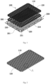
- this embodiment provides a battery tray assembly, which includes a plastic bracket 100 and a tray 200.
- the plastic bracket 100 is installed in the tray 200, and the plastic bracket 100, the tray 200 and cells are fixedly connected by structural adhesive 300.
- the plastic bracket 100 includes a frame 110 and a plurality of fixing rings 120 which are connected with each other.
- the fixing rings 120 are arrayed in a first direction and a second direction. It should be noted that in this embodiment, the first direction is the length direction of the frame 110, and the second direction is the width direction of the frame 110.
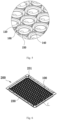
- Adjacent fixing rings 120 are connected with each other, the joint between adjacent fixing rings 120 is provided with a limiting protrusion 130 which includes a cambered surface 1301, the cambered surface 1301 fits the outer side wall of the cell, and the bottom of the cell is connected with the upper end face of the fixing ring 120.
- Each limiting protrusion 130 includes two cambered surfaces 1301, the two cambered surfaces 1301 are oppositely arranged, and the two cambered surfaces 1301 respectively fit the side walls of two adjacent cells.
- two adjacent rows of fixing rings 120 arranged in the first direction are staggered, so that three adjacent fixing rings 120 define a triangular structure; each fixing ring 120 is connected with six adjacent fixing rings 120, six limiting protrusions 130 are arranged at the joints between the fixing ring 120 and the six adjacent fixing rings 120, and the six limiting protrusions 130 and the fixing ring 120 jointly position one cell.
- the limiting protrusions 130 can clamp the side wall of the cell, and the bottom of the cell abuts against the upper end face of the fixing ring 120, so that the limiting protrusions 130 and the fixing ring 120 can position the cell and fix the cell in advance, thus ensuring the accurate installation of the cell, and facilitating the automatic placement of the cell.
- the frame 110 and the fixing rings 120 may be integrally injection-molded.
- the frame 110 and the fixing ring 120 are made of plastic materials or other materials with good insulation performance
- the tray 200 is made of a metal material. Since the bottom of the cell abuts against the fixing ring 120, the cell will not be in direct contact with the tray 200, the insulation performance is good, short circuit is avoided and the safety performance is high.
- the bottom of the cell is provided with a pressure relief structure
- the tray 200 is provided with a through avoidance hole 201 corresponding to the fixing ring 120, the fixing ring 120 and the avoidance hole 201 at the bottom of the tray 200 can avoid the pressure relief structure, when the pressure inside the cell is too high, the pressure relief structure can be forced open and flow out of the battery module through the fixing ring 120 and the avoidance hole 201, thus avoiding explosion and ensuring the safety of users.
- the tray 200 may be made of a stainless steel material, so that it is ensured that the tray 200 has high mechanical strength, thus can provide good support for the plastic bracket 100, and deformation is less likely to occur.
- the tray 200 may be integrally injection-molded from an aluminum material, on the one hand, the inj ection-molded tray 200 has high manufacturing accuracy, and the positioning of the avoidance holes 201 in the tray 200 is accurate; and on the other hand, the aluminum material also has high mechanical strength, thus can provide good support for the plastic bracket 100.
- the plastic bracket 100, the tray 200 and the cells in this embodiment may be fixedly connected by the structural adhesive 300.
- the plastic bracket 100 is installed in the tray 200, the fixing rings 120 are arranged corresponding to the avoidance holes 201, then, the structural adhesive 300 is filled into the tray 200, so that the structural adhesive 300 can flow into the triangular structure defined by three adjacent fixing rings 120 to fix three adjacent cells. Since all triangular structures are filled with the structural adhesive 300, the structural adhesive 300 can fix all the cells and the plastic tray, the triangular structure is beneficial to shortening the bonding path of the structural adhesive 300 and increases the fixing strength of the cells. The structural adhesive 300 will also flow into the gap between the plastic bracket 100 and the tray 200, thus fixedly connecting the plastic bracket 100 with the tray 200.
- the limiting protrusion 130 is of a trapezoidal structure, and a V-shaped groove 1302 is formed on the side end face of the limiting protrusion 130 that does not fit the cell.
- the bonding area of the top of the limiting protrusion 130 can be increased under the condition that the limiting size of the bottom of the limiting protrusion 130 is unchanged, so that the strength of cell grouping can be improved, and the fixing effect is good; moreover, the limiting protrusion 130 which is of the trapezoidal structure is easier to demold in the demolding process of injection molding, and the product has a good appearance.
- the arrangement of the V-shaped groove 1302 prolongs the longest flowing path of the structural adhesive 300, ensures that the structural adhesive 300 can completely fill the gaps between cells, increases the bonding area between the structural adhesive 300 and the limiting protrusion 130, and improves the fixing strength; on the other hand, the arrangement of the V-shaped groove 1302 prolongs the length of the side wall surface of the limiting protrusion 130 in the thickness direction, that is, the lengths of sides at the vertex angle of the triangular structure defined by three fixing rings 120, and the creepage distance between two cells fixed by two adjacent fixing rings 120 is the widths of the two fixing rings 120 in the radial direction plus the lengths of sides at the vertex angle of the triangular structure, thus increasing the creepage distance between two adjacent cells and ensuring the electrical safety.
- the arrangement of the V-shaped groove 1302 can also increase the creepage distance between the cell fixed by the fixing ring 120 and the tray 200 in the height direction of the limiting protrusion 130, thus ensuring the electrical safety between the cell and the
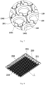
- the side of the fixing ring 120 facing the tray 200 extends outwards to be provided with a first annular side wall 140 and a second annular side wall 150.
- the first annular side wall 140 is connected with the outer ring of the fixing ring 120
- the second annular side wall 150 is connected with the inner ring of the fixing ring 120.
- An annular adhesive storage groove 160 is formed between the first annular side wall 140 and the fixing ring 120
- an annular adhesive storage groove 160 is formed between the second annular side wall 150 and the fixing ring 120
- the structural adhesive 300 can penetrate into the annular adhesive storage groove 160 so as to fixedly connect the plastic bracket 100 with the tray 200.
- the diameter of the avoidance hole 201 is larger than the diameter of the inner ring of the fixing ring 120, the diameter of the avoidance hole 201 is smaller than the diameter of the outer ring of the fixing ring 120, and the height of the first annular side wall 140 is smaller than the height of the second annular side wall 150.
- the end of the second annular side wall 150 may be bent by hot riveting, the end of the second annular side wall 150 is bent to form an annular flange, and the annular flange can wrap the avoidance hole 201 of the tray 200 and abuts against the lower end surface of the tray 200.
- the first annular side wall 140 is provided with an adhesive inlet 1401, the adhesive inlet 1401 is located at the end of the first annular side wall 140, and the adhesive inlet 1401 communicates with the annular adhesive storage groove 160, thus the structural adhesive 300 can conveniently enter the annular adhesive storage groove 160.
- a plurality of adhesive inlets 1401 may be provided, and are evenly distributed in the circumferential direction of the first annular side wall 140, and the adhesive inlets 1401 may be arranged at the triangular structure defined by three adjacent fixing rings 120, and located in the sides of the triangular structure, so that the structural adhesive 300 can fill the gap between the tray 200 and the plastic bracket 100, and the overall strength of the battery tray assembly can be improved.
- the tray 200 includes a bottom plate 210 and side plates 220 which are connected with each other.
- the avoidance holes 201 are formed in the bottom plate 210, and the bottom plate 210 and the side plates 220 together define an accommodating chamber.
- the plastic bracket 100 is installed in the accommodating chamber, the upper end of the side plate 220 extends outwards to form a flange 230, and the upper end face of the flange 230 is provided with a hanging part 231.
- the hanging part 231 may be set as a threaded hole for hoisting, so as to facilitate the transportation or assembly process of the battery tray assembly.
- the lower end face of the tray 200 is provided with a reinforcing rib 240, the reinforcing rib 240 is arranged around the avoidance holes 201, and the reinforcing rib 240 can avoid the annular flange formed at the end of the second annular side wall 150, so as to avoid interference with the annular flange that results in poor fixing effect.
- the reinforcing rib 240 may be wave-shaped. By providing the wave-shaped reinforcing rib 240, the mechanical strength of the tray 200 can be strengthened, and at the same time, the heat transfer area can be increased. When thermal runaway of the cells occurs, the reinforcing rib 240 can absorb more heat of the high-temperature gas ejected from the cells and guide out the heat generated by the high-temperature gas.
- the reinforcing rib 240 and the tray 200 may be integrally injection-molded, so that steps for processing the tray 200 are reduced, the manufacturing process is simple, and the connection strength between the reinforcing rib 240 and the tray 200 is high.
- the outer wall of the side plate 220 of the tray 200 is convexly provided with a limiting block 221.
- the battery tray assembly is convenient to position, thus ensuring the high assembly accuracy of the battery tray assembly.
- the present application also provides a battery module, which includes a plurality of cells and the above-mentioned battery tray assembly, the plurality of cells are fixed in the battery tray assembly, and the battery tray assembly has high strength, so that deformation caused by the fact that the cells are hot can be avoided; moreover, the battery tray assembly has good insulation performance, and is not easy to short-circuit, and the cells can be accurately positioned during assembly and are high in assembly precision.
Landscapes
- Chemical & Material Sciences (AREA)
- Chemical Kinetics & Catalysis (AREA)
- Electrochemistry (AREA)
- General Chemical & Material Sciences (AREA)
- Battery Mounting, Suspending (AREA)
Applications Claiming Priority (3)
| Application Number | Priority Date | Filing Date | Title |
|---|---|---|---|
| CN202221526061.8U CN217788696U (zh) | 2022-06-17 | 2022-06-17 | 一种电池的托盘组件及电池模组 |
| CN202210691720.1A CN114976459A (zh) | 2022-06-17 | 2022-06-17 | 一种电池的托盘组件及电池模组 |
| PCT/CN2022/127670 WO2023240882A1 (fr) | 2022-06-17 | 2022-10-26 | Ensemble plateau de batterie et module de batterie |
Publications (2)
| Publication Number | Publication Date |
|---|---|
| EP4329068A1 true EP4329068A1 (fr) | 2024-02-28 |
| EP4329068A4 EP4329068A4 (fr) | 2025-03-19 |
Family
ID=89193099
Family Applications (1)
| Application Number | Title | Priority Date | Filing Date |
|---|---|---|---|
| EP22821843.4A Pending EP4329068A4 (fr) | 2022-06-17 | 2022-10-26 | Ensemble plateau de batterie et module de batterie |
Country Status (2)
| Country | Link |
|---|---|
| EP (1) | EP4329068A4 (fr) |
| WO (1) | WO2023240882A1 (fr) |
Families Citing this family (1)
| Publication number | Priority date | Publication date | Assignee | Title |
|---|---|---|---|---|
| CN117747907B (zh) * | 2024-02-20 | 2024-06-21 | 江苏烽禾升智能科技有限公司 | 一种电池模组顶升定位生产线及电池模组加工方法 |
Family Cites Families (10)
| Publication number | Priority date | Publication date | Assignee | Title |
|---|---|---|---|---|
| CN102760854A (zh) * | 2012-07-13 | 2012-10-31 | 八叶(厦门)新能源科技有限公司 | 蓄电池组 |
| TWM460416U (zh) * | 2013-05-17 | 2013-08-21 | Phoenix Silicon Int Corp | 電芯固定架及其動力電池組 |
| WO2017081838A1 (fr) * | 2015-11-12 | 2017-05-18 | パナソニックIpマネジメント株式会社 | Bloc batterie |
| CN107195827A (zh) * | 2017-06-30 | 2017-09-22 | 苏州安靠电源有限公司 | 电池模组和大容量电池 |
| KR102223809B1 (ko) * | 2017-11-09 | 2021-03-04 | 주식회사 엘지화학 | 2차 전지 셀 모듈 및 그 조립 방법 |
| CN109346632B (zh) * | 2018-09-21 | 2021-04-06 | 浙江零跑科技有限公司 | 浸入式涂胶支架及组装方法 |
| CN208873794U (zh) * | 2018-09-21 | 2019-05-17 | 浙江零跑科技有限公司 | 一种浸入式涂胶支架 |
| CN113394483A (zh) * | 2021-07-15 | 2021-09-14 | 湖北亿纬动力有限公司 | 一种电池包、动力电池系统及电动车辆 |
| CN114006107B (zh) * | 2021-11-29 | 2024-09-24 | 多氟多新能源科技有限公司 | 一种圆柱电池模组及使用该模组的电池包 |
| CN114976459A (zh) * | 2022-06-17 | 2022-08-30 | 湖北亿纬动力有限公司 | 一种电池的托盘组件及电池模组 |
-
2022
- 2022-10-26 EP EP22821843.4A patent/EP4329068A4/fr active Pending
- 2022-10-26 WO PCT/CN2022/127670 patent/WO2023240882A1/fr not_active Ceased
Also Published As
| Publication number | Publication date |
|---|---|
| EP4329068A4 (fr) | 2025-03-19 |
| WO2023240882A1 (fr) | 2023-12-21 |
Similar Documents
| Publication | Publication Date | Title |
|---|---|---|
| US20230411753A1 (en) | Battery tray assembly and battery module | |
| US11894510B2 (en) | Battery pack and vehicle | |
| US20240222779A1 (en) | Cell module and battery system | |
| KR102938528B1 (ko) | 배터리 및 전자제품 | |
| EP4542747A1 (fr) | Bloc-batterie | |
| CN217788692U (zh) | 一种电池包 | |
| EP4354633A1 (fr) | Ensemble ccs, structure de module de batterie et batterie | |
| CN114976459A (zh) | 一种电池的托盘组件及电池模组 | |
| EP3460868B1 (fr) | Module de batterie | |
| CN116830332A (zh) | 电池组及其制造方法 | |
| CN220041959U (zh) | 电池侧板及电池 | |
| WO2024017130A1 (fr) | Plaque de support inférieure, élément de batterie, bloc-batterie et dispositif électrique | |
| EP4465413A1 (fr) | Module de batterie et bloc-batterie | |
| CN221239679U (zh) | 一种电池包 | |
| EP4704235A1 (fr) | Structure de groupement d'éléments de batterie et batterie ctp | |
| US20240120591A1 (en) | Battery cell module and battery system | |
| CN217788696U (zh) | 一种电池的托盘组件及电池模组 | |
| WO2023240882A1 (fr) | Ensemble plateau de batterie et module de batterie | |
| CN116799447A (zh) | 下塑胶、端盖组件、储能装置和用电设备 | |
| US20250167356A1 (en) | Top cover assembly and battery | |
| CN221009051U (zh) | 壳体和具有其的电池单体 | |
| JP7527490B2 (ja) | 電池及び電池モジュール | |
| CN216928752U (zh) | 一种集成冷却系统的电池箱体及电池包 | |
| CN116706356A (zh) | 电池防转顶盖和动力电池 | |
| CN118763348B (zh) | 电池模组和电池 |
Legal Events
| Date | Code | Title | Description |
|---|---|---|---|
| STAA | Information on the status of an ep patent application or granted ep patent |
Free format text: STATUS: UNKNOWN |
|
| STAA | Information on the status of an ep patent application or granted ep patent |
Free format text: STATUS: THE INTERNATIONAL PUBLICATION HAS BEEN MADE |
|
| PUAI | Public reference made under article 153(3) epc to a published international application that has entered the european phase |
Free format text: ORIGINAL CODE: 0009012 |
|
| STAA | Information on the status of an ep patent application or granted ep patent |
Free format text: STATUS: REQUEST FOR EXAMINATION WAS MADE |
|
| 17P | Request for examination filed |
Effective date: 20221220 |
|
| AK | Designated contracting states |
Kind code of ref document: A1 Designated state(s): AL AT BE BG CH CY CZ DE DK EE ES FI FR GB GR HR HU IE IS IT LI LT LU LV MC ME MK MT NL NO PL PT RO RS SE SI SK SM TR |
|
| A4 | Supplementary search report drawn up and despatched |
Effective date: 20250218 |
|
| RIC1 | Information provided on ipc code assigned before grant |
Ipc: H01M 50/264 20210101ALI20250212BHEP Ipc: H01M 50/227 20210101ALI20250212BHEP Ipc: H01M 50/213 20210101ALI20250212BHEP Ipc: H01M 50/204 20210101ALI20250212BHEP Ipc: H01M 50/291 20210101AFI20250212BHEP |
|
| DAV | Request for validation of the european patent (deleted) | ||
| DAX | Request for extension of the european patent (deleted) |