EP4328518B1 - Abdeckvorrichtung - Google Patents
Abdeckvorrichtung Download PDFInfo
- Publication number
- EP4328518B1 EP4328518B1 EP23181227.2A EP23181227A EP4328518B1 EP 4328518 B1 EP4328518 B1 EP 4328518B1 EP 23181227 A EP23181227 A EP 23181227A EP 4328518 B1 EP4328518 B1 EP 4328518B1
- Authority
- EP
- European Patent Office
- Prior art keywords
- metal plate
- protection device
- roof
- covering device
- covering
- Prior art date
- Legal status (The legal status is an assumption and is not a legal conclusion. Google has not performed a legal analysis and makes no representation as to the accuracy of the status listed.)
- Active
Links
Images

Classifications
-
- F—MECHANICAL ENGINEERING; LIGHTING; HEATING; WEAPONS; BLASTING
- F24—HEATING; RANGES; VENTILATING
- F24S—SOLAR HEAT COLLECTORS; SOLAR HEAT SYSTEMS
- F24S25/00—Arrangement of stationary mountings or supports for solar heat collector modules
- F24S25/40—Arrangement of stationary mountings or supports for solar heat collector modules using plate-like mounting elements, e.g. profiled or corrugated plates; Plate-like module frames
-
- E—FIXED CONSTRUCTIONS
- E04—BUILDING
- E04D—ROOF COVERINGS; SKY-LIGHTS; GUTTERS; ROOF-WORKING TOOLS
- E04D13/00—Special arrangements or devices in connection with roof coverings; Protection against birds; Roof drainage ; Sky-lights
- E04D13/12—Devices or arrangements allowing walking on the roof or in the gutter
-
- E—FIXED CONSTRUCTIONS
- E04—BUILDING
- E04D—ROOF COVERINGS; SKY-LIGHTS; GUTTERS; ROOF-WORKING TOOLS
- E04D3/00—Roof covering by making use of flat or curved slabs or stiff sheets
- E04D3/24—Roof covering by making use of flat or curved slabs or stiff sheets with special cross-section, e.g. with corrugations on both sides, with ribs, flanges, or the like
- E04D3/30—Roof covering by making use of flat or curved slabs or stiff sheets with special cross-section, e.g. with corrugations on both sides, with ribs, flanges, or the like of metal
-
- F—MECHANICAL ENGINEERING; LIGHTING; HEATING; WEAPONS; BLASTING
- F24—HEATING; RANGES; VENTILATING
- F24S—SOLAR HEAT COLLECTORS; SOLAR HEAT SYSTEMS
- F24S25/00—Arrangement of stationary mountings or supports for solar heat collector modules
- F24S25/60—Fixation means, e.g. fasteners, specially adapted for supporting solar heat collector modules
- F24S25/61—Fixation means, e.g. fasteners, specially adapted for supporting solar heat collector modules for fixing to the ground or to building structures
- F24S25/613—Fixation means, e.g. fasteners, specially adapted for supporting solar heat collector modules for fixing to the ground or to building structures in the form of bent strips or assemblies of strips; Hook-like connectors; Connectors to be mounted between building-covering elements
-
- H—ELECTRICITY
- H02—GENERATION; CONVERSION OR DISTRIBUTION OF ELECTRIC POWER
- H02S—GENERATION OF ELECTRIC POWER BY CONVERSION OF INFRARED RADIATION, VISIBLE LIGHT OR ULTRAVIOLET LIGHT, e.g. USING PHOTOVOLTAIC [PV] MODULES
- H02S20/00—Supporting structures for PV modules
- H02S20/20—Supporting structures directly fixed to an immovable object
- H02S20/22—Supporting structures directly fixed to an immovable object specially adapted for buildings
- H02S20/23—Supporting structures directly fixed to an immovable object specially adapted for buildings specially adapted for roof structures
-
- F—MECHANICAL ENGINEERING; LIGHTING; HEATING; WEAPONS; BLASTING
- F24—HEATING; RANGES; VENTILATING
- F24S—SOLAR HEAT COLLECTORS; SOLAR HEAT SYSTEMS
- F24S25/00—Arrangement of stationary mountings or supports for solar heat collector modules
- F24S2025/01—Special support components; Methods of use
- F24S2025/015—Supports with play between elements
-
- Y—GENERAL TAGGING OF NEW TECHNOLOGICAL DEVELOPMENTS; GENERAL TAGGING OF CROSS-SECTIONAL TECHNOLOGIES SPANNING OVER SEVERAL SECTIONS OF THE IPC; TECHNICAL SUBJECTS COVERED BY FORMER USPC CROSS-REFERENCE ART COLLECTIONS [XRACs] AND DIGESTS
- Y02—TECHNOLOGIES OR APPLICATIONS FOR MITIGATION OR ADAPTATION AGAINST CLIMATE CHANGE
- Y02B—CLIMATE CHANGE MITIGATION TECHNOLOGIES RELATED TO BUILDINGS, e.g. HOUSING, HOUSE APPLIANCES OR RELATED END-USER APPLICATIONS
- Y02B10/00—Integration of renewable energy sources in buildings
- Y02B10/10—Photovoltaic [PV]
-
- Y—GENERAL TAGGING OF NEW TECHNOLOGICAL DEVELOPMENTS; GENERAL TAGGING OF CROSS-SECTIONAL TECHNOLOGIES SPANNING OVER SEVERAL SECTIONS OF THE IPC; TECHNICAL SUBJECTS COVERED BY FORMER USPC CROSS-REFERENCE ART COLLECTIONS [XRACs] AND DIGESTS
- Y02—TECHNOLOGIES OR APPLICATIONS FOR MITIGATION OR ADAPTATION AGAINST CLIMATE CHANGE
- Y02E—REDUCTION OF GREENHOUSE GAS [GHG] EMISSIONS, RELATED TO ENERGY GENERATION, TRANSMISSION OR DISTRIBUTION
- Y02E10/00—Energy generation through renewable energy sources
- Y02E10/50—Photovoltaic [PV] energy
Definitions
- the invention relates to a covering device for covering an area of a roof, preferably for attaching a solar panel or a photovoltaic module.
- Appropriate covering devices are, for example, made of DE 20 2021 100 034 U1 which describes a covering device according to the preamble of claim 1.
- the disadvantage is that the construction is comparatively complex, as a roof hook is inserted through a recess in the cover device. This means that, for example, a rubber sleeve is required to seal the recess.
- the covering device according to the invention is designed or can be used for covering an area of a roof, preferably for fastening a solar panel or a photovoltaic module.
- the roof can be a sloping roof, for example.
- a roof hook can be attached or supported to the roof in this area.
- a solar panel or photovoltaic module can then be attached to the roof hook, e.g., screwed and/or clamped.
- the covering device comprises a metal plate that is at least substantially free of openings.
- the cover device does not have a central recess for a roof hook, for example.
- no rubber sleeve or the like is necessary.
- the covering device is also universally applicable.
- the covering device can be used regardless of the type of roof tile.
- the position of the cover device on the roof is essentially arbitrary.
- the cover device can be attached anywhere on the roof covering, preferably regardless of whether there is a rafter in that area or not.
- a roof hook for example, can be supported on the cover device. However, it does not pass through the metal plate.
- the cover device is compatible with all current roof hooks.
- the metal plate may preferably be rectangular, e.g. square.
- the metal plate can have a height between 30 cm and 60 cm, preferably between 45 cm and 55 cm.
- the width can be, for example, between 40 cm and 70 cm, preferably between 50 cm and 60 cm.
- the metal plate can replace at least or exactly one, two, three, or four roof tiles.
- the dimensions are generally any size and can be adapted to specific requirements.
- the metal plate can be moved to the desired position on the roof.
- the dimensions allow for a certain amount of play to accommodate individual roof conditions, such as the position of roof battens and/or roof beams.
- the thickness of the metal plate can be, for example, between 0.1 mm and 3 mm, preferably between 0.1 mm and 1 mm, particularly preferably between 0.1 mm and 0.5 mm, e.g. 0.3 mm.
- the metal plate is therefore preferably lightweight, which makes it easier to handle.
- the metal plate may comprise or consist of an aluminum and/or lead material.
- the metal plate is a rolled aluminum sheet and/or lead sheet.
- the metal plate has a deformable, preferably bendable and/or flexible, adaptation area or adaptation section.
- the adaptation area is plate-shaped. The deformability can be ensured, for example, by the thickness of the metal plate and/or the material of the metal plate.
- the adjustment area is preferably a lower and/or upper area in the assembled state, e.g. the lower and/or upper third, quarter, fifth, sixth or seventh, of the metal plate.
- the adjustment area can be adapted to the shape of the roof tiles adjoining the cover device, preferably above and/or below.
- the adjustment area can be manually shaped and/or pressed to the contour of the roof tiles during installation.
- the adjustment area and the roof tiles overlap.
- the metal plate has a cover area or cover section, with the cover area having corrugations.
- the cover area is plate-shaped.
- the metal plate can have corrugations all over or only in sections.
- the ribbing increases the stability of the metal plate, preventing it from sagging.
- the metal plate can first be rolled.
- a ribbing can then be applied, for example, using one or more embossing rollers.
- the corrugations are preferably arranged longitudinally. This allows dirt and/or water to be drained away from top to bottom in a controlled manner. This allows water to be drained away, for example, in windy conditions.
- the wind cannot easily drive the water sideways under the roofing because windless zones are created in the valleys of the corrugations.
- the metal plate can also be used to guide cables.
- cables can be routed from the interior of the building to the roof.
- the metal plate is preferably formed as a single piece.
- the cover portion and the adapter portion can be formed as a single piece.
- the cover portion and the adapter portion are made of the same material. Therefore, no separate material is required to adapt to the shape of the roof tiles. This helps keep manufacturing costs low.
- the coverage area and the adjustment area merge into one another.
- the coverage area and the adjustment area are the same width.
- a kick protection device is arranged on the underside of the metal plate.
- the kick protection device can, for example, be directly or indirectly attached to or connected to the metal plate.
- the kick protection device can preferably be rectangular, e.g. square.
- the kick protection device prevents, for example, a fitter from breaking through the metal plate.
- the kick protection device also prevents ice and snow from penetrating under the roof skin.
- the kick protection device can optionally be used to prevent tile breakage caused by the pressure of the roof hooks.
- the kick guard can optionally be used as a support for roof hooks above it. This improves the structural stability.
- the kick protection device can therefore be multifunctional, for example.
- the kick protection device can also serve, at least primarily, solely as protection against stepping on.
- the kick protection device is attached, preferably centrally, to the underside of the metal plate.
- the kick protection device is thus firmly, preferably inseparably, connected to the metal plate.
- the kick protection device is glued to the metal plate.
- the kick protection device can thus be connected to the metal plate in a cost-effective manner.
- the kick guard can be riveted to the metal plate.
- the kick protection device is plate-shaped.
- the kick protection device is oriented parallel to the metal plate.
- the kick protection device is free of corrugations.
- the kick protection device has at least one downwardly directed projection.
- exactly or at least two, three, or four projections are provided.
- exactly or at least one projection can be provided on each side.
- the projection can be straight or hook-shaped.
- the projection can extend at right angles from the rest of the kick protection device.
- the projection allows for easy adjustment to the desired height. Different heights can be achieved, for example, by using different roof battens and/or tiles.
- the kick protection device is smaller than the metal plate.
- the surface area of the kick guard is at most 1/2, 1/3, 1/4, 1/5, or 1/6 the size of the metal plate.
- the kick guard stabilizes only a portion of the metal plate.
- the kick protection device can extend below the entire cover area.
- the kick protection device comprises or consists of a metal material.
- the kick protection device is preferably rigid and non-deformable. This allows it to withstand loads, such as the weight of a technician.
- the corrugations have or consist of wave-shaped, sawtooth-shaped, rectangular and/or trapezoidal structures.
- the corrugations are provided on the top and bottom of the metal plate.
- mountains on the top can form valleys on the bottom and vice versa.
- the roof hook When mounted, the roof hook can, for example, rest on the cover device.
- Fig. 1 shows a covering device for covering an area of a roof.
- the covering device comprises an opening-free metal plate 10 with deformable adjustment regions 12.
- the adjustment regions 12 can be provided at an upper and a lower region of the metal plate 10.
- the adjustment areas 12 can be adjusted to the contours of the roof tiles below and/or above. For example, the adjustment areas 12 can be pressed into place by hand.
- the metal plate 10 further has a cover area 14 with corrugations 16.
- the metal plate 10 can be bent on three sides.
- the end regions of the sides can form a bend 18. This prevents dirt and/or water from penetrating the roof.
- a kick protection device 20 is arranged on the underside of the metal plate 10.
- the kick protection device 20 has a downward-facing projection 22 on each of its four sides.
- the projections 22 can be used to attach it to a substructure.
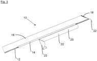
- the projections 22 are partly also visible in the side view in Fig. 3 to see.
Landscapes
- Engineering & Computer Science (AREA)
- Architecture (AREA)
- Civil Engineering (AREA)
- Structural Engineering (AREA)
- Physics & Mathematics (AREA)
- Life Sciences & Earth Sciences (AREA)
- Sustainable Development (AREA)
- Sustainable Energy (AREA)
- Thermal Sciences (AREA)
- Chemical & Material Sciences (AREA)
- Combustion & Propulsion (AREA)
- Mechanical Engineering (AREA)
- General Engineering & Computer Science (AREA)
- Roof Covering Using Slabs Or Stiff Sheets (AREA)
Description
- Die Erfindung betrifft eine Abdeckvorrichtung zum Abdecken eines Bereichs eines Dachs, vorzugsweise zur Befestigung eines Solarpanels oder eines Photovoltaikmoduls.
- Entsprechende Abdeckvorrichtungen sind beispielsweise aus
DE 20 2021 100 034 U1 bekannt, der eine Abdeckvorrichtung gemäß dem Oberbegriff des Anspruchs 1 beschreibt. - Nachteilig daran ist, dass die Konstruktion vergleichsweise komplex ist, da ein Dachhaken durch eine Aussparung der Abdeckvorrichtung geführt wird. Dies führt dazu, dass z.B. eine Gummimanschette erforderlich ist, um die Aussparung abzudichten.
- Es ist daher eine Aufgabe der Erfindung, eine Abdeckvorrichtung sowie ein System zu schaffen, welche/s auf einfache und kostengünstige Weise einen Bereich eines Dachs abdichtet.
- Die Lösung dieser Aufgabe erfolgt durch die Gegenstände der unabhängigen Ansprüche.
- Die erfindungsgemäße Abdeckvorrichtung ist zum Abdecken eines Bereichs eines Dachs, vorzugsweise zur Befestigung eines Solarpanels oder eines Photovoltaikmoduls, ausgebildet oder kann hierzu verwendet werden.
- Bei dem Dach kann es sich z.B. um ein Schrägdach handeln.
- Vorzugsweise kann in dem Bereich ein Dachhaken am Dach befestigt bzw. abgestützt werden. Am Dachhaken kann wiederum ein Solarpanel oder ein Photovoltaikmodul befestigt, z.B. verschraubt und/oder verklemmt, werden.
- Die Abdeckvorrichtung weist eine zumindest im Wesentlichen öffnungsfreie Metallplatte auf.
- Folglich weist die Abdeckvorrichtung beispielsweise keine, z.B. zentrale, Aussparung für einen Dachhaken auf. Somit ist keine Gummimanschette oder dergleichen notwendig.
- Dies ermöglicht es, einen Bereich eines Dachs auf einfache und kostengünstige Weise abzudichten. Auch ist die Abdeckvorrichtung universell einsetzbar. Beispielsweise kann die Abdeckvorrichtung unabhängig von der Art der Dachziegel eingesetzt werden.
- Die Position der Abdeckvorrichtung auf dem Dach ist grundsätzlich beliebig. So kann die Abdeckvorrichtung an einer beliebigen Stelle auf der Dachhaut befestigt werden, vorzugsweise unabhängig davon, ob sich in diesem Bereich ein Sparren befindet oder nicht.
- Ein Dachhaken kann beispielsweise auf der Abdeckvorrichtung abgestützt werden. Dieser wird jedoch nicht durch die Metallplatte hindurchgeführt.
- Dadurch, dass sich die Dachhaken auf der Abdeckvorrichtung lediglich abstützen, ist die Abdeckvorrichtung mit allen derzeitigen Dachhaken kompatibel.
- Die Metallplatte ist zumindest im Wesentlichen öffnungsfrei, also geschlossen. Beispielsweise kleinerer Löcher, z.B. Bohrlöcher oder dergleichen, zum Beispiel zum Verschrauben an einer Unterkonstruktion und/oder zur Befestigung mit der Trittschutzvorrichtung, können dabei jedoch vorgesehen sein. Diese sind im montierten Zustand vorzugsweise ebenfalls geschlossen.
- Die Metallplatte kann vorzugsweise rechteckförmig, z.B. quadratisch, ausgebildet sein.
- Beispielsweise kann die Metallplatte eine Höhe zwischen 30 cm und 60 cm, vorzugsweise zwischen 45 cm und 55 cm, aufweisen. Die Breite kann beispielsweise zwischen 40 cm und 70 cm, vorzugsweise zwischen 50 cm und 60 cm, betragen.
- Von der Abmessung kann die Metallplatte z.B. mindestens oder genau einen, zwei, drei oder vier Dachziegel ersetzen. Grundsätzlich ist die Abmessung jedoch beliebig groß und kann an die jeweiligen Erfordernisse angepasst werden.
- Beispielsweise kann die Metallplatte an die gewünschte Position auf dem Dach verschoben werden. Durch die Dimensionierung ist ein gewisses Spiel vorhanden, um den individuellen Gegebenheiten auf dem Dach, z.B. der Position von Dachlatten und/oder Dachbalken, Rechnung zu tragen.
- Die Stärke der Metallplatte kann beispielsweise zwischen 0,1 mm und 3 mm, vorzugsweise zwischen 0,1 mm und 1 mm, besonders bevorzugt zwischen 0,1 mm und 0,5 mm, z.B. 0,3 mm, betragen.
- Die Metallplatte weist somit vorzugsweise ein geringes Gewicht auf, was die Handhabung erleichtert.
- Beispielsweise kann die Metallplatte ein Aluminium- und/oder Bleimaterial umfassen oder daraus bestehen. Vorzugsweise handelt es sich bei der Metallplatte um ein gewalztes Aluminiumblech und/oder Bleiblech.
- Die Metallplatte weist einen verformbaren, also vorzugsweise biegbaren und/oder flexiblen, Anpassbereich bzw. Anpassabschnitt auf. Als Teil der Metallplatte ist der Anpassbereich plattenförmig. Die Verformbarkeit kann z.B. über die Dicke der Metallplatte und/oder das Material der Metallplatte gewährleistet werden.
- Bei dem Anpassbereich handelt es sich vorzugsweise um einen im montierten Zustand unteren und/oder oberen Bereich, z.B. das untere und/oder obere Drittel, Viertel, Fünftel, Sechstel oder Siebtel, der Metallplatte.
- Der Anpassbereich kann an die Form der sich an die Abdeckvorrichtung, vorzugsweise darunter und/oder darüber, anschließenden Dachziegel angepasst werden. Beispielsweise kann der Anpassbereich per Hand bei der Montage an die Kontur der Dachziegel angeformt und/oder angedrückt werden.
- Vorzugsweise überlappen der Anpassbereich und die Dachziegel.
- Auf diese Weise wird verhindert, dass Verschmutzungen und/oder Wasser am Übergang zwischen der Abdeckvorrichtung und den Dachziegeln eindringen. Beispielsweise Regen- und/oder Schmelzwasser können vielmehr ungehindert ablaufen.
- Die Metallplatte weist einen Abdeckbereich bzw. Abdeckabschnitt auf, wobei der Abdeckbereich Riffelungen aufweist. Als Teil der Metallplatte ist der Abdeckbereich plattenförmig.
- Die Metallplatte kann beispielsweise vollständig oder lediglich abschnittsweise Riffelungen aufweisen.
- Die Riffelungen erhöhen die Stabilität der Metallplatte. So hängt die Metallplatte beispielsweise nicht durch.
- Die Metallplatte kann z.B. zunächst gewälzt werden. Anschließend kann eine Riffelung eingebracht werden, beispielsweise mittels einer oder mehrerer Prägerolle/n.
- Vorzugsweise sind die Riffelungen in Längsrichtung angeordnet. Verschmutzungen und/oder Wasser kann somit von oben nach unten geregelt abgeführt werden. So kann beispielsweise bei Wind Wasser abgeführt werden.
- Der Wind kann das Wasser beispielsweise nicht so leicht seitlich unter die Eindeckung treiben, da in den Tälern der Riffelung windstille Zonen entstehen.
- Beispielsweise kann die Metallplatte auch dazu dienen, Leitungen zu führen. So können z.B. Leitungen vom Inneren des Gebäudes zum Dach geführt werden.
- Die Metallplatte ist vorzugsweise einstückig geformt. Beispielsweise können der Abdeckbereich und der Anpassbereich einstückig geformt sein. Vorzugsweise weisen der Abdeckbereich und der Anpassbereich dasselbe Material auf. Für die Anpassung an die Form der Dachziegel ist folglich kein separates Material notwendig. Dadurch können die Herstellungskosten geringgehalten werden.
- Vorzugsweise gehen der Abdeckbereich und der Anpassbereich ineinander über. Beispielsweise sind der Abdeckbereich und der Anpassbereich gleich breit.
- An der Unterseite der Metallplatte ist eine Trittschutzvorrichtung angeordnet. Die Trittschutzvorrichtung kann beispielsweise unmittelbar oder mittelbar an der Metallplatte befestigt bzw. mit dieser verbunden sein.
- Die Trittschutzvorrichtung kann vorzugsweise rechteckförmig, z.B. quadratisch, ausgebildet sein.
- Die Trittschutzvorrichtung stabilisiert vorzugsweise die Metallplatte, beispielsweise beim Betreten durch einen Monteur.
- Die Trittschutzvorrichtung verhindert beispielsweise, dass ein Monteur durch die Metallplatte durchbricht.
- Rein optional können durch die Trittschutzvorrichtung vorzugsweise auch Eis und Schnee nicht unter die Dachhaut eindringen.
- Zudem kann die Trittschutzvorrichtung optional dazu dienen, dass durch den Druck der Dachhaken ausgelöste Ziegelbrüche vermieden werden.
- Schließlich kann die Trittschutzvorrichtung rein optional als Abstützung für darüberliegende Dachhaken verwendet werden. Die Statik wird auf diese Weise verbessert.
- Die Trittschutzvorrichtung kann daher beispielsweise multifunktional sein. Alternativ kann die Trittschutzvorrichtung auch, zumindest hauptsächlich, lediglich als Schutz beim Betreten dienen.
- Weiterbildungen der Erfindung sind auch den abhängigen Ansprüchen, der Beschreibung sowie den beigefügten Zeichnungen zu entnehmen.
- Gemäß einer Ausführungsform ist die Trittschutzvorrichtung, vorzugsweise zentral, an der Unterseite der Metallplatte befestigt.
- Die Trittschutzvorrichtung ist somit fest, vorzugsweise unlösbar, mit der Metallplatte verbunden.
- Die Trittschutzvorrichtung kann beispielsweise in einem zentralen Bereich, einem oberen Bereich und/oder einem unteren Bereich der Metallplatte angeordnet sein.
- Nach einer weiteren Ausführungsform ist die Trittschutzvorrichtung mit der Metallplatte verklebt.
- Die Trittschutzvorrichtung kann dadurch auf kostengünstige Weise mit der Metallplatte verbunden werden.
- Alternativ kann die Trittschutzvorrichtung mit der Metallplatte vernietet sein.
- Gemäß einer weiteren Ausführungsform ist die Trittschutzvorrichtung plattenförmig ausgebildet.
- Vorzugsweise ist die Trittschutzvorrichtung parallel zur Metallplatte orientiert.
- Bevorzugt ist die Trittschutzvorrichtung frei von Riffelungen.
- Nach einer weiteren Ausführungsform weist die Trittschutzvorrichtung wenigstens einen nach unten gerichteten Vorsprung auf.
- Vorzugsweise sind genau oder mindestens zwei, drei oder vier Vorsprünge vorgesehen. Beispielsweise kann an jeder Seite genau oder wenigstens ein Vorsprung vorgesehen sein.
- Der Vorsprung kann gerade oder hakenförmig ausgebildet sein. Beispielsweise kann sich der Vorsprung rechtwinklig von der restlichen Trittschutzvorrichtung aus erstrecken.
- Durch den Vorsprung kann auf einfache Weise eine Anpassung an die gewünschte Höhe erfolgen. Unterschiedliche Höhen können sich beispielsweise durch verschiedene Dachlatten und/oder Ziegel ergeben.
- Gemäß einer weiteren Ausführungsform ist die Trittschutzvorrichtung kleiner als die Metallplatte.
- Beispielsweise ist die Fläche der Trittschutzvorrichtung höchstens 1/2, 1/3, 1/4, 1/5 oder 1/6 so groß wie die Fläche der Metallplatte. Die Trittschutzvorrichtung stabilisiert hierbei lediglich einen Abschnitt der Metallplatte.
- Alternativ kann sich die Trittschutzvorrichtung unterhalb des gesamten Abdeckbereichs erstrecken.
- Nach einer weiteren Ausführungsform weist die Trittschutzvorrichtung ein Metallmaterial auf oder besteht daraus.
- Die Trittschutzvorrichtung ist vorzugsweise nicht verformbar, also starr. Auf diese Weise hält die Trittschutzvorrichtung Belastungen, z.B. das Gewicht eines Monteurs, stand.
- Gemäß einer weiteren Ausführungsform weisen die Riffelungen wellenförmige, sägezahnförmige, rechteckförmige und/oder trapezförmige Strukturen auf oder bestehen daraus.
- Die Riffelungen sind vorzugsweise einstückig aus der Metallplatte ausgeformt. Es handelt sich beispielsweise um keine Rippen oder dergleichen, welche z.B. nachträglich mit der Metallplatte verbunden werden.
- Nach einer weiteren Ausführungsform sind die Riffelungen auf der Ober- und Unterseite der Metallplatte vorgesehen.
- So können Berge auf der Oberseite beispielsweise die Täler auf der Unterseite bilden und umgekehrt.
- Die Erfindung betrifft auch ein System mit einer erfindungsgemäßen Abdeckvorrichtung und einem Dachhaken zur Befestigung eines Solarpanels oder eines Photovoltaikmoduls.
- Im montierten Zustand kann sich der Dachhaken beispielsweise auf der Abdeckvorrichtung abstützen.
- Alle hier beschriebenen Aspekte, Ausführungsformen und Merkmale der Erfindung können, vorzugsweise auch losgelöst von der konkreten Ausgestaltung, in deren Zusammenhang sie erwähnt werden, jeweils miteinander kombiniert werden. Vorzugsweise können alle Gegenstände der abhängigen Ansprüche untereinander und mit jedem Gegenstand der unabhängigen Ansprüche kombiniert werden.
- Die Erfindung wird im Folgenden beispielhaft unter Bezugnahme auf die Zeichnungen beschrieben. Es zeigen:
- Fig. 1
- eine obere Perspektivansicht einer Ausführungsform einer erfindungsgemäßen Abdeckvorrichtung,
- Fig. 2
- eine untere Perspektivansicht einer Ausführungsform einer erfindungsgemäßen Abdeckvorrichtung, und
- Fig. 3
- eine geschnittene Seitenansicht der Ausführungsform gemäß
Fig. 2 . - Zunächst ist zu bemerken, dass die dargestellten Ausführungsformen rein beispielhafter Natur sind. So können einzelne Merkmale nicht nur in der gezeigten Kombination, sondern auch in Alleinstellung oder in anderen technisch sinnvollen Kombinationen realisiert sein. Beispielsweise können die Merkmale einer Ausführungsform beliebig mit Merkmalen einer anderen Ausführungsform kombiniert werden. Beispielsweise kann die Metallplatte auch vollständig geriffelt sein.
- Enthält eine Figur ein Bezugszeichen, welches im unmittelbar zugehörigen Beschreibungstext nicht erläutert wird, so wird auf die entsprechenden vorhergehenden bzw. nachfolgenden Ausführungen in der Figurenbeschreibung Bezug genommen. So werden für gleiche bzw. vergleichbare Bauteile in den Figuren dieselben Bezugszeichen verwendet und diese nicht nochmals erläutert.
-
Fig. 1 zeigt eine Abdeckvorrichtung zum Abdecken eines Bereichs eines Dachs. - Die Abdeckvorrichtung weist eine öffnungsfreie Metallplatte 10 mit verformbaren Anpassbereichen 12 auf. Vorzugsweise können die Anpassbereiche 12 an einem oberen und einem unteren Bereich der Metallplatte 10 vorgesehen sein.
- Der Anpassbereiche 12 können an die Kontur der darunter und/oder darüber anschließenden Dachziegel angepasst werden. Beispielsweise können die Anpassbereiche 12 per Hand angedrückt werden.
- Die Metallplatte 10 weist ferner einen Abdeckbereich 14 mit Riffelungen 16 auf.
- Vorzugsweise kann die Metallplatte 10 an drei Seiten abgekantet sein. So können die Endbereiche der Seiten einen Knick 18 bilden. Auf diese Weise wird verhindert, dass Verschmutzungen und/oder Wasser in das Dach eindringen.
- Wie in
Fig. 2 dargestellt ist, ist an der Unterseite der Metallplatte 10 eine Trittschutzvorrichtung 20 angeordnet. - Die Trittschutzvorrichtung 20 weist an allen vier Seiten jeweils einen nach unten gerichteten Vorsprung 22 auf. Über die Vorsprünge 22 kann eine Befestigung an einer Unterkonstruktion erfolgen.
- Die Vorsprünge 22 sind zum Teil auch in der Seitenansicht in
Fig. 3 zu sehen. -
- 10
- Metallplatte
- 12
- Anpassbereich
- 14
- Abdeckbereich
- 16
- Riffelung
- 18
- Knick
- 20
- Trittschutzvorrichtung
- 22
- Vorsprung
Claims (10)
- Abdeckvorrichtung zum Abdecken eines Bereichs eines Dachs, vorzugs-weise zur Befestigung eines Solarpanels oder eines Photovoltaikmoduls, aufweisendeine Metallplatte (10) mit einem verformbaren Anpassbereich (12) und mit einem Abdeckbereich (14), wobei der Abdeckbereich (14) Riffelungen (16) aufweist, undeine an der Unterseite der Metallplatte (10) angeordnete Trittschutzvorrichtung (20), dadurch gekennzeichnet, dass die Metallplatte zumindest im Wesentlichen öffnungsfrei ist.
- Abdeckvorrichtung nach Anspruch 1,
dadurch gekennzeichnet,
dass die Trittschutzvorrichtung (20), vorzugsweise zentral, an der Unterseite der Metallplatte (10) befestigt ist. - Abdeckvorrichtung nach Anspruch 1 oder 2,
dadurch gekennzeichnet,
dass die Trittschutzvorrichtung (20) mit der Metallplatte (10) verklebt ist. - Abdeckvorrichtung nach einem der vorhergehenden Ansprüche,
dadurch gekennzeichnet,
dass die Trittschutzvorrichtung (20) plattenförmig ausgebildet ist. - Abdeckvorrichtung nach einem der vorhergehenden Ansprüche,
dadurch gekennzeichnet,
dass die Trittschutzvorrichtung (20) wenigstens einen nach unten gerichteten Vorsprung (22) aufweist. - Abdeckvorrichtung nach einem der vorhergehenden Ansprüche,
dadurch gekennzeichnet,
dass die Trittschutzvorrichtung (20) kleiner als die Metallplatte (10) ist. - Abdeckvorrichtung nach einem der vorhergehenden Ansprüche,
dadurch gekennzeichnet,
dass die Trittschutzvorrichtung (20) ein Metallmaterial aufweist oder daraus besteht. - Abdeckvorrichtung nach einem der vorhergehenden Ansprüche,
dadurch gekennzeichnet,
dass die Riffelungen (16) wellenförmige, sägezahnförmige, rechteckförmige und/oder trapezförmige Strukturen aufweisen oder daraus bestehen. - Abdeckvorrichtung nach einem der vorhergehenden Ansprüche,
dadurch gekennzeichnet,
dass die Riffelungen (16) auf der Ober- und Unterseite der Metallplatte (10) vorgesehen sind. - System mit einer Abdeckvorrichtung nach einem der vorhergehenden Ansprüche und einem Dachhaken zur Befestigung eines Solarpanels oder eines Photovoltaikmoduls.
Applications Claiming Priority (1)
| Application Number | Priority Date | Filing Date | Title |
|---|---|---|---|
| DE102022121439.7A DE102022121439A1 (de) | 2022-08-24 | 2022-08-24 | Abdeckvorrichtung |
Publications (3)
| Publication Number | Publication Date |
|---|---|
| EP4328518A1 EP4328518A1 (de) | 2024-02-28 |
| EP4328518C0 EP4328518C0 (de) | 2025-04-23 |
| EP4328518B1 true EP4328518B1 (de) | 2025-04-23 |
Family
ID=89659054
Family Applications (1)
| Application Number | Title | Priority Date | Filing Date |
|---|---|---|---|
| EP23181227.2A Active EP4328518B1 (de) | 2022-08-24 | 2023-06-23 | Abdeckvorrichtung |
Country Status (3)
| Country | Link |
|---|---|
| EP (1) | EP4328518B1 (de) |
| DE (1) | DE102022121439A1 (de) |
| ES (1) | ES3030267T3 (de) |
Citations (26)
| Publication number | Priority date | Publication date | Assignee | Title |
|---|---|---|---|---|
| US3011289A (en) | 1958-06-12 | 1961-12-05 | Ceco Steel Products Corp | Corrugated building material |
| EP0180092A1 (de) | 1984-10-19 | 1986-05-07 | Oskar Fleck | Dacheindeckungsplatte |
| EP0038222B1 (de) | 1980-04-15 | 1989-03-08 | V. Kann Rasmussen Industri A/S | Verformbares Dachabdichtungsmaterial |
| DE19701105A1 (de) | 1996-01-19 | 1997-07-24 | Oskar Fleck | Dachtritteindeckungsplatte |
| DE29817410U1 (de) | 1998-09-29 | 1999-01-21 | Lück, Wilhelm, 57250 Netphen | Dachplatte aus Metall oder Kunststoff mit oder ohne Stütze bzw. Halter zum Anbringen von Dachzubehörteilen und Dachaufbauten auf geneigten Dächern |
| DE29821611U1 (de) | 1998-12-03 | 1999-02-04 | Fleck, Oskar, 45711 Datteln | Dachtritteindeckungsplatte für Schieferdächer |
| DE29818738U1 (de) | 1998-10-21 | 1999-05-20 | Fleck, Oskar, 45711 Datteln | Solareindeckungsplatte |
| DE19914071A1 (de) | 1999-03-27 | 2000-10-19 | Oskar Fleck | Plastisch verformbares Abdeckmaterial |
| DE69515857T2 (de) | 1994-04-15 | 2000-12-14 | Velux Industri A/S, Soborg | Verformbares, flächiges material für dachanschlüsse und verfahren zur herstellung eines solchen materials |
| DE69819753T2 (de) | 1997-09-05 | 2004-09-30 | Vkr Holding A/S | Dachanschlussstreifen und verfahren zur herstellung eines anschlussstreifens |
| DE102005018687B3 (de) | 2005-04-20 | 2006-11-16 | Oskar Fleck | An einem Dacheindeckungselement angebrachte Halterung zur lösbaren Befestigung eines Gegenstandes, insbesondere eines Solarmoduls |
| DE102005059487A1 (de) | 2005-12-08 | 2007-07-05 | Würth Elektronik GmbH & Co. KG | Halterungssystem für dachseitige Montage |
| DE102008012248A1 (de) | 2008-03-03 | 2009-09-10 | Oskar Fleck | Gestell zur Aufdachmontage von plattenförmigen Bauelementen |
| US7861485B1 (en) | 2007-06-26 | 2011-01-04 | Wentworth Stuart H | Method for installing a stanchion on a tile roof and system therefor |
| DE102009023181A1 (de) | 2009-05-29 | 2011-01-05 | Manfred Binder | Druckpunktverteiler bei Punktbelastung durch Dachhaken zur Befestigung von Photovoltaik- und Solaranlagen, Schneefänger und Dachleitern auf div. Dacheindeckungen |
| EP2330256A2 (de) | 2009-12-07 | 2011-06-08 | Josef Kaltner | Dachpfanne mit einem variabel positionierbaren Befestigungselement für Dachaufbauten |
| US8713858B1 (en) | 2011-12-22 | 2014-05-06 | Jason Sen Xie | Roof attachment flashing system |
| AT514315A4 (de) | 2013-07-23 | 2014-12-15 | Hausruck Dach Gmbh | Dach mit einer Photovoltaikanlage |
| EP1845319B1 (de) | 2006-02-02 | 2016-01-13 | Otto Lehmann GmbH | Befestigungsanordnung für die aufdachmontage von auf einem geneigten gebäudedach montierbaren dachzubehörelementen |
| US20170237387A1 (en) | 2016-02-12 | 2017-08-17 | Solarcity Corporation | Building integrated photovoltaic roofing assemblies and associated systems and methods |
| US20170356189A1 (en) | 2016-06-08 | 2017-12-14 | Rillito River Solar, Llc | Tile flashing |
| US10151114B2 (en) | 2010-01-25 | 2018-12-11 | Rillito River Solar, Llc | Roof mount assembly |
| US10472828B2 (en) | 2010-01-25 | 2019-11-12 | EcoFasten Solar, LLC | Roof mounting system |
| US20200228051A1 (en) | 2017-09-08 | 2020-07-16 | Unirac Inc. | Replacement Tile Mount for Mounting Solar Panels on Tile Roofs |
| DE202021100034U1 (de) | 2021-01-05 | 2021-02-01 | Sl Rack Gmbh | Abdeckvorrichtung |
| DE102021100081A1 (de) | 2021-01-05 | 2022-07-07 | Sl Rack Gmbh | Abdeckvorrichtung |
Family Cites Families (2)
| Publication number | Priority date | Publication date | Assignee | Title |
|---|---|---|---|---|
| DE202022002927U1 (de) | 2022-08-24 | 2024-01-17 | Sl Rack Gmbh | Abdeckvorrichtung |
| DE202022104792U1 (de) | 2022-08-24 | 2022-09-28 | Sl Rack Gmbh | Abdeckvorrichtung |
-
2022
- 2022-08-24 DE DE102022121439.7A patent/DE102022121439A1/de active Pending
-
2023
- 2023-06-23 ES ES23181227T patent/ES3030267T3/es active Active
- 2023-06-23 EP EP23181227.2A patent/EP4328518B1/de active Active
Patent Citations (27)
| Publication number | Priority date | Publication date | Assignee | Title |
|---|---|---|---|---|
| US3011289A (en) | 1958-06-12 | 1961-12-05 | Ceco Steel Products Corp | Corrugated building material |
| EP0038222B1 (de) | 1980-04-15 | 1989-03-08 | V. Kann Rasmussen Industri A/S | Verformbares Dachabdichtungsmaterial |
| EP0180092A1 (de) | 1984-10-19 | 1986-05-07 | Oskar Fleck | Dacheindeckungsplatte |
| DE69515857T2 (de) | 1994-04-15 | 2000-12-14 | Velux Industri A/S, Soborg | Verformbares, flächiges material für dachanschlüsse und verfahren zur herstellung eines solchen materials |
| DE19701105A1 (de) | 1996-01-19 | 1997-07-24 | Oskar Fleck | Dachtritteindeckungsplatte |
| DE69819753T2 (de) | 1997-09-05 | 2004-09-30 | Vkr Holding A/S | Dachanschlussstreifen und verfahren zur herstellung eines anschlussstreifens |
| DE29817410U1 (de) | 1998-09-29 | 1999-01-21 | Lück, Wilhelm, 57250 Netphen | Dachplatte aus Metall oder Kunststoff mit oder ohne Stütze bzw. Halter zum Anbringen von Dachzubehörteilen und Dachaufbauten auf geneigten Dächern |
| DE29818738U1 (de) | 1998-10-21 | 1999-05-20 | Fleck, Oskar, 45711 Datteln | Solareindeckungsplatte |
| DE29821611U1 (de) | 1998-12-03 | 1999-02-04 | Fleck, Oskar, 45711 Datteln | Dachtritteindeckungsplatte für Schieferdächer |
| DE19914071A1 (de) | 1999-03-27 | 2000-10-19 | Oskar Fleck | Plastisch verformbares Abdeckmaterial |
| DE102005018687B3 (de) | 2005-04-20 | 2006-11-16 | Oskar Fleck | An einem Dacheindeckungselement angebrachte Halterung zur lösbaren Befestigung eines Gegenstandes, insbesondere eines Solarmoduls |
| DE102005059487A1 (de) | 2005-12-08 | 2007-07-05 | Würth Elektronik GmbH & Co. KG | Halterungssystem für dachseitige Montage |
| EP1845319B1 (de) | 2006-02-02 | 2016-01-13 | Otto Lehmann GmbH | Befestigungsanordnung für die aufdachmontage von auf einem geneigten gebäudedach montierbaren dachzubehörelementen |
| US7861485B1 (en) | 2007-06-26 | 2011-01-04 | Wentworth Stuart H | Method for installing a stanchion on a tile roof and system therefor |
| DE102008012248A1 (de) | 2008-03-03 | 2009-09-10 | Oskar Fleck | Gestell zur Aufdachmontage von plattenförmigen Bauelementen |
| DE102009023181A1 (de) | 2009-05-29 | 2011-01-05 | Manfred Binder | Druckpunktverteiler bei Punktbelastung durch Dachhaken zur Befestigung von Photovoltaik- und Solaranlagen, Schneefänger und Dachleitern auf div. Dacheindeckungen |
| EP2330256A2 (de) | 2009-12-07 | 2011-06-08 | Josef Kaltner | Dachpfanne mit einem variabel positionierbaren Befestigungselement für Dachaufbauten |
| US10151114B2 (en) | 2010-01-25 | 2018-12-11 | Rillito River Solar, Llc | Roof mount assembly |
| US10472828B2 (en) | 2010-01-25 | 2019-11-12 | EcoFasten Solar, LLC | Roof mounting system |
| US8713858B1 (en) | 2011-12-22 | 2014-05-06 | Jason Sen Xie | Roof attachment flashing system |
| AT514315A4 (de) | 2013-07-23 | 2014-12-15 | Hausruck Dach Gmbh | Dach mit einer Photovoltaikanlage |
| US20170237387A1 (en) | 2016-02-12 | 2017-08-17 | Solarcity Corporation | Building integrated photovoltaic roofing assemblies and associated systems and methods |
| US20170356189A1 (en) | 2016-06-08 | 2017-12-14 | Rillito River Solar, Llc | Tile flashing |
| US20200228051A1 (en) | 2017-09-08 | 2020-07-16 | Unirac Inc. | Replacement Tile Mount for Mounting Solar Panels on Tile Roofs |
| US11205989B2 (en) | 2017-09-08 | 2021-12-21 | Unirac Inc. | Replacement tile mount for mounting solar panels on tile roofs |
| DE202021100034U1 (de) | 2021-01-05 | 2021-02-01 | Sl Rack Gmbh | Abdeckvorrichtung |
| DE102021100081A1 (de) | 2021-01-05 | 2022-07-07 | Sl Rack Gmbh | Abdeckvorrichtung |
Non-Patent Citations (8)
| Title |
|---|
| ANONYMOUS: "ClickFit InstallGuide v2.6 Addendum v1.1 COMBINED", ECOFASTEN, 11 October 2021 (2021-10-11), XP093360292, Retrieved from the Internet <URL:https://ecofastensolar.com/wp-content/uploads/2021/11/ClickFit_InstallGuide_v2.6_Addendum_v1.1_COMBINED.pdf> |
| ANONYMOUS: "Knockout Tile", IRONRIDGE, 1 January 2019 (2019-01-01), XP093360279, Retrieved from the Internet <URL:https://files.ironridge.com/pitched-roof-mounting/resources/brochures/IronRidge_Knockout_Tile_Installation_Manual.pdf> |
| ANONYMOUS: "Tile Hook Flashing - INSTALLATION GUIDE (V1.0)", ECOFASTEN, 19 February 2021 (2021-02-19), XP093360287 |
| D20 - ANLAGE MATRIX-FACHWISSEN |
| D26b - TileHookFlashing_Brochure (date?) |
| D26c - 301301X-EF_CutSheet_TILE HOOK FLASH AL ST |
| D26e - Convolut |
| D26f - Technical drawings of S-, W- and flat Tile Hook Flashing |
Also Published As
| Publication number | Publication date |
|---|---|
| EP4328518C0 (de) | 2025-04-23 |
| EP4328518A1 (de) | 2024-02-28 |
| ES3030267T3 (en) | 2025-06-27 |
| DE102022121439A1 (de) | 2024-02-29 |
Similar Documents
| Publication | Publication Date | Title |
|---|---|---|
| DE202022104792U1 (de) | Abdeckvorrichtung | |
| EP4023959B1 (de) | Abdeckvorrichtung | |
| DE202021100034U1 (de) | Abdeckvorrichtung | |
| EP1845319A2 (de) | Befestigungsanordnung für die Aufdach- Montage von einem auf einem geneigten Gebäudedach montierbaren Dachzubehörelementen | |
| EP2186964B1 (de) | Dacheindeckung mit mindestens zwei Metallblechen zwischen Profilen und Solaranlage auf dieser Dacheindeckung | |
| DE102009055722A1 (de) | Halterungsvorrichtung, insbesondere für solare Module auf Trapezblechen | |
| EP4328518B1 (de) | Abdeckvorrichtung | |
| DE202022002927U1 (de) | Abdeckvorrichtung | |
| EP2527763A2 (de) | Verkleidungssystem zur Verkleidung einer Gebäudeaussenfläche | |
| EP2505936A1 (de) | Befestigungsvorrichtung für ein Trägerprofil | |
| EP1717384B1 (de) | Halterung für Dachaufsatzkomponenten | |
| DE19729309A1 (de) | Vorrichtung zur Befestigung von kastenförmigen Einrichtungen | |
| DE3314855C2 (de) | Dachhaken | |
| DE202025101151U1 (de) | Dachplatte | |
| DE102015121145A1 (de) | First- oder Gratlattenanordnung | |
| EP3680414B1 (de) | Baugruppe mit einem dacheindeckelement und zwei separat ausgebildeten befestigungselementen | |
| DE202021004147U1 (de) | Abdeckvorrichtung | |
| DE102005029361B3 (de) | First- oder Gratabdeckung | |
| DE202025106582U1 (de) | Haltevorrichtung zur Verwendung bei der Befestigung mindestens eines Objekts im Bereich einer geneigten Dachfläche, sowie Anordnung mit einer derartigen Haltevorrichtung | |
| DE202025107539U1 (de) | Abdeckvorrichtung | |
| DE29724278U1 (de) | Vorrichtung zur Befestigung von kastenförmigen Einrichtungen | |
| DE102016112241A1 (de) | Vorrichtung zur Befestigung und/oder Stabilisierung einer Firstlatte | |
| DE102015104643A1 (de) | Flächiges Dacheindeckungselement und geneigte Dachoberfläche mit einem solchen Dacheindeckungselement | |
| AT515078B1 (de) | Firstentlüftungselement | |
| DE202005010024U1 (de) | First- oder Gratabdeckelement |
Legal Events
| Date | Code | Title | Description |
|---|---|---|---|
| PUAI | Public reference made under article 153(3) epc to a published international application that has entered the european phase |
Free format text: ORIGINAL CODE: 0009012 |
|
| STAA | Information on the status of an ep patent application or granted ep patent |
Free format text: STATUS: THE APPLICATION HAS BEEN PUBLISHED |
|
| AK | Designated contracting states |
Kind code of ref document: A1 Designated state(s): AL AT BE BG CH CY CZ DE DK EE ES FI FR GB GR HR HU IE IS IT LI LT LU LV MC ME MK MT NL NO PL PT RO RS SE SI SK SM TR |
|
| STAA | Information on the status of an ep patent application or granted ep patent |
Free format text: STATUS: REQUEST FOR EXAMINATION WAS MADE |
|
| 17P | Request for examination filed |
Effective date: 20240320 |
|
| RBV | Designated contracting states (corrected) |
Designated state(s): AL AT BE BG CH CY CZ DE DK EE ES FI FR GB GR HR HU IE IS IT LI LT LU LV MC ME MK MT NL NO PL PT RO RS SE SI SK SM TR |
|
| TPAC | Observations filed by third parties |
Free format text: ORIGINAL CODE: EPIDOSNTIPA |
|
| RIC1 | Information provided on ipc code assigned before grant |
Ipc: E04D 3/30 20060101ALI20240918BHEP Ipc: F24S 25/00 20180101ALI20240918BHEP Ipc: E04D 3/24 20060101ALI20240918BHEP Ipc: E04D 3/16 20060101ALI20240918BHEP Ipc: E04C 2/32 20060101ALI20240918BHEP Ipc: H02S 20/23 20140101ALI20240918BHEP Ipc: F24S 25/613 20180101ALI20240918BHEP Ipc: E04D 13/12 20060101ALI20240918BHEP Ipc: F24S 25/40 20180101AFI20240918BHEP |
|
| GRAP | Despatch of communication of intention to grant a patent |
Free format text: ORIGINAL CODE: EPIDOSNIGR1 |
|
| STAA | Information on the status of an ep patent application or granted ep patent |
Free format text: STATUS: GRANT OF PATENT IS INTENDED |
|
| INTG | Intention to grant announced |
Effective date: 20241028 |
|
| TPAC | Observations filed by third parties |
Free format text: ORIGINAL CODE: EPIDOSNTIPA |
|
| GRAS | Grant fee paid |
Free format text: ORIGINAL CODE: EPIDOSNIGR3 |
|
| GRAA | (expected) grant |
Free format text: ORIGINAL CODE: 0009210 |
|
| STAA | Information on the status of an ep patent application or granted ep patent |
Free format text: STATUS: THE PATENT HAS BEEN GRANTED |
|
| AK | Designated contracting states |
Kind code of ref document: B1 Designated state(s): AL AT BE BG CH CY CZ DE DK EE ES FI FR GB GR HR HU IE IS IT LI LT LU LV MC ME MK MT NL NO PL PT RO RS SE SI SK SM TR |
|
| REG | Reference to a national code |
Ref country code: GB Ref legal event code: FG4D Free format text: NOT ENGLISH |
|
| REG | Reference to a national code |
Ref country code: CH Ref legal event code: EP |
|
| REG | Reference to a national code |
Ref country code: IE Ref legal event code: FG4D Free format text: LANGUAGE OF EP DOCUMENT: GERMAN |
|
| U01 | Request for unitary effect filed |
Effective date: 20250423 |
|
| U07 | Unitary effect registered |
Designated state(s): AT BE BG DE DK EE FI FR IT LT LU LV MT NL PT RO SE SI Effective date: 20250429 |
|
| REG | Reference to a national code |
Ref country code: ES Ref legal event code: FG2A Ref document number: 3030267 Country of ref document: ES Kind code of ref document: T3 Effective date: 20250627 |
|
| U20 | Renewal fee for the european patent with unitary effect paid |
Year of fee payment: 3 Effective date: 20250527 |
|
| PGFP | Annual fee paid to national office [announced via postgrant information from national office to epo] |
Ref country code: IE Payment date: 20250527 Year of fee payment: 3 |
|
| PGFP | Annual fee paid to national office [announced via postgrant information from national office to epo] |
Ref country code: ES Payment date: 20250701 Year of fee payment: 3 |
|
| PG25 | Lapsed in a contracting state [announced via postgrant information from national office to epo] |
Ref country code: NO Free format text: LAPSE BECAUSE OF FAILURE TO SUBMIT A TRANSLATION OF THE DESCRIPTION OR TO PAY THE FEE WITHIN THE PRESCRIBED TIME-LIMIT Effective date: 20250723 Ref country code: GR Free format text: LAPSE BECAUSE OF FAILURE TO SUBMIT A TRANSLATION OF THE DESCRIPTION OR TO PAY THE FEE WITHIN THE PRESCRIBED TIME-LIMIT Effective date: 20250724 |
|
| PG25 | Lapsed in a contracting state [announced via postgrant information from national office to epo] |
Ref country code: PL Free format text: LAPSE BECAUSE OF FAILURE TO SUBMIT A TRANSLATION OF THE DESCRIPTION OR TO PAY THE FEE WITHIN THE PRESCRIBED TIME-LIMIT Effective date: 20250423 |
|
| PG25 | Lapsed in a contracting state [announced via postgrant information from national office to epo] |
Ref country code: HR Free format text: LAPSE BECAUSE OF FAILURE TO SUBMIT A TRANSLATION OF THE DESCRIPTION OR TO PAY THE FEE WITHIN THE PRESCRIBED TIME-LIMIT Effective date: 20250423 |
|
| PG25 | Lapsed in a contracting state [announced via postgrant information from national office to epo] |
Ref country code: RS Free format text: LAPSE BECAUSE OF FAILURE TO SUBMIT A TRANSLATION OF THE DESCRIPTION OR TO PAY THE FEE WITHIN THE PRESCRIBED TIME-LIMIT Effective date: 20250723 |
|
| PG25 | Lapsed in a contracting state [announced via postgrant information from national office to epo] |
Ref country code: IS Free format text: LAPSE BECAUSE OF FAILURE TO SUBMIT A TRANSLATION OF THE DESCRIPTION OR TO PAY THE FEE WITHIN THE PRESCRIBED TIME-LIMIT Effective date: 20250823 |
|
| PG25 | Lapsed in a contracting state [announced via postgrant information from national office to epo] |
Ref country code: SM Free format text: LAPSE BECAUSE OF FAILURE TO SUBMIT A TRANSLATION OF THE DESCRIPTION OR TO PAY THE FEE WITHIN THE PRESCRIBED TIME-LIMIT Effective date: 20250423 |
|
| PG25 | Lapsed in a contracting state [announced via postgrant information from national office to epo] |
Ref country code: CZ Free format text: LAPSE BECAUSE OF FAILURE TO SUBMIT A TRANSLATION OF THE DESCRIPTION OR TO PAY THE FEE WITHIN THE PRESCRIBED TIME-LIMIT Effective date: 20250423 |
|
| PLBI | Opposition filed |
Free format text: ORIGINAL CODE: 0009260 |
|
| PG25 | Lapsed in a contracting state [announced via postgrant information from national office to epo] |
Ref country code: SK Free format text: LAPSE BECAUSE OF FAILURE TO SUBMIT A TRANSLATION OF THE DESCRIPTION OR TO PAY THE FEE WITHIN THE PRESCRIBED TIME-LIMIT Effective date: 20250423 |
|
| REG | Reference to a national code |
Ref country code: CH Ref legal event code: L11 Free format text: ST27 STATUS EVENT CODE: U-0-0-L10-L11 (AS PROVIDED BY THE NATIONAL OFFICE) Effective date: 20260128 |
|
| PG25 | Lapsed in a contracting state [announced via postgrant information from national office to epo] |
Ref country code: MC Free format text: LAPSE BECAUSE OF FAILURE TO SUBMIT A TRANSLATION OF THE DESCRIPTION OR TO PAY THE FEE WITHIN THE PRESCRIBED TIME-LIMIT Effective date: 20250423 |
|
| PLAB | Opposition data, opponent's data or that of the opponent's representative modified |
Free format text: ORIGINAL CODE: 0009299OPPO |
|
| PLBI | Opposition filed |
Free format text: ORIGINAL CODE: 0009260 |
|
| REG | Reference to a national code |
Ref country code: CH Ref legal event code: L10 Free format text: ST27 STATUS EVENT CODE: U-0-0-L10-L00 (AS PROVIDED BY THE NATIONAL OFFICE) Effective date: 20260204 |
|
| PLAX | Notice of opposition and request to file observation + time limit sent |
Free format text: ORIGINAL CODE: EPIDOSNOBS2 |
|
| 26 | Opposition filed |
Opponent name: BARTHOLOMAEUS GMBH Effective date: 20260120 Opponent name: AEROCOMPACT EUROPE GMBH Effective date: 20260120 |
|
| 26 | Opposition filed |
Opponent name: SCHLETTER INTERNATIONAL B.V. Effective date: 20260123 |
|
| R26 | Opposition filed (corrected) |
Opponent name: BARTHOLOMAEUS GMBH Effective date: 20260120 Opponent name: AEROCOMPACT EUROPE GMBH Effective date: 20260120 |