EP4328512A1 - Refrigeration cycle apparatur and indoor unit - Google Patents
Refrigeration cycle apparatur and indoor unit Download PDFInfo
- Publication number
- EP4328512A1 EP4328512A1 EP21937899.9A EP21937899A EP4328512A1 EP 4328512 A1 EP4328512 A1 EP 4328512A1 EP 21937899 A EP21937899 A EP 21937899A EP 4328512 A1 EP4328512 A1 EP 4328512A1
- Authority
- EP
- European Patent Office
- Prior art keywords
- damper
- heat exchange
- air
- air inlet
- exchange unit
- Prior art date
- Legal status (The legal status is an assumption and is not a legal conclusion. Google has not performed a legal analysis and makes no representation as to the accuracy of the status listed.)
- Withdrawn
Links
Images


Classifications
-
- F—MECHANICAL ENGINEERING; LIGHTING; HEATING; WEAPONS; BLASTING
- F24—HEATING; RANGES; VENTILATING
- F24F—AIR-CONDITIONING; AIR-HUMIDIFICATION; VENTILATION; USE OF AIR CURRENTS FOR SCREENING
- F24F11/00—Control or safety arrangements
- F24F11/70—Control systems characterised by their outputs; Constructional details thereof
- F24F11/72—Control systems characterised by their outputs; Constructional details thereof for controlling the supply of treated air, e.g. its pressure
- F24F11/74—Control systems characterised by their outputs; Constructional details thereof for controlling the supply of treated air, e.g. its pressure for controlling air flow rate or air velocity
-
- F—MECHANICAL ENGINEERING; LIGHTING; HEATING; WEAPONS; BLASTING
- F24—HEATING; RANGES; VENTILATING
- F24F—AIR-CONDITIONING; AIR-HUMIDIFICATION; VENTILATION; USE OF AIR CURRENTS FOR SCREENING
- F24F7/00—Ventilation
- F24F7/007—Ventilation with forced flow
-
- F—MECHANICAL ENGINEERING; LIGHTING; HEATING; WEAPONS; BLASTING
- F24—HEATING; RANGES; VENTILATING
- F24F—AIR-CONDITIONING; AIR-HUMIDIFICATION; VENTILATION; USE OF AIR CURRENTS FOR SCREENING
- F24F1/00—Room units for air-conditioning, e.g. separate or self-contained units or units receiving primary air from a central station
- F24F1/0007—Indoor units, e.g. fan coil units
- F24F1/0018—Indoor units, e.g. fan coil units characterised by fans
-
- F—MECHANICAL ENGINEERING; LIGHTING; HEATING; WEAPONS; BLASTING
- F24—HEATING; RANGES; VENTILATING
- F24F—AIR-CONDITIONING; AIR-HUMIDIFICATION; VENTILATION; USE OF AIR CURRENTS FOR SCREENING
- F24F1/00—Room units for air-conditioning, e.g. separate or self-contained units or units receiving primary air from a central station
- F24F1/0007—Indoor units, e.g. fan coil units
- F24F1/0035—Indoor units, e.g. fan coil units characterised by introduction of outside air to the room
-
- F—MECHANICAL ENGINEERING; LIGHTING; HEATING; WEAPONS; BLASTING
- F24—HEATING; RANGES; VENTILATING
- F24F—AIR-CONDITIONING; AIR-HUMIDIFICATION; VENTILATION; USE OF AIR CURRENTS FOR SCREENING
- F24F1/00—Room units for air-conditioning, e.g. separate or self-contained units or units receiving primary air from a central station
- F24F1/0007—Indoor units, e.g. fan coil units
- F24F1/0059—Indoor units, e.g. fan coil units characterised by heat exchangers
-
- F—MECHANICAL ENGINEERING; LIGHTING; HEATING; WEAPONS; BLASTING
- F24—HEATING; RANGES; VENTILATING
- F24F—AIR-CONDITIONING; AIR-HUMIDIFICATION; VENTILATION; USE OF AIR CURRENTS FOR SCREENING
- F24F1/00—Room units for air-conditioning, e.g. separate or self-contained units or units receiving primary air from a central station
- F24F1/0007—Indoor units, e.g. fan coil units
- F24F1/0059—Indoor units, e.g. fan coil units characterised by heat exchangers
- F24F1/0063—Indoor units, e.g. fan coil units characterised by heat exchangers by the mounting or arrangement of the heat exchangers
-
- F—MECHANICAL ENGINEERING; LIGHTING; HEATING; WEAPONS; BLASTING
- F24—HEATING; RANGES; VENTILATING
- F24F—AIR-CONDITIONING; AIR-HUMIDIFICATION; VENTILATION; USE OF AIR CURRENTS FOR SCREENING
- F24F1/00—Room units for air-conditioning, e.g. separate or self-contained units or units receiving primary air from a central station
- F24F1/0007—Indoor units, e.g. fan coil units
- F24F1/0071—Indoor units, e.g. fan coil units with means for purifying supplied air
- F24F1/0073—Indoor units, e.g. fan coil units with means for purifying supplied air characterised by the mounting or arrangement of filters
-
- F—MECHANICAL ENGINEERING; LIGHTING; HEATING; WEAPONS; BLASTING
- F24—HEATING; RANGES; VENTILATING
- F24F—AIR-CONDITIONING; AIR-HUMIDIFICATION; VENTILATION; USE OF AIR CURRENTS FOR SCREENING
- F24F11/00—Control or safety arrangements
- F24F11/70—Control systems characterised by their outputs; Constructional details thereof
- F24F11/80—Control systems characterised by their outputs; Constructional details thereof for controlling the temperature of the supplied air
- F24F11/81—Control systems characterised by their outputs; Constructional details thereof for controlling the temperature of the supplied air by controlling the air supply to heat-exchangers or bypass channels
-
- F—MECHANICAL ENGINEERING; LIGHTING; HEATING; WEAPONS; BLASTING
- F24—HEATING; RANGES; VENTILATING
- F24F—AIR-CONDITIONING; AIR-HUMIDIFICATION; VENTILATION; USE OF AIR CURRENTS FOR SCREENING
- F24F13/00—Details common to, or for air-conditioning, air-humidification, ventilation or use of air currents for screening
- F24F13/30—Arrangement or mounting of heat-exchangers
-
- F—MECHANICAL ENGINEERING; LIGHTING; HEATING; WEAPONS; BLASTING
- F24—HEATING; RANGES; VENTILATING
- F24F—AIR-CONDITIONING; AIR-HUMIDIFICATION; VENTILATION; USE OF AIR CURRENTS FOR SCREENING
- F24F7/00—Ventilation
- F24F7/003—Ventilation in combination with air cleaning
-
- F—MECHANICAL ENGINEERING; LIGHTING; HEATING; WEAPONS; BLASTING
- F24—HEATING; RANGES; VENTILATING
- F24F—AIR-CONDITIONING; AIR-HUMIDIFICATION; VENTILATION; USE OF AIR CURRENTS FOR SCREENING
- F24F13/00—Details common to, or for air-conditioning, air-humidification, ventilation or use of air currents for screening
- F24F13/08—Air-flow control members, e.g. louvres, grilles, flaps or guide plates
- F24F13/10—Air-flow control members, e.g. louvres, grilles, flaps or guide plates movable, e.g. dampers
-
- F—MECHANICAL ENGINEERING; LIGHTING; HEATING; WEAPONS; BLASTING
- F25—REFRIGERATION OR COOLING; COMBINED HEATING AND REFRIGERATION SYSTEMS; HEAT PUMP SYSTEMS; MANUFACTURE OR STORAGE OF ICE; LIQUEFACTION SOLIDIFICATION OF GASES
- F25B—REFRIGERATION MACHINES, PLANTS OR SYSTEMS; COMBINED HEATING AND REFRIGERATION SYSTEMS; HEAT PUMP SYSTEMS
- F25B5/00—Compression machines, plants or systems, with several evaporator circuits, e.g. for varying refrigerating capacity
- F25B5/04—Compression machines, plants or systems, with several evaporator circuits, e.g. for varying refrigerating capacity arranged in series
-
- F—MECHANICAL ENGINEERING; LIGHTING; HEATING; WEAPONS; BLASTING
- F25—REFRIGERATION OR COOLING; COMBINED HEATING AND REFRIGERATION SYSTEMS; HEAT PUMP SYSTEMS; MANUFACTURE OR STORAGE OF ICE; LIQUEFACTION SOLIDIFICATION OF GASES
- F25B—REFRIGERATION MACHINES, PLANTS OR SYSTEMS; COMBINED HEATING AND REFRIGERATION SYSTEMS; HEAT PUMP SYSTEMS
- F25B6/00—Compression machines, plants or systems, with several condenser circuits
- F25B6/04—Compression machines, plants or systems, with several condenser circuits arranged in series
Definitions
- the present disclosure relates to a refrigeration cycle apparatus and an indoor unit.
- Patent Literature 1 Japanese Unexamined Patent Application Publication No. H 11 -257793
- the indoor unit is provided with a heat exchanger dedicated to ventilation. This limits the size of a heat exchanger that can be used to perform cooling and heating without providing ventilation, and thus may decrease efficiency of the refrigeration cycle apparatus.
- the present disclosure has been made to solve the problem described above. It is an object of the present disclosure to provide a refrigeration cycle apparatus that performs cooling and heating, in which it is possible to set whether to provide ventilation and it is also possible to prevent a decrease in efficiency when the refrigeration cycle apparatus does not provide ventilation.
- a refrigeration cycle apparatus includes an indoor unit provided with a first air inlet communicating with an inside of a room and a second air inlet communicating with outside of the room; a first heat exchange unit located in a first air flow passage connecting the first air inlet and an air outlet; a second heat exchange unit located in a second air flow passage connecting the second air inlet and the air outlet, the second heat exchange unit being connected to the first heat exchange unit such that the second heat exchange unit is positioned downstream of the first heat exchange unit when the refrigeration cycle apparatus performs heating operation; a first damper capable of adjusting an amount of air entering from the first air flow passage to the second air flow passage; and a second damper provided at the second air inlet and capable of adjusting an amount of air to be sucked from the second air inlet.
- the refrigeration cycle apparatus it is possible to set whether to provide ventilation. Even when not providing ventilation, the refrigeration cycle apparatus can still exhibit equal performance compared to an indoor heat exchanger installed in some refrigeration cycle apparatus. This can prevent the refrigeration cycle apparatus from decreasing its efficiency regardless of the usage conditions.
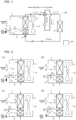
- Fig. 1 illustrates the configuration of a refrigeration cycle apparatus 100 in the present embodiment.
- the refrigeration cycle apparatus 100 includes a compressor 1, a four-way valve 2, an indoor unit 3, an expansion valve 9, and an outdoor heat exchanger 10.
- the indoor unit 3 has a first indoor heat exchange unit 4, a second indoor heat exchange unit 5, and a first indoor fan 6 accommodated in the indoor unit 3.
- the outdoor heat exchanger 10 is accommodated in an outdoor unit (not illustrated) and an outdoor fan is also accommodated in the outdoor unit.
- the refrigeration cycle apparatus 100 includes a controller 50.
- the controller 50 issues a command to the compressor 1, the four-way valve 2, the first air-sending means 6, the expansion valve 9, a first damper 11, and a second damper 12, which will be described later, and the outdoor fan (not illustrated), to control operation of the respective components.
- the compressor 1, the four-way valve 2, the first indoor heat exchange unit 4, the second indoor heat exchange unit 5, the expansion valve 9, and the outdoor heat exchanger 10 are connected by pipes, forming a refrigerant circuit.
- refrigerant such as R32 (difluoromethane) circulates.
- R32 difluoromethane
- the type of refrigerant to be filled in the refrigeration cycle apparatus 100 is not particularly limited.
- refrigerant flows in the direction shown by the dotted arrows. That is, refrigerant discharged from the compressor 1 condenses in the outdoor heat exchanger 10, is reduced in pressure by the expansion valve 9, and evaporates in the second indoor heat exchange unit 5 and the first indoor heat exchange unit 4. The refrigerant having evaporated flows back to the compressor 1.
- refrigerant flows in the direction shown by the solid arrows. That is, refrigerant discharged from the compressor 1 condenses in the first indoor heat exchange unit 4 and the second indoor heat exchange unit 5, is reduced in pressure by the expansion valve 9, and evaporates in the outdoor heat exchanger 10. The refrigerant having evaporated flows back to the compressor 1. Switching between the cooling operation and the heating operation is performed by the four-way valve 2 changing the connection in the refrigerant circuit.
- the compressor 1 is, for example, a rotary compressor.
- the capacity, rated frequency, and other specifications of the compressor 1 are determined by the type of refrigerant to be filled in the refrigerant circuit, the capacity of the refrigeration cycle apparatus 100, and other factors.
- the compressor 1 may be a piston compressor or a scroll compressor.
- the compressor 1 may be operated with a rated frequency by the controller 50 or with a variable frequency controlled by an inverter installed in the controller 50.
- the four-way valve 2 is configured to switch flow passages, and switches between flow passages depending on whether the refrigeration cycle apparatus 100 performs cooling operation or heating operation.
- the four-way valve 2 connects a discharge port of the compressor 1 and the outdoor heat exchanger 10, and also connects the first indoor heat exchange unit 4 and a suction port of the compressor 1.
- the four-way valve 2 connects the discharge port of the compressor 1 and the first indoor heat exchange unit 4, and also connects the outdoor heat exchanger 10 and the suction port of the compressor 1.
- the connections in the four-way valve 2 are changed by the controller 50.
- the indoor unit 3 accommodates the first indoor heat exchange unit 4, the second indoor heat exchange unit 5, and the first indoor fan 6 in the indoor unit 3.
- the first indoor heat exchange unit 4 and the second indoor heat exchange unit 5 may be identical indoor heat exchangers to each other, or may be different indoor heat exchangers.
- the first point is that the first indoor heat exchange unit 4 is positioned upstream of the second indoor heat exchange unit 5 in a flow of refrigerant when the refrigeration cycle apparatus 100 performs heating operation, while the second indoor heat exchange unit 5 is positioned downstream of the first indoor heat exchange unit 4 during the heating operation.
- the second point is that, as will be described later, while room air always flows through the first indoor heat exchange unit 4, outside air or room air flows through the second indoor heat exchange unit 5.
- the first indoor heat exchange unit 4 and the second indoor heat exchange unit 5 are each, for example, a fin-and-tube heat exchanger made up of cooper tubes and aluminum fins fixedly attached to the copper tubes. Refrigerant flows through the inside of the copper tubes, and heat of the refrigerant is thus transmitted to the fins. This allows the refrigerant and air flowing between the fins to exchange heat with each other. Note that, in general, in a fin-and-tube heat exchanger, refrigerant flows through the inside of multiple branches of copper tubes (hereinafter, "paths"). The number of branches of copper tubes (hereinafter, “the number of paths”) may be equal or different between the first indoor heat exchange unit 4 and the second indoor heat exchange unit 5.
- the density and shape of the fins may also be the same or different between the first indoor heat exchange unit 4 and the second indoor heat exchange unit 5. Note that, when the volume of the first heat exchange unit 4 and the volume of the second heat exchange unit 5 are considered, the first heat exchange unit 4 is larger in volume than the second heat exchange unit 5. As will be described later, when the refrigeration cycle apparatus 100 performs heating operation, a relatively large amount of refrigerant in a gas state and in a two-phase gas-liquid state flows through a first indoor heat exchange unit 4a, while a relatively large amount of refrigerant in a liquid state flows through a second indoor heat exchange unit 4b.
- the first heat exchange unit 4 needs to have a volume larger than a volume of the second heat exchange unit 5.
- the first indoor heat exchange unit 4 and the second indoor heat exchange unit 5 are connected by copper tubes.
- the first indoor heat exchange unit 4 and the second indoor heat exchange unit 5 may be connected in any manner.
- the first indoor heat exchange unit 4 and the second indoor heat exchange unit 5 have equal number of paths, their respective paths may be connected to each other.
- some of the paths of the first indoor heat exchange unit 4 may be merged into one that is merged with a path of the second indoor heat exchange unit 5.
- the first indoor fan 6 is, for example, a cross flow fan provided inside the indoor unit 3.
- the first indoor fan 6 generates airflow to help blow out the air with its temperature adjusted by the first indoor heat exchange unit 4 and the second indoor heat exchange unit 5 from the indoor unit 3.
- the first indoor fan 6 is controlled by the controller 50.
- the first indoor fan 6 is not limited to the cross flow fan, and any means such as a propeller fan and a sirocco fan may be used as the first indoor fan 6.
- a first air inlet 13 through which room air is sucked, a second air inlet 14 through which outside air is sucked, and an air outlet 15 through which air with its temperature adjusted is blown out are formed in the indoor unit 3.
- outside air is sucked from an air passage hole provided at a wall of a room or from a duct connecting to the outside of the room through the second air inlet 14.
- Room air sucked through the first air inlet 13 into the indoor unit 3 passes through the first indoor heat exchange unit 4 and is blown out from the air outlet 15.
- outside air sucked through the second air inlet 14 into the indoor unit 3 passes through the second indoor heat exchange unit 5 and is blown out from the air outlet 15.
- the room air described above flows through an air flow passage, that is, a path connecting the first air inlet 13 and the air outlet 15. This path is defined as a first air flow passage 7.
- the outside air flows through an air flow passage, that is, a path connecting the second air inlet 14 and the air outlet 15. This path is defined as a second air flow passage 8.
- Figs. 2(a) to 2(d) illustrate the states of the first damper 11 and the second damper 12, and flows of air through the first air flow passage 7 and the second air flow passage 8.
- the first damper 11 is installed in the first air flow passage 7 at a position at which the first damper 11 is capable of adjusting the amount of room air that branches off from the first air flow passage 7 and flows through the second air flow passage 8.
- the second damper 12 is installed in the vicinity of the second air inlet 14 or another position at which the second damper 12 is capable of adjusting the amount of outside air to be sucked through the air inlet 14.
- a partition wall 18 may be provided inside the indoor unit 3 to separate the first air flow passage 7 from the second air flow passage 8.
- the first damper 11 is installed at a position at which the first damper 11 is capable of opening and closing the hole. The first damper 11 is installed in this manner, and the first damper 11 thus can prevent the room air flowing through the first air flow passage 7 from flowing to the second heat exchange unit 5, or can adjust the room air described above such that it flows to the second heat exchange unit 5.
- the partition wall 18 may not be necessarily provided as long as a flow of room air can be adjusted by only the first damper 11 without the partition wall 18.
- the partition wall 18 is provided for the purpose of preventing room air from entering the second heat exchange unit 5 when the first damper 11 is in a closed state. Therefore, the structure of the partition wall 18 is not limited to the example as described above in which the partition wall 18 separates the first air flow passage 7 from the second air flow passage 8 and has a hole on a portion of the partition wall 18 to allow both the air flow passages to communicate with each other.
- FIG. 2(a) A flow of air in the indoor unit 3 is described below in more detail.
- the first damper 11 is in a closed state, while the second damper 12 is in an open state.
- room air sucked through the first air inlet 13 enters the first indoor heat exchange unit 4 from the first air flow passage 7.
- Outside air sucked through the second air inlet 14 enters the second indoor heat exchange unit 5 from the second air flow passage 8.
- the first damper 11 is in an open state, while the second damper 12 is in a closed state.
- room air sucked through the first air inlet 13 flows to the first air flow passage 7.
- the first damper 11 is in an open state, a portion of the sucked room air branches off from the first air flow passage 7 and then also flows to the second air flow passage 8. In this case, the room air enters both the first indoor heat exchange unit 4 and the second indoor heat exchange unit 5.
- the first damper 11 is in a closed state, while the second damper 12 is in a half-open state.
- room air sucked through the first air inlet 13 flows to the first air flow passage 7.
- Outside air sucked through the second air inlet 14 flows to the second air flow passage 8.
- the second damper 12 is in a half-open sate, and accordingly has a smaller open area of the second air inlet 14 compared to an open area in a case of Fig. 2(a) . For this reason, the amount of outside air to be sucked through the second air inlet 14 is reduced compared to the amount of outside air in a case of Fig. 2(a) .
- the first damper 11 and the second damper 12 are each in a half-open state.
- room air sucked through the first air inlet 13 passes through the first air flow passage 7.
- the first damper 11 is in a half-open state, a portion of the sucked room air flows to the second air flow passage 8. Outside air sucked through the second air inlet 14, and the portion of the sucked room air flows to the second air flow passage 8.
- the expansion valve 9 is, for example, a solenoid valve with its opening degree controllable.
- the expansion valve 9 reduces the high pressure of refrigerant having entered the expansion valve 9 to a low pressure.
- the opening degree of the solenoid valve is controlled by the controller 50.
- the outdoor heat exchanger 10 is, for example, a fin-and-tube heat exchanger. While Fig. 1 illustrates the example in which there is a single outdoor heat exchanger 10, the number of paths may be variable or the density and shape of the fins may be variable, for example, in any location throughout the outdoor heat exchanger 10.
- the controller 50 is made up of, for example, a central processing unit (CPU), a storage medium having control programs stored in the storage medium, such as a read only memory (ROM), a working memory such as a random access memory (RAM), and a communication circuit.
- the controller 50 issues a command to the compressor 1, the four-way valve 2, the first air-sending means 6, the expansion valve 9, the first damper 11, the second damper 12, and the outdoor fan in accordance with operational programs stored in advance or signals input by a user of a refrigeration cycle apparatus, and thus controls operation of the respective components.
- the first damper 11 and the second damper 12 operate automatically by detecting the conditions in a room through a sensor and other devices.
- the first damper 11 and the second damper 12 are brought into any of the states in Figs. 2(a) to 2(d) depending on the outside air temperature and the room air temperature, as well as on contamination status of the room air.
- the configuration of the refrigeration cycle apparatus 100 in the present disclosure is not limited to this, and the first damper 11 and the second damper 12 may operate in accordance with a signal input through a remote control or other means by a user of the refrigeration cycle apparatus 100, or may be operated manually by the user.
- the level of air contamination in the room is reduced.
- the contaminated air in the room is discharged to the outside from a window or an air vent provided in the room, or from a crack.
- FIG. 3 illustrates the state in the first indoor heat exchange unit 4 and the second indoor heat exchange unit 5. Note that, in a case of Fig. 3 , the state in the first indoor heat exchange unit 4 and the second indoor heat exchange unit 5 in Fig. 2(a) is illustrated by the solid line.
- high-temperature and high-pressure gas refrigerant compressed in the compressor 1 enters the first indoor heat exchange unit 4.
- the high-temperature and high-pressure gas refrigerant exchanges heat with room air and thus becomes two-phase gas-liquid refrigerant.
- the two-phase gas-liquid refrigerant further exchanges heat with the room air and thus becomes liquid refrigerant.
- the refrigerant having become liquid refrigerant enters the second indoor heat exchange unit 5. Since the outside air temperature is lower than the room air temperature, the difference in temperature between the refrigerant and the outside air increases at the second indoor heat exchange unit 5, and accordingly the amount of heat exchange increases. The refrigerant having become subcooled liquid through the heat exchange flows out from the second indoor heat exchange unit 5.
- Fig. 3 shows the state in the existing indoor heat exchanger by the dotted line.
- heat is exchanged between refrigerant and high-temperature room air even in the region where the refrigerant has become liquid. That is, there is a relatively small difference in temperature between the air and the refrigerant, and accordingly the amount of heat exchange decreases.
- the subcooled liquid region in the heat exchanger is enlarged, while the two-phase gas-liquid region in the heat exchanger is reduced.
- the heat transfer rate in tubes of a heat exchanger is higher in the two-phase gas-liquid region than in the subcooled liquid region.
- the first indoor heat exchange unit 4 and the second indoor heat exchange unit 5 of the present disclosure illustrated by the solid line can still ensure a sufficient amount of heat exchange even in the subcooled liquid region since the second indoor heat exchange unit 5 has a relatively large difference in temperature between refrigerant and outside air. Consequently, the two-phase gas-liquid region in the heat exchanger is larger compared to the existing heat exchanger, and thus the efficiency of the heat exchanger improves. Accordingly, the pressure in the heat exchanger decreases compared to the pressure in a case of the existing heat exchanger.
- the ratio between high-pressure and low-pressure in a refrigeration cycle formed in the refrigeration cycle apparatus 100 that is, the compression ratio in the compressor 1 decreases, which improves efficiency of the compressor 1, and leads to energy saving. Further, as the subcooled liquid region is reduced, the amount of refrigerant to be filled in the refrigeration cycle apparatus 100 decreases in its entirety.
- the second damper 12 is in a closed state, while the first damper 11 is in an open state.
- the room air flows to the first indoor heat exchange unit 4 and the second indoor heat exchange unit 5.
- the states in the first indoor heat exchange unit 4 and the second indoor heat exchange unit 5 are the same as the states in a case of the existing heat exchanger in which outside air is not drawn into the indoor unit, and therefore descriptions of the states in the first indoor heat exchange unit 4 and the second indoor heat exchange unit 5 are omitted.
- the first damper 11 may be brought into a half-open state as illustrated in Fig. 2(d) .
- room air sucked through the first air inlet 13 partially enters the second air flow passage 8.
- the room air described above and outside air sucked through the second air inlet 14 are mixed together.
- the mixed air since the room air temperature is lower than the outside air temperature, the mixed air has a temperature lower than the outside air temperature.
- the mixed air described above enters the second indoor heat exchange unit 5.
- the refrigeration cycle apparatus 100 can provide ventilation, while preventing a decrease in the amount of heat exchange.
- both the first damper 11 and the second damper 12 may be each brought into an open state. In this case, even when the outside air temperature is relatively high, it is still possible, in addition to increasing the amount of ventilation, to slow the decrease in the amount of heat exchange in the second indoor heat exchange unit 5.
- each of the first damper 11 and the second damper 12 is in any of an open state, a closed state, or a half-open state. However, it is still possible for each of the first damper 11 and the second damper 12 to be in an intermediate state between the open state and the half-open state or in an intermediate state between the closed state and the half-open state.
- the opening degree of each of the first damper 11 and the second damper 12 can be set minutely in the manner as described above, and the refrigeration cycle apparatus 100 thus can adjust the amount of ventilation in response to the circumstances in the room, and can optimize as possible the efficiency of the heat exchanger.
- the refrigeration cycle apparatus 100 can also perform cooling operation.
- circumstances are considered where the outside air temperature is higher than the room air temperature and the room air is contaminated.
- the second damper 12 is in an open state, while the first damper 11 is in a closed state, and room air flows through the first indoor heat exchange unit 4, while outside air flows through the second indoor heat exchange unit 5.
- the refrigeration cycle apparatus 100 can provide ventilation by supplying the outside air, in addition to preventing the reduction in cooling capacity and the increase in blowing temperature.
- the refrigeration cycle apparatus 100 also changes the states of the first damper 11 and the second damper 12 in response to the contamination status of the room air, and the outside air temperature and the room air temperature. This allows the refrigeration cycle apparatus 100 to provide the proper amount of ventilation, in addition to maintaining its cooling capacity and efficiency under various circumstances.
- the refrigeration cycle apparatus 100 in the present embodiment operates the first damper 11 and the second damper 12 in response to the contamination status of room air, the outside air temperature, the room air temperature, and other factors. This allows the refrigeration cycle apparatus 100 to provide the proper amount of ventilation, in addition to reducing variations in its blowing temperature.
- the refrigeration cycle apparatus 100 can feed room air to the second indoor heat exchange unit 5 by operating the first damper 11 and the second damper 12.
- the condition of air inside the indoor unit 3, that is, a mechanism to exchange heat between the air and refrigerant is the same as the mechanism to exchange heat between air and refrigerant in an indoor unit of an existing refrigeration cycle apparatus. Therefore, even when it is unnecessary to provide ventilation, the refrigeration cycle apparatus 100 can still achieve efficiency almost equal to efficiency of the existing refrigeration cycle apparatus.
- Fig. 4 illustrates another configuration example of the indoor unit 3.
- a second indoor fan 16 is provided. It is thus possible to adjust the amount of outside air that enters the second indoor heat exchange unit 5 independently of the amount of room air that enters the first indoor heat exchange unit 4.
- a filter 17 is installed at the second air inlet 14. The filter 17 removes dust and dirt contained in the outside air. This allows cleaner outside air to be supplied into a room.
- Figs. 5(a) to 5(e) illustrate the structure and operation of the indoor unit 3 of the refrigeration cycle apparatus 100 in Working Example 1, and illustrate a flow of air inside the indoor unit 3.
- Fig. 5(a) is a perspective view illustrating the structure of an indoor unit 3a in its entirety.
- Fig. 5(b) is a front view of the indoor unit 3a, which is viewed from the front.
- Fig. 5(c) is a rear view of the indoor unit 3a, which is viewed from the rear.
- Figs. 5(d) and 5(e) are left-side views of the indoor unit 3a, which is viewed from the left.
- the first air inlet 13 is provided at the top face of the indoor unit 3a, through which room air is sucked, and a second air inlet 14a is provided at the rear face of the indoor unit 3a, through which outside air is sucked.
- the air outlet 15 is provided at the lower portion of the front face of the indoor unit 3a.
- the air outlet 15 is provided with an air-flow direction adjustment means configured to adjust the direction of airflow blown out from the indoor unit 3a.
- the indoor unit 3a has first indoor heat exchange units 4a and 4b, a second indoor heat exchange unit 5a, and the first indoor fan 6 accommodated in the indoor unit 3a.
- the indoor unit 3a has a first damper 11a and a second damper 12a accommodated in the indoor unit 3a.
- the second damper 12a is located in the vicinity of the second air inlet 14a.
- the second damper 12a has a shape substantially the same as a shape of the second air inlet 14a. Additionally, the second damper 12a is slightly larger in size than the second air inlet 14a. In the example illustrated in Fig. 5(c) , the second damper 12a is located immediately below the second air inlet 14a. While the second air inlet 14a has a rectangular shape, the second damper 12a also has a rectangular shape.
- the second damper 12a has a width and a height that are both greater than a width and a height of the second air inlet 14a.
- the second damper 12a has an operating means (not illustrated) and operates such that the second damper 12a is brought into any of an open state in which the second damper 12a does not interfere with outside air flowing from the second air inlet 14a into the indoor unit 3a, a closed state in which the second damper 12a closes the second air inlet 14a and stops the outside air from entering the indoor unit 3a, and a half-open state that is intermediate between the open state and the closed state.
- the second damper 12a is in the closed state, since the second damper 12a is greater in size than the second air inlet 14a, the second damper 12a can completely seal the second air inlet 14a.
- any type of means can be used.
- a rotational shaft may be attached to one end of the second damper 12a, and the rotational shaft may be rotated by power to operate the second damper 12a.
- the first damper 11a is located inside the indoor unit 3a and between the first air inlet 13 and the second indoor heat exchange unit 5a. In the example illustrated in Figs. 5(a) and 5(d) , the first damper 11a is installed in the rear face of the indoor unit 3a below the first air inlet 13.
- the first damper 11a has a size large enough to stop the room air sucked through the first air inlet 13 from entering the second indoor heat exchange unit 5a.
- the first damper 11a has a width greater than a width of the first air inlet 13, and a length greater than the distance from the rear face of the indoor unit 3a to the second indoor heat exchange unit 5a.
- the first damper 11a has the size as described above, and when the first damper 11a is in a closed state, which will be described later, the first damper 11a thus can stop the room air from entering the second indoor heat exchange unit 5a.
- the first damper 11a has an operating means (not illustrated) and operates such that the first damper 11a is brought into any of a closed state in which the first damper 11a stops room air sucked through the first air inlet 13 from entering the second indoor heat exchange unit 5a, an open state in which the first damper 11a does not interfere with the room air entering the second indoor heat exchange unit 5a, and a half-open state that is intermediate between the open state and the closed state.
- the first damper 11a When the first damper 11a is in the closed state, since the first damper 11a has the width greater than the width of the first air inlet 13, and the length greater than a length from the rear face of the indoor unit 3a to the second indoor heat exchange unit 5a, the first damper 11a can stop the room air from entering the second indoor heat exchange unit 5a.
- any type of means can be used.
- a rotational shaft may be attached to one end of the first damper 11a, and the rotational shaft may be rotated by power to operate the first damper 11a.
- Figs. 5(d) and 5(e) illustrate airflow in the indoor unit 3a when the indoor unit 3a is viewed from the leftward direction.
- the second damper 12a is in the open state, while the first damper 11a is in the closed state.
- the second damper 12a is in the closed state, while the first damper 11a is in the open state.
- the room air enters the indoor unit 3a from the first air inlet 13, while the outside air enters the indoor unit 3a from the second air inlet 14a.
- the room air sucked through the first air inlet 13 is interfered with by the first damper 11a, and thus enters the first indoor heat exchange units 4a and 4b without entering the second indoor heat exchange unit 5a.
- the second damper 12a Since the second damper 12a is in the open state, the outside air is sucked through the second air inlet 14a and enters the second indoor heat exchange unit 5a.
- the first indoor heat exchange units 4a and 4b, and the second indoor heat exchange unit 5a are in a state in which the subcooled liquid region is reduced as illustrated by the solid line in Fig. 3 , and accordingly the efficiency of the heat exchanger increases in its entirety.
- the second damper 12a is in the closed state, while the first damper 11a is in the open state.
- the outside air does not enter from the second air inlet 14a since the second damper 12a seals the second air inlet 14a.
- the room air having entered from the first air inlet 13 enters the first indoor heat exchange units 4a and 4b and the second indoor heat exchange unit 5a.
- Figs. 6(a) to 6(c) illustrate the structure and operation of the indoor unit 3 in Working Example 2, and illustrate a flow of air inside the indoor unit 3.
- Fig. 6(a) is a perspective view illustrating the structure of an indoor unit 3b in its entirety.
- Figs. 6(b) and 6(c) are rear views of the indoor unit 3b, which is viewed from the rear. Note that the differences between Working Example 1 illustrated in Figs. 5(a) to 5(e) and Working Example 2 illustrated in Figs. 6(a) to 6(c) will be described below.
- a second air inlet 14b is provided through which outside air is sucked.
- the location and shape of the second air inlet 14b are different from the location and shape of the second air inlet in Working Example 1.
- the indoor unit 3b has first indoor heat exchange units 4a, 4b, and 4c, and second indoor heat exchange units 5b and 5c accommodated in the indoor unit 3b.
- the shapes of the first indoor heat exchange unit 4 and the second indoor heat exchange unit 5 are different from the shapes of the first indoor heat exchange unit 4 and the second indoor heat exchange unit 5 in Working Example 1.
- the indoor unit 3b has a first damper 11b and a second damper 12b accommodated in the indoor unit 3b.
- the second damper 12b is located in the vicinity of the second air inlet 14b.
- the second damper 12b has a shape substantially the same as a shape of the second air inlet 14b. Additionally, the second damper 12b is larger in size than the second air inlet 14b.
- Fig. 6(b) illustrates the example in which the second damper 12b is located on the right of the second air inlet 14b along the rear face of the indoor unit 3b. While the second air inlet 14b has a substantially square shape, the second damper 12b also has a substantially square shape.
- the second damper 12b has a width and a length that are both greater than a width and a length of the second air inlet 14b.
- the second damper 12b has an operating means (not illustrated) and operates such that the second damper 12b is brought into any of an open state in which the second damper 12b does not interfere with outside air flowing from the second air inlet 14b into the indoor unit 3b, a closed state in which the second damper 12b closes the second air inlet 14b and stops the outside air from entering the indoor unit 3b, and a half-open state that is intermediate between the open state and the closed state.
- Fig. 6(b) illustrates the example in which the second damper 12b is positioned on the right of the second air inlet 14b and in an open state in which the second damper 12b does not close the second air inlet 14b.
- Fig. 6(b) illustrates the example in which the second damper 12b is positioned on the right of the second air inlet 14b and in an open state in which the second damper 12b does not close the second air inlet 14b.
- 6(c) illustrates the example in which the second damper 12b has moved to a position at which the second damper 12b closes the second air inlet 14b from the inner side, and is in a closed state in which the second damper 12b closes the second air inlet 14b. Note that, when the second damper 12b is in the closed state, since the second damper 12b is greater in size than the second air inlet 14b, the second damper 12b can completely seal the second air inlet 14b.
- any type of means can be used.
- a rail may be installed for the second damper 12b to move the second damper 12b along the rail.
- the first damper 11b is located inside the indoor unit 3b and between the first air inlet 13 and the second indoor heat exchange units 5b and 5c.
- Figs. 6(a) and 6 (b) illustrate the example in which the first damper 11b is installed in the rear face of the indoor unit 3b below the first air inlet 13.
- the first damper 11b has a size large enough to stop the room air sucked through the first air inlet 13 from entering the second indoor heat exchange units 5b and 5c.
- the first damper 11b has a width greater than a width of the second indoor heat exchange unit 5b, and a length greater than the distance from the rear face of the indoor unit 3b to the front-side end portion of the second indoor heat exchange unit 5b.
- the first damper 11b has the size as described above, and when the first damper 11b is in a closed state, which will be described later, the first damper 11b thus can stop the room air from entering the second indoor heat exchange units 5b and 5c.
- the first damper 11b has an operating means (not illustrated) and operates such that the first damper 11b is brought into any of a closed state in which the first damper 11b stops room air sucked through the first air inlet 13 from entering the second indoor heat exchange units 5b and 5c, an open state in which the first damper 11b does not interfere with the room air entering the second indoor heat exchange units 5b and 5c, and a half-open state that is intermediate between the open state and the closed state.
- Figs. 6(a) and 6(b) illustrate the example in which the first damper 11b is in the closed state.
- the first damper 11b has the width greater than the width of the second indoor heat exchange unit 5b, and the length greater than the distance from the rear face of the indoor unit 3b to the front-side end portion of the second indoor heat exchange unit 5b.
- This configuration can stop the room air from entering the second indoor heat exchange units 5b and 5c.
- Fig. 6(c) illustrates the example in which the first damper 11b is in the open state. At this time, since the first damper 11b is not positioned between the first air inlet 13 and the second indoor heat exchange units 5b and 5c, the first damper 11b allows the room air to enter the second indoor heat exchange units 5b and 5c.
- any type of means can be used.
- a rail may be installed for the first damper 11b to move the first damper 12b along the rail.
- Figs. 6(b) and 6(c) illustrate airflow in the indoor unit 3b when the indoor unit 3b is viewed from the rear.
- the second damper 12b is in the open state, while the first damper 11b is in the closed state.
- the second damper 12b is in the closed state, while the first damper 11b is in the open state.
- the room air enters the indoor unit 3b from the first air inlet 13, while the outside air enters the indoor unit 3b from the second air inlet 14b.
- the room air sucked through the first air inlet 13 is interfered with by the first damper 11b, and thus enters the first indoor heat exchange units 4a, 4b, and 4c without entering the second indoor heat exchange units 5b and 5c.
- the second damper 12b Since the second damper 12b is in the open state, the outside air is sucked through the second air inlet 14b and enters the second indoor heat exchange units 5b and 5c.
- the first indoor heat exchange units 4a, 4b, and 4c, and the second indoor heat exchange units 5b and 5c are in a state in which the subcooled liquid region is reduced as illustrated by the solid line in Fig. 3 , and accordingly the efficiency of the heat exchanger increases in its entirety.
- the second damper 12b is in the closed state, while the first damper 11b is in the open state.
- the outside air does not enter from the second air inlet 14b since the second damper 12b seals the second air inlet 14b.
- the room air having entered from the first air inlet 13 enters the first indoor heat exchange units 4a, 4b, and 4c, and the second indoor heat exchange units 5b and 5c.
- the refrigeration cycle apparatus 100 operates in heating mode, the first indoor heat exchange units 4a, 4b, and 4c, and the second indoor heat exchange units 5b and 5c are brought into the same state as in the existing heat exchanger illustrated by the dotted line in Fig. 3 , into which outside air is not drawn.
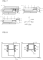
- Figs. 7(a) to 7(c) illustrate the structure and operation of the indoor unit 3 in Working Example 3, and illustrate a flow of air inside the indoor unit 3.
- Fig. 7(a) is a perspective view illustrating the structure of an indoor unit 3c in its entirety.
- Figs. 7(b) and 7(c) are front views of the indoor unit 3c, which is viewed from the front. Note that the differences between Working Example 1 illustrated in Figs. 5(a) to 5(e) and Working Example 3 illustrated in Figs. 7(a) to 7(c) and between Working Example 2 illustrated in Figs. 6(a) to 6(c) and Working Example 3 illustrated in Figs. 7(a) to 7(c) will be described below.
- a second air inlet 14c is provided through which outside air is sucked.
- the second air inlet 14c is provided at a position different from the position in Working Examples 1 and 2.
- the indoor unit 3c has the first indoor heat exchange units 4a, 4b, and 4c, and the second indoor heat exchange units 5b and 5c accommodated in the indoor unit 3c.
- the indoor unit 3c has a first damper 11c and a second damper 12c accommodated in the indoor unit 3c.
- the second damper 12c is located in the vicinity of the second air inlet 14c.
- the second damper 12c has a shape substantially the same as a shape of the second air inlet 14c. Additionally, the second damper 12c is larger in size than the second air inlet 14c.
- Fig. 7(a) illustrates the example in which the second damper 12c is located below the second air inlet 14c along the right face of the indoor unit 3c. While the second air inlet 14c has a square shape, the second damper 12c also has a square shape.
- the second damper 12c has a width and a length that are both greater than a width and a length of the second air inlet 14c.
- the second damper 12c has an operating means (not illustrated) and operates such that the second damper 12c is brought into any of an open state in which the second damper 12c does not interfere with outside air flowing from the second air inlet 14c into the indoor unit 3c, a closed state in which the second damper 12c closes the second air inlet 14c and stops the outside air from entering the indoor unit 3c, and a half-open state that is intermediate between the open state and the closed state.
- Fig. 7(b) illustrates the example in which the second damper 12c is positioned below the second air inlet 14c and is in an open state in which the second damper 12c does not close the second air inlet 14c.
- Fig. 7(b) illustrates the example in which the second damper 12c is positioned below the second air inlet 14c and is in an open state in which the second damper 12c does not close the second air inlet 14c.
- Fig. 7(b) illustrates the example in which the second damper 12c is positioned below
- FIG. 7(c) illustrates the example in which the second damper 12c has moved and is thus in a closed state in which the second damper 12c closes the second air inlet 14c. Note that, when the second damper 12c is in the closed state, since the second damper 12c is greater in size than the second air inlet 14c, the second damper 12c can completely seal the second air inlet 14c.
- any type of means can be used.
- the operating means of the second damper 12c may be manually operated by a user.
- Figs. 8(a) and 8(b) illustrate an example in which the operating means of the second damper 12c is manually operated.
- slits 20 with protruding portions may be provided at the right face of the indoor unit 3c, and tabs 21 that are movable along the slits 20 may be attached to the second damper 12c, and a user thus can move the tabs 21 to operate the second damper 12c.
- the second damper 12c is brought into the open state by the operating means described above.
- the second damper 12c is brought into the closed state by the operating means described above.
- the protruding portions are also provided at the middle of the respective slits 20, and the second damper 12c can be brought into the half-open state by a user moving the tabs 21 to the middle protruding portions described above.
- the first damper 11c is located inside the indoor unit 3c and between the first air inlet 13 and the second indoor heat exchange units 5b and 5c.
- the first damper 11c is installed in the rear face of the indoor unit 3c below the first air inlet 13.
- the shape and operation of the first damper 11c in the present working example are substantially the same as the shape and operation of the first damper 11b in Working Example 2. However, it is necessary to avoid the first damper 11c from interfering with the second damper 12c as will be described later.
- the first damper 11c has a size large enough to stop the room air sucked through the first air inlet 13 from entering the second indoor heat exchange units 5b and 5c.
- the first damper 11c similarly to Working Example 2, has a width greater than the width of the second indoor heat exchange unit 5b, and a length greater than the distance from the rear face of the indoor unit 3c to the front-side end portion of the second indoor heat exchange unit 5b.
- the first damper 11c needs to have a size such that the first damper 11c does not interfere with the second damper 12c when the second damper 12c is in the closed state and the first damper 11c is in an open state, which will be described later.
- the first damper 11c has an operating means (not illustrated) and operates such that the first damper 11c is brought into any of a closed state in which the first damper 11c stops room air sucked through the first air inlet 13 from entering the second indoor heat exchange units 5b and 5c, an open state in which the first damper 11c does not interfere with the room air entering the second indoor heat exchange units 5b and 5c, and a half-open state that is intermediate between the open state and the closed state.
- Figs. 7(a) and 7(b) illustrate the example in which the first damper 11c is in the closed state.
- Fig. 7(c) illustrates the example in which the first damper 11c is in the open state.
- any type of means can be used. Note that the operating means of the first damper 11c needs to have a size such that the first damper 11c does not interfere with the second damper 12c when the second damper 12c is in the closed state and the first damper 11c is in the open state.
- Figs. 7(b) and 7(c) illustrate a flow of air in the indoor unit 3c when the indoor unit 3c is viewed from the front.
- the second damper 12c is in the open state, while the first damper 11c is in the closed state.
- the second damper 12c is in the closed state, while the first damper 11c is in the open state.
- the first indoor heat exchange units 4a, 4b, and 4c, and the second indoor heat exchange units 5b and 5c are in a state in which the subcooled liquid region is reduced as illustrated by the solid line in Fig. 3 , and accordingly the efficiency of the heat exchanger increases in its entirety.
- the state in the first indoor heat exchange units 4a, 4b, and 4c, and the second indoor heat exchange units 5b and 4c is the same as the state in the existing heat exchanger illustrated by the dotted line in Fig. 3 , into which outside air is not drawn.
- the refrigeration cycle apparatus 100 in the present disclosure has the first indoor heat exchange unit 4 and the second indoor heat exchange unit 5.
- the indoor unit 3 is provided with the first air inlet 13 through which room air is sucked, and the second air inlet 14 through which outside air is sucked. Further, the first damper 11 and the second damper 12 are installed in the indoor unit 3.
- the second damper 12 When the refrigeration cycle apparatus 100 performs heating operation, the second damper 12 is brought into the open state, while the first damper 11 is brought into the closed state, and low-temperature outside air thus enters the second indoor heat exchange unit 5.
- ventilation is provided by drawing the outside air into a room.
- the indoor heat exchange unit 5 the amount of heat exchange between the refrigerant and the outside air increases, and the temperature of outside air entering the indoor unit thus can be quickly increased. Therefore, although ventilation is provided by allowing the outside air to enter the room, a reduction in the heating capacity is less likely to occur.
- the refrigeration cycle apparatus 100 achieves energy saving. Note that, when the outside air temperature is almost equal to the room air temperature, or when the outside air is contaminated, the second damper 12 is brought into the closed state, while the first damper 11 is brought into the open state, and the refrigeration cycle apparatus 100 thus can operate substantially the same as the existing refrigeration cycle apparatus.
- the partition wall 18 can also be provided to more reliably separate room air flowing in the indoor unit 3 from outside air.
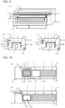
- Figs. 9(a), 9(b), and 9(c) illustrate the structure of the indoor unit 3a in Working Example 1 when the partition wall 18 is provided inside the indoor unit 3a.
- Figs. 9(a), 9(b), and 9(c) illustrate an example in which the partition wall 18 is attached to the rear face of the indoor unit 3a with the first damper 11a located at the tip end portion of the partition wall 18. Therefore, in Figs. 9(a), 9(b), and 9(c) , both the partition wall 18 and the first damper 11a are located between the first air inlet 13 and the second indoor heat exchange unit 5a.
- the first damper 11a operates, for example, such that the first damper 11a rotates about its connection portion with the partition wall 18. Specifically, in Fig. 9(b) , the first damper 11a is in the closed state, and prevents the room air sucked through the first air inlet 13 from flowing to the second heat exchange unit 5. In contrast, in Fig. 9(c) , the first damper 11a has rotated about its connection portion with the partition wall 18 and is thus in the open state. Therefore, the first damper 11a allows the room air sucked through the first air inlet 13 to enter the second heat exchange unit 5.
- the partition wall 18 and the first damper 11a are located in the manner as described above, which helps easily control a flow of air in the indoor unit 3a. This facilitates making use of the capacity of the refrigeration cycle apparatus as designed.
- Figs. 10(a) and 10(b) illustrate the structure of the indoor unit 3b in Working Example 2 when the partition wall 18 is provided inside the indoor unit 3b.
- the partition wall 18 is provided on the left of the second air inlet 14b.
- the second damper 12b is in the open state, and outside air is sucked through the second air inlet 14 into the indoor unit 3b and flows to the second heat exchange unit 5.
- room air is sucked through the first air inlet 13 into the indoor unit 3b, however, this room air flows in a direction limited by the first damper 11b and the partition wall 18, and thus very little amount of the room air flows to the second heat exchange unit 5.
- the first damper 11b is in the open state.
- the first damper 11b moves transversely in the drawings, while the partition wall 18 is provided such that the movement of the first damper 11b described above is allowed. Therefore, even in a case where the partition wall 18 is provided, the first damper 11b still operates properly, and in addition, flows of room air and outside air in the indoor unit 3b can be reliably controlled. This facilitates making use of the capacity of the refrigeration cycle apparatus as designed.
- the refrigeration cycle apparatus of the present disclosure is particularly applicable to performing heating operation while providing ventilation.
Landscapes
- Engineering & Computer Science (AREA)
- Chemical & Material Sciences (AREA)
- Combustion & Propulsion (AREA)
- Mechanical Engineering (AREA)
- General Engineering & Computer Science (AREA)
- Physics & Mathematics (AREA)
- Thermal Sciences (AREA)
- Fluid Mechanics (AREA)
- Air-Flow Control Members (AREA)
- Air Conditioning Control Device (AREA)
Abstract
Description
- The present disclosure relates to a refrigeration cycle apparatus and an indoor unit.
- Some refrigeration cycle apparatus cools or heats air by exchanging heat between the room air and refrigerant flowing in a heat exchanger. In recent years, there is a refrigeration cycle apparatus with a technique to draw outside air into an indoor unit and perform cooling and heating while providing ventilation. (See, for example, Patent Literature 1)
- Patent Literature 1:
Japanese Unexamined Patent Application Publication No. H 11 -257793 - However, in the refrigeration cycle apparatus disclosed in
Patent Literature 1, the indoor unit is provided with a heat exchanger dedicated to ventilation. This limits the size of a heat exchanger that can be used to perform cooling and heating without providing ventilation, and thus may decrease efficiency of the refrigeration cycle apparatus. - The present disclosure has been made to solve the problem described above. It is an object of the present disclosure to provide a refrigeration cycle apparatus that performs cooling and heating, in which it is possible to set whether to provide ventilation and it is also possible to prevent a decrease in efficiency when the refrigeration cycle apparatus does not provide ventilation.
- A refrigeration cycle apparatus according to an embodiment of the present disclosure includes an indoor unit provided with a first air inlet communicating with an inside of a room and a second air inlet communicating with outside of the room; a first heat exchange unit located in a first air flow passage connecting the first air inlet and an air outlet; a second heat exchange unit located in a second air flow passage connecting the second air inlet and the air outlet, the second heat exchange unit being connected to the first heat exchange unit such that the second heat exchange unit is positioned downstream of the first heat exchange unit when the refrigeration cycle apparatus performs heating operation; a first damper capable of adjusting an amount of air entering from the first air flow passage to the second air flow passage; and a second damper provided at the second air inlet and capable of adjusting an amount of air to be sucked from the second air inlet.
- In the refrigeration cycle apparatus according to an embodiment of the present disclosure, it is possible to set whether to provide ventilation. Even when not providing ventilation, the refrigeration cycle apparatus can still exhibit equal performance compared to an indoor heat exchanger installed in some refrigeration cycle apparatus. This can prevent the refrigeration cycle apparatus from decreasing its efficiency regardless of the usage conditions.
-
- [
Fig. 1] Fig. 1 illustrates the configuration of a refrigeration cycle apparatus inEmbodiment 1. - [
Figs. 2] Figs. 2 illustrate operation of an indoor unit inEmbodiment 1. - [
Fig. 3] Fig. 3 illustrates the state in an indoor heat exchanger during heating operation inEmbodiment 1. - [
Fig. 4] Fig. 4 illustrates another configuration of the indoor unit inEmbodiment 1. - [
Figs. 5] Figs. 5 illustrate the structure and operation of, and a flow of air in, an indoor unit in Working Example 1. - [
Figs. 6] Figs. 6 illustrate the structure and operation of, and a flow of air in, an indoor unit in Working Example 2. - [
Figs. 7] Figs. 7 illustrate the structure and operation of, and a flow of air in, an indoor unit in Working Example 3. - [
Figs. 8] Figs. 8 illustrate an operating means of a second damper in Working Example 3. - [
Figs. 9] Figs. 9 illustrate a modification of the indoor unit in Working Example 1. - [
Figs. 10] Figs. 10 illustrate a modification of the indoor unit in Working Example 2. - Embodiments of the present disclosure will be described below with reference to the accompanying drawings. In the drawings, the same or equivalent parts will be denoted by the same reference signs, and redundant descriptions of the same or equivalent parts will be appropriately simplified or omitted. Note that the embodiments described below are not intended to limit the scope of the present disclosure.
-
Fig. 1 illustrates the configuration of arefrigeration cycle apparatus 100 in the present embodiment. Therefrigeration cycle apparatus 100 includes acompressor 1, a four-way valve 2, anindoor unit 3, anexpansion valve 9, and anoutdoor heat exchanger 10. Further inFig. 1 , theindoor unit 3 has a first indoorheat exchange unit 4, a second indoorheat exchange unit 5, and a firstindoor fan 6 accommodated in theindoor unit 3. Note that theoutdoor heat exchanger 10 is accommodated in an outdoor unit (not illustrated) and an outdoor fan is also accommodated in the outdoor unit. - Furthermore, the
refrigeration cycle apparatus 100 includes acontroller 50. Thecontroller 50 issues a command to thecompressor 1, the four-way valve 2, the first air-sending means 6, theexpansion valve 9, afirst damper 11, and asecond damper 12, which will be described later, and the outdoor fan (not illustrated), to control operation of the respective components. - The
compressor 1, the four-way valve 2, the first indoorheat exchange unit 4, the second indoorheat exchange unit 5, theexpansion valve 9, and theoutdoor heat exchanger 10 are connected by pipes, forming a refrigerant circuit. In the refrigerant circuit, refrigerant such as R32 (difluoromethane) circulates. Note that the type of refrigerant to be filled in therefrigeration cycle apparatus 100 is not particularly limited. - In
Fig. 1 , in cooling operation, refrigerant flows in the direction shown by the dotted arrows. That is, refrigerant discharged from thecompressor 1 condenses in theoutdoor heat exchanger 10, is reduced in pressure by theexpansion valve 9, and evaporates in the second indoorheat exchange unit 5 and the first indoorheat exchange unit 4. The refrigerant having evaporated flows back to thecompressor 1. - In contrast, in heating operation, refrigerant flows in the direction shown by the solid arrows. That is, refrigerant discharged from the
compressor 1 condenses in the first indoorheat exchange unit 4 and the second indoorheat exchange unit 5, is reduced in pressure by theexpansion valve 9, and evaporates in theoutdoor heat exchanger 10. The refrigerant having evaporated flows back to thecompressor 1. Switching between the cooling operation and the heating operation is performed by the four-way valve 2 changing the connection in the refrigerant circuit. - The
compressor 1 is, for example, a rotary compressor. The capacity, rated frequency, and other specifications of thecompressor 1 are determined by the type of refrigerant to be filled in the refrigerant circuit, the capacity of therefrigeration cycle apparatus 100, and other factors. Note that thecompressor 1 may be a piston compressor or a scroll compressor. Thecompressor 1 may be operated with a rated frequency by thecontroller 50 or with a variable frequency controlled by an inverter installed in thecontroller 50. - The four-
way valve 2 is configured to switch flow passages, and switches between flow passages depending on whether therefrigeration cycle apparatus 100 performs cooling operation or heating operation. When therefrigeration cycle apparatus 100 performs cooling operation, the four-way valve 2 connects a discharge port of thecompressor 1 and theoutdoor heat exchanger 10, and also connects the first indoorheat exchange unit 4 and a suction port of thecompressor 1. In contrast, when therefrigeration cycle apparatus 100 performs heating operation, the four-way valve 2 connects the discharge port of thecompressor 1 and the first indoorheat exchange unit 4, and also connects theoutdoor heat exchanger 10 and the suction port of thecompressor 1. The connections in the four-way valve 2 are changed by thecontroller 50. - The
indoor unit 3 accommodates the first indoorheat exchange unit 4, the second indoorheat exchange unit 5, and the firstindoor fan 6 in theindoor unit 3. Note that the first indoorheat exchange unit 4 and the second indoorheat exchange unit 5 may be identical indoor heat exchangers to each other, or may be different indoor heat exchangers. There is a structural relationship between the first indoorheat exchange unit 4 and the second indoorheat exchange unit 5, including two points as follows. The first point is that the first indoorheat exchange unit 4 is positioned upstream of the second indoorheat exchange unit 5 in a flow of refrigerant when therefrigeration cycle apparatus 100 performs heating operation, while the second indoorheat exchange unit 5 is positioned downstream of the first indoorheat exchange unit 4 during the heating operation. The second point is that, as will be described later, while room air always flows through the first indoorheat exchange unit 4, outside air or room air flows through the second indoorheat exchange unit 5. - The first indoor
heat exchange unit 4 and the second indoorheat exchange unit 5 are each, for example, a fin-and-tube heat exchanger made up of cooper tubes and aluminum fins fixedly attached to the copper tubes. Refrigerant flows through the inside of the copper tubes, and heat of the refrigerant is thus transmitted to the fins. This allows the refrigerant and air flowing between the fins to exchange heat with each other. Note that, in general, in a fin-and-tube heat exchanger, refrigerant flows through the inside of multiple branches of copper tubes (hereinafter, "paths"). The number of branches of copper tubes (hereinafter, "the number of paths") may be equal or different between the first indoorheat exchange unit 4 and the second indoorheat exchange unit 5. The density and shape of the fins may also be the same or different between the first indoorheat exchange unit 4 and the second indoorheat exchange unit 5. Note that, when the volume of the firstheat exchange unit 4 and the volume of the secondheat exchange unit 5 are considered, the firstheat exchange unit 4 is larger in volume than the secondheat exchange unit 5. As will be described later, when therefrigeration cycle apparatus 100 performs heating operation, a relatively large amount of refrigerant in a gas state and in a two-phase gas-liquid state flows through a first indoorheat exchange unit 4a, while a relatively large amount of refrigerant in a liquid state flows through a second indoorheat exchange unit 4b. In general, refrigerant in a gas state and in a two-phase gas-liquid state fills a larger proportion of the volume of a refrigeration cycle heat exchanger in comparison to refrigerant in a liquid state. Accordingly, the firstheat exchange unit 4 needs to have a volume larger than a volume of the secondheat exchange unit 5. - The first indoor
heat exchange unit 4 and the second indoorheat exchange unit 5 are connected by copper tubes. Note that the first indoorheat exchange unit 4 and the second indoorheat exchange unit 5 may be connected in any manner. For example, provided that the first indoorheat exchange unit 4 and the second indoorheat exchange unit 5 have equal number of paths, their respective paths may be connected to each other. For another example, in a case where the first indoorheat exchange unit 4 has a larger number of paths than the number of paths of the second indoorheat exchange unit 5, some of the paths of the first indoorheat exchange unit 4 may be merged into one that is merged with a path of the second indoorheat exchange unit 5. - The first
indoor fan 6 is, for example, a cross flow fan provided inside theindoor unit 3. The firstindoor fan 6 generates airflow to help blow out the air with its temperature adjusted by the first indoorheat exchange unit 4 and the second indoorheat exchange unit 5 from theindoor unit 3. The firstindoor fan 6 is controlled by thecontroller 50. Note that the firstindoor fan 6 is not limited to the cross flow fan, and any means such as a propeller fan and a sirocco fan may be used as the firstindoor fan 6. - A
first air inlet 13 through which room air is sucked, asecond air inlet 14 through which outside air is sucked, and anair outlet 15 through which air with its temperature adjusted is blown out are formed in theindoor unit 3. For example, outside air is sucked from an air passage hole provided at a wall of a room or from a duct connecting to the outside of the room through thesecond air inlet 14. - Room air sucked through the
first air inlet 13 into theindoor unit 3 passes through the first indoorheat exchange unit 4 and is blown out from theair outlet 15. In contrast, outside air sucked through thesecond air inlet 14 into theindoor unit 3 passes through the second indoorheat exchange unit 5 and is blown out from theair outlet 15. The room air described above flows through an air flow passage, that is, a path connecting thefirst air inlet 13 and theair outlet 15. This path is defined as a firstair flow passage 7. Similarly, the outside air flows through an air flow passage, that is, a path connecting thesecond air inlet 14 and theair outlet 15. This path is defined as a secondair flow passage 8. -
Figs. 2(a) to 2(d) illustrate the states of thefirst damper 11 and thesecond damper 12, and flows of air through the firstair flow passage 7 and the secondair flow passage 8. Thefirst damper 11 is installed in the firstair flow passage 7 at a position at which thefirst damper 11 is capable of adjusting the amount of room air that branches off from the firstair flow passage 7 and flows through the secondair flow passage 8. In contrast, thesecond damper 12 is installed in the vicinity of thesecond air inlet 14 or another position at which thesecond damper 12 is capable of adjusting the amount of outside air to be sucked through theair inlet 14. - An example of the installation position of the
first damper 11 is described below in more detail. As illustrated inFigs. 2(a) and 2(b) , apartition wall 18 may be provided inside theindoor unit 3 to separate the firstair flow passage 7 from the secondair flow passage 8. In this case, there is a hole on a portion of thepartition wall 18 to allow the firstair flow passage 7 and the secondair flow passage 8 to communicate with each other. Thefirst damper 11 is installed at a position at which thefirst damper 11 is capable of opening and closing the hole. Thefirst damper 11 is installed in this manner, and thefirst damper 11 thus can prevent the room air flowing through the firstair flow passage 7 from flowing to the secondheat exchange unit 5, or can adjust the room air described above such that it flows to the secondheat exchange unit 5. - Note that the example has been described above in which the
partition wall 18 is provided in theindoor unit 3, however, thepartition wall 18 may not be necessarily provided as long as a flow of room air can be adjusted by only thefirst damper 11 without thepartition wall 18. Thepartition wall 18 is provided for the purpose of preventing room air from entering the secondheat exchange unit 5 when thefirst damper 11 is in a closed state. Therefore, the structure of thepartition wall 18 is not limited to the example as described above in which thepartition wall 18 separates the firstair flow passage 7 from the secondair flow passage 8 and has a hole on a portion of thepartition wall 18 to allow both the air flow passages to communicate with each other. - A flow of air in the
indoor unit 3 is described below in more detail. InFig. 2(a) , thefirst damper 11 is in a closed state, while thesecond damper 12 is in an open state. In this case, room air sucked through thefirst air inlet 13 enters the first indoorheat exchange unit 4 from the firstair flow passage 7. Outside air sucked through thesecond air inlet 14 enters the second indoorheat exchange unit 5 from the secondair flow passage 8. - In contrast, in
Fig. 2(b) , thefirst damper 11 is in an open state, while thesecond damper 12 is in a closed state. In this case, room air sucked through thefirst air inlet 13 flows to the firstair flow passage 7. Further, since thefirst damper 11 is in an open state, a portion of the sucked room air branches off from the firstair flow passage 7 and then also flows to the secondair flow passage 8. In this case, the room air enters both the first indoorheat exchange unit 4 and the second indoorheat exchange unit 5. - In contrast, in
Fig. 2(c) , thefirst damper 11 is in a closed state, while thesecond damper 12 is in a half-open state. In this case, room air sucked through thefirst air inlet 13 flows to the firstair flow passage 7. Outside air sucked through thesecond air inlet 14 flows to the secondair flow passage 8. Note that thesecond damper 12 is in a half-open sate, and accordingly has a smaller open area of thesecond air inlet 14 compared to an open area in a case ofFig. 2(a) . For this reason, the amount of outside air to be sucked through thesecond air inlet 14 is reduced compared to the amount of outside air in a case ofFig. 2(a) . - In contrast, in
Fig. 2(d) , thefirst damper 11 and thesecond damper 12 are each in a half-open state. In this case, room air sucked through thefirst air inlet 13 passes through the firstair flow passage 7. Note that, since thefirst damper 11 is in a half-open state, a portion of the sucked room air flows to the secondair flow passage 8. Outside air sucked through thesecond air inlet 14, and the portion of the sucked room air flows to the secondair flow passage 8. - The
expansion valve 9 is, for example, a solenoid valve with its opening degree controllable. Theexpansion valve 9 reduces the high pressure of refrigerant having entered theexpansion valve 9 to a low pressure. The opening degree of the solenoid valve is controlled by thecontroller 50. - The
outdoor heat exchanger 10 is, for example, a fin-and-tube heat exchanger. WhileFig. 1 illustrates the example in which there is a singleoutdoor heat exchanger 10, the number of paths may be variable or the density and shape of the fins may be variable, for example, in any location throughout theoutdoor heat exchanger 10. - The
controller 50 is made up of, for example, a central processing unit (CPU), a storage medium having control programs stored in the storage medium, such as a read only memory (ROM), a working memory such as a random access memory (RAM), and a communication circuit. Thecontroller 50 issues a command to thecompressor 1, the four-way valve 2, the first air-sendingmeans 6, theexpansion valve 9, thefirst damper 11, thesecond damper 12, and the outdoor fan in accordance with operational programs stored in advance or signals input by a user of a refrigeration cycle apparatus, and thus controls operation of the respective components. - Subsequently, operation and effects of the
refrigeration cycle apparatus 100 in the present embodiment are described. First, heating operation is described, during which therefrigeration cycle apparatus 100 of the present disclosure produces significant effects. - In the descriptions below, the
first damper 11 and thesecond damper 12 operate automatically by detecting the conditions in a room through a sensor and other devices. In this case, thefirst damper 11 and thesecond damper 12 are brought into any of the states inFigs. 2(a) to 2(d) depending on the outside air temperature and the room air temperature, as well as on contamination status of the room air. - Note that the configuration of the
refrigeration cycle apparatus 100 in the present disclosure is not limited to this, and thefirst damper 11 and thesecond damper 12 may operate in accordance with a signal input through a remote control or other means by a user of therefrigeration cycle apparatus 100, or may be operated manually by the user. - First, circumstances are considered where the outside air temperature is lower than the room air temperature and the room air is contaminated. In this case, as illustrated in
Fig. 2(a) , thefirst damper 11 is in a closed state, while thesecond damper 12 is in an open state. In this case, the room air flows through the firstair flow passage 7 and the first indoorheat exchange unit 4, while the outside air flows through the secondair flow passage 8 and the second indoorheat exchange unit 5. - In this case, since the outside air is supplied into the room, the level of air contamination in the room is reduced. Note that the contaminated air in the room is discharged to the outside from a window or an air vent provided in the room, or from a crack.
- At this time, higher-temperature room air flows through the first indoor
heat exchange unit 4, while lower-temperature outside air flows through the second indoorheat exchange unit 5.Fig. 3 illustrates the state in the first indoorheat exchange unit 4 and the second indoorheat exchange unit 5. Note that, in a case ofFig. 3 , the state in the first indoorheat exchange unit 4 and the second indoorheat exchange unit 5 inFig. 2(a) is illustrated by the solid line. InFig. 3 , high-temperature and high-pressure gas refrigerant compressed in thecompressor 1 enters the first indoorheat exchange unit 4. The high-temperature and high-pressure gas refrigerant exchanges heat with room air and thus becomes two-phase gas-liquid refrigerant. The two-phase gas-liquid refrigerant further exchanges heat with the room air and thus becomes liquid refrigerant. - The refrigerant having become liquid refrigerant enters the second indoor
heat exchange unit 5. Since the outside air temperature is lower than the room air temperature, the difference in temperature between the refrigerant and the outside air increases at the second indoorheat exchange unit 5, and accordingly the amount of heat exchange increases. The refrigerant having become subcooled liquid through the heat exchange flows out from the second indoorheat exchange unit 5. - Descriptions are made on differences in the state between the first indoor
heat exchange unit 4 and the second indoorheat exchange unit 5 in the present disclosure and an existing indoor heat exchanger of some refrigeration cycle apparatus in which outside air is not drawn into an indoor unit.Fig. 3 shows the state in the existing indoor heat exchanger by the dotted line. In the existing heat exchanger, heat is exchanged between refrigerant and high-temperature room air even in the region where the refrigerant has become liquid. That is, there is a relatively small difference in temperature between the air and the refrigerant, and accordingly the amount of heat exchange decreases. - In this case, to ensure a sufficient amount of heat exchange in the liquid region, the subcooled liquid region in the heat exchanger is enlarged, while the two-phase gas-liquid region in the heat exchanger is reduced. In general, the heat transfer rate in tubes of a heat exchanger is higher in the two-phase gas-liquid region than in the subcooled liquid region. For this reason, in the existing heat exchanger whose subcooled liquid region is relatively large, the efficiency of this existing heat exchanger decreases and its internal pressure increases.
- In contrast, the first indoor
heat exchange unit 4 and the second indoorheat exchange unit 5 of the present disclosure illustrated by the solid line can still ensure a sufficient amount of heat exchange even in the subcooled liquid region since the second indoorheat exchange unit 5 has a relatively large difference in temperature between refrigerant and outside air. Consequently, the two-phase gas-liquid region in the heat exchanger is larger compared to the existing heat exchanger, and thus the efficiency of the heat exchanger improves. Accordingly, the pressure in the heat exchanger decreases compared to the pressure in a case of the existing heat exchanger. As the pressure in the heat exchanger decreases, the ratio between high-pressure and low-pressure in a refrigeration cycle formed in therefrigeration cycle apparatus 100, that is, the compression ratio in thecompressor 1 decreases, which improves efficiency of thecompressor 1, and leads to energy saving. Further, as the subcooled liquid region is reduced, the amount of refrigerant to be filled in therefrigeration cycle apparatus 100 decreases in its entirety. - In addition, in the second indoor
heat exchange unit 5 where there is a relatively large difference in temperature between refrigerant and outside air, the amount of heat exchange between the refrigerant and the outside air increases, and the temperature of outside air entering the indoor unit thus can be quickly increased. With this configuration, although ventilation is provided by allowing the outside air to enter the room, problems such as a reduction in the heating capacity and a decrease in blowing temperature are less likely to occur. - Next, circumstances are considered where room air is not contaminated. In this case, as illustrated in
Fig. 2(b) , thesecond damper 12 is in a closed state, while thefirst damper 11 is in an open state. In this case, the room air flows to the first indoorheat exchange unit 4 and the second indoorheat exchange unit 5. At this time, the states in the first indoorheat exchange unit 4 and the second indoorheat exchange unit 5 are the same as the states in a case of the existing heat exchanger in which outside air is not drawn into the indoor unit, and therefore descriptions of the states in the first indoorheat exchange unit 4 and the second indoorheat exchange unit 5 are omitted. - Subsequently, a case is described where room air is contaminated at a relatively low level. In this case, as illustrated in
Fig. 2(c) , thesecond damper 12 is in a half-open state, while thefirst damper 11 is in a closed state. In this case, the amount of outside air that flows through the secondair flow passage 8 and the second indoorheat exchange unit 5 is smaller compared to the amount of the outside air when thesecond damper 12 is in an open state illustrated inFig. 2(a) . The reason for this is that thesecond damper 12 is in a half-open state, which results in an air flow resistance. - In the state illustrated in
Fig. 2(c) , ventilation is provided in the room more slowly compared to the case illustrated inFig. 2(a) . Also in this case, the difference in temperature between refrigerant and outside air increases at the second indoorheat exchange unit 5, and the efficiency of the heat exchanger thus improves in its entirety as illustrated inFig. 3 . In addition, since the amount of outside air decreases, problems such as a reduction in heating capacity and a decrease in blowing temperature are even less likely to occur. - Furthermore, when the outside air temperature is higher than the room air temperature, the
first damper 11 may be brought into a half-open state as illustrated inFig. 2(d) . In this case, room air sucked through thefirst air inlet 13 partially enters the secondair flow passage 8. In the secondair flow passage 8, the room air described above and outside air sucked through thesecond air inlet 14 are mixed together. At this time, since the room air temperature is lower than the outside air temperature, the mixed air has a temperature lower than the outside air temperature. The mixed air described above enters the second indoorheat exchange unit 5. - In a case where the outside air temperature is relatively high, when the outside air is allowed to enter the second indoor
heat exchange unit 5, the difference in temperature between the outside air and refrigerant decreases, and accordingly the amount of heat exchange decreases. However, the room air and the outside air are mixed together as illustrated inFig. 2(d) , and the mixed air with its temperature decreased is thus allowed to enter the second indoorheat exchange unit 5. With this configuration, therefrigeration cycle apparatus 100 can provide ventilation, while preventing a decrease in the amount of heat exchange. - The operation of the
refrigeration cycle apparatus 100 has been described above. However, the examples illustrated inFigs. 2(a) to 2(d) are not intended to limit the operation of therefrigeration cycle apparatus 100. Therefrigeration cycle apparatus 100 can also operate differently from the operation illustrated inFigs. 2(a) to 2(d) . For example, both thefirst damper 11 and thesecond damper 12 may be each brought into an open state. In this case, even when the outside air temperature is relatively high, it is still possible, in addition to increasing the amount of ventilation, to slow the decrease in the amount of heat exchange in the second indoorheat exchange unit 5. - In
Figs. 2(a) to 2(d) , each of thefirst damper 11 and thesecond damper 12 is in any of an open state, a closed state, or a half-open state. However, it is still possible for each of thefirst damper 11 and thesecond damper 12 to be in an intermediate state between the open state and the half-open state or in an intermediate state between the closed state and the half-open state. The opening degree of each of thefirst damper 11 and thesecond damper 12 can be set minutely in the manner as described above, and therefrigeration cycle apparatus 100 thus can adjust the amount of ventilation in response to the circumstances in the room, and can optimize as possible the efficiency of the heat exchanger. - Note that, while the case where the
refrigeration cycle apparatus 100 performs heating operation has been described above, therefrigeration cycle apparatus 100 can also perform cooling operation. In this case, circumstances are considered where the outside air temperature is higher than the room air temperature and the room air is contaminated. In this case, as illustrated inFig. 2(a) , thesecond damper 12 is in an open state, while thefirst damper 11 is in a closed state, and room air flows through the first indoorheat exchange unit 4, while outside air flows through the second indoorheat exchange unit 5. - At this time, low-temperature refrigerant in a two-phase gas-liquid state with its pressure reduced by the
expansion valve 9 flows through the second indoorheat exchange unit 5. As high-temperature outside air enters the second indoorheat exchange unit 5, the difference in temperature between the outside air and the refrigerant increases, and accordingly the amount of heat exchange increases. At this time, the high temperature of the outside air is decreased quickly to a low temperature through the heat exchange. Therefore, therefrigeration cycle apparatus 100 can provide ventilation by supplying the outside air, in addition to preventing the reduction in cooling capacity and the increase in blowing temperature. - During cooling operation, the
refrigeration cycle apparatus 100 also changes the states of thefirst damper 11 and thesecond damper 12 in response to the contamination status of the room air, and the outside air temperature and the room air temperature. This allows therefrigeration cycle apparatus 100 to provide the proper amount of ventilation, in addition to maintaining its cooling capacity and efficiency under various circumstances. - As explained above, the
refrigeration cycle apparatus 100 in the present embodiment operates thefirst damper 11 and thesecond damper 12 in response to the contamination status of room air, the outside air temperature, the room air temperature, and other factors. This allows therefrigeration cycle apparatus 100 to provide the proper amount of ventilation, in addition to reducing variations in its blowing temperature. - In a case where the
refrigeration cycle apparatus 100 does not provide ventilation, therefrigeration cycle apparatus 100 can feed room air to the second indoorheat exchange unit 5 by operating thefirst damper 11 and thesecond damper 12. In this case, the condition of air inside theindoor unit 3, that is, a mechanism to exchange heat between the air and refrigerant is the same as the mechanism to exchange heat between air and refrigerant in an indoor unit of an existing refrigeration cycle apparatus. Therefore, even when it is unnecessary to provide ventilation, therefrigeration cycle apparatus 100 can still achieve efficiency almost equal to efficiency of the existing refrigeration cycle apparatus. - Note that the configuration of the
refrigeration cycle apparatus 100 explained above is merely an example of the configuration of therefrigeration cycle apparatus 100 in the present disclosure. Various modifications can be made without departing from the scope of the present disclosure. -
Fig. 4 illustrates another configuration example of theindoor unit 3. InFig. 4 , a second indoor fan 16 is provided. It is thus possible to adjust the amount of outside air that enters the second indoorheat exchange unit 5 independently of the amount of room air that enters the first indoorheat exchange unit 4. In addition, inFig. 4 , afilter 17 is installed at thesecond air inlet 14. Thefilter 17 removes dust and dirt contained in the outside air. This allows cleaner outside air to be supplied into a room. - Working Examples of the structure and operation of the
indoor unit 3 will be described below. Note that a flow of air inside theindoor unit 3 is additionally described. -
Figs. 5(a) to 5(e) illustrate the structure and operation of theindoor unit 3 of therefrigeration cycle apparatus 100 in Working Example 1, and illustrate a flow of air inside theindoor unit 3.Fig. 5(a) is a perspective view illustrating the structure of anindoor unit 3a in its entirety.Fig. 5(b) is a front view of theindoor unit 3a, which is viewed from the front.Fig. 5(c) is a rear view of theindoor unit 3a, which is viewed from the rear.Figs. 5(d) and 5(e) are left-side views of theindoor unit 3a, which is viewed from the left. - In the
indoor unit 3a illustrated inFigs. 5(a) to 5(e) , thefirst air inlet 13 is provided at the top face of theindoor unit 3a, through which room air is sucked, and asecond air inlet 14a is provided at the rear face of theindoor unit 3a, through which outside air is sucked. At the lower portion of the front face of theindoor unit 3a, theair outlet 15 is provided. Theair outlet 15 is provided with an air-flow direction adjustment means configured to adjust the direction of airflow blown out from theindoor unit 3a. Further, theindoor unit 3a has first indoorheat exchange units heat exchange unit 5a, and the firstindoor fan 6 accommodated in theindoor unit 3a. - Furthermore, the
indoor unit 3a has a first damper 11a and asecond damper 12a accommodated in theindoor unit 3a. Thesecond damper 12a is located in the vicinity of thesecond air inlet 14a. Thesecond damper 12a has a shape substantially the same as a shape of thesecond air inlet 14a. Additionally, thesecond damper 12a is slightly larger in size than thesecond air inlet 14a. In the example illustrated inFig. 5(c) , thesecond damper 12a is located immediately below thesecond air inlet 14a. While thesecond air inlet 14a has a rectangular shape, thesecond damper 12a also has a rectangular shape. Thesecond damper 12a has a width and a height that are both greater than a width and a height of thesecond air inlet 14a. - Furthermore, the
second damper 12a has an operating means (not illustrated) and operates such that thesecond damper 12a is brought into any of an open state in which thesecond damper 12a does not interfere with outside air flowing from thesecond air inlet 14a into theindoor unit 3a, a closed state in which thesecond damper 12a closes thesecond air inlet 14a and stops the outside air from entering theindoor unit 3a, and a half-open state that is intermediate between the open state and the closed state. When thesecond damper 12a is in the closed state, since thesecond damper 12a is greater in size than thesecond air inlet 14a, thesecond damper 12a can completely seal thesecond air inlet 14a. - Note that, as the operating means configured to change the state of the
second damper 12a, any type of means can be used. For example, a rotational shaft may be attached to one end of thesecond damper 12a, and the rotational shaft may be rotated by power to operate thesecond damper 12a. - The first damper 11a is located inside the
indoor unit 3a and between thefirst air inlet 13 and the second indoorheat exchange unit 5a. In the example illustrated inFigs. 5(a) and 5(d) , the first damper 11a is installed in the rear face of theindoor unit 3a below thefirst air inlet 13. - While the shape of the first damper 11a is not particularly limited, the first damper 11a has a size large enough to stop the room air sucked through the
first air inlet 13 from entering the second indoorheat exchange unit 5a. In the example inFigs. 5(a) and 5(d) , the first damper 11a has a width greater than a width of thefirst air inlet 13, and a length greater than the distance from the rear face of theindoor unit 3a to the second indoorheat exchange unit 5a. The first damper 11a has the size as described above, and when the first damper 11a is in a closed state, which will be described later, the first damper 11a thus can stop the room air from entering the second indoorheat exchange unit 5a. - Furthermore, the first damper 11a has an operating means (not illustrated) and operates such that the first damper 11a is brought into any of a closed state in which the first damper 11a stops room air sucked through the
first air inlet 13 from entering the second indoorheat exchange unit 5a, an open state in which the first damper 11a does not interfere with the room air entering the second indoorheat exchange unit 5a, and a half-open state that is intermediate between the open state and the closed state. When the first damper 11a is in the closed state, since the first damper 11a has the width greater than the width of thefirst air inlet 13, and the length greater than a length from the rear face of theindoor unit 3a to the second indoorheat exchange unit 5a, the first damper 11a can stop the room air from entering the second indoorheat exchange unit 5a. - Note that, as the operating means configured to change the state of the first damper 11a, any type of means can be used. For example, a rotational shaft may be attached to one end of the first damper 11a, and the rotational shaft may be rotated by power to operate the first damper 11a.
-
Figs. 5(d) and 5(e) illustrate airflow in theindoor unit 3a when theindoor unit 3a is viewed from the leftward direction. InFig. 5(d) , thesecond damper 12a is in the open state, while the first damper 11a is in the closed state. In contrast, inFig. 5(e) , thesecond damper 12a is in the closed state, while the first damper 11a is in the open state. - In the state illustrated in
Fig. 5(d) , the room air enters theindoor unit 3a from thefirst air inlet 13, while the outside air enters theindoor unit 3a from thesecond air inlet 14a. Note that the room air sucked through thefirst air inlet 13 is interfered with by the first damper 11a, and thus enters the first indoorheat exchange units heat exchange unit 5a. Since thesecond damper 12a is in the open state, the outside air is sucked through thesecond air inlet 14a and enters the second indoorheat exchange unit 5a. - At this time, when the
refrigeration cycle apparatus 100 operates in heating mode, the first indoorheat exchange units heat exchange unit 5a are in a state in which the subcooled liquid region is reduced as illustrated by the solid line inFig. 3 , and accordingly the efficiency of the heat exchanger increases in its entirety. - In contrast, in
Fig. 5(e) , thesecond damper 12a is in the closed state, while the first damper 11a is in the open state. In the state illustrated inFig. 5(e) , while the room air enters from thefirst air inlet 13, the outside air does not enter from thesecond air inlet 14a since thesecond damper 12a seals thesecond air inlet 14a. The room air having entered from thefirst air inlet 13 enters the first indoorheat exchange units heat exchange unit 5a. - At this time, when the
refrigeration cycle apparatus 100 operates in heating mode, the state in the first indoorheat exchange units heat exchange unit 5a are brought into the same state as in the existing heat exchanger illustrated by the dotted line inFig. 3 , into which outside air is not drawn. -
Figs. 6(a) to 6(c) illustrate the structure and operation of theindoor unit 3 in Working Example 2, and illustrate a flow of air inside theindoor unit 3.Fig. 6(a) is a perspective view illustrating the structure of anindoor unit 3b in its entirety.Figs. 6(b) and 6(c) are rear views of theindoor unit 3b, which is viewed from the rear. Note that the differences between Working Example 1 illustrated inFigs. 5(a) to 5(e) and Working Example 2 illustrated inFigs. 6(a) to 6(c) will be described below. - At the rear face of the
indoor unit 3b illustrated inFigs. 6(a) to 6(c) , asecond air inlet 14b is provided through which outside air is sucked. In Working Example 2, the location and shape of thesecond air inlet 14b are different from the location and shape of the second air inlet in Working Example 1. Theindoor unit 3b has first indoorheat exchange units heat exchange units indoor unit 3b. In Working Example 2, the shapes of the first indoorheat exchange unit 4 and the second indoorheat exchange unit 5 are different from the shapes of the first indoorheat exchange unit 4 and the second indoorheat exchange unit 5 in Working Example 1. - Further, the
indoor unit 3b has afirst damper 11b and asecond damper 12b accommodated in theindoor unit 3b. Thesecond damper 12b is located in the vicinity of thesecond air inlet 14b. Thesecond damper 12b has a shape substantially the same as a shape of thesecond air inlet 14b. Additionally, thesecond damper 12b is larger in size than thesecond air inlet 14b.Fig. 6(b) illustrates the example in which thesecond damper 12b is located on the right of thesecond air inlet 14b along the rear face of theindoor unit 3b. While thesecond air inlet 14b has a substantially square shape, thesecond damper 12b also has a substantially square shape. Thesecond damper 12b has a width and a length that are both greater than a width and a length of thesecond air inlet 14b. - Furthermore, the
second damper 12b has an operating means (not illustrated) and operates such that thesecond damper 12b is brought into any of an open state in which thesecond damper 12b does not interfere with outside air flowing from thesecond air inlet 14b into theindoor unit 3b, a closed state in which thesecond damper 12b closes thesecond air inlet 14b and stops the outside air from entering theindoor unit 3b, and a half-open state that is intermediate between the open state and the closed state.Fig. 6(b) illustrates the example in which thesecond damper 12b is positioned on the right of thesecond air inlet 14b and in an open state in which thesecond damper 12b does not close thesecond air inlet 14b. In contrast,Fig. 6(c) illustrates the example in which thesecond damper 12b has moved to a position at which thesecond damper 12b closes thesecond air inlet 14b from the inner side, and is in a closed state in which thesecond damper 12b closes thesecond air inlet 14b. Note that, when thesecond damper 12b is in the closed state, since thesecond damper 12b is greater in size than thesecond air inlet 14b, thesecond damper 12b can completely seal thesecond air inlet 14b. - Note that, as the operating means configured to change the state of the
second damper 12b, any type of means can be used. For example, a rail may be installed for thesecond damper 12b to move thesecond damper 12b along the rail. - The
first damper 11b is located inside theindoor unit 3b and between thefirst air inlet 13 and the second indoorheat exchange units Figs. 6(a) and 6 (b) illustrate the example in which thefirst damper 11b is installed in the rear face of theindoor unit 3b below thefirst air inlet 13. - Note that, while the shape of the
first damper 11b is not particularly limited, thefirst damper 11b has a size large enough to stop the room air sucked through thefirst air inlet 13 from entering the second indoorheat exchange units Figs. 6(a) and 6(b) , thefirst damper 11b has a width greater than a width of the second indoorheat exchange unit 5b, and a length greater than the distance from the rear face of theindoor unit 3b to the front-side end portion of the second indoorheat exchange unit 5b. Thefirst damper 11b has the size as described above, and when thefirst damper 11b is in a closed state, which will be described later, thefirst damper 11b thus can stop the room air from entering the second indoorheat exchange units - Furthermore, the
first damper 11b has an operating means (not illustrated) and operates such that thefirst damper 11b is brought into any of a closed state in which thefirst damper 11b stops room air sucked through thefirst air inlet 13 from entering the second indoorheat exchange units first damper 11b does not interfere with the room air entering the second indoorheat exchange units Figs. 6(a) and 6(b) illustrate the example in which thefirst damper 11b is in the closed state. At this time, thefirst damper 11b has the width greater than the width of the second indoorheat exchange unit 5b, and the length greater than the distance from the rear face of theindoor unit 3b to the front-side end portion of the second indoorheat exchange unit 5b. This configuration can stop the room air from entering the second indoorheat exchange units Fig. 6(c) illustrates the example in which thefirst damper 11b is in the open state. At this time, since thefirst damper 11b is not positioned between thefirst air inlet 13 and the second indoorheat exchange units first damper 11b allows the room air to enter the second indoorheat exchange units - Note that, as the operating means configured to change the state of the
first damper 11b, any type of means can be used. For example, a rail may be installed for thefirst damper 11b to move thefirst damper 12b along the rail. -
Figs. 6(b) and 6(c) illustrate airflow in theindoor unit 3b when theindoor unit 3b is viewed from the rear. InFig. 6(b) , thesecond damper 12b is in the open state, while thefirst damper 11b is in the closed state. In contrast, inFig. 6(c) , thesecond damper 12b is in the closed state, while thefirst damper 11b is in the open state. - In the state illustrated in
Fig. 6(b) , the room air enters theindoor unit 3b from thefirst air inlet 13, while the outside air enters theindoor unit 3b from thesecond air inlet 14b. Note that the room air sucked through thefirst air inlet 13 is interfered with by thefirst damper 11b, and thus enters the first indoorheat exchange units heat exchange units second damper 12b is in the open state, the outside air is sucked through thesecond air inlet 14b and enters the second indoorheat exchange units - At this time, when the
refrigeration cycle apparatus 100 operates in heating mode, the first indoorheat exchange units heat exchange units Fig. 3 , and accordingly the efficiency of the heat exchanger increases in its entirety. - In contrast, in
Fig. 6(c) , thesecond damper 12b is in the closed state, while thefirst damper 11b is in the open state. In the state illustrated inFig. 6(c) , while the room air enters from thefirst air inlet 13, the outside air does not enter from thesecond air inlet 14b since thesecond damper 12b seals thesecond air inlet 14b. The room air having entered from thefirst air inlet 13 enters the first indoorheat exchange units heat exchange units - At this time, when the
refrigeration cycle apparatus 100 operates in heating mode, the first indoorheat exchange units heat exchange units Fig. 3 , into which outside air is not drawn. -
Figs. 7(a) to 7(c) illustrate the structure and operation of theindoor unit 3 in Working Example 3, and illustrate a flow of air inside theindoor unit 3.Fig. 7(a) is a perspective view illustrating the structure of anindoor unit 3c in its entirety.Figs. 7(b) and 7(c) are front views of theindoor unit 3c, which is viewed from the front. Note that the differences between Working Example 1 illustrated inFigs. 5(a) to 5(e) and Working Example 3 illustrated inFigs. 7(a) to 7(c) and between Working Example 2 illustrated inFigs. 6(a) to 6(c) and Working Example 3 illustrated inFigs. 7(a) to 7(c) will be described below. - On the right of the
indoor unit 3c illustrated inFigs. 7(a) to 7(c) , asecond air inlet 14c is provided through which outside air is sucked. In Working Example 3, thesecond air inlet 14c is provided at a position different from the position in Working Examples 1 and 2. Similarly to Working Example 2, theindoor unit 3c has the first indoorheat exchange units heat exchange units indoor unit 3c. - Further, the
indoor unit 3c has afirst damper 11c and asecond damper 12c accommodated in theindoor unit 3c. Thesecond damper 12c is located in the vicinity of thesecond air inlet 14c. Thesecond damper 12c has a shape substantially the same as a shape of thesecond air inlet 14c. Additionally, thesecond damper 12c is larger in size than thesecond air inlet 14c.Fig. 7(a) illustrates the example in which thesecond damper 12c is located below thesecond air inlet 14c along the right face of theindoor unit 3c. While thesecond air inlet 14c has a square shape, thesecond damper 12c also has a square shape. Thesecond damper 12c has a width and a length that are both greater than a width and a length of thesecond air inlet 14c. - Furthermore, the
second damper 12c has an operating means (not illustrated) and operates such that thesecond damper 12c is brought into any of an open state in which thesecond damper 12c does not interfere with outside air flowing from thesecond air inlet 14c into theindoor unit 3c, a closed state in which thesecond damper 12c closes thesecond air inlet 14c and stops the outside air from entering theindoor unit 3c, and a half-open state that is intermediate between the open state and the closed state.Fig. 7(b) illustrates the example in which thesecond damper 12c is positioned below thesecond air inlet 14c and is in an open state in which thesecond damper 12c does not close thesecond air inlet 14c. In contrast,Fig. 7(c) illustrates the example in which thesecond damper 12c has moved and is thus in a closed state in which thesecond damper 12c closes thesecond air inlet 14c. Note that, when thesecond damper 12c is in the closed state, since thesecond damper 12c is greater in size than thesecond air inlet 14c, thesecond damper 12c can completely seal thesecond air inlet 14c. - Note that, as the operating means configured to change the state of the
second damper 12c, any type of means can be used. For example, the operating means of thesecond damper 12c may be manually operated by a user.Figs. 8(a) and 8(b) illustrate an example in which the operating means of thesecond damper 12c is manually operated. As illustrated inFigs. 8(a) and 8(b) , slits 20 with protruding portions may be provided at the right face of theindoor unit 3c, andtabs 21 that are movable along theslits 20 may be attached to thesecond damper 12c, and a user thus can move thetabs 21 to operate thesecond damper 12c. - In
Fig. 8(a) , thesecond damper 12c is brought into the open state by the operating means described above. InFig. 8(b) , thesecond damper 12c is brought into the closed state by the operating means described above. Note that, inFigs. 8(a) and 8(b) , the protruding portions are also provided at the middle of therespective slits 20, and thesecond damper 12c can be brought into the half-open state by a user moving thetabs 21 to the middle protruding portions described above. - The
first damper 11c is located inside theindoor unit 3c and between thefirst air inlet 13 and the second indoorheat exchange units Figs. 7(a) and 7(b) , thefirst damper 11c is installed in the rear face of theindoor unit 3c below thefirst air inlet 13. The shape and operation of thefirst damper 11c in the present working example are substantially the same as the shape and operation of thefirst damper 11b in Working Example 2. However, it is necessary to avoid thefirst damper 11c from interfering with thesecond damper 12c as will be described later. - Note that, while the shape of the
first damper 11c is not particularly limited, thefirst damper 11c has a size large enough to stop the room air sucked through thefirst air inlet 13 from entering the second indoorheat exchange units Figs. 7(a) and 7(b) , similarly to Working Example 2, thefirst damper 11c has a width greater than the width of the second indoorheat exchange unit 5b, and a length greater than the distance from the rear face of theindoor unit 3c to the front-side end portion of the second indoorheat exchange unit 5b. - In addition, the
first damper 11c needs to have a size such that thefirst damper 11c does not interfere with thesecond damper 12c when thesecond damper 12c is in the closed state and thefirst damper 11c is in an open state, which will be described later. - Furthermore, the
first damper 11c has an operating means (not illustrated) and operates such that thefirst damper 11c is brought into any of a closed state in which thefirst damper 11c stops room air sucked through thefirst air inlet 13 from entering the second indoorheat exchange units first damper 11c does not interfere with the room air entering the second indoorheat exchange units Figs. 7(a) and 7(b) illustrate the example in which thefirst damper 11c is in the closed state. In contrast,Fig. 7(c) illustrates the example in which thefirst damper 11c is in the open state. - As the operating means configured to change the state of the
first damper 11c, any type of means can be used. Note that the operating means of thefirst damper 11c needs to have a size such that thefirst damper 11c does not interfere with thesecond damper 12c when thesecond damper 12c is in the closed state and thefirst damper 11c is in the open state. -
Figs. 7(b) and 7(c) illustrate a flow of air in theindoor unit 3c when theindoor unit 3c is viewed from the front. InFig. 7(b) , thesecond damper 12c is in the open state, while thefirst damper 11c is in the closed state. In contrast, inFig. 7(c) , thesecond damper 12c is in the closed state, while thefirst damper 11c is in the open state. - In the state illustrated in
Fig. 7(b) , room air enters theindoor unit 3c from thefirst air inlet 13, while outside air enters theindoor unit 3c from thesecond air inlet 14c. Note that the room air sucked through thefirst air inlet 13 is interfered with by thefirst damper 11c, and thus enters the first indoorheat exchange units heat exchange units second damper 12c is in the open state, the outside air is sucked through thesecond air inlet 14c and enters the second indoorheat exchange units - At this time, when the
refrigeration cycle apparatus 100 operates in heating mode, the first indoorheat exchange units heat exchange units Fig. 3 , and accordingly the efficiency of the heat exchanger increases in its entirety. - In contrast, in
Fig. 7(c) , thesecond damper 12c is in the closed state, while thefirst damper 11c is in the open state. In the state illustrated inFig. 7(c) , while room air enters from thefirst air inlet 13, outside air does not enter from thesecond air inlet 14c since thesecond damper 12c seals thesecond air inlet 14c. The room air having entered from thefirst air inlet 13 enters the first indoorheat exchange units heat exchange units - At this time, when the
refrigeration cycle apparatus 100 operates in heating mode, the state in the first indoorheat exchange units heat exchange units Fig. 3 , into which outside air is not drawn. - As explained above, the
refrigeration cycle apparatus 100 in the present disclosure has the first indoorheat exchange unit 4 and the second indoorheat exchange unit 5. Theindoor unit 3 is provided with thefirst air inlet 13 through which room air is sucked, and thesecond air inlet 14 through which outside air is sucked. Further, thefirst damper 11 and thesecond damper 12 are installed in theindoor unit 3. - When the
refrigeration cycle apparatus 100 performs heating operation, thesecond damper 12 is brought into the open state, while thefirst damper 11 is brought into the closed state, and low-temperature outside air thus enters the second indoorheat exchange unit 5. With this configuration, ventilation is provided by drawing the outside air into a room. In addition, in the indoorheat exchange unit 5, the amount of heat exchange between the refrigerant and the outside air increases, and the temperature of outside air entering the indoor unit thus can be quickly increased. Therefore, although ventilation is provided by allowing the outside air to enter the room, a reduction in the heating capacity is less likely to occur. - Further, as the efficiency of the second indoor
heat exchange unit 5 improves, the ratio between high-pressure and low-pressure in therefrigeration cycle apparatus 100 decreases, therefrigeration cycle apparatus 100 achieves energy saving. Note that, when the outside air temperature is almost equal to the room air temperature, or when the outside air is contaminated, thesecond damper 12 is brought into the closed state, while thefirst damper 11 is brought into the open state, and therefrigeration cycle apparatus 100 thus can operate substantially the same as the existing refrigeration cycle apparatus. - Note that, in Working Examples 1, 2, and 3, the
first damper 11 and thesecond damper 12 have been described as being in the open state or the closed state, however, thefirst damper 11 and thesecond damper 12 may be each brought into the half-open state. This allows for adjustment of the amount of outside air and the amount of room air entering the second indoorheat exchange unit 5. - In Working Examples 1, 2, and 3, the
partition wall 18 can also be provided to more reliably separate room air flowing in theindoor unit 3 from outside air. -
Figs. 9(a), 9(b), and 9(c) illustrate the structure of theindoor unit 3a in Working Example 1 when thepartition wall 18 is provided inside theindoor unit 3a. -
Figs. 9(a), 9(b), and 9(c) illustrate an example in which thepartition wall 18 is attached to the rear face of theindoor unit 3a with the first damper 11a located at the tip end portion of thepartition wall 18. Therefore, inFigs. 9(a), 9(b), and 9(c) , both thepartition wall 18 and the first damper 11a are located between thefirst air inlet 13 and the second indoorheat exchange unit 5a. - Note that, in the case illustrated in
Figs. 9(a), 9(b), and 9(c) , the first damper 11a operates, for example, such that the first damper 11a rotates about its connection portion with thepartition wall 18. Specifically, inFig. 9(b) , the first damper 11a is in the closed state, and prevents the room air sucked through thefirst air inlet 13 from flowing to the secondheat exchange unit 5. In contrast, inFig. 9(c) , the first damper 11a has rotated about its connection portion with thepartition wall 18 and is thus in the open state. Therefore, the first damper 11a allows the room air sucked through thefirst air inlet 13 to enter the secondheat exchange unit 5. - The
partition wall 18 and the first damper 11a are located in the manner as described above, which helps easily control a flow of air in theindoor unit 3a. This facilitates making use of the capacity of the refrigeration cycle apparatus as designed. -
Figs. 10(a) and 10(b) illustrate the structure of theindoor unit 3b in Working Example 2 when thepartition wall 18 is provided inside theindoor unit 3b. - In
Figs. 10(a) and 10(b) , thepartition wall 18 is provided on the left of thesecond air inlet 14b. InFig. 10(a) , thesecond damper 12b is in the open state, and outside air is sucked through thesecond air inlet 14 into theindoor unit 3b and flows to the secondheat exchange unit 5. At this time, room air is sucked through thefirst air inlet 13 into theindoor unit 3b, however, this room air flows in a direction limited by thefirst damper 11b and thepartition wall 18, and thus very little amount of the room air flows to the secondheat exchange unit 5. - In
Fig. 10(b) , thefirst damper 11b is in the open state. WhenFig. 10(a) and Fig. 10(b) are compared to each other, thefirst damper 11b moves transversely in the drawings, while thepartition wall 18 is provided such that the movement of thefirst damper 11b described above is allowed. Therefore, even in a case where thepartition wall 18 is provided, thefirst damper 11b still operates properly, and in addition, flows of room air and outside air in theindoor unit 3b can be reliably controlled. This facilitates making use of the capacity of the refrigeration cycle apparatus as designed. - The refrigeration cycle apparatus of the present disclosure is particularly applicable to performing heating operation while providing ventilation.
- 1: compressor, 2: four-way valve, 3, 3, 3b, 3c: indoor unit, 4, 4a, 4b, 4c: first indoor heat exchange unit, 5, 5a, 5b, 5c: second indoor heat exchange unit, 6: first indoor fan, 7: first air flow passage, 8: second air flow passage, 9: expansion valve, 10: outdoor heat exchanger, 11, 11a, 11b, 11c: first damper, 12, 12a, 12b, 12c: second damper, 13: first air inlet, 14, 14a, 14b, 14c: second air inlet, 15: air outlet, 16: second indoor fan, 17: filter, 18: partition wall, 20: slit, 21: tab, 50: controller, 100: refrigeration cycle apparatus
Claims (8)
- A refrigeration cycle apparatus comprising:an indoor unit provided with a first air inlet communicating with an inside of a room and a second air inlet communicating with outside of the room;a first heat exchange unit located in a first air flow passage connecting the first air inlet and an air outlet;a second heat exchange unit located in a second air flow passage connecting the second air inlet and the air outlet, the second heat exchange unit being connected to the first heat exchange unit such that the second heat exchange unit is positioned downstream of the first heat exchange unit when the refrigeration cycle apparatus performs heating operation;a first damper capable of adjusting an amount of air entering from the first air flow passage to the second air flow passage; anda second damper provided at the second air inlet and capable of adjusting an amount of air to be sucked from the second air inlet.
- The refrigeration cycle apparatus of claim 1, whereina partition wall is provided inside the indoor unit, the partition wall separating the first air flow passage from the second air flow passage,the partition wall is provided with a communication portion through which the first air flow passage and the second air flow passage communicate with each other, andthe first damper is installed at the communication portion, and is capable of adjusting an amount of air flowing through the communication portion.
- The refrigeration cycle apparatus of claim 1 or 2, comprising:a first fan configured to suck air from the first air inlet and feed the air to the first heat exchange unit; anda second fan configured to suck outside air from the second air inlet and feed the air to the second heat exchange unit.
- The refrigeration cycle apparatus of any one of claims 1 to 3, wherein a filter removing dust and dirt is installed at the second air inlet.
- The refrigeration cycle apparatus of any one of claims 1 to 4, wherein the second damper is larger in size than the second air inlet.
- The refrigeration cycle apparatus of any one of claims 1 to 5, wherein the first heat exchange unit has a volume larger than a volume of the second heat exchange unit.
- The refrigeration cycle apparatus of any one of claims 1 to 6, wherein the second air inlet is provided at a rear face of the indoor unit.
- The refrigeration cycle apparatus of any one of claims 1 to 6, wherein the second air inlet is provided at a lateral face of the indoor unit.
Applications Claiming Priority (1)
| Application Number | Priority Date | Filing Date | Title |
|---|---|---|---|
| PCT/JP2021/016303 WO2022224406A1 (en) | 2021-04-22 | 2021-04-22 | Refrigeration cycle apparatur and indoor unit |
Publications (2)
| Publication Number | Publication Date |
|---|---|
| EP4328512A1 true EP4328512A1 (en) | 2024-02-28 |
| EP4328512A4 EP4328512A4 (en) | 2024-05-22 |
Family
ID=83722104
Family Applications (1)
| Application Number | Title | Priority Date | Filing Date |
|---|---|---|---|
| EP21937899.9A Withdrawn EP4328512A4 (en) | 2021-04-22 | 2021-04-22 | REFRIGERATION CYCLE AND INDOOR UNIT |
Country Status (5)
| Country | Link |
|---|---|
| US (1) | US20240230139A9 (en) |
| EP (1) | EP4328512A4 (en) |
| JP (1) | JP7466764B2 (en) |
| CN (1) | CN117157493A (en) |
| WO (1) | WO2022224406A1 (en) |
Family Cites Families (11)
| Publication number | Priority date | Publication date | Assignee | Title |
|---|---|---|---|---|
| JP3456021B2 (en) * | 1994-07-29 | 2003-10-14 | 株式会社デンソー | Vehicle air conditioner |
| JPH0914690A (en) * | 1995-06-27 | 1997-01-17 | Mitsubishi Electric Corp | Indoor unit of air conditioner |
| US5826443A (en) * | 1997-12-06 | 1998-10-27 | Ares; Roland | Heat pump with heat-pipe enhancement and with primary system reheat |
| JPH11257793A (en) * | 1998-03-12 | 1999-09-24 | Hitachi Ltd | Air conditioner with ventilation function |
| JP2004294026A (en) * | 2003-03-28 | 2004-10-21 | Fujitsu General Ltd | Air conditioner |
| KR100519306B1 (en) * | 2003-05-28 | 2005-10-10 | 엘지전자 주식회사 | Air-conditioner system with ventilation |
| JP5199041B2 (en) * | 2008-11-27 | 2013-05-15 | シャープ株式会社 | Air conditioner |
| JP5838316B2 (en) * | 2011-05-26 | 2016-01-06 | パナソニックIpマネジメント株式会社 | Air conditioner for vehicles |
| JP2014066476A (en) * | 2012-09-27 | 2014-04-17 | Panasonic Corp | Heat exchange device and heating element storage device using the same |
| KR101613963B1 (en) * | 2014-12-08 | 2016-04-20 | 엘지전자 주식회사 | Clothes treating apparatus with a heat pump system |
| CN105485783B (en) * | 2016-01-28 | 2018-07-03 | 海信(广东)空调有限公司 | Air conditioner indoor unit |
-
2021
- 2021-04-22 JP JP2023515977A patent/JP7466764B2/en active Active
- 2021-04-22 US US18/546,499 patent/US20240230139A9/en not_active Abandoned
- 2021-04-22 CN CN202180097105.1A patent/CN117157493A/en active Pending
- 2021-04-22 WO PCT/JP2021/016303 patent/WO2022224406A1/en not_active Ceased
- 2021-04-22 EP EP21937899.9A patent/EP4328512A4/en not_active Withdrawn
Also Published As
| Publication number | Publication date |
|---|---|
| JP7466764B2 (en) | 2024-04-12 |
| EP4328512A4 (en) | 2024-05-22 |
| JPWO2022224406A1 (en) | 2022-10-27 |
| US20240133576A1 (en) | 2024-04-25 |
| WO2022224406A1 (en) | 2022-10-27 |
| US20240230139A9 (en) | 2024-07-11 |
| CN117157493A (en) | 2023-12-01 |
Similar Documents
| Publication | Publication Date | Title |
|---|---|---|
| US9500396B2 (en) | Oil separator and air conditioner using the same | |
| US11047584B2 (en) | Air conditioner | |
| CN107327929B (en) | Vertical air conditioner and control method thereof | |
| CN105980178A (en) | Heat pump system for vehicle | |
| CN102597647B (en) | Air conditioner | |
| CN215001922U (en) | Indoor unit of air conditioner | |
| JP6750240B2 (en) | Air conditioner | |
| CN215001903U (en) | Indoor unit of air conditioner | |
| EP3764020B1 (en) | Indoor unit and air conditioner | |
| EP3382295B1 (en) | Indoor unit of air conditioner | |
| JP2002267204A (en) | Dehumidifier | |
| CN214949389U (en) | Indoor unit of air conditioner | |
| EP4328512A1 (en) | Refrigeration cycle apparatur and indoor unit | |
| WO2021229794A1 (en) | Air conditioner indoor unit and air conditioner | |
| JP7450807B2 (en) | air conditioner | |
| CN107327930A (en) | The control method of floor air conditioner and floor air conditioner | |
| CN110805958B (en) | Air conditioner indoor unit, air conditioner and control method | |
| CN112577102B (en) | Air Conditioner | |
| JPWO2023170734A5 (en) | ||
| JP2011231952A (en) | Air conditioner | |
| KR102944110B1 (en) | Air conditioning system including a heat pump with a reheat function | |
| JP2020063860A (en) | Air conditioning system | |
| KR20210121437A (en) | Air-conditioner | |
| JP2024087326A (en) | Refrigeration equipment | |
| KR20080009848A (en) | Air Conditioning Synchronous Multi Air Conditioner |
Legal Events
| Date | Code | Title | Description |
|---|---|---|---|
| STAA | Information on the status of an ep patent application or granted ep patent |
Free format text: STATUS: THE INTERNATIONAL PUBLICATION HAS BEEN MADE |
|
| PUAI | Public reference made under article 153(3) epc to a published international application that has entered the european phase |
Free format text: ORIGINAL CODE: 0009012 |
|
| STAA | Information on the status of an ep patent application or granted ep patent |
Free format text: STATUS: REQUEST FOR EXAMINATION WAS MADE |
|
| 17P | Request for examination filed |
Effective date: 20231017 |
|
| AK | Designated contracting states |
Kind code of ref document: A1 Designated state(s): AL AT BE BG CH CY CZ DE DK EE ES FI FR GB GR HR HU IE IS IT LI LT LU LV MC MK MT NL NO PL PT RO RS SE SI SK SM TR |
|
| A4 | Supplementary search report drawn up and despatched |
Effective date: 20240422 |
|
| RIC1 | Information provided on ipc code assigned before grant |
Ipc: F24F 7/007 20060101ALI20240416BHEP Ipc: F24F 7/003 20210101ALI20240416BHEP Ipc: F24F 1/0063 20190101ALI20240416BHEP Ipc: F24F 11/74 20180101AFI20240416BHEP |
|
| 18W | Application withdrawn |
Effective date: 20240619 |