EP4328448B1 - Membranpumpe - Google Patents
Membranpumpe Download PDFInfo
- Publication number
- EP4328448B1 EP4328448B1 EP23214388.3A EP23214388A EP4328448B1 EP 4328448 B1 EP4328448 B1 EP 4328448B1 EP 23214388 A EP23214388 A EP 23214388A EP 4328448 B1 EP4328448 B1 EP 4328448B1
- Authority
- EP
- European Patent Office
- Prior art keywords
- chamber
- pump
- outlet
- inlet
- valve
- Prior art date
- Legal status (The legal status is an assumption and is not a legal conclusion. Google has not performed a legal analysis and makes no representation as to the accuracy of the status listed.)
- Active
Links
Images


Classifications
-
- F—MECHANICAL ENGINEERING; LIGHTING; HEATING; WEAPONS; BLASTING
- F04—POSITIVE - DISPLACEMENT MACHINES FOR LIQUIDS; PUMPS FOR LIQUIDS OR ELASTIC FLUIDS
- F04B—POSITIVE-DISPLACEMENT MACHINES FOR LIQUIDS; PUMPS
- F04B43/00—Machines, pumps, or pumping installations having flexible working members
- F04B43/02—Machines, pumps, or pumping installations having flexible working members having plate-like flexible members, e.g. diaphragms
- F04B43/025—Machines, pumps, or pumping installations having flexible working members having plate-like flexible members, e.g. diaphragms two or more plate-like pumping members in parallel
- F04B43/026—Machines, pumps, or pumping installations having flexible working members having plate-like flexible members, e.g. diaphragms two or more plate-like pumping members in parallel each plate-like pumping flexible member working in its own pumping chamber
-
- F—MECHANICAL ENGINEERING; LIGHTING; HEATING; WEAPONS; BLASTING
- F04—POSITIVE - DISPLACEMENT MACHINES FOR LIQUIDS; PUMPS FOR LIQUIDS OR ELASTIC FLUIDS
- F04B—POSITIVE-DISPLACEMENT MACHINES FOR LIQUIDS; PUMPS
- F04B53/00—Component parts, details or accessories not provided for in, or of interest apart from, groups F04B1/00 - F04B23/00 or F04B39/00 - F04B47/00
- F04B53/10—Valves; Arrangement of valves
- F04B53/1037—Flap valves
- F04B53/1047—Flap valves the valve being formed by one or more flexible elements
-
- F—MECHANICAL ENGINEERING; LIGHTING; HEATING; WEAPONS; BLASTING
- F04—POSITIVE - DISPLACEMENT MACHINES FOR LIQUIDS; PUMPS FOR LIQUIDS OR ELASTIC FLUIDS
- F04B—POSITIVE-DISPLACEMENT MACHINES FOR LIQUIDS; PUMPS
- F04B43/00—Machines, pumps, or pumping installations having flexible working members
- F04B43/02—Machines, pumps, or pumping installations having flexible working members having plate-like flexible members, e.g. diaphragms
-
- F—MECHANICAL ENGINEERING; LIGHTING; HEATING; WEAPONS; BLASTING
- F04—POSITIVE - DISPLACEMENT MACHINES FOR LIQUIDS; PUMPS FOR LIQUIDS OR ELASTIC FLUIDS
- F04B—POSITIVE-DISPLACEMENT MACHINES FOR LIQUIDS; PUMPS
- F04B53/00—Component parts, details or accessories not provided for in, or of interest apart from, groups F04B1/00 - F04B23/00 or F04B39/00 - F04B47/00
- F04B53/10—Valves; Arrangement of valves
- F04B53/1037—Flap valves
- F04B53/1047—Flap valves the valve being formed by one or more flexible elements
- F04B53/106—Flap valves the valve being formed by one or more flexible elements the valve being a membrane
- F04B53/1065—Flap valves the valve being formed by one or more flexible elements the valve being a membrane fixed at its centre
Definitions
- the invention relates to a diaphragm pump with a pumping chamber, wherein the pumping chamber is connected to an inlet chamber via an inlet valve and to an outlet chamber via an outlet valve.
- the invention also relates to a device for conveying fluids with a diaphragm pump.
- Diaphragm pumps which have a pump head which is essentially connected to a drive.
- the pump head has several, for example four, pump chambers, each of which is sealed from a drive chamber by means of a pump diaphragm.
- the respective pump diaphragm is connected via an associated pump element to a wobble plate arranged in the drive chamber.
- a wobble movement of the wobble plate causes the pump diaphragm to undergo a wobble, axially periodic pumping movement.
- the wobble plate is seated on a drive pin of a drive shaft connected to the drive.
- the drive pin is inclined relative to the longitudinal axis of the drive shaft and is connected to the wobble plate via a ball bearing.
- an outlet chamber is arranged centrally and an inlet chamber is arranged concentrically to the outlet chamber around the outlet chamber.
- a diaphragm pump with at least one pumping chamber is known.
- the pumping chamber is connected to an inlet chamber via an inlet valve and to an outlet chamber via an outlet valve, wherein the inlet valve has an inlet opening that can be closed by an inlet valve body, and the outlet valve has an outlet opening that can be closed by an outlet valve body.
- the outlet opening surrounds the inlet opening, or the inlet opening surrounds the outlet opening.
- WO 2013/032587 A1 describes a multi-valve compressor head having a housing defining an inlet chamber in selective communication with a cavity via a plurality of one-way inlet valves and an outlet chamber selectively communicating with the cavity via a plurality of one-way outlet valves.
- the housing also defines an inlet port for the entry of gas into the inlet chamber and an outlet port for expelling compressed gas from the outlet chamber.
- the multi-valve compressor head is in operative communication with a reciprocating diaphragm that draws gas into the inlet chamber and then into the cavity during the diaphragm's intake stroke, while expelling compressed gas from the cavity and through the outlet port during the diaphragm's exhaust stroke.
- DE 198 33 286 A1 describes a piston and cylinder air compressor having a valve plate between a top end of the cylinder and a cylinder head.
- the valve plate has a generally diametrically disposed recess receiving a suction valve reed, the valve being disposed above openings on at least one side of the recess, and the device is configured to minimize the operating clearance of the compressor.
- US 5,141,409 A describes a compression machine that can be used as a compressor, pump, or actuator.
- the machine includes a housing that houses a flexible diaphragm.
- the interior of the housing is divided into a compression chamber and a backpressure chamber by the diaphragm, which consists of a diaphragm spring or bellows.
- the diaphragm is moved back and forth to compress the fluid in the compression chamber and force it out of the compression chamber.
- the backpressure chamber is sealed with a pressurized gas.
- the pressure in the backpressure chamber opposes the pressure in the compression chamber and is maintained at about half the pressure that exists in the compression chamber during compression to suppress flexion of the diaphragm.
- Diaphragm pumps are used primarily in the chemical, pharmaceutical, and biotechnology industries, where the pumped media can be very expensive. Therefore, it is desirable that no or only a small residual volume of the pumped medium remains in the diaphragm pump after the pumping process. Furthermore, completely filling such diaphragm pumps with the fluid without air inclusions is beneficial for pumping performance.
- EP 3 327 287 A1 known diaphragm pump which has also proven itself in principle, is that the provision of an outlet opening surrounding the inlet opening or the provision of an inlet opening surrounding the outlet opening places relatively high demands on the design of the diaphragm pump, in particular on the design of individual inlet chambers which are connected to an inlet valve.
- the object of the present invention is therefore to improve the known diaphragm pumps with regard to the residual emptying and/or the venting of the pump chambers, whereby a simple structure and/or a simple design is sought.
- the invention is based on the basic idea of selecting the positioning of two outlet valves in the pumping chamber and one inlet valve in the pumping chamber more effectively in order to improve residual emptying and/or venting of the pumping chamber, but also to simplify the design.
- the invention is the first to recognize that providing two outlet valves in addition to the inlet valve can lead to a simpler design if the two outlet valves and the inlet valve are arranged in the corners of any triangle.
- a direct spatial relationship between outlet openings and inlet openings was necessary, for example by surrounding the inlet opening.
- the invention has, among other things, broken the prejudice that an offset arrangement of the outlet valves to the inlet valve does not allow for an improvement in the diaphragm pump.
- the invention is primarily based on a substantially special arrangement of an inlet valve and two outlet valves of a pumping chamber, by means of which the residual quantity of pumped medium and also the air remaining in the pumping chamber after the pumping process has ended can be reduced and even complete emptying is possible.
- One of the outlet valves can be arranged in the upper region of the pumping chamber with respect to the direction of gravitational acceleration, and the other outlet valve can be arranged in the lower region of the pumping chamber with respect to the direction of gravitational acceleration.
- the inlet valve is offset from the outlet valves of a respective pumping chamber, so that an advantageous placement of the outlet valves can be achieved.
- the inlet valve can be arranged next to or to the side of the lower of the two outlet valves.
- the diaphragm pump can empty and/or vent itself to the greatest extent possible, in particular automatically, an improved flow distribution can be made possible with a simpler design of the diaphragm pump.
- central axis or central axis of the diaphragm pump encompasses an axis that extends substantially transversely to the front plate, the valve plate, and/or the end plate (the central axis or central axis may extend substantially parallel to the normal of the front plate, the valve plate, and/or the end plate) and may be arranged substantially centrally to one of the plates.
- the central axis or central axis may extend centrally through an inlet, which is arranged centrally, in particular in a front plate.
- the term "longitudinal axis" of the pumping chamber encompasses an axis that runs, in particular, transversely to the valve plate (essentially parallel to the normal of the valve plate).
- the longitudinal axis is arranged essentially centrally to the pumping chamber, in particular essentially centrally to the pumping diaphragm.
- the longitudinal axis of the pumping chamber runs essentially parallel to the central axis of the diaphragm pump.
- the diaphragm pump has at least one pumping chamber, wherein the pumping chamber is connected to an inlet chamber via an inlet valve and to an outlet chamber via two outlet valves, wherein the outlet chamber is annular.
- the inlet valve has an inlet opening that can be closed by an inlet valve body, and each outlet valve has an outlet opening that can be closed by an outlet valve body. closable outlet opening.
- Two outlet valves are provided for the pump chamber.
- a projection of straight connecting lines, which connect adjacent outlet valves to one another, onto a projection plane transverse to the longitudinal axis of the pump chamber has no intersection points with inlet valves.
- the inlet chamber can be provided substantially centrally.
- the diaphragm pump has a pumping chamber, preferably two, and particularly preferably three, four or more pumping chambers.
- This pumping chamber or the plurality of pumping chambers can, particularly preferably, be cyclically, in particular periodically, changed in volume by an external force.
- at least one wall of the chamber volume is formed by a diaphragm, which is preferably made of one or more elastic materials, for example, plastic, rubber, elastomer, Silicone or an equivalent material, which may in particular also include one or more composite materials for increased stability and service life.
- the pump chamber can be dimensioned with regard to the maximum volume to be maintained in the pump chamber so that this maximum volume corresponds exactly to the fluid volume to be pumped within one pump stroke.
- larger pump chambers are also conceivable, which could, for example, improve the flow behavior, the efficiency of the diaphragm pump, or reduce production costs.
- a valve body within the scope of the description can in particular be formed by an elastic membrane, which generally at least partially opens the valve opening assigned to the valve body when a suitable pressure difference is applied.
- Possible materials for the valve body include, for example, metals, but in particular also plastic, rubber, elastomer, silicone or an equivalent material, which in particular can also comprise or be formed from one or more composite materials.
- a membrane is understood here in particular to be a plate which usually has elastic and/or resilient properties, whereby these elastic and/or resilient properties can also be present only in sections, for example in the edge region.
- the diaphragm can be flat in sections, but in a preferred embodiment, it is curved in the sections where it seals a pump chamber, whereby the curved section can be adapted to the stroke.
- a valve control can control the opening and closing of the valves or influence the optimization of the pumping process.
- the inlet valve and/or the outlet valve is an umbrella valve.
- An umbrella valve is understood to be a valve in which the valve body is formed by an umbrella.
- a number includes the provision of exactly the number of elements designated by the number, although further identical or similar elements are not excluded. If, for example, the description describes that a pumping chamber has two outlet valves, the pumping chamber can have exactly two, but also three, four or more Exhaust valves. The same applies to the intake valve. A pumping chamber can have exactly one intake valve, two, or even three, four, or more intake valves. It is possible for pumping chambers to have a different number of intake and/or exhaust valves.
- An inlet chamber within the scope of the description functions to hold the fluid to be pumped.
- the inlet opening can be formed directly in a wall of the inlet chamber. This enables a compact design of the diaphragm pump, particularly if, in a further preferred embodiment, the inlet opening opens directly into the pumping chamber. It is possible to provide an inlet channel between the inlet chamber and the pumping chamber, which connects the inlet chamber to the pumping chamber. This creates the possibility of designing the position of the inlet chamber within the diaphragm pump relative to the pumping chamber more freely.
- the inlet chamber is connected directly to the pumping chamber via the inlet opening without the interposition of an inlet channel, so that an additional design of an inlet channel can be omitted.
- An outlet chamber within the scope of the description serves to collect and bundle the pumped fluid, in particular for further transmission to a central outlet of the diaphragm pump, particularly in the case of multiple pump chambers and/or outlet valves.
- the outlet opening can be formed directly in a wall of the outlet chamber. This enables a compact design of the diaphragm pump, in particular if, in a further preferred embodiment, the outlet opening opens directly into the pump chamber. It is possible to provide an outlet channel between the outlet chamber and the pump chamber, which connects the outlet chamber to the pump chamber. This creates the possibility of designing the position of the outlet chamber within the diaphragm pump relative to the pump chamber more freely.
- the outlet chamber is connected directly to the pump chamber via the outlet opening without the interposition of an outlet channel, which can simplify the design of the diaphragm pump.
- an outlet valve is arranged in one edge region of the pumping chamber and an outlet valve is arranged in the opposite edge region of the pumping chamber. This allows the outlet valves to be effectively positioned to achieve improved residual fluid evacuation and venting.
- One of the edge regions can be an "upper region” of the pumping chamber, and the other of the edge regions can be a “lower region” of the pumping chamber.
- the terms “upper region” and “lower region” encompass two regions of the pumping chamber located in opposite edge regions. of the pump chamber.
- the term “upper region” functionally encompasses the placement of the outlet valve such that at least one outlet opening is provided, which is arranged as close as possible to the upper edge of the pump chamber.
- the direction “top” or “upper” refers to the direction of gravity when the diaphragm pump is installed and in the operating position.
- the direction “upper” region describes an edge region of the pump chamber that is further spaced in the direction of gravity than the "lower region”.
- the arrangement of the outlet valves in the upper or lower region encompasses positioning such that one or more outlet openings assigned to the outlet valve are arranged in the upper or lower edge region of the pump chamber.
- the inlet valve is positioned closer to the center axis of the diaphragm pump than the two outlet valves. This allows the inlet chamber to be centrally located and surrounded by the outlet chamber, which allows the outlet chamber to be positioned below the inlet chamber relative to the direction of gravity, further improving the residual emptying of the entire diaphragm pump.
- a vertical line describes a line that runs transversely to the central axis of the diaphragm pump or transversely to the longitudinal axis of the pump chamber.
- the vertical line can run parallel to the axis of gravitational acceleration, with the diaphragm pump being considered in the installed and operational state.
- the inlet valve of the pumping chamber is arranged off-center in the cross-section of the pumping chamber. This allows for an offset of the inlet valve, which can create the most free choice possible for the arrangement of the two outlet valves. Essentially, the inlet valve can be offset into a region of the pumping chamber, so that the outlet valves can be positioned more effectively and, at the same time, the connection of the pumping chamber by means of the outlet valves and the inlet valve to the inlet chamber and the outlet chamber is improved.
- off-center in the sense of the description includes a position indication that essentially corresponds to the center of the cross-section and/or the center of gravity of the cross-section, wherein a view along the longitudinal axis of the Diaphragm pump is present, insofar as it is described that the inlet valve is not located on an axis through the center of the cross section or on an axis through the center of gravity of the cross section.
- the outlet valves are arranged in a circular or circular segment shape.
- the outlet valves can be arranged essentially in a circular or circular segment shape on a valve plate, which simplifies the manufacture of the diaphragm pump.
- the outlet valves are arranged in a circular or circular segment shape around a central axis of the diaphragm pump.
- the circular or circular segment-shaped arrangement of the outlet valves can lead to a reduced design effort for an outlet chamber.
- a circular (segment-shaped) design can enable the outlet chamber to exhibit rotational invariance.
- the diaphragm pump has more than one pumping chamber, wherein the arrangement of the inlet valve and the two outlet valves of the pumping chambers essentially has rotational invariance with respect to an angle of less than 360° around the central axis of the diaphragm pump. If multiple pumping chambers are used, rotational invariance can be created, which, in addition to a simple structure or design, enables easy handling or assembly of the diaphragm pump. For example, it can be provided that a rotational invariance of 360° per number of pumping chambers can be achieved.
- an annular outlet chamber is provided.
- the outlet chamber can surround the inlet chamber, and the sealing of the outlet chamber can be limited to just one chamber, if possible.
- a common outlet chamber and a common inlet chamber can be provided, with the outlet chamber surrounding the inlet chamber and no region of the outlet chamber being arranged between two inlet chambers.
- the shape of the outlet chamber and/or inlet chamber can be simple.
- the cross-section of the pumping chamber has at least one straight section on a side wall.
- This allows an enlargement of the pumping chamber compared to a completely curved side wall.
- a completely curved side wall in the upper or lower region provides direct positioning arrangements for the outlet valves by having one inlet valve at the highest point and the other The outlet valve should be positioned at the lowest point of the pumping chamber; this is where the air is trapped or the fluid flows, but venting or residual drainage can also be achieved in straight sections.
- the offset arrangement also allows for an enlargement of the pumping chamber by providing straight sections of the side wall, particularly in the upper and/or lower areas.
- multiple pump chambers are provided, and the pump chambers are arranged in a grid of columns and rows.
- the pump chambers can also be arranged on different levels.
- the grid-like arrangement of the pump chambers essentially one above and one below the other, allows for an arrangement in which the inlet valve can be offset from a central area to effectively position the two outlet valves.
- the invention also provides a device for conveying fluids with a diaphragm pump as described in the description and/or the claims, wherein a pump head is provided with a drive chamber and a drive, and the pump chamber is sealed from the drive chamber by means of a pump diaphragm. If two or more pump chambers are provided, the pump chambers can each be sealed from the drive chamber by means of a pump diaphragm. In a preferred embodiment, the pump diaphragm can be set into a periodic axial pumping movement via an associated pump element.
- outlet opening not only describes a single opening, but is also used to represent a sum of individual openings that are delimited from one another.
- the outlet opening is segmented into several outlet opening sections that are spaced apart from one another transversely to the longitudinal axis of the pumping chamber with respect to the projection plane.
- the outlet opening sections of an outlet valve can preferably be circular or circular segment-shaped.
- the outlet opening sections belong to an outlet valve by closing the outlet opening sections with a common valve body.
- the outlet opening or the outlet opening sections can extend in one direction such that the extent of the outlet opening or the area in which the outlet opening sections of an outlet valve are located corresponds essentially to 1/5 to 1/3 of the width and/or height of the pumping chamber. This allows a high pump throughput to be achieved.
- the term "inlet opening” does not only encompass a single opening; rather, the inlet opening can be formed by inlet opening sections that are delimited from one another.
- the inlet opening is segmented into a plurality of inlet opening sections that are spaced apart from one another with respect to the projection plane transverse to the longitudinal axis of the pumping chamber.
- the inlet opening sections can preferably be arranged in a circular shape or in the shape of a circular segment in a projection plane transverse to the longitudinal axis of the pumping chamber.
- the inlet opening sections belong to an inlet valve by closing the inlet opening sections by a common valve body.
- the inlet chamber has a wall at its vertically lower end, which is configured such that the wall is substantially flush with the lower part of the inlet opening of at least one inlet valve.
- one or more lowest-lying inlet valves merge with the wall of the inlet chamber with the respective lower region of their respective inlet opening in such a way that the inlet chamber can be completely emptied via the inlet valves, and residual fluid is conveyed from the inlet chamber to the outlet chamber during the pumping process.
- the outlet chamber has a wall at its lower vertically directed region, which is configured such that the wall is substantially flush with the lower part of the outlet opening of at least one outlet valve.
- one or more lowest-lying outlet valves merge with the wall of the outlet chamber with the respective lower region of their respective outlet opening in such a way that the outlet chamber can be completely emptied via the outlet valves, and any remaining fluid is pumped from the outlet chamber out of the diaphragm pump during the pumping process.
- outlet valves of the diaphragm pump are designed similarly and particularly preferably have the same shape of the outlet opening and/or the same shape of the valve body.
- inlet valves of the diaphragm pump are designed similarly to one another and particularly preferably have the same shape of the inlet opening and/or the same shape of the valve body.
- an inlet valve plate is provided in or on which the inlet valves are arranged spatially separated.
- the diaphragm pump has four pumping chambers.
- the inlet valve plate has four spatially separated inlet valves.
- the inlet valve plate has four spatially separated inlet valves arranged in a ring.
- an outlet valve plate is provided in or on which the outlet valves are arranged spatially separated.
- the diaphragm pump has four pump chambers.
- the outlet valve plate has eight spatially separated outlet valves.
- the outlet valve plate has eight spatially separated outlet valves arranged in a ring.
- a valve plate is provided in or on which both the inlet valves and the outlet valves are arranged.
- a front plate also referred to as a pump housing, and a valve plate are provided.
- the valve plate can be arranged between the front plate on one side and a membrane support part carrying the pump membrane, for example a membrane housing cover on the other side.
- the inlet chamber or inlet chambers can be at least partially formed in the front plate.
- the inlet chamber or inlet chambers are formed by the front plate and valve plate being in contact with one another, in that recesses formed in the front plate are covered at the rear by the valve plate.
- the outlet chamber can be at least partially formed in the front plate.
- the front plate and valve plate being in contact with one another, in that recesses formed in the front plate are covered at the rear by the valve plate.
- the inlet valve or inlet valves and the outlet valves can be arranged on the valve plate.
- the pump chamber or pump chambers can be at least partially formed in the valve plate.
- the valve plate can be essentially flat. A profile on the edge, particularly for interaction with a corresponding profile on the front plate, can be provided.
- Fig. 1 shows the pump head 2 of a diaphragm pump 1.
- the diaphragm pump 1 forms part of a device for conveying a fluid.
- the pump head 2 has a front plate 3, also referred to as a chamber housing, a valve plate 4 and an end plate 5, also referred to as a membrane carrier, with pump membranes 6, which are connected via pump elements with a Fig. 2 connected to a swashplate not shown.
- a central inlet 7 is provided in this embodiment, which opens into a central inlet chamber 8.
- an outlet 9 is provided, which is connected to an outlet chamber 10, which is annular in this embodiment and surrounds the inlet chamber 8.
- the valve plate 4 closes the inlet chamber 8 of the front plate 3 and the outlet chamber 10 of the front plate 3.
- the valve plate 4 has four inlet valves 15, which are designed as umbrella valves.
- the inlet chamber 8 is connected to the pump chamber 12 via an inlet opening 16 assigned to the inlet valve 15.
- the inlet opening 16 is segmented and has several inlet opening sections 16a.
- An inlet valve 15 is provided for each pumping chamber 12.
- Each pumping chamber 12 has two outlet valves 17.
- the two outlet valves 17 and the inlet valve 15 form a triangle in a projection onto a projection plane transverse to the longitudinal axis L of the pump chamber 12, which runs essentially parallel to a central axis M of the diaphragm pump 1, as shown in Fig. 3 is shown.
- Fig. 3 It can also be seen that adjacent outlet valves 17 on the valve plate 4 can be connected with straight connecting lines and a projection of these onto a projection plane transverse to the longitudinal axis L of the pump chamber 12 is free of intersection with the inlet valves 15.
- the two outlet valves 17 of a pumping chamber are arranged in opposite edge regions of the pumping chamber 12.
- One of the two outlet valves 17 is arranged in an upper region of the pumping chamber 12, while the other of the two outlet valves 17 is arranged in a lower region of the pumping chamber 12.
- the upper of the two outlet valves 17 allows venting of the pumping chamber 12. Residual emptying is possible using the lower of the two outlet valves 17.
- the inlet valve 15 of a pumping chamber 12 is arranged laterally offset from one of the two outlet valves 17.
- the inlet valves 15 are arranged closer to the central axis M of the diaphragm pump 1 than the outlet valves 17 of the pumping chambers 12.
- the two outlet valves 17 of a pumping chamber 12 are arranged offset from one another with respect to a vertical line running essentially along section A-A or parallel thereto.
- the inlet valve 15 is arranged off-center with respect to the cross-section of the pumping chamber 12.
- the outlet valves 17 of the diaphragm pump 1 are arranged in a circle around the central axis M of the diaphragm pump 1.
- valve plate 4 With respect to the valve plate 4, there is a rotational invariance of 90° around the central axis M of the diaphragm pump 1.
- the four pumping chambers 12 are arranged in a grid of columns and rows, with the pumping chambers 12 being arranged one above and next to each other.
- the Fig. 4 is a comparison with the Fig. 3 A differently designed cross-section of the pump chambers 12 for a further embodiment of the diaphragm pump 1 can be seen. Except for the cross-section of the pump chambers 12, the embodiments are otherwise identical and correspond to one another, so that no repetition is necessary here.
- the cross-section of the pump chamber 12 in Fig. 4 The embodiment shown has straight sections 20 on the side wall of the pumping chamber 12, which has an intersection point with the vertical and/or horizontal of a cross section of the pumping chamber 12.
- the swash plate 21 shown is connected via a ball bearing 22 to a pin 23 of a drive shaft 24.
- the pin 23 is inclined relative to the longitudinal axis 25 of the drive shaft 24 in order to generate a wobbling movement of the swash plate 21.
- the connection between the drive axis and the swash plate 21 is arranged in the region of a drive chamber 26 located upstream of the end plate 5.
- the inlet chamber 8 is sealed off from the outlet chamber 10 by a seal 27, which in the example is designed as a cord ring seal.
- the outer boundary of the outlet chamber 10 is sealed off by a seal 28, which in the example is also designed as a cord ring seal.
- the swash plate 21 By rotating the drive shaft 24 about its longitudinal axis 25, the swash plate 21 is set into a circumferential wobbling motion due to the inclination of the pin 23, without rotating with the drive shaft 24.
- the wobbling motion of the swash plate 21 sets the pump diaphragms 6 in a periodic axial pumping motion, by which negative pressure is generated in the pump chambers 12 alternately in the intake stroke by the movement towards the drive chamber 26 and positive pressure is generated in the exhaust stroke by a movement towards the front plate 3.
- the inlet valve 15 Due to the downstream arrangement of the valve shield of the inlet valve 15, the inlet valve 15 opens and the corresponding outlet valve 17 closes automatically when negative pressure prevails in the associated pump chamber 12. When excess pressure prevails in the pump chamber 12, the associated inlet valve 15 closes and the corresponding outlet valve 17 opens automatically. This pumps the pumped medium out of the pump chamber 12 through the outlet chamber 10 to the outlet 9.
Landscapes
- Engineering & Computer Science (AREA)
- Mechanical Engineering (AREA)
- General Engineering & Computer Science (AREA)
- Reciprocating Pumps (AREA)
Description
- Die Erfindung betrifft eine Membranpumpe mit einer Pumpkammer, wobei die Pumpkammer über ein Einlassventil mit einer Einlasskammer und über ein Auslassventil mit einer Auslasskammer verbunden ist. Die Erfindung betrifft auch eine Vorrichtung zum Fördern von Fluiden mit einer Membranpumpe.
- Aus
DE 101 17 531 A1 und ausDE 20 2006 020 237 U1 sind Membranpumpen bekannt, die einen im Wesentlichen mit einem Antrieb verbundenen Pumpenkopf aufweisen. Der Pumpenkopf weist mehrere, beispielsweise vier Pumpkammern auf, die jeweils mittels einer Pumpmembran gegenüber einer Antriebskammer abgedichtet sind. Die jeweilige Pumpmembran steht dabei über ein zugeordnetes Pumpelement mit einer in der Antriebskammer angeordneten Taumelscheibe in Verbindung. Dabei wird durch eine Taumelbewegung der Taumelscheibe die Pumpmembran in eine taumelnde axial periodische Pumpbewegung versetzt. Die Taumelscheibe sitzt auf einem Antriebszapfen einer mit dem Antrieb verbundenen Antriebswelle. Der Antriebszapfen ist dabei gegenüber der Längsachse der Antriebswelle geneigt und mit der Taumelscheibe über ein Kugellager verbunden. Bei den Membranpumpen nachDE 101 17 531 A1 undDE 20 2006 020 237 U1 ist eine Auslasskammer zentrisch und eine Einlasskammer konzentrisch zu der Auslasskammer um die Auslasskammer herum angeordnet. - Aus
EP 3 327 287 A1 ist eine Membranpumpe mit mindestens einer Pumpkammer bekannt. Die Pumpkammer ist über ein Einlassventil mit einer Einlasskammer und über ein Auslassventil mit einer Auslasskammer verbunden, wobei das Einlassventil eine durch einen Einlassventilkörper verschließbare Einlassöffnung und das Auslassventil eine durch einen Auslassventilkörper verschließbare Auslassöffnung aufweist. Die Auslassöffnung umgibt die Einlassöffnung oder die Einlassöffnung umgibt die Auslassöffnung. -
WO 2013/032587 A1 beschreibt einen Kompressorkopf mit mehreren Ventilen mit einem Gehäuse, das eine Einlasskammer in selektiver Verbindung mit einem Hohlraum über mehrere Einweg-Einlassventile und eine Auslasskammer definiert, die über mehrere Einweg-Auslassventile selektiv mit dem Hohlraum in Verbindung steht, wird offenbart. Das Gehäuse definiert außerdem eine Einlassöffnung für den Eintritt von Gas in die Einlasskammer und eine Auslassöffnung zum Herausdrücken von komprimiertem Gas aus der Auslasskammer. Im Betrieb steht der Mehrventilkompressorkopf in Wirkverbindung mit einer sich hin- und herbewegenden Membran, die das Gas während des Ansaughubs der Membran in die Einlasskammer und dann in den Hohlraum saugt, während sie komprimiertes Gas ausstößt den Hohlraum und durch die Auslassöffnung während des Auslasshubs der Membran. -
DE 198 33 286 A1 beschreibt einen Kolben- und Zylinder-Luftkompressor, der eine Ventilplatte zwischen einem oberen Ende des Zylinders und einem Zylinderkopf aufweist. Die Ventilplatte weist eine im allgemeinen diametral angeordnete Aussparung auf, die eine Saug-Ventilzunge aufnimmt, wobei das Ventil oberhalb von Öffnungen zumindest an einer Seite der Aussparung angeordnet ist, und wobei die Vorrichtung derart ausgestaltet ist, dass sie den Betriebs-Schadraum des Kompressors minimiert. -
US 5,141,409 A beschreibt eine Kompressionsmaschine, die als Kompressor, Pumpe oder Aktuator verwendet werden kann. Die Maschine umfasst ein Gehäuse, in dem eine flexible Membran untergebracht ist. Das Innere des Gehäuses ist durch die Membran, die aus einer Membranfeder oder einem Balg besteht, in eine Kompressionskammer und eine Gegendruckkammer unterteilt. Die Membran wird hin- und herbewegt, um die Flüssigkeit in der Kompressionskammer zu komprimieren und aus der Kompressionskammer herauszudrücken. Die Gegendruckkammer ist mit einem unter Druck stehenden Gas abgedichtet. Der Druck in der Gegendruckkammer wirkt dem Druck in der Kompressionskammer entgegen und wird bei etwa der Hälfte des Drucks gehalten, der während der Kompression in der Kompressionskammer herrscht, um die Biegung der Membran zu unterdrücken. - Membranpumpen werden insbesondere in Bereichen der Chemie, Pharmazie und Biotechnologie eingesetzt, in denen die fördernden Medium mitunter sehr teuer sind, so dass es wünschenswert ist, dass nach dem Pumpvorgang möglichst kein bzw. nur ein geringes Restvolumen des geförderten Mediums in der Membranpumpe verbleibt. Ferner ist eine vollständige Ausfüllung derartiger Membranpumpen mit dem Fluid ohne Lufteinschlüsse vorteilhaft für die Förderleistung.
- Nachteilig bei den aus
DE 101 17 531 A1 undDE 20 2006 020 237 U1 bekannten Membranpumpen, die sich grundsätzlich bewährt haben, ist, dass sie eine zentrale Einlasskammer aufweisen, die dazu führt, dass wegen der im Wesentlichen konzentrisch zur Einlasskammer angeordneten, außenliegenden Auslasskammer ein relativ großes Restvolumen des geförderten Mediums nach Beendigung des Pumpvorgangs in der Einlasskammer verbleibt. Weiterhin verbleibt zumeist Luft in oberen Pumpkammern der Pumpe, welches sich in der Regel nachteilig auf die Förderstabilität (Pulsation) als auch die Pumpleistung auswirkt. Nachteilig an der ausEP 3 327 287 A1 bekannten Membranpumpe, welche sich grundsätzlich ebenfalls bewährt hat, ist, dass das Vorsehen von einer Auslassöffnung, die die Einlassöffnung umgibt oder das Vorsehen einer Einlassöffnung, die die Auslassöffnung umgibt, relativ hohe Anforderungen an die Ausgestaltung der Membranpumpe, insbesondere an die Ausgestaltung einzelner Einlasskammern, die mit einem Einlassventil verbunden sind, stellt. - Aufgabe der vorliegenden Erfindung ist es daher, die bekannten Membranpumpen im Hinblick auf die Restentleerung und/oder die Entlüftung der Pumpkammern zu verbessern, wobei ein einfacher Aufbau und/oder eine einfache Ausgestaltung angestrebt wird.
- Diese Aufgabe wird durch den Gegenstand der unabhängigen Patentansprüche gelöst. Vorteilhafte Ausführungsformen sind in den Unteransprüchen und der hier nachfolgenden Beschreibung wiedergegeben.
- Die Erfindung geht von dem Grundgedanken aus, die Positionierung von zwei Auslassventilen in der Pumpkammer und einem Einlassventil in der Pumpkammer effektiver zu wählen, um eine Verbesserung der Restentleerung und/oder der Entlüftung der Pumpkammer zu erhalten, aber auch den Aufbau einfacher auszugestalten. Die Erfindung hat erstmals erkannt, dass das Vorsehen zweier Auslassventile, die zusätzlich zu dem Einlassventil vorgesehen sind, zu einem einfacheren Aufbau führen kann, wenn die beiden Auslassventile und das Einlassventil in den Ecken eines beliebigen Dreiecks angeordnet sind. Bisher wurde angenommen, dass ein direkter räumlicher Bezug von Auslassöffnungen zu Einlassöffnungen notwendig sei, indem beispielsweise die Einlassöffnung von der Auslassöffnung umgeben sein soll. Die Erfindung hat dabei unter anderem mit dem Vorurteil gebrochen, dass keine versetzte Anordnung der Auslassventile zum Einlassventil eine Verbesserung der Membranpumpe ermöglicht. Die Erfindung stellt statt auf eine Anordnung der Einlass-/Auslassöffnungen primär auf eine im Wesentlichen spezielle Anordnung von Einlassventil und zwei Auslassventilen einer Pumpkammer ab, mittels derer die Restmenge geförderten Mediums und auch die in der Pumpkammer verbleibende Luft nach Beendigung des Pumpvorgangs verringert werden kann und sogar eine vollständige Entleerung möglich ist. Eines der Auslassventile kann bezogen auf die Richtung der Erdbeschleunigung im oberen Bereich der Pumpkammer und das andere Auslassventil bezogen auf die Richtung der Erdbeschleunigung im unteren Bereich der Pumpkammer angeordnet sein. Das Einlassventil ist dabei zu den Auslassventilen einer jeweiligen Pumpkammer versetzt angeordnet, so dass eine vorteilhafte Platzierung der Auslassventile gegeben sein kann. Beispielsweise kann das Einlassventil neben bzw. seitlich vom unteren der beiden Auslassventile angeordnet sein. Neben der Möglichkeit, dass sich die Membranpumpe insbesondere selbsttätig weitestgehend entleert und/oder entlüftet, kann eine verbesserte Strömungsverteilung mit einfacherem Aufbau der Membranpumpe ermöglicht werden.
- Gemäß einem ersten Aspekt der Erfindung weist die Membranpumpe mindestens eine Pumpkammer auf, wobei die Pumpkammer über ein Einlassventil mit einer Einlasskammer und über zwei Auslassventile mit einer Auslasskammer verbunden ist, wobei die Auslasskammer ringförmig ausgestaltet ist.
- Das Einlassventil weist eine durch einen Einlassventilkörper verschließbare Einlassöffnung auf. Jedes Auslassventil weist eine durch einen Auslassventilkörper verschließbare Auslassöffnung auf. Es sind zwei Auslassventile für die Pumpkammer vorgesehen und die zwei Auslassventile und das Einlassventil bilden in einer Projektion auf eine Projektionsebene quer zur Längsachse der Pumpkammer ein Dreieck. Durch die versetzte Anordnung von Einlassventil und den beiden Auslassventilen ist eine optimale Platzierung für die Pumpkammer möglich. Insbesondere kann ein Auslassventil im unteren Bereich und ein anderes Auslassventil im oberen Bereich der Pumpkammer unabhängig von der Anordnung des Einlassventils in der Pumpkammer angeordnet sein. Das Einlassventil kann im unteren Bereich der Pumpkammer angeordnet sein. Das Einlassventil kann näher zu einer Zentralachse der Membranpumpe angeordnet sein als die Auslassventile. Die Anordnung der beiden Auslassventile und des Einlassventils ermöglicht dabei einen einfachen Aufbau der Membranpumpe. Durch die Anordnung der beiden Auslassventile mit dem Einlassventil unter Bildung eines Dreiecks, ist es möglich, dass Projektionen einer geraden Verbindungslinie jedes der beiden Auslassventile mit dem Einlassventil der Pumpkammer auf einer Projektionsebene quer zur Längsachse, wobei die Projektionsebene mit der Längsachse einen Punkt gemein hat, einen Winkel ungleich 0 Grad zueinander aufweisen zu können.
- Im Sinne der Beschreibung umfasst der Begriff "Zentralachse" bzw. "Mittelachse" der Membranpumpe eine Achse, die sich im Wesentlichen quer zur Frontplatte, zur Ventilplatte und/oder zur Endplatte erstrecken (die Zentralachse bzw. Mittelachse kann sich im Wesentlichen parallel zur Normalen der Frontplatte, der Ventilplatte und/oder Endplatte erstrecken) und im Wesentlichen mittig zu einer der Platten angeordnet sein kann. In einer bevorzugten Ausführungsform kann die Zentralachse bzw. Mittelachse mittig durch einen Einlass, der insbesondere zentral, insbesondere in einer Frontplatte, angeordnet ist, verlaufen.
- Im Sinne der Beschreibung umfasst der Begriff "Längsachse" der Pumpkammer eine Achse, die insbesondere quer zur Ventilplatte (im Wesentlichen parallel zur Normalen der Ventilplatte) verläuft. Die Längsachse ist dabei im Wesentlichen mittig zur Pumpkammer, insbesondere im Wesentlichen mittig zur Pumpmembran, angeordnet. Die Längsachse der Pumpkammer verläuft im Wesentlichen parallel zur Mittelachse bzw. Zentralachse der Membranpumpe.
- In einem zweiten Aspekt der Erfindung weist die Membranpumpe mindestens eine Pumpkammer auf, wobei die Pumpkammer über ein Einlassventil mit einer Einlasskammer und über zwei Auslassventile mit einer Auslasskammer verbunden ist, wobei die Auslasskammer ringförmig ausgestaltet ist. Das Einlassventil weist eine durch einen Einlassventilkörper verschließbare Einlassöffnung und jedes Auslassventil eine durch einen Auslassventilkörper verschließbare Auslassöffnung auf. Zwei Auslassventile sind für die Pumpkammer vorgesehen. Eine Projektion von geraden Verbindungslinien, die jeweils benachbarte Auslassventile miteinander verbinden, auf eine Projektionsebene quer zur Längsachse der Pumpkammer ist schnittpunktfrei mit Einlassventilen. Es ist möglich, dass obwohl zwei Auslassventile pro Pumpkammer vorgesehen sind, die Auslassventile zum Einlassventil derart angeordnet sind, dass sich eine Anordnung der Auslassventile zum Einlassventil ergibt, die neben der angestrebten Restentleerung, der Entlüftung der Pumpkammer und der Förderstabilität als auch der Pumpleistung ein einfacher Aufbau im Hinblick auf die mit den Einlassventilen und den Auslassventilen fluidisch verbundenen Einlasskammer bzw. Auslasskammer erreicht werden kann, indem die Einlassventile in einer gemeinsamen Einlasskammer und/oder die Auslassventile in einer gemeinsamen Auslasskammer zusammengefasst werden können.
- In einem dritten Aspekt der Erfindung weist die Membranpumpe mindestens zwei Pumpkammern auf, wobei jede Pumpkammer über ein jeweiliges Einlassventil mit einer jeweiligen Einlasskammer und über jeweils zwei Auslassventile mit einer Auslasskammer verbunden ist. Jedes Einlassventil weist eine durch einen jeweiligen Einlassventilkörper verschließbare Einlassöffnung und jedes Auslassventil eine durch einen jeweiligen Auslassventilkörper verschließbare Auslassöffnung auf. Die Einlassventile sind in einer gemeinsamen Einlasskammer angeordnet. Hierdurch kann die Ausgestaltung und/oder Konstruktion vereinfacht werden, insbesondere kann bei modular aufgebauten Membranpumpen versucht werden, eine Platte zu verwenden, die bisher auch schon für Membranpumpen verwendet wurde. Es kann erreicht werden, dass nur durch die Veränderung der Anordnung der Auslass- und/oder Einlassventile der Pumpkammer eine Verbesserung hinsichtlich Restentleerung, Entlüftung und/oder Pulsation erreicht wird, ohne dass die Einlasskammer und/oder Auslasskammer bildende Platten verändert werden müssen. Zudem können Aufwendungen zum Abdichten der einen Einlasskammer gegenüber dem Vorsehen mehrerer Einlasskammern verringert sein kann. In einer besonders bevorzugten Ausführungsform kann die Einlasskammer im Wesentlichen zentral vorgesehen sein.
- Die vorgenannten Aspekte der Erfindung sind frei miteinander kombinierbar und es können sich weitere Verbesserungen ergeben.
- Die Membranpumpe weist eine Pumpkammer, vorzugsweise zwei und insbesondere bevorzugt drei, vier oder mehr Pumpkammern auf. Diese Pumpkammer bzw. die mehreren Pumpkammern kann bzw. können insbesondere bevorzugt zyklisch, im Besonderen periodisch von einer äußeren Kraft in ihrem Volumen verändert werden. Insbesondere bevorzugt wird mindestens eine Wandung des Kammervolumens von einer Membran gebildet, welche vorzugsweise aus einem oder mehreren elastischen Material bzw. Materialien gefertigt ist, beispielsweise Kunststoff, Gummi, Elastomer, Silikon oder einem gleichwertigen Werkstoff, welche insbesondere auch ein oder mehrere Verbundmaterialien für erhöhte Stabilität und Lebensdauer umfassen kann. Die Pumpkammer kann, wenn die von der Membran gebildete Wandung so ausgeführt ist, dass sie den zur Bildung der Pumpkammer vorgesehenen Raum komplett abquetschen kann, bezüglich des vorzuhaltenden maximalen Volumens der Pumpkammer so dimensioniert sein, dass dieses maximale Volumen genau dem innerhalb eines Pumphubs planmäßig zu fördernden Fluidvolumen entspricht. Denkbar sind aber auch (wesentlich) größere Pumpkammern, welche beispielsweise das Strömungsverhalten, die Effizienz der Membranpumpe oder die Produktionskosten verbessern können.
- Ein Ventilkörper im Rahmen der Beschreibung kann insbesondere durch eine elastische Membran gebildet werden, welche in der Regel die dem Ventilkörper zugeordnete Ventilöffnung bei geeigneter anliegender Druckdifferenz zumindest teilweise freigibt. Als Materialien für den Ventilkörper sind beispielsweise auch Metalle möglich, aber insbesondere auch Kunststoff, Gummi, Elastomer, Silikon oder ein gleichwertiger Werkstoff, welcher insbesondere auch ein oder mehrere Verbundmaterialien aufweisen oder aus diesen gebildet sein kann. Bei anliegender Druckdifferenz in entgegengesetzter Richtung verschließt der Ventilkörper die Ventilöffnung und/oder es ist ein Federelement vorgesehen, welches auf den Ventilkörper einwirkt und diesen bei Lagen außerhalb der Verschlusslage, in der der Ventilkörper die Ventilöffnung verschließt, in die Verschlusslage vorspannt. Unter einer Membran wird hier insbesondere eine Platte verstanden, welche zumeist elastische und/oder federnde Eigenschaften aufweist, wobei diese elastischen und/oder federnden Eigenschaften auch nur abschnittsweise vorliegen können, beispielsweise im Randbereich. Die Membran kann abschnittsweise eben ausgebildet sein, ist aber in einer bevorzugten Ausführungsform in den Abschnitten geschwungen ausgeführt, in denen sie eine Pumpenkammer abdichtet, wobei geschwungen ausgeführte Abschnitt an den Hub angepasst sein kann. Ferner kann eine Ventilsteuerung das Öffnen und Schließen der Ventile steuern oder eine Optimierung des Pumpvorganges beeinflussen.
- Insbesondere bevorzugt ist das Einlassventil und/oder das Auslassventil ein Schirmventil. Unter einem Schirmventil wird ein Ventil verstanden, bei dem der Ventilkörper durch einen Schirm gebildet wird.
- Im Rahmen der Beschreibung umfasst die Nennung einer Zahl, das Vorsehen genau der mit der Zahl bezeichneten Anzahl von Elementen, wobei allerdings weitere gleiche bzw. gleichartige Elemente nicht ausgeschlossen sind. Sofern in der Beschreibung beispielsweise beschrieben wird, dass eine Pumpkammer zwei Auslassventile aufweist, so kann die Pumpkammer genau zwei, aber auch drei, vier oder mehr Auslassventile aufweisen. Analog verhält es sich mit dem Einlassventil. Eine Pumpkammer, kann genau ein Einlassventil, zwei, aber auch drei, vier oder mehr Einlassventile aufweisen. Es ist möglich, dass Pumpkammern eine unterschiedliche Anzahl von Einlass- und/oder Auslassventilen aufweisen.
- Eine Einlasskammer im Rahmen der Beschreibung fungiert zur Bereithaltung des zu pumpenden Fluids. Die Einlassöffnung kann unmittelbar in einer Wandung der Einlasskammer ausgebildet sein. Hierdurch wird ein kompakter Aufbau der Membranpumpe möglich, insbesondere, wenn sich in einer weiter bevorzugten Ausführungsform die Einlassöffnung unmittelbar in die Pumpkammer öffnet. Es ist möglich, dass zwischen der Einlasskammer und der Pumpkammer ein Einlasskanal vorgesehen ist, der die Einlasskammer mit der Pumpkammer verbindet. Dadurch wird die Möglichkeit geschaffen, die Lage der Einlasskammer innerhalb der Membranpumpe relativ zur Pumpkammer freier zu gestalten. In einer besonders bevorzugten Ausführungsform ist die Einlasskammer ohne Zwischenschaltung eines Einlasskanals direkt über die Einlassöffnung mit der Pumpkammer verbunden, so dass eine zusätzliche Ausgestaltung eines Einlasskanals entfallen kann.
- Eine Auslasskammer im Rahmen der Beschreibung dient dem Sammeln und Bündeln des geförderten Fluids, insbesondere zur Weiterleitung in einen zentralen Auslass der Membranpumpe, im Besonderen bei mehreren Pumpkammern und/oder Auslassventilen. Die Auslassöffnung kann unmittelbar in einer Wandung der Auslasskammer ausgebildet sein. Dadurch wird ein kompakter Aufbau der Membranpumpe möglich, insbesondere, wenn sich in einer weiter bevorzugten Ausführungsform die Auslassöffnung unmittelbar in die Pumpkammer öffnet. Es ist möglich, dass zwischen der Auslasskammer und der Pumpkammer ein Auslasskanal vorgesehen ist, der die Auslasskammer mit der Pumpkammer verbindet. Dadurch wird die Möglichkeit geschaffen, die Lage der Auslasskammer innerhalb der Membranpumpe relativ zur Pumpkammer freier zu gestalten. In einer besonders bevorzugten Ausführungsform ist die Auslasskammer direkt über die Auslassöffnung mit der Pumpkammer verbunden ohne Zwischenschaltung eines Auslasskanals, welches die Konstruktion der Membranpumpe vereinfachen kann.
- In einer bevorzugten Ausführungsform sind ein Auslassventil in einem Randbereich der Pumpkammer und ein Auslassventil im entgegengesetzten Randbereich der Pumpkammer angeordnet. Hierdurch können die Auslassventile effektiv platziert werden, um eine verbesserte Restentleerung des Fluids und eine Entlüftung zu erreichen. Einer der Randbereiche kann ein "oberer Bereich" der Pumpkammer sein und der andere der Randbereiche ein "unterer Bereich" der Pumpkammer sein. Im Rahmen der Beschreibung umfassen die Begriffe "oberer Bereich" und "unterer Bereich" zwei Bereiche der Pumpkammer, die in gegenüberliegenden Randbereichen der Pumpkammer vorliegen. Der Begriff "oberer Bereich" umfasst die Platzierung des Auslassventils funktional derart, dass mindestens eine Auslassöffnung vorgesehen ist, die möglichst nahe am oberen Rand der Pumpkammer angeordnet ist. Die Richtungsangabe "oben" bzw. "oberer" ist bezogen auf die Erdbeschleunigungsrichtung bei eingebauter und in Betriebsstellung befindlicher Membranpumpe. Die Richtungsangabe "oberer" Bereich beschreibt einen gegenüber dem "unteren Bereich" weiter in Erdbeschleunigungsrichtung beabstandeten Randbereich der Pumpkammer. Die Anordnung der Auslassventile im oberen bzw. unteren Bereich umfasst eine Positionierung derart, dass eine oder mehrere dem Auslassventil zugeordnete Auslassöffnungen im oberen bzw. unteren Randbereich der Pumpkammer angeordnet sind.
- In einer bevorzugten Ausführungsform ist das Einlassventil näher zur Mittelachse der Membranpumpe angeordnet als die beiden Auslassventile. Hierdurch kann die Einlasskammer zentral angeordnet sein und von der Auslasskammer umgeben sein, wodurch erreicht werden kann, dass die Auslasskammer bezogen auf die Erdbeschleunigungsrichtung unter der Einlasskammer angeordnet sein kann, wodurch die Restentleerung der gesamten Membranpumpe weiter verbessert werden kann.
- In einer bevorzugten Ausführungsform sind für die Pumpkammer zwei bezüglich einer Vertikalen zueinander versetzte Auslassventile vorgesehen. Hierdurch kann eine Variabilität der Anordnung von Auslassventil und Einlassventil erreicht werden, die sich neben einer förderlichen Auswirkung auf die Restentleerung, Entlüftung, Förderstabilität auch auf die Pumpleistung auswirkt, aber auch zu einer einfacheren Ausgestaltung der Membranpumpe führt. Eine Vertikale beschreibt im Rahmen der Erfindung eine Linie, die quer zur Mittelachse der Membranpumpe bzw. quer zur Längsachse der Pumpkammer verläuft, insbesondere kann die Vertikale parallel zur Achse der Erdbeschleunigung verlaufen, wobei die Membranpumpe im eingebauten und betriebsbereiten Zustand betrachtet wird.
- In einer bevorzugten Ausführungsform ist das Einlassventil der Pumpkammer außermittig im Querschnitt der Pumpkammer angeordnet. Hierdurch kann ein Versatz des Einlassventils ermöglicht werden, welches eine möglichst freie Wahl der Anordnung der beiden Auslassventile schaffen kann. Im Wesentlichen kann das Einlassventil in einen Bereich der Pumpkammer versetzt werden, so dass die Auslassventile verbessert positioniert werden können und gleichzeitig auch eine Anbindung der Pumpkammer mittels der Auslassventile und des Einlassventils mit der Einlasskammer und der Auslasskammer verbessert wird. Der Begriff "außermittig" umfasst im Sinne der Beschreibung eine Positionsangabe, die im Wesentlichen dem Mittelpunkt des Querschnitts und/oder dem Schwerpunkt des Querschnitts im Wesentlichen entspricht, wobei ein Betrachtung längs der Längsachse der Membranpumpe vorliegt wird, insofern wird beschrieben, dass das Einlassventil nicht auf einer Achse durch den Mittelpunkt des Querschnitts bzw. auf einer Achse durch den Schwerpunkt des Querschnitts liegt.
- In einer bevorzugten Ausführungsform sind die Auslassventile kreisförmig bzw. kreissegmentförmig angeordnet. Die Auslassventile können im Wesentlichen kreisförmig bzw. kreissegmentförmig auf einer Ventilplatte angeordnet sein, was die Herstellung der Membranpumpe vereinfacht. Die Auslassventile sind in einer besonders bevorzugten Ausführungsform kreisförmig bzw. kreissegmentförmig um eine Mittelachse der Membranpumpe angeordnet. Die kreisförmige bzw. kreissegmentförmige Anordnung der Auslassventile kann zu einer vom Aufwand her verringerten Ausbildung einer Auslasskammer führen. Durch eine kreis(segment)förmige Ausgestaltung kann die Auslasskammer eine Rotationsinvarianz aufweisen.
- In einer bevorzugten Ausführungsform weist die Membranpumpe mehr als eine Pumpkammer auf, wobei die Anordnung des Einlassventils und der beiden Auslassventile der Pumpkammern im Wesentlichen eine Rotationsinvarianz bezüglich eines Winkels unter 360° um die Mittelachse der Membranpumpe aufweist. Sofern mehrere Pumpkammern verwendet werden, so kann eine Rotationsinvarianz geschaffen werden, die neben einem einfachen Aufbau bzw. einer einfachen Konstruktion eine einfache Handhabung bzw. einen einfachen Zusammenbau der Membranpumpe ermöglicht. Es kann beispielsweise vorgesehen sein, dass eine Rotationsinvarianz von 360°/Anzahl der Pumpkammern erreicht werden kann.
- Erfindungsgemäß ist eine Auslasskammer vorgesehen, die ringförmig ausgestaltet ist. Hierdurch kann die Möglichkeit geschaffen werden, eine einfach aufgebaute Membranpumpe zu konstruieren, insbesondere kann die Auslasskammer die Einlasskammer umgeben und die Abdichtung der Auslasskammer sich auf möglichst nur eine Kammer beschränken. Insbesondere bei zwei oder mehr Pumpkammern kann eine gemeinsame Auslasskammer und eine gemeinsame Einlasskammer vorgesehen sein, wobei die Auslasskammer die Einlasskammer umgibt und kein Bereich der Auslasskammer zwischen zwei Einlasskammern angeordnet ist. Die Form von Auslasskammer und/oder Einlasskammer kann eine einfache Form sein.
- In einer bevorzugten Ausführungsform weist der Querschnitt der Pumpkammer mindestens einen geraden Abschnitt an einer Seitenwandung auf. Hierdurch kann eine Vergrößerung der Pumpkammer gegenüber einer komplett gekrümmten Seitenwandung ermöglicht werden. Eine komplett gekrümmte Seitenwandung im oberen oder unteren Bereich liefert zwar unmittelbar Positionsanordnungen für die Auslassventile, indem ein Einlassventil am höchsten Punkt und das andere Auslassventil am niedrigsten Punkt der Pumpkammer positioniert werden; hier fängt sich die Luft bzw. fließt das Fluid hin, aber es kann auch bei geraden Abschnitten die Entlüftung bzw. die Restentleerung gelingen. Trotz der sich aufdrängenden Form einer komplett gekrümmten Seitenwandung wurde erkannt, dass mit der versetzten Anordnung auch eine Vergrößerung der Pumpkammer mittels eines Vorsehen gerader Abschnitte der Seitenwandung, insbesondere im oberen und/oder unteren Bereich, erreicht werden kann.
- In einer bevorzugten Ausführungsform sind mehrere Pumpkammern vorgesehen und die Pumpkammern sind in einem Raster aus Spalten und Zeilen angeordnet. Dabei können die Pumpenkammern auch in unterschiedlichen Ebenen ausgeführt sein. Durch die rasterförmige Anordnung der Pumpkammern im Wesentlichen über- und untereinander kann eine Anordnung geschaffen werden, bei der das Einlassventil von einem mittigen Bereich versetzt sein kann, um die beiden Auslassventile effektiv positionieren zu können.
- Die Erfindung schafft auch eine Vorrichtung zum Fördern von Fluiden mit einer in der Beschreibung und/oder den Ansprüchen beschriebenen Membranpumpe, wobei ein Pumpenkopf mit einer Antriebskammer und einem Antrieb vorgesehen ist und die Pumpkammer mittels einer Pumpmembran gegenüber der Antriebskammer abgedichtet ist. Sofern zwei oder mehr Pumpkammern vorgesehen sind, können die Pumpkammern jeweils mittels einer Pumpmembran gegenüber der Antriebskammer abgedichtet sein. In einer bevorzugten Ausführungsform ist die Pumpmembran über ein zugeordnetes Pumpelement in eine periodische axiale Pumpbewegung versetzbar.
- Der Begriff "Auslassöffnung" beschreibt im Rahmen der vorliegenden Beschreibung nicht nur eine einzige Öffnung, sondern wird auch stellvertretend für eine Summe von Einzelöffnungen verwendet, die voneinander abgegrenzt sind. Gemäß einer bevorzugten Ausführungsform ist die Auslassöffnung in mehrere Ausöffnungsabschnitte segmentiert, die bezogen auf die Projektionsebene quer zur Längsachse der Pumpkammer beabstandet voneinander vorliegen. Die Auslassöffnungsabschnitte eines Auslassventils können bevorzugt kreisförmig oder kreissegmentförmig vorliegen. Die Zugehörigkeit der Auslassöffnungsabschnitte zu einem Auslassventil wird in einer bevorzugten Ausführungsform dadurch erreicht, dass die Auslassöffnungsabschnitte durch einen gemeinsamen Ventilkörper verschlossen werden. Die Auslassöffnung bzw. die Auslassöffnungsabschnitte können sich in einer Richtung derart erstrecken, dass die Erstreckung der Auslassöffnung bzw. des Bereichs, in dem die Auslassöffnungsabschnitte eines Auslassventils vorliegen, im Wesentlichen 1/5 bis 1/3 der Breite und/oder Höhe der Pumpkammer entspricht. Hierdurch kann ein hoher Pumpendurchsatz erreicht werden.
- Im Rahmen der Beschreibung wird von dem Begriff "Einlassöffnung" nicht nur eine einzige Öffnung umfasst, sondern die Einlassöffnung kann durch Einlassöffnungsabschnitte gebildet werden, die voneinander abgegrenzt sind. Gemäß einer bevorzugten Ausführungsform ist die Einlassöffnung in mehrere Einlassöffnungsabschnitte segmentiert, die bezogen auf die Projektionsebene quer zur Längsachse der Pumpkammer beabstandet voneinander vorliegen. Die Einlassöffnungsabschnitte können bevorzugt kreisförmig bzw. kreissegmentförmig in einer Projektionsebene quer zur Längsachse der Pumpkammer angeordnet sein. Die Zugehörigkeit der Einlassöffnungsabschnitte zu einem Einlassventil wird in einer bevorzugten Ausführungsform dadurch erreicht, dass die Einlassöffnungsabschnitte durch einen gemeinsamen Ventilkörper verschlossen werden.
- Gemäß einer bevorzugten Ausführungsform weist die Einlasskammer an ihrem in vertikaler Richtung unteren Ende eine Wandung auf, welche derart ausgebildet ist, dass die Wandung im Wesentlichen bündig mit dem unteren Teil der Einlassöffnung mindestens eines Einlassventils abschließt. Insbesondere ein oder mehrere am tiefsten liegende Einlassventile gehen mit ihrem jeweiligen unteren Bereich ihrer jeweiligen Einlassöffnung derart in die Wandung der Einlasskammer über, dass die Einlasskammer sich vollständig über die Einlassventile entleeren kann und restliches Fluid beim Pumpvorgang von der Einlass- in die Auslasskammer gefördert wird.
- Gemäß einer bevorzugten Ausführungsform weist die Auslasskammer an ihrem in vertikaler Richtung unteren Bereich eine Wandung auf, welche derart ausgebildet ist, dass die Wandung im Wesentlichen bündig mit dem unteren Teil der Auslassöffnung mindestens eines Auslassventils abschließt. Insbesondere ein oder mehrere am tiefsten liegende Auslassventile gehen mit ihrem jeweiligen unteren Bereich ihrer jeweiligen Auslassöffnung derart in die Wandung der Auslasskammer über, dass die Auslasskammer sich vollständig über die Auslassventile entleeren kann und restliches Fluid beim Pumpvorgang von der Auslasskammer aus dem Membranpumpe gefördert wird.
- In einer bevorzugten Ausführungsform sind mehrere, insbesondere alle, Auslassventile der Membranpumpe gleichartig ausgebildet und weisen insbesondere bevorzugt die gleiche Form von Auslassöffnung und/oder die gleiche Form des Ventilkörpers auf. In einer bevorzugten Ausführungsform sind mehrere, insbesondere alle, Einlassventile der Membranpumpe gleichartig zueinander ausgebildet und weisen insbesondere bevorzugt die gleiche Form der Einlassöffnung und/oder die gleiche Form des Ventilkörpers auf.
- In einer bevorzugten Ausführungsform ist eine Einlassventilplatte vorgesehen, in bzw. an der die Einlassventile räumlich getrennt angeordnet sind. In einer besonders bevorzugten Ausführungsform weist die Membranpumpe vier Pumpkammern auf. In einer bevorzugten Ausführungsform weist die Einlassventilplatte vier räumlich getrennte Einlassventile auf. In einer ganz besonders bevorzugten Ausführungsform weist die Einlassventilplatte vier räumlich getrennte Einlassventile, die ringförmig angeordnet sind, auf.
- In einer bevorzugten Ausführungsform ist eine Auslassventilplatte vorgesehen, in bzw. an der die Auslassventile räumlich getrennt angeordnet sind. In einer bevorzugten Ausführungsform weist die Membranpumpe vier Pumpkammern auf. In einer bevorzugten Ausführungsform weist die Auslassventilplatte acht räumlich getrennte Auslassventile auf. In einer ganz besonders bevorzugten Ausführungsform weist die Auslassventilplatte acht räumlich getrennte Auslassventile, die ringförmig angeordnet sind, auf.
- In einer besonders bevorzugten Ausführungsform ist eine Ventilplatte vorgesehen, in bzw. an der sowohl die Einlassventile als auch die Auslassventile ausgeführt sind.
- Gemäß einer bevorzugten Ausführungsform ist eine auch als Pumpengehäuse zu bezeichnende Frontplatte und eine Ventilplatte vorgesehen. Die Ventilplatte kann zwischen der Frontplatte auf der einen Seite und einem die Pumpmembran tragenden Membranträgerteil, beispielsweise einem Membrangehäusedeckel auf der anderen Seite angeordnet sein. In der Frontplatte kann/können die Einlasskammer bzw. die Einlasskammern zumindest teilweise ausgebildet sein. Durch die Anlage von Frontplatte und Ventilplatte wird/werden die Einlasskammer bzw. die Einlasskammern gebildet, indem in der Frontplatte gebildete Ausnehmungen rückseitig von der Ventilplatte abgedeckt werden. In der Frontplatte kann die Auslasskammer zumindest teilweise ausgebildet sein. Durch die Anlage von Frontplatte und Ventilplatte wird/werden die Auskammer bzw. die Auslasskammern gebildet, indem in der Frontplatte gebildete Ausnehmungen rückseitig von der Ventilplatte abgedeckt werden. An der Ventilplatte können das Einlassventil bzw. die Einlassventile und die Auslassventile angeordnet sein. In der Ventilplatte kann/können die Pumpkammer bzw. die Pumpkammern zumindest teilweise ausgebildet sein. Zur einfachen und kostengünstigen Herstellung kann die Ventilplatte im Wesentlichen eben ausgebildet sein. Eine randseitige Profilierung, insbesondere zum Zusammenwirken mit der einer entsprechenden Profilierung an der Frontplatte, kann vorgesehen sein.
- Nachstehend wird die Erfindung anhand von zwei Ausführungsbeispiele der Erfindung darstellenden Zeichnungen näher erläutert. Darin zeigen:
- Fig.1
- eine Vorderansicht auf einen Pumpenkopf einer erfindungsgemäßen Membranpumpe (ohne Antrieb);
- Fig.2
- eine geschnittene Seitenansicht entlang der Linie A-A der
Fig. 1 ; - Fig.3
- eine Rückansicht auf eine Ventilplatte der Membranpumpe;
- Fig.4
- eine Rückansicht auf eine entlang der Linie A-A in der
Fig. 4 geschnittene Ventilplatte ; und - Fig.5
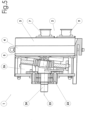
- eine Vorrichtung zum Fördern eines Fluids.
-
Fig. 1 zeigt den Pumpenkopf 2 einer Membranpumpe 1. Die Membranpumpe 1 bildet einen Teil einer Vorrichtung zum Fördern eines Fluids. - Wie der
Fig. 2 zu entnehmen ist, weist der Pumpenkopf 2 eine auch als Kammergehäuse zu bezeichnende Frontplatte 3, eine Ventilplatte 4 sowie eine auch als Membranträger zu bezeichnende Endplatte 5 mit Pumpmembranen 6 auf, die über Pumpelemente mit einer inFig. 2 nicht dargestellten Taumelscheibe verbunden sind. - An der Frontplatte 3 ist ein in dieser Ausführungsform zentraler Einlass 7 vorgesehen, der in eine zentrale Einlasskammer 8 mündet. An der Frontplatte 3 ist ein Auslass 9 vorgesehen, der mit einer in dieser Ausführungsform ringförmigen die Einlasskammer 8 umgebenden Auslasskammer 10 verbunden ist.
- Zwischen der Frontplatte 3 und der Endplatte 5 ist die Ventilplatte 4 angeordnet. Die Ventilplatte 4 weist auf ihrer der Endplatte 5 zugewandten Rückseite 11 vier Pumpkammern 12 auf. Die zu der Endplatte 5 hin offenen Pumpkammern 12 sind jeweils von einer Pumpmembran 6 verschlossen bzw. begrenzt. Die Pumpmembranen 6 sind zwischen der Endplatte 5 und der Ventilplatte 4 angeordnet. Ein in dieser Ausführungsform ringförmiger Wulst 13 der Pumpmembran 6 ist in einer um die Pumpkammer 12 angeordneten Nut 14 der Ventilplatte 4 angeordnet.
- Die Ventilplatte 4 verschließt die Einlasskammer 8 der Frontplatte 3 sowie die Auslasskammer 10 der Frontplatte 3. Die Ventilplatte 4 weist vier Einlassventile 15, die als Schirmventile ausgebildet sind. Über eine dem Einlassventil 15 zugeordnete Einlassöffnung 16 ist die Einlasskammer 8 mit der Pumpkammer 12 verbunden. Die Einlassöffnung 16 ist segmentiert und weist mehrere Einlassöffnungsabschnitte 16a auf.
- Die Ventilplatte 4 dichtet die ringförmige Auslasskammer 10 der Frontplatte 3 ab. Die Ventilplatte 4 ist im Wesentlichen eben ausgebildet und weist acht mit der Auslasskammer 10 korrespondierende Auslassventile 17 auf, die ebenfalls als Schirmventile ausgebildet sind. Die Auslassöffnung 18 des Auslassventils 17 wird durch Auslassöffnungsabschnitte 19 gebildet.
- Für jede Pumpkammer 12 ist ein Einlassventil 15 vorgesehen. Jede Pumpkammer 12 weist zwei Auslassventile 17 auf.
- Die zwei Auslassventile 17 und das Einlassventil 15 bilden in einer Projektion auf eine Projektionsebene quer zur Längsachse L der Pumpkammer 12, die im Wesentlichen parallel zu einer Mittelachse M der Membranpumpe 1 verläuft, ein Dreieck, wie es in
Fig. 3 dargestellt ist. - Der
Fig. 3 ist ferner zu entnehmen, dass benachbarte Auslassventile 17 an der Ventilplatte 4 mit geraden Verbindungslinien verbunden werden können und eine Projektion dieser auf eine Projektionsebene quer zur Längsachse L der Pumpkammer 12 schnittpunktfrei mit den Einlassventilen 15 ist. - Die beiden Auslassventile 17 einer Pumpkammer sind in entgegengesetzten Randbereichen der Pumpkammer 12 angeordnet. Eines der beiden Auslassventile 17 ist in einem oberen Bereich der Pumpkammer 12 angeordnet, während das andere der beiden Auslassventile 17 in einem unteren Bereich der Pumpkammer 12 angeordnet ist. Mittels des oberen der beiden Auslassventile 17 ist eine Entlüftung der Pumpkammer 12 möglich. Mittels des unteren der beiden Auslassventile 17 ist eine Restentleerung möglich. Das Einlassventil 15 einer Pumpkammer 12 ist seitlich versetzt zu einem der beiden Auslassventile 17 angeordnet. Dabei sind die Einlassventile 15 näher zur Mittelachse M der Membranpumpe 1 angeordnet als die Auslassventile 17 der Pumpkammern 12.
- Die beiden Auslassventile 17 einer Pumpkammer 12 sind bezüglich einer Vertikalen, die im Wesentlichen entlang des Schnitts A-A bzw. parallel zu diesem verläuft, versetzt zueinander angeordnet. Das Einlassventil 15 ist außermittig bezogen auf den Querschnitt der Pumpkammer 12 angeordnet.
- Die Auslassventile 17 der Membranpumpe 1 sind kreisförmig um die Mittelachse M der Membranpumpe 1 angeordnet.
- Bezüglich der Ventilplatte 4 liegt eine Rotationsinvarianz um 90° um die Mittelachse M der Membranpumpe 1 vor. Wie der
Fig. 3 ebenfalls zu entnehmen ist, sind die vier Pumpkammern 12 in einem Raster aus Spalten und Zeilen angeordnet, wobei die Pumpkammern 12 über- und nebeneinander angeordnet sind. - Der
Fig. 4 ist ein gegenüber derFig. 3 unterschiedlich ausgestalteter Querschnitt der Pumpkammern 12 für ein weiteres Ausführungsbeispiel der Membranpumpe 1 zu entnehmen. Außer im Querschnitt der Pumpkammern 12 sind die Ausführungsformen sonst gleich und entsprechen einander, so dass es hier keiner Wiederholung bedarf. Der Querschnitt der Pumpkammer 12 im inFig. 4 dargestellten Ausführungsbeispiel weist gerade Abschnitte 20 an der Seitenwandung der Pumpkammer 12 auf, die einen Schnittpunkt mit der Vertikalen und/oder Horizontalen eines Querschnitts der Pumpkammer 12 aufweist. - Die in
Fig. 5 dargestellte Taumelscheibe 21 ist über ein Kugellager 22 mit einem Zapfen 23 einer Antriebswelle 24 verbunden. Der Zapfen 23 ist dabei gegenüber der Längsachse 25 der Antriebswelle 24 geneigt, um eine taumelnde Bewegung der Taumelscheibe 21 zu erzeugen. Die Verbindung zwischen Antriebsachse und Taumelscheibe 21 ist im Bereich einer der Endplatte 5 vorgelagerten Antriebskammer 26 angeordnet. Die Einlasskammer 8 ist gegenüber der Auslasskammer 10 durch eine Dichtung 27, die im Beispiel als Schnurringdichtung ausgebildet ist, abgedichtet. Die äußere Begrenzung der Auslasskammer 10 ist durch eine Dichtung 28, die im Beispiel ebenfalls als Schnurringdichtung ausgebildet ist, abgedichtet. - Durch eine Drehung der Antriebswelle 24 um ihre Längsachse 25 wird die Taumelscheiben 21 aufgrund der Neigung des Zapfens 23 in eine umlaufende Taumelbewegung versetzt, ohne mit der Antriebswelle 24 mit zu rotieren. Durch die Taumelbewegung der Taumelscheibe 21 werden die Pumpmembranen 6 in eine periodisch axiale Pumpbewegung versetzt, durch die in den Pumpkammern 12 wechselweise im Ansaugtakt durch die Bewegung in Richtung der Antriebskammer 26 Unterdruck und im Ausstoßtakt durch eine Bewegung in Richtung der Frontplatte 3 Überdruck erzeugt wird.
- Aufgrund der jeweils stromabseitigen Anordnung des Ventilschirmes des Einlassventils 15 öffnet sich das Einlassventil 15 und schließt sich das entsprechende Auslassventil 17 selbsttätig, wenn in der zugeordneten Pumpkammer 12 Unterdruck herrscht. Bei Überdruck in der Pumpkammer 12 schließt das zugeordnete Einlassventil 15 und öffnet sich das entsprechende Auslassventil 17 selbsttätig. Dadurch wird das Pumpmedium aus der Pumpkammer 12 durch die Auslasskammer 10 zum Auslass 9 hinausgefördert.
Claims (12)
- Membranpumpe (1) mit mindestens einer Pumpkammer (12), wobei die Pumpkammer (12) über ein Einlassventil (15) mit einer Einlasskammer (8) und über zwei Auslassventile (17) mit einer Auslasskammer (10) verbunden ist, wobei das Einlassventil (15) eine durch einen Einlassventilkörper verschließbare Einlassöffnung (16) und jedes Auslassventil (17) eine durch einen jeweiligen Auslassventilkörper verschließbare Auslassöffnung (18) aufweist, wobei die Auslasskammer (10) ringförmig ausgestaltet ist, und wobeidie zwei Auslassventile (17) und das Einlassventil (15) in einer Projektion auf eine Projektionsebene quer zur Längsachse (L) der Pumpkammer (12) ein Dreieck bilden, odereine Projektion von geraden Verbindungslinien, die benachbarte Auslassventile (17) verbinden, auf die Projektionsebene quer zur Längsachse (L) der Pumpkammer (12) schnittpunktfrei mit Einlassventilen (15) ist.
- Membranpumpe (1), nach Anspruch 1, mit zwei Pumpkammern (12), wobei die Pumpkammern (12) jeweils über ein Einlassventil (15) mit einer gemeinsamen Einlasskammer (8) und jeweils über zwei Auslassventile (17) mit einer Auslasskammer (10) verbunden sind, wobei das Einlassventil (15) eine durch einen Einlassventilkörper verschließbare Einlassöffnung (16) und jedes Auslassventil (17) eine durch einen jeweiligen Auslassventilkörper verschließbare Auslassöffnung (18) aufweist.
- Membranpumpe (1) nach einem der Ansprüche 1 oder 2, wobei ein Auslassventil (17) in einem Randbereich der Pumpkammer (12) und ein Auslassventil (17) im entgegengesetzten Randbereich der Pumpkammer (12) angeordnet sind.
- Membranpumpe (1) nach einem der Ansprüche 1 bis 3, wobei das Einlassventil (15) näher zur Mittelachse (M) der Membranpumpe (1) angeordnet ist als die beiden Auslassventile (17).
- Membranpumpe (1) nach einem der Ansprüche 1 bis 4, wobei die beiden für die Pumpkammer (12) vorgesehenen Auslassventile (17) bezüglich einer Vertikalen zueinander versetzt angeordnet sind, wobei die Vertikale quer zur Mittelachse der Membranpumpe und/oder quer zur Längsachse der Pumpkammer verläuft.
- Membranpumpe (1) nach einem der Ansprüche 1 bis 5, wobei die Einlasskammer (8) und Auslasskammer (10) zumindest teilweise in einer Frontplatte (3) ausgebildet sind.
- Membranpumpe (1) nach einem der Ansprüche 1 bis 6, wobei die Pumpkammer (12) ein Einlassventil (15) aufweist, das außermittig im Querschnitt der Pumpkammer (12) angeordnet ist.
- Membranpumpe (1) nach einem der Ansprüche 1 bis 7, wobei mehr als eine Pumpkammer (12) vorgesehen ist, und wobei die Auslassventile (17) kreisförmig bzw. kreissegmentförmig angeordnet sind.
- Membranpumpe (1) nach einem der Ansprüche 1 bis 8, wobei mehr als eine Pumpkammer (12) vorgesehen ist, und die Anordnung des jeweiligen Einlassventils (15) und der jeweiligen beiden Auslassventile (17) der jeweiligen Pumpkammern (12) im Wesentlichen eine Rotationsinvarianz bezüglich eines Winkels unter 360° um die Mittelachse (M) aufweist.
- Membranpumpe (1) nach einem der Ansprüche 1 bis 9, wobei der Querschnitt der Pumpkammer (12) mindestens einen im Wesentlichen geraden Abschnitt an einer Seitenwandung aufweist.
- Membranpumpe (1) nach einem der Ansprüche 1 bis 10, wobei mehrere Pumpkammern (12) vorgesehen sind, die in einem Raster aus Spalten und Zeilen angeordnet sind.
- Vorrichtung zum Fördern von Fluiden mit einer Membranpumpe (1) nach einem der Ansprüche 1 bis 11, wobei ein Pumpenkopf (2) mit einer Antriebskammer (26) und einem Antrieb vorgesehen ist, wobei die Pumpkammer (12) mittels einer Pumpmembran (6) gegenüber der Antriebskammer (26) abgedichtet ist.
Priority Applications (1)
| Application Number | Priority Date | Filing Date | Title |
|---|---|---|---|
| EP25184767.9A EP4644697A1 (de) | 2018-10-11 | 2019-10-09 | Membranpumpe |
Applications Claiming Priority (3)
| Application Number | Priority Date | Filing Date | Title |
|---|---|---|---|
| DE102018008036.7A DE102018008036A1 (de) | 2018-10-11 | 2018-10-11 | Membranpumpe |
| EP19789888.5A EP3864291B1 (de) | 2018-10-11 | 2019-10-09 | Membranpumpe |
| PCT/EP2019/077346 WO2020074576A1 (de) | 2018-10-11 | 2019-10-09 | Membranpumpe |
Related Parent Applications (1)
| Application Number | Title | Priority Date | Filing Date |
|---|---|---|---|
| EP19789888.5A Division EP3864291B1 (de) | 2018-10-11 | 2019-10-09 | Membranpumpe |
Related Child Applications (1)
| Application Number | Title | Priority Date | Filing Date |
|---|---|---|---|
| EP25184767.9A Division EP4644697A1 (de) | 2018-10-11 | 2019-10-09 | Membranpumpe |
Publications (3)
| Publication Number | Publication Date |
|---|---|
| EP4328448A2 EP4328448A2 (de) | 2024-02-28 |
| EP4328448A3 EP4328448A3 (de) | 2024-04-17 |
| EP4328448B1 true EP4328448B1 (de) | 2025-06-25 |
Family
ID=68289921
Family Applications (3)
| Application Number | Title | Priority Date | Filing Date |
|---|---|---|---|
| EP23214388.3A Active EP4328448B1 (de) | 2018-10-11 | 2019-10-09 | Membranpumpe |
| EP25184767.9A Pending EP4644697A1 (de) | 2018-10-11 | 2019-10-09 | Membranpumpe |
| EP19789888.5A Active EP3864291B1 (de) | 2018-10-11 | 2019-10-09 | Membranpumpe |
Family Applications After (2)
| Application Number | Title | Priority Date | Filing Date |
|---|---|---|---|
| EP25184767.9A Pending EP4644697A1 (de) | 2018-10-11 | 2019-10-09 | Membranpumpe |
| EP19789888.5A Active EP3864291B1 (de) | 2018-10-11 | 2019-10-09 | Membranpumpe |
Country Status (6)
| Country | Link |
|---|---|
| US (2) | US12116994B2 (de) |
| EP (3) | EP4328448B1 (de) |
| CN (2) | CN113195895B (de) |
| DE (1) | DE102018008036A1 (de) |
| ES (2) | ES3046816T3 (de) |
| WO (1) | WO2020074576A1 (de) |
Families Citing this family (5)
| Publication number | Priority date | Publication date | Assignee | Title |
|---|---|---|---|---|
| USD923060S1 (en) * | 2018-08-09 | 2021-06-22 | Psg Germany Gmbh | Pump |
| DE102018008037B4 (de) | 2018-10-11 | 2020-09-10 | Psg Germany Gmbh | Spannvorrichtung für eine Vorrichtung zur Förderung von Fluid und Vorrichtung zur Förderung von Fluid |
| US11933286B1 (en) * | 2021-09-02 | 2024-03-19 | Psg Germany Gmbh | Diaphragm pumping |
| WO2025254840A1 (en) * | 2024-06-07 | 2025-12-11 | Wanner Engineering, Inc. | Valve assembly for a diaphragm pump |
| CN119878505A (zh) * | 2025-03-31 | 2025-04-25 | 上海固思流体设备有限公司 | 一种可全排空的四柱塞隔膜泵 |
Family Cites Families (53)
| Publication number | Priority date | Publication date | Assignee | Title |
|---|---|---|---|---|
| US4158530A (en) | 1974-07-01 | 1979-06-19 | Bernstein Robert E | Pumping apparatus comprising two collapsible chambers |
| US4270441A (en) | 1978-10-30 | 1981-06-02 | Wilden Pump & Engineering Co. | Pump diaphragm |
| US4238992A (en) | 1978-10-30 | 1980-12-16 | Wilden Pump & Engineering Co. | Pump diaphragm |
| US4247264A (en) | 1979-04-13 | 1981-01-27 | Wilden Pump & Engineering Co. | Air driven diaphragm pump |
| USD275858S (en) | 1982-06-01 | 1984-10-09 | Wilden Pump & Engineering Co. | Double diaphragm pump |
| US4549467A (en) | 1983-08-03 | 1985-10-29 | Wilden Pump & Engineering Co. | Actuator valve |
| US4570833A (en) * | 1983-08-26 | 1986-02-18 | Vanderjagt John A | Pumping system |
| USD294946S (en) | 1984-08-06 | 1988-03-29 | Wilden Pump & Engineering Co. | Air driven diaphragm pump |
| USD294947S (en) | 1984-08-06 | 1988-03-29 | Wilden Pump & Engineering Co. | Air driven diaphragm pump |
| US5169296A (en) | 1989-03-10 | 1992-12-08 | Wilden James K | Air driven double diaphragm pump |
| US5007803A (en) | 1989-09-28 | 1991-04-16 | Global Pumps, Inc. | Air operated vacuum pump |
| USD331412S (en) | 1989-11-13 | 1992-12-01 | Wilden Pump & Engineering Co. | Air driven diaphragm pump |
| JPH03279684A (ja) * | 1990-03-29 | 1991-12-10 | Aisin Seiki Co Ltd | 圧縮装置 |
| US5147182A (en) | 1990-10-17 | 1992-09-15 | Timmons Robert D | Integrated vacuum pressure system for a bladder pump |
| JP2514774Y2 (ja) * | 1992-09-18 | 1996-10-23 | 日東工器株式会社 | 往復動ポンプ |
| US5378122A (en) | 1993-02-16 | 1995-01-03 | Wilden Pump & Engineering Co. | Air driven diaphragm pump |
| USD382277S (en) | 1996-02-12 | 1997-08-12 | Graco Inc. | Double diaphragm pump |
| US5743170A (en) | 1996-03-27 | 1998-04-28 | Wilden Pump & Engineering Co. | Diaphragm mechanism for an air driven diaphragm pump |
| US5927954A (en) | 1996-05-17 | 1999-07-27 | Wilden Pump & Engineering Co. | Amplified pressure air driven diaphragm pump and pressure relief value therefor |
| US5687633A (en) | 1996-07-09 | 1997-11-18 | Westinghouse Air Brake Company | Insert type member for use in a flexible type pump diaphragm |
| US5634391A (en) | 1996-07-09 | 1997-06-03 | Westinghouse Air Brake Co. | Inert plastic coated flexible type diaphragm for application in a sanitary type pump |
| GB9715741D0 (en) * | 1997-07-26 | 1997-10-01 | Knorr Bremse Systeme | Improvements to gas compressors |
| DE19736703C2 (de) | 1997-08-20 | 1999-07-29 | Mannesmann Ag | Vorrichtung zur Ansteuerung eines Quetschventils |
| US5957670A (en) | 1997-08-26 | 1999-09-28 | Wilden Pump & Engineering Co. | Air driven diaphragm pump |
| US6102363A (en) | 1998-04-20 | 2000-08-15 | Wilden Pump & Engineering Co. | Actuator for reciprocating air driven devices |
| US6257845B1 (en) | 1998-07-14 | 2001-07-10 | Wilden Pump & Engineering Co. | Air driven pumps and components therefor |
| US6152705A (en) | 1998-07-15 | 2000-11-28 | Wilden Pump & Engineering Co. | Air drive pumps and components therefor |
| US6230609B1 (en) | 1999-06-03 | 2001-05-15 | Norton Performance Plastics Corporation | Fluoropolymer diaphragm with integral attachment device |
| USD448778S1 (en) | 1999-10-08 | 2001-10-02 | Smc Kabushiki Kaisha | Diaphragm pump |
| US6343539B1 (en) | 1999-11-10 | 2002-02-05 | Benjamin R. Du | Multiple layer pump diaphragm |
| DE10117531A1 (de) | 2001-04-07 | 2002-10-17 | Quattroflow Fluid Systems Gmbh | Membranpumpe |
| USD499116S1 (en) | 2003-08-07 | 2004-11-30 | Smc Corporation | Diaphragm pump |
| USD498766S1 (en) | 2003-08-07 | 2004-11-23 | Smc Corporation | Diaphragm pump |
| US7063516B2 (en) | 2004-05-04 | 2006-06-20 | Wilden Pump And Engineering Llc | One-way valve |
| US7125229B2 (en) | 2004-05-10 | 2006-10-24 | Wilden Pump And Engineering Llc | Reciprocating air distribution system |
| USD512441S1 (en) | 2004-07-26 | 2005-12-06 | Smc Corporation | Process pump |
| US7517199B2 (en) | 2004-11-17 | 2009-04-14 | Proportion Air Incorporated | Control system for an air operated diaphragm pump |
| DE102005006522B3 (de) | 2005-02-11 | 2006-08-03 | J. Wagner Ag | Vorrichtung zum Fördern von Beschichtungspulver und Verfahren zum Fördern von Pulver mit der Fördervorrichtung |
| JP4668027B2 (ja) | 2005-10-17 | 2011-04-13 | シーケーディ株式会社 | 薬液供給システム |
| US7399168B1 (en) | 2005-12-19 | 2008-07-15 | Wilden Pump And Engineering Llc | Air driven diaphragm pump |
| DE102006048454B3 (de) | 2006-10-11 | 2007-11-15 | Manfred Butsch | Vorrichtung zur Ansteuerung eines Quetschventils |
| DE202006020237U1 (de) | 2006-10-25 | 2008-02-21 | Quattroflow Fluid Systems Gmbh & Co. Kg | Membranpumpe |
| DE102007005313A1 (de) | 2007-02-02 | 2008-08-07 | Itw Gema Ag | Beschichtungspulver-Fördervorrichtung |
| US8282368B2 (en) * | 2007-08-22 | 2012-10-09 | Ford Global Technologies, Llc | Check valve |
| US8157549B2 (en) * | 2008-02-26 | 2012-04-17 | Microjet Technology Co., Ltd. | Multi-channel fluid conveying apparatus |
| DE102008035592B4 (de) * | 2008-07-31 | 2014-10-30 | Almatec Maschinenbau Gmbh | Membranpumpe |
| DE102008037672B4 (de) * | 2008-08-14 | 2016-01-14 | Danfoss A/S | Kolbenverdichter, insbesondere Kältemittelverdichter |
| US9169837B2 (en) * | 2010-12-21 | 2015-10-27 | Pentair Flow Technologies, Llc | Diaphragm pump and motor system and method |
| US20130055887A1 (en) * | 2011-09-02 | 2013-03-07 | Allied Healthcare Products Inc. | Multiple valve head compressor apparatus |
| USD707259S1 (en) | 2013-03-18 | 2014-06-17 | Timmer-Pneumatik Gmbh | Double membrane pump |
| US10082138B2 (en) * | 2014-08-25 | 2018-09-25 | Flowserve Management Company | Valve and valve seat for a diaphragm pump |
| DE102015205651A1 (de) * | 2015-03-27 | 2016-09-29 | Gardner Denver Thomas Gmbh | Hubverdrängerpumpe und dafür einsetzbares Überdruck-Ventil mit einer elastischen Ventilmembran |
| ES2987486T3 (es) * | 2016-11-23 | 2024-11-15 | Psg Germany Gmbh | Bomba de membrana |
-
2018
- 2018-10-11 DE DE102018008036.7A patent/DE102018008036A1/de active Pending
-
2019
- 2019-10-09 CN CN201980066588.1A patent/CN113195895B/zh active Active
- 2019-10-09 WO PCT/EP2019/077346 patent/WO2020074576A1/de not_active Ceased
- 2019-10-09 CN CN202311695858.XA patent/CN117869261A/zh active Pending
- 2019-10-09 ES ES23214388T patent/ES3046816T3/es active Active
- 2019-10-09 EP EP23214388.3A patent/EP4328448B1/de active Active
- 2019-10-09 ES ES19789888T patent/ES2973076T3/es active Active
- 2019-10-09 US US17/281,964 patent/US12116994B2/en active Active
- 2019-10-09 EP EP25184767.9A patent/EP4644697A1/de active Pending
- 2019-10-09 EP EP19789888.5A patent/EP3864291B1/de active Active
-
2024
- 2024-09-12 US US18/883,351 patent/US20250003404A1/en active Pending
Also Published As
| Publication number | Publication date |
|---|---|
| WO2020074576A1 (de) | 2020-04-16 |
| ES2973076T3 (es) | 2024-06-18 |
| CN113195895A (zh) | 2021-07-30 |
| US20210355934A1 (en) | 2021-11-18 |
| EP3864291C0 (de) | 2023-12-06 |
| EP3864291A1 (de) | 2021-08-18 |
| EP4328448A3 (de) | 2024-04-17 |
| ES3046816T3 (en) | 2025-12-02 |
| CN117869261A (zh) | 2024-04-12 |
| US20250003404A1 (en) | 2025-01-02 |
| EP4328448A2 (de) | 2024-02-28 |
| EP3864291B1 (de) | 2023-12-06 |
| US12116994B2 (en) | 2024-10-15 |
| DE102018008036A1 (de) | 2020-04-16 |
| CN113195895B (zh) | 2023-12-29 |
| EP4644697A1 (de) | 2025-11-05 |
Similar Documents
| Publication | Publication Date | Title |
|---|---|---|
| EP4328448B1 (de) | Membranpumpe | |
| EP3327287B1 (de) | Membranpumpe | |
| DE4007932C2 (de) | ||
| EP2761180B1 (de) | Verdrängerpumpe | |
| EP0604740B1 (de) | Membranpumpe | |
| DE102008035592B4 (de) | Membranpumpe | |
| EP0733802B1 (de) | Membranpumpe mit einer Formmembran | |
| DE3718967C2 (de) | Pumpe | |
| DE102007039964B4 (de) | Hochdruck-Doppelmembranpumpe und Membranelement für eine solche Pumpe | |
| DE2502566B2 (de) | Membranpumpe | |
| DE3708327A1 (de) | Einrichtung zum foerdern von fluessigkeit auf zwei ueber spritzduesen zu netzende, mit abstand voneinander angeordnete scheibenbereiche eines kraftfahrzeugs | |
| DE2333380A1 (de) | Hydrostatische pumpen/motoreinheit | |
| DE3042328A1 (de) | Kolbenpumpe | |
| DE10312899A1 (de) | Membranpumpe | |
| EP2057376B1 (de) | Membranpumpe mit zwei membranköpfen und zwei separaten pumpengehäusen | |
| DE102019106370A1 (de) | Ventilanordnungen für eine Membranpumpe, Ventilkörper eines Ventils einer Membranpumpe, Ventilplatte einer Membranpumpe, Membranpumpe, Verfahren zum Betreiben einer Membranpumpe | |
| DE69723144T2 (de) | Doppelmembranpumpe | |
| WO2008080492A1 (de) | Vakuumpumpe mit einem auslassventil | |
| EP1702162A1 (de) | Kolbenkompressor zum verdichten gasförmiger medien in wenigstens zwei arbeitsräumen | |
| DE10210295A1 (de) | Struktur zur Entfernung von Fremdstoffen in einem Fluidkreislauf und ein damit ausgestatteter Kompressor | |
| DE102008031450A1 (de) | Pumpe | |
| DE4034267C2 (de) | Radialkolbenpumpe | |
| DE102015105304A1 (de) | Membranpumpe | |
| EP0929743B1 (de) | Radialkolbenpumpe | |
| DE102017117983A1 (de) | Pumpen-Einheit, damit ausgestattete Lagervorrichtung sowie Verfahren zum Betreiben der Lagervorrichtung |
Legal Events
| Date | Code | Title | Description |
|---|---|---|---|
| PUAI | Public reference made under article 153(3) epc to a published international application that has entered the european phase |
Free format text: ORIGINAL CODE: 0009012 |
|
| STAA | Information on the status of an ep patent application or granted ep patent |
Free format text: STATUS: REQUEST FOR EXAMINATION WAS MADE |
|
| 17P | Request for examination filed |
Effective date: 20231205 |
|
| AC | Divisional application: reference to earlier application |
Ref document number: 3864291 Country of ref document: EP Kind code of ref document: P |
|
| AK | Designated contracting states |
Kind code of ref document: A2 Designated state(s): AL AT BE BG CH CY CZ DE DK EE ES FI FR GB GR HR HU IE IS IT LI LT LU LV MC MK MT NL NO PL PT RO RS SE SI SK SM TR |
|
| REG | Reference to a national code |
Ref country code: DE Ref legal event code: R079 Free format text: PREVIOUS MAIN CLASS: F04B0053100000 Ipc: F04B0043020000 Ref document number: 502019013529 Country of ref document: DE |
|
| PUAL | Search report despatched |
Free format text: ORIGINAL CODE: 0009013 |
|
| AK | Designated contracting states |
Kind code of ref document: A3 Designated state(s): AL AT BE BG CH CY CZ DE DK EE ES FI FR GB GR HR HU IE IS IT LI LT LU LV MC MK MT NL NO PL PT RO RS SE SI SK SM TR |
|
| RIC1 | Information provided on ipc code assigned before grant |
Ipc: F04B 53/10 20060101ALI20240314BHEP Ipc: F04B 43/02 20060101AFI20240314BHEP |
|
| REG | Reference to a national code |
Ref country code: HK Ref legal event code: DE Ref document number: 40108455 Country of ref document: HK |
|
| GRAP | Despatch of communication of intention to grant a patent |
Free format text: ORIGINAL CODE: EPIDOSNIGR1 |
|
| STAA | Information on the status of an ep patent application or granted ep patent |
Free format text: STATUS: GRANT OF PATENT IS INTENDED |
|
| INTG | Intention to grant announced |
Effective date: 20250121 |
|
| GRAS | Grant fee paid |
Free format text: ORIGINAL CODE: EPIDOSNIGR3 |
|
| GRAA | (expected) grant |
Free format text: ORIGINAL CODE: 0009210 |
|
| STAA | Information on the status of an ep patent application or granted ep patent |
Free format text: STATUS: THE PATENT HAS BEEN GRANTED |
|
| AC | Divisional application: reference to earlier application |
Ref document number: 3864291 Country of ref document: EP Kind code of ref document: P |
|
| AK | Designated contracting states |
Kind code of ref document: B1 Designated state(s): AL AT BE BG CH CY CZ DE DK EE ES FI FR GB GR HR HU IE IS IT LI LT LU LV MC MK MT NL NO PL PT RO RS SE SI SK SM TR |
|
| REG | Reference to a national code |
Ref country code: GB Ref legal event code: FG4D Free format text: NOT ENGLISH |
|
| REG | Reference to a national code |
Ref country code: CH Ref legal event code: EP |
|
| REG | Reference to a national code |
Ref country code: CH Ref legal event code: EP |
|
| REG | Reference to a national code |
Ref country code: IE Ref legal event code: FG4D Free format text: LANGUAGE OF EP DOCUMENT: GERMAN |
|
| REG | Reference to a national code |
Ref country code: DE Ref legal event code: R096 Ref document number: 502019013529 Country of ref document: DE |
|
| P01 | Opt-out of the competence of the unified patent court (upc) registered |
Free format text: CASE NUMBER: APP_32253/2025 Effective date: 20250701 |
|
| PG25 | Lapsed in a contracting state [announced via postgrant information from national office to epo] |
Ref country code: FI Free format text: LAPSE BECAUSE OF FAILURE TO SUBMIT A TRANSLATION OF THE DESCRIPTION OR TO PAY THE FEE WITHIN THE PRESCRIBED TIME-LIMIT Effective date: 20250625 |
|
| REG | Reference to a national code |
Ref country code: LT Ref legal event code: MG9D |
|
| PG25 | Lapsed in a contracting state [announced via postgrant information from national office to epo] |
Ref country code: NO Free format text: LAPSE BECAUSE OF FAILURE TO SUBMIT A TRANSLATION OF THE DESCRIPTION OR TO PAY THE FEE WITHIN THE PRESCRIBED TIME-LIMIT Effective date: 20250925 Ref country code: GR Free format text: LAPSE BECAUSE OF FAILURE TO SUBMIT A TRANSLATION OF THE DESCRIPTION OR TO PAY THE FEE WITHIN THE PRESCRIBED TIME-LIMIT Effective date: 20250926 |
|
| PG25 | Lapsed in a contracting state [announced via postgrant information from national office to epo] |
Ref country code: BG Free format text: LAPSE BECAUSE OF FAILURE TO SUBMIT A TRANSLATION OF THE DESCRIPTION OR TO PAY THE FEE WITHIN THE PRESCRIBED TIME-LIMIT Effective date: 20250625 |
|
| PG25 | Lapsed in a contracting state [announced via postgrant information from national office to epo] |
Ref country code: HR Free format text: LAPSE BECAUSE OF FAILURE TO SUBMIT A TRANSLATION OF THE DESCRIPTION OR TO PAY THE FEE WITHIN THE PRESCRIBED TIME-LIMIT Effective date: 20250625 |
|
| PG25 | Lapsed in a contracting state [announced via postgrant information from national office to epo] |
Ref country code: RS Free format text: LAPSE BECAUSE OF FAILURE TO SUBMIT A TRANSLATION OF THE DESCRIPTION OR TO PAY THE FEE WITHIN THE PRESCRIBED TIME-LIMIT Effective date: 20250925 |
|
| PG25 | Lapsed in a contracting state [announced via postgrant information from national office to epo] |
Ref country code: LV Free format text: LAPSE BECAUSE OF FAILURE TO SUBMIT A TRANSLATION OF THE DESCRIPTION OR TO PAY THE FEE WITHIN THE PRESCRIBED TIME-LIMIT Effective date: 20250625 |
|
| REG | Reference to a national code |
Ref country code: NL Ref legal event code: MP Effective date: 20250625 |
|
| REG | Reference to a national code |
Ref country code: CH Ref legal event code: U11 Free format text: ST27 STATUS EVENT CODE: U-0-0-U10-U11 (AS PROVIDED BY THE NATIONAL OFFICE) Effective date: 20251101 |
|
| PG25 | Lapsed in a contracting state [announced via postgrant information from national office to epo] |
Ref country code: NL Free format text: LAPSE BECAUSE OF FAILURE TO SUBMIT A TRANSLATION OF THE DESCRIPTION OR TO PAY THE FEE WITHIN THE PRESCRIBED TIME-LIMIT Effective date: 20250625 |
|
| REG | Reference to a national code |
Ref country code: ES Ref legal event code: FG2A Ref document number: 3046816 Country of ref document: ES Kind code of ref document: T3 Effective date: 20251202 |
|
| PG25 | Lapsed in a contracting state [announced via postgrant information from national office to epo] |
Ref country code: PT Free format text: LAPSE BECAUSE OF FAILURE TO SUBMIT A TRANSLATION OF THE DESCRIPTION OR TO PAY THE FEE WITHIN THE PRESCRIBED TIME-LIMIT Effective date: 20251027 |
|
| PG25 | Lapsed in a contracting state [announced via postgrant information from national office to epo] |
Ref country code: IS Free format text: LAPSE BECAUSE OF FAILURE TO SUBMIT A TRANSLATION OF THE DESCRIPTION OR TO PAY THE FEE WITHIN THE PRESCRIBED TIME-LIMIT Effective date: 20251025 |
|
| PGFP | Annual fee paid to national office [announced via postgrant information from national office to epo] |
Ref country code: DE Payment date: 20251027 Year of fee payment: 7 |
|
| PGFP | Annual fee paid to national office [announced via postgrant information from national office to epo] |
Ref country code: GB Payment date: 20251024 Year of fee payment: 7 |
|
| PG25 | Lapsed in a contracting state [announced via postgrant information from national office to epo] |
Ref country code: SM Free format text: LAPSE BECAUSE OF FAILURE TO SUBMIT A TRANSLATION OF THE DESCRIPTION OR TO PAY THE FEE WITHIN THE PRESCRIBED TIME-LIMIT Effective date: 20250625 |
|
| PGFP | Annual fee paid to national office [announced via postgrant information from national office to epo] |
Ref country code: FR Payment date: 20251028 Year of fee payment: 7 |
|
| PGFP | Annual fee paid to national office [announced via postgrant information from national office to epo] |
Ref country code: CH Payment date: 20251101 Year of fee payment: 7 |
|
| PGFP | Annual fee paid to national office [announced via postgrant information from national office to epo] |
Ref country code: IE Payment date: 20251022 Year of fee payment: 7 Ref country code: CZ Payment date: 20250930 Year of fee payment: 7 |
|
| PG25 | Lapsed in a contracting state [announced via postgrant information from national office to epo] |
Ref country code: PL Free format text: LAPSE BECAUSE OF FAILURE TO SUBMIT A TRANSLATION OF THE DESCRIPTION OR TO PAY THE FEE WITHIN THE PRESCRIBED TIME-LIMIT Effective date: 20250625 |
|
| PG25 | Lapsed in a contracting state [announced via postgrant information from national office to epo] |
Ref country code: EE Free format text: LAPSE BECAUSE OF FAILURE TO SUBMIT A TRANSLATION OF THE DESCRIPTION OR TO PAY THE FEE WITHIN THE PRESCRIBED TIME-LIMIT Effective date: 20250625 |
|
| PG25 | Lapsed in a contracting state [announced via postgrant information from national office to epo] |
Ref country code: SK Free format text: LAPSE BECAUSE OF FAILURE TO SUBMIT A TRANSLATION OF THE DESCRIPTION OR TO PAY THE FEE WITHIN THE PRESCRIBED TIME-LIMIT Effective date: 20250625 |
|
| PGFP | Annual fee paid to national office [announced via postgrant information from national office to epo] |
Ref country code: ES Payment date: 20251104 Year of fee payment: 7 |
|
| PG25 | Lapsed in a contracting state [announced via postgrant information from national office to epo] |
Ref country code: RO Free format text: LAPSE BECAUSE OF FAILURE TO SUBMIT A TRANSLATION OF THE DESCRIPTION OR TO PAY THE FEE WITHIN THE PRESCRIBED TIME-LIMIT Effective date: 20250625 |