EP4327708A1 - Appareil de cuisine portatif avec éjection d'outil ergonomique - Google Patents
Appareil de cuisine portatif avec éjection d'outil ergonomique Download PDFInfo
- Publication number
- EP4327708A1 EP4327708A1 EP22200135.6A EP22200135A EP4327708A1 EP 4327708 A1 EP4327708 A1 EP 4327708A1 EP 22200135 A EP22200135 A EP 22200135A EP 4327708 A1 EP4327708 A1 EP 4327708A1
- Authority
- EP
- European Patent Office
- Prior art keywords
- kitchen appliance
- link member
- food processing
- coupling
- handheld kitchen
- Prior art date
- Legal status (The legal status is an assumption and is not a legal conclusion. Google has not performed a legal analysis and makes no representation as to the accuracy of the status listed.)
- Pending
Links
- 230000008878 coupling Effects 0.000 claims abstract description 109
- 238000010168 coupling process Methods 0.000 claims abstract description 109
- 238000005859 coupling reaction Methods 0.000 claims abstract description 109
- 238000006073 displacement reaction Methods 0.000 description 3
- 238000000034 method Methods 0.000 description 3
- 238000004140 cleaning Methods 0.000 description 2
- 210000003813 thumb Anatomy 0.000 description 2
- 238000010009 beating Methods 0.000 description 1
- 230000001419 dependent effect Effects 0.000 description 1
- 230000000694 effects Effects 0.000 description 1
- 210000003811 finger Anatomy 0.000 description 1
- 238000004898 kneading Methods 0.000 description 1
- 238000000926 separation method Methods 0.000 description 1
Images


Classifications
-
- A—HUMAN NECESSITIES
- A47—FURNITURE; DOMESTIC ARTICLES OR APPLIANCES; COFFEE MILLS; SPICE MILLS; SUCTION CLEANERS IN GENERAL
- A47J—KITCHEN EQUIPMENT; COFFEE MILLS; SPICE MILLS; APPARATUS FOR MAKING BEVERAGES
- A47J43/00—Implements for preparing or holding food, not provided for in other groups of this subclass
- A47J43/04—Machines for domestic use not covered elsewhere, e.g. for grinding, mixing, stirring, kneading, emulsifying, whipping or beating foodstuffs, e.g. power-driven
- A47J43/07—Parts or details, e.g. mixing tools, whipping tools
- A47J43/0705—Parts or details, e.g. mixing tools, whipping tools for machines with tools driven from the upper side
- A47J43/0711—Parts or details, e.g. mixing tools, whipping tools for machines with tools driven from the upper side mixing, whipping or cutting tools
-
- A—HUMAN NECESSITIES
- A47—FURNITURE; DOMESTIC ARTICLES OR APPLIANCES; COFFEE MILLS; SPICE MILLS; SUCTION CLEANERS IN GENERAL
- A47J—KITCHEN EQUIPMENT; COFFEE MILLS; SPICE MILLS; APPARATUS FOR MAKING BEVERAGES
- A47J43/00—Implements for preparing or holding food, not provided for in other groups of this subclass
- A47J43/10—Egg-whisks; Cream-beaters, i.e. hand implements or hand-driven devices
- A47J43/1006—Hand-driven mixing devices with rotating tools, e.g. sticking out from the bottom of the mixing receptacle; with rotating bowls; with an additional function
- A47J43/1031—Hand-driven mixing devices with rotating tools, e.g. sticking out from the bottom of the mixing receptacle; with rotating bowls; with an additional function the mixing device being provided with a grip to be held by one hand, the other hand being used for driving the mixing device
- A47J43/1037—Hand-driven mixing devices with rotating tools, e.g. sticking out from the bottom of the mixing receptacle; with rotating bowls; with an additional function the mixing device being provided with a grip to be held by one hand, the other hand being used for driving the mixing device with two or more mixing tools
- A47J43/1043—Hand-driven mixing devices with rotating tools, e.g. sticking out from the bottom of the mixing receptacle; with rotating bowls; with an additional function the mixing device being provided with a grip to be held by one hand, the other hand being used for driving the mixing device with two or more mixing tools with coaxial tools
-
- A—HUMAN NECESSITIES
- A47—FURNITURE; DOMESTIC ARTICLES OR APPLIANCES; COFFEE MILLS; SPICE MILLS; SUCTION CLEANERS IN GENERAL
- A47J—KITCHEN EQUIPMENT; COFFEE MILLS; SPICE MILLS; APPARATUS FOR MAKING BEVERAGES
- A47J43/00—Implements for preparing or holding food, not provided for in other groups of this subclass
- A47J43/10—Egg-whisks; Cream-beaters, i.e. hand implements or hand-driven devices
- A47J43/1075—Hand-driven mixing devices with reciprocating or oscillating tools
- A47J43/1081—Hand-driven mixing devices with reciprocating or oscillating tools with rectilinearly reciprocating tools
Definitions
- This invention relates to a handheld kitchen appliance having a tool coupling configured to releasably engage at least one food processing tool, a motorized drive system for driving rotation of the at least one engaged food processing tool, and an ejector for urging release of the at least one food processing tool from the tool coupling.
- the food processing tool(s) for example beaters, whisks or dough hooks in the case of food mixers, tend to be detachable from the handheld kitchen appliance's motorized drive system in order to facilitate cleaning of the food processing tool(s) and/or to enable attachment of a different type of food processing tool.
- the handheld kitchen appliance can include a tool release mechanism that urges release of the food processing tool(s) when an ejector button is pressed.
- a tool release mechanism that urges release of the food processing tool(s) when an ejector button is pressed.
- positioning of the ejector button in an ergonomic manner can be challenging, particularly in view of spatial and geometric constraints imposed by other components, such as the motorized drive system, included in the handheld kitchen appliance.
- a handheld kitchen appliance comprising: a tool coupling configured to releasably engage at least one food processing tool; a motorized drive system for driving rotation of the at least one engaged food processing tool; an ejector for urging release of the at least one food processing tool from the tool coupling; an actuator that is movable by a user-applied force; a link member having a first coupling portion for coupling to the actuator, and a second coupling portion spaced apart from the first coupling portion, the link member being pivotally mounted between the first and second coupling portions such that the user-applied force causes a pivoting motion of the link member; and a cam assembly for coupling the ejector and the link member to each other at the second coupling portion, the cam assembly being configured to transform the pivoting motion of the link member to a linear motion of the ejector that urges release of the at least one food processing tool from the tool coupling.
- the pivotably mounted link member can act like a lever in order to transfer the user's movement of the actuator to the ejector via the cam assembly.
- the spacing between the first coupling portion at which the actuator couples, e.g. is attached, to the link member and the second coupling portion at which the cam assembly is coupled to the link member can provide flexibility in terms of where in the handheld kitchen appliance the actuator is positioned.
- the link member can, for example, enable the actuator to be arranged proximal to or at the handheld kitchen appliance's handle, thereby making the handheld kitchen device's food processing tool(s)-ejection functionality more ergonomic.
- the cam assembly further facilitates ejection of the food processing tool(s) by providing flexibility in terms of the direction and/or degree of movement of the actuator that causes the ejector to urge release of the food processing tool(s) from the tool coupling.
- the link member and the cam assembly are configured such that the linear motion of the ejector has a longer travel than the movement of the actuator causing the pivoting motion of the link member.
- a relatively small actuator stroke results in a larger movement of the ejector to urge release of the food processing tool(s).
- the link member and the cam assembly can assist to make ejection of the food processing tool(s) easier for the user to implement via movement of the actuator.
- the link member and the cam assembly may be configured such that the actuator is movable by the user-applied force in the same direction as the resultant linear motion of the ejector that urges release of the at least one food processing tool from the tool coupling.
- the user-applied force being in the same direction as the linear motion of the ejector that urges release of the food processing tool(s) can assist to make implementing the ejection more intuitive for the user.
- the handheld kitchen appliance comprises a handle for permitting a user to grasp the handheld kitchen appliance.
- the first coupling portion may be arranged at or proximal to the handle, with the second coupling portion being correspondingly arranged distal with respect to the handle. This can enable the actuator to be arranged proximal to or at the handle, thereby making the food processing tool(s)-ejection functionality of the handheld kitchen device more ergonomic.
- the placement of the actuator may be such that the user can move the actuator with the same hand that is grasping the handle.
- This may be more ergonomic, and hence more desirable from the consumer's point of view, than, for instance, a design in which the spatial separation of the actuator and the handle is such that two-handed operation is required, with one hand holding the handle and the other hand moving the actuator.
- the handheld kitchen appliance comprises a user-facing exterior surface that faces away from the engaged at least one food processing tool, with at least a portion of the actuator being arranged at or protruding from the user-facing surface and being pushable, by the user-applied force, towards the engaged at least one food processing tool.
- Such arrangement of the actuator at or protruding from the user-facing surface can facilitate ejection of the food processing tool(s) whilst also assisting to avoid unintentional ejection, for example while the food processing tool(s) is or are being rotated by the motorized drive system.
- the link member is pivotably mounted midway between the first coupling portion and the second coupling portion.
- Such mounting of the link member midway between the first coupling portion and the second coupling portion may facilitate control over the length of travel of the linear motion of the ejector relative to the movement of the actuator causing the pivoting motion of the link member.
- the link member is pivotably mounted at a fixed position in the handheld kitchen appliance.
- the only permitted movement of the link member is the pivoting caused by the movement of the actuator.
- the cam assembly comprises a cam gear for engaging the second coupling portion
- the cam gear may be rotatably mounted at a fixed position in the handheld kitchen appliance to define a first axis of rotation, and rotatably coupled to the ejector to define a second axis of rotation extending parallel to the first axis of rotation.
- a first distance between the first axis of rotation and an interface between the second coupling portion and the cam gear may be shorter than a second distance between the first axis of rotation and the second axis of rotation. Making the first distance shorter than the second distance may facilitate a longer length of travel of the linear motion than the movement of the actuator causing the pivoting motion of the link member, in other words a relatively small actuator stroke resulting in a larger movement of the ejector to urge release of the food processing tool(s).
- the link member extends at least partly around the motorized drive system. This may assist to make the design of the handheld kitchen appliance more compact.
- the link member may comprise a ring that extends around the motorized drive system.
- the direction of the linear motion of the ejector that urges release of the at least one food processing tool from the tool coupling is parallel to an axis of rotation of the at least one food processing tool when driven by the motorized drive system.
- the actuator comprises a button portion contactable by the user and a rod portion extending from the button portion to the first coupling portion of the link member.
- the handheld kitchen appliance may comprise the at least one food processing tool.
- the handheld kitchen appliance may be provided, e.g. supplied, to the user separately from the food processing tool(s).
- the handheld kitchen appliance can be any type of handheld kitchen appliance.
- the handheld kitchen appliance being a food mixer, due to the above-described advantages of the link member-cam assembly arrangement in facilitating ejection of the food processing tool(s), e.g. beater(s), whisk(s) or dough hook(s), from the tool coupling of such a food mixer.
- a handheld kitchen appliance comprising a tool coupling configured to releasably engage at least one food processing tool, and a motorized drive system for driving rotation of the at least one engaged food processing tool.
- the handheld kitchen appliance further includes an ejector for urging release of the at least one food processing tool from the tool coupling, and an actuator that is movable by a user-applied force.
- a link member has a first coupling portion for coupling to the actuator, and a second coupling portion spaced apart from the first coupling portion.
- the link member is pivotally mounted between the first and second coupling portions such that the user-applied force causes a pivoting motion of the link member.
- a cam assembly couples the ejector and the link member to each other at the second coupling portion. The cam assembly is configured to transform the pivoting motion of the link member to a linear motion of the ejector that urges release of the at least one food processing tool from the tool coupling.
- FIG. 1 provides an exterior view of a handheld kitchen appliance 100 according to an example.
- FIG. 2 provides an interior view of part of the handheld kitchen appliance 100 shown in FIG. 1 .
- the handheld kitchen appliance 100 comprises a tool coupling 102 configured to releasably engage at least one food processing tool 104A, 104B.
- the handheld kitchen appliance 100 also comprises a motorized drive system 105A, 105B for driving rotation of the food processing tool(s) 104A, 104B when the food processing tool(s) 104A, 104B is or are engaged by the tool coupling 102.
- An ejector 106 is provided for urging release of the at least one food processing tool 104A, 104B from the tool coupling 102, e.g. following food processing using the handheld kitchen appliance 100. Such release of the food processing tool(s) 104A, 104B can facilitate cleaning of the food processing tool(s) 104A, 104B and/or can enable one type of food processing tool(s) 104A, 104B to be exchanged for another type in order to implement a different food processing operation.
- the tool coupling 102 can have any suitable design.
- the tool coupling 102 comprises at least one sleeve, with each of the at least one sleeve being configured to receive and engage a connecting rod of a food processing tool 104A, 104B.
- the engagement between the sleeve and the connecting rod may, for example, be implemented via a snap-fit mechanism, which snap-fit mechanism is releasable by the ejector 106 urging, e.g. pushing, the connecting rod out of the sleeve.
- the connecting rod includes one or more protrusions that are receivable in one or more clamping recesses defined in the sleeve in order to engage the connecting rod received in the sleeve.
- This engagement can enable the food processing tool(s) 104A, 104B to be rotated by the motorized drive system 105A, 105B because the protrusion(s)-clamping recess(es) arrangement keys the rotation of the motorized drive system 105A, 105B to the food processing tool(s) 104A, 104B.
- the engagement between the protrusion(s) and the clamping recess(es) can nonetheless be released by the ejector 106 urging, e.g. pushing, the connecting rod out of the sleeve, and in the process releasing the protrusion(s) from the clamping recess(es).
- the ejector 106 can have any suitable design provided that the ejector 106 is capable of urging release of the at least one food processing tool 104A, 104B from the tool coupling 102.
- the ejector 106 comprises an ejector plate 106A that supports at least one elongate member 106B.
- the elongate member(s) 106B may be arranged to push against the connecting rod(s), e.g. in order to push the connecting rod(s) out of the above-described sleeve(s) included in the tool coupling 102.
- the motorized drive system 105A, 105B preferably comprises a motor 105A and a gear assembly 105B arranged to transfer torque from the motor 105A to the engaged food processing tool(s) 104A, 104B.
- the motor 105A is arranged such that the motor's 105 axis of rotation is aligned or parallel with an ejection axis along which the ejector 106 urges release of the at least one food processing tool 104A, 104B from the tool coupling 102.
- the food processing tool(s) 104A, 104B may be included in the handheld kitchen appliance 100.
- the handheld kitchen appliance 100 may be provided, e.g. supplied, to the user separately from the food processing tool(s) 104A, 104B.
- Any suitable type of food processing tool(s) 104A, 104B can be contemplated.
- the food processing tool(s) 104A, 104B may, for instance, be beater(s), whisk(s) or dough hook(s).
- the tool coupling 102 is configured to releasably engage two food processing tools 104A, 104B so that both food processing tools 104A, 104B can be rotated at the same time by the motorized drive system 105A, 105B.
- the motorized drive system 105A, 105B may be configured to drive rotation of the food processing tools 104A, 104B in opposite directions relative to each other.
- the gear assembly 105B may be configured to drive rotation of the food processing tools 104A, 104B in opposite directions relative to each other.
- the handheld kitchen appliance 100 can be any type of handheld kitchen appliance 100. However, particular mention is made of the handheld kitchen appliance 100 being a food mixer, an example of which is shown in FIGs. 1 and 2 , due to the facilitation of ejection of the food processing tool(s) 104A, 104B, e.g. beater(s), whisk(s) or dough hook(s), from the tool coupling 102, explained herein.
- the food processing tool(s) 104A, 104B e.g. beater(s), whisk(s) or dough hook(s
- the handheld kitchen appliance 100 comprises an actuator 108 that is movable by a user-applied force.
- a link member 110 has a first coupling portion 112 for coupling to the actuator 108, and a second coupling portion 114 spaced apart from the first coupling portion 112 for coupling to the ejector 106.
- the spacing between the first coupling portion 112 at which the actuator 108 couples, e.g. is attached, to the link member 110 and the second coupling portion 114 can provide flexibility in terms of where in the handheld kitchen appliance 100 the actuator 108 is positioned.
- the link member 110 extends at least partly around the motorized drive system 105A, 105B. This may assist to make the design of the handheld kitchen appliance 100 more compact.
- the link member 110 extends at least partly around the motor 105A of the motorized drive system 105A, 105B.
- the link member 110 comprises a ring that extends around the motorized drive system 105A, 105B, for instance a ring that extends around the motor 105A of the motorized drive system 105A, 105B.
- a ring that extends around the motor 105A of the motorized drive system 105A, 105B.
- An example of the latter is shown in FIG. 2 .
- the link member 110 is pivotally mounted between the first and second coupling portions 112, 114. In this way, the user-applied force to move the actuator 108 causes a pivoting motion of the link member 110.
- a cam assembly 116 couples the ejector 106 and the link member 110 to each other at the second coupling portion 114.
- the cam assembly 116 is configured to transform the pivoting motion of the link member 110 caused by the user's movement, e.g. pushing, of the actuator 108 to a linear motion of the ejector 106 that urges release of the at least one food processing tool 104A, 104B from the tool coupling 102.
- the pivotably mounted link member 110 can act like a lever in order to transfer the user's movement of the actuator 108 to the ejector 106 via the cam assembly 116.
- the cam assembly 116 further facilitates ejection of the food processing tool(s) 104A, 104B by providing flexibility in terms of the direction and/or degree of movement of the actuator 108 that causes the ejector 106 to urge release of the food processing tool(s) 104A, 104B from the tool coupling 102.
- the link member 110 and the cam assembly 116 are configured such that the linear motion of the ejector 106 has a longer travel than the movement of the actuator 108 causing the pivoting motion of the link member 110.
- a relatively small actuator 108 stroke results in a larger movement of the ejector 106 to urge release of the food processing tool(s) 104A, 104B.
- the link member 110 and the cam assembly 116 can assist to make ejection of the food processing tool(s) 104A, 104B easier for the user to implement via movement of the actuator 108.
- the link member 110 and the cam assembly 116 may be configured such that the actuator 108 is movable by the user-applied force in the same direction as the resultant linear motion of the ejector 106 that urges release of the at least one food processing tool 104A, 104B from the tool coupling 102.
- the user-applied force being in the same direction as the linear motion of the ejector 106 that urges release of the food processing tool(s) 104A, 104B can assist to make implementing the ejection more intuitive for the user.
- the actuator 108 comprises a button portion 108A contactable by the user and a rod portion 108B extending from the button portion 108A to the first coupling portion 112 of the link member 110.
- the user may, for example, push the button portion 108A with a finger or thumb, when applying the force to cause the ejector 106 to urge release of the food processing tool(s) 104A, 104B from the tool coupling 102.
- the link member 110 can be pivotably mounted in any suitable manner.
- the link member 110 comprises a pair of lever pins 117 that are each locatable in a lever mounting recess defined in an interior portion of the handheld kitchen appliance's main housing 119 in order to enable the link member 110 to pivot when the user moves the actuator 108.
- the link member 110 may be pivotably mounted at a fixed position in the handheld kitchen appliance 100.
- the only permitted movement of the link member 110 is the pivoting caused by the movement of the actuator 108.
- pivotably mounting the link member 110 e.g. pivotably mounting the link member 110 at a fixed position in the handheld kitchen appliance 100
- alternative ways of pivotably mounting the link member 110 e.g. pivotably mounting the link member 110 at a fixed position in the handheld kitchen appliance 100, are conceivable, such as by a pair of mounting recesses being defined in the link member 110, with lever pins protruding from the interior portion of the main housing 119 being locatable in the link member-defined mounting recesses.
- the handheld kitchen appliance 100 comprises a handle 118 for permitting a user to grasp the handheld kitchen appliance 100.
- the handle 118 may, irrespective of how the link member 110 is pivotably mounted, extend from the main housing 119.
- the main housing 119 houses the tool coupling 102, the ejector 106, and at least part of the motorized drive system 105A, 105B, e.g. the motor 105A and/or the gear box assembly 105B.
- the main housing 119 can, in some embodiments, house the motor 105A.
- Arrangement of the motor 105A in the main housing 119, rather than in the handle 118, can mean that the motor's 105A axis of rotation is aligned or parallel with the ejection axis. Whilst this can create a challenge in terms of ergonomic placement of the actuator 108, this can be addressed by the flexibility provided by the above-described link member 110-cam assembly 116 arrangement.
- the first coupling portion 112 is arranged at or proximal to the handle 118, with the second coupling portion 112 being correspondingly arranged distal with respect to the handle 118.
- An example of this is shown in FIG. 2 . This can enable the actuator 108 to be arranged proximal to or at the handle 118, thereby making the food processing tool(s)-ejection functionality of the handheld kitchen device 100 more ergonomic.
- the placement of the actuator 108 is such that the user can move the actuator 108 with the same hand that is grasping the handle 118.
- the handheld kitchen appliance 100 comprises a user-facing exterior surface 120 that faces away from the engaged at least one food processing tool 104A, 104B, with at least a portion of the actuator 108, e.g. the button portion 108A, being arranged at or protruding from the user-facing surface 120 and being pushable, by the user-applied force, towards the engaged at least one food processing tool 104A, 104B.
- the actuator 108 e.g. the button portion 108A
- Such arrangement of the actuator 108 at or protruding from the user-facing surface 120 can facilitate ejection of the food processing tool(s) 104A, 104B whilst also assisting to avoid unintentional ejection, for example while the food processing tool(s) 104A, 104B is or are being rotated by the motorized drive system 105A, 105B.
- the user-facing surface 120 is a surface of the main housing 119.
- the portion of the actuator 108 e.g. the button portion 108A, preferably is at or protrudes from an area of the user-facing surface 120 that is adjacent the handle 118 extending from the main housing 119.
- the user-facing surface 120 may be a surface of the handle 118.
- the cam assembly 116 comprises a cam gear 122 for engaging the second coupling portion 114.
- the second coupling portion 114 may comprise a set of teeth arranged to mesh with a corresponding set of teeth provided on the cam gear 122.
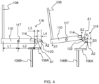
- the cam gear 122 is rotatably mounted at a fixed position in the handheld kitchen appliance 100 to define a first axis of rotation A1, and rotatably coupled to the ejector 106 to define a second axis of rotation A2 extending parallel to the first axis of rotation A1.
- the rotatable mounting of the cam gear 122 at a fixed position in the handheld kitchen appliance 100 can be implemented in any suitable manner.
- the cam gear 122 is rotatably mounted via a gear pin 123 that locates in a gear pin mounting recess 124 defined in an interior portion of the handheld kitchen appliance's main housing 119.
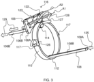
- Operation of the exemplary ejection mechanism is illustrated by the arrows 125, 126, 127, 128 and 129 in FIG. 3 .
- the actuator 108 e.g. the button portion 108A of the actuator 108
- the link member 110 pivots 126 via the lever pin 117, resulting in backwards movement 127 of the second coupling portion 114.
- the cam gear 122 rotates 128 around the gear pin 123 and changes the force direction to push 129 the ejector 106 forwards. The latter urges release of the food processing tool(s) 104A, 104B from the tool coupling 102.
- the direction 129 of the linear motion of the ejector 106 that urges release of the at least one food processing tool 104A, 104B from the tool coupling 102 is preferably parallel to an axis of rotation of the at least one food processing tool 104A, 104B when driven by the motorized drive system 105A, 105B.
- the configuration of the link member 110 and the cam assembly 116 in this example is such that the actuator 108 is movable by the user-applied force in a direction 125 that is the same as a direction 129 of the resultant linear motion of the ejector 106 that urges release of the at least one food processing tool 104A, 104B from the tool coupling 102.
- a first distance L3 between the first axis of rotation A1 and an interface between the second coupling portion 114 and the cam gear 122 is shorter than a second distance L4 between the first axis of rotation A1 and the second axis of rotation A2.
- Making the first distance L3 shorter than the second distance L4 in this manner may facilitate a longer length of travel of the linear motion than the movement of the actuator 108 causing the pivoting motion of the link member 110, in other words a relatively small actuator 108 stroke resulting in a larger movement of the ejector 106 to urge release of the food processing tool(s) 104A, 104B.
- S3 is significantly larger than S1.
- a relatively small actuator stroke can lead to a larger movement of the ejector 106 to urge release of the food processing tool(s) 104A, 104B.
Landscapes
- Engineering & Computer Science (AREA)
- Mechanical Engineering (AREA)
- Food Science & Technology (AREA)
- Food-Manufacturing Devices (AREA)
Priority Applications (1)
| Application Number | Priority Date | Filing Date | Title |
|---|---|---|---|
| PCT/EP2023/073174 WO2024042139A1 (fr) | 2022-08-25 | 2023-08-23 | Appareil de cuisine portatif à éjection d'outil ergonomique |
Applications Claiming Priority (1)
| Application Number | Priority Date | Filing Date | Title |
|---|---|---|---|
| CN2022114953 | 2022-08-25 |
Publications (1)
| Publication Number | Publication Date |
|---|---|
| EP4327708A1 true EP4327708A1 (fr) | 2024-02-28 |
Family
ID=83689025
Family Applications (1)
| Application Number | Title | Priority Date | Filing Date |
|---|---|---|---|
| EP22200135.6A Pending EP4327708A1 (fr) | 2022-08-25 | 2022-10-06 | Appareil de cuisine portatif avec éjection d'outil ergonomique |
Country Status (1)
| Country | Link |
|---|---|
| EP (1) | EP4327708A1 (fr) |
Citations (3)
| Publication number | Priority date | Publication date | Assignee | Title |
|---|---|---|---|---|
| US3544234A (en) * | 1969-06-16 | 1970-12-01 | Scovill Manufacturing Co | Combined speed control-ejector for kitchen mixer |
| US6234663B1 (en) * | 1998-01-23 | 2001-05-22 | Moulinex S.A. | Hand-held household electrical appliance, in particular food mixer |
| EP3323328A1 (fr) * | 2016-11-21 | 2018-05-23 | BSH Hausgeräte GmbH | Mélangeur manuel électrique |
-
2022
- 2022-10-06 EP EP22200135.6A patent/EP4327708A1/fr active Pending
Patent Citations (3)
| Publication number | Priority date | Publication date | Assignee | Title |
|---|---|---|---|---|
| US3544234A (en) * | 1969-06-16 | 1970-12-01 | Scovill Manufacturing Co | Combined speed control-ejector for kitchen mixer |
| US6234663B1 (en) * | 1998-01-23 | 2001-05-22 | Moulinex S.A. | Hand-held household electrical appliance, in particular food mixer |
| EP3323328A1 (fr) * | 2016-11-21 | 2018-05-23 | BSH Hausgeräte GmbH | Mélangeur manuel électrique |
Similar Documents
| Publication | Publication Date | Title |
|---|---|---|
| AU2014218388B2 (en) | Adapter direct drive twist-lock retention mechanism | |
| KR100824686B1 (ko) | 믹서에 부착하기 위한 믹싱 요소 | |
| AU2014259499B2 (en) | Adapter assembly for interconnecting surgical devices and surgical attachments, and surgical systems thereof | |
| EP2881046B1 (fr) | Ensemble adaptateur pour interconnecter des dispositifs chirurgicaux électromécaniques et des unités de chargement chirurgical, systèmes chirurgicaux associés | |
| US7172334B2 (en) | Hand held blender | |
| EP2881045A1 (fr) | Mécanisme de rétention d'un bouton poussoir d'entraînement direct d'adaptateur | |
| EP2465396B1 (fr) | Mélangeur portable doté d'une tête de travail amovible | |
| EP1762136A2 (fr) | Outil motorisé à lames interchangeables et méthode | |
| EP3469973B1 (fr) | Appareil de nettoyage de surface | |
| US20070159917A1 (en) | Pivoting handheld food preparation appliance and associated method | |
| US20220142411A1 (en) | Container for food processing system | |
| CN113425175B (zh) | 用于食品加工设备的搅拌工具及食品加工设备 | |
| WO2013097702A1 (fr) | Robot culinaire | |
| JP2011522658A (ja) | 材料を生地へと混練する混練装置、及び混練ツール | |
| EP4327708A1 (fr) | Appareil de cuisine portatif avec éjection d'outil ergonomique | |
| WO2024042139A1 (fr) | Appareil de cuisine portatif à éjection d'outil ergonomique | |
| CN115005900B (zh) | 微创手术器械组件及微创手术器械 | |
| CN116733955A (zh) | 用于厨房机器的齿轮系统的扭矩输出部件、驱动单元和厨房机器 | |
| EP3960046A1 (fr) | Rotateur, ensemble de rotation, contenant et robot de cuisine | |
| JP2003010670A (ja) | ミキサ要素 | |
| EP4176781A1 (fr) | Composant de verrouillage, tête rotative, ensemble rotatif, accouplement d'arbre, récipient et robot de cuisine | |
| CN112137456B (zh) | 旋转头、旋转组件、容器和食品处理机 | |
| CN220557945U (zh) | 清洁设备及清洁刷组件 | |
| CN112656252B (zh) | 食品处理机 | |
| US20240109042A1 (en) | Mixing and/or scraping assembly for mixing apparatus for food, pharmaceutical or cosmetic products, and mixing apparatus comprising such an assembly |
Legal Events
| Date | Code | Title | Description |
|---|---|---|---|
| PUAI | Public reference made under article 153(3) epc to a published international application that has entered the european phase |
Free format text: ORIGINAL CODE: 0009012 |
|
| STAA | Information on the status of an ep patent application or granted ep patent |
Free format text: STATUS: THE APPLICATION HAS BEEN PUBLISHED |
|
| AK | Designated contracting states |
Kind code of ref document: A1 Designated state(s): AL AT BE BG CH CY CZ DE DK EE ES FI FR GB GR HR HU IE IS IT LI LT LU LV MC ME MK MT NL NO PL PT RO RS SE SI SK SM TR |