EP4325569A1 - Display device comprising semiconductor light-emitting element - Google Patents
Display device comprising semiconductor light-emitting element Download PDFInfo
- Publication number
- EP4325569A1 EP4325569A1 EP22788414.5A EP22788414A EP4325569A1 EP 4325569 A1 EP4325569 A1 EP 4325569A1 EP 22788414 A EP22788414 A EP 22788414A EP 4325569 A1 EP4325569 A1 EP 4325569A1
- Authority
- EP
- European Patent Office
- Prior art keywords
- layer
- disposed
- light emitting
- assembly
- emitting device
- Prior art date
- Legal status (The legal status is an assumption and is not a legal conclusion. Google has not performed a legal analysis and makes no representation as to the accuracy of the status listed.)
- Pending
Links
- 239000004065 semiconductor Substances 0.000 title claims abstract description 59
- 230000031700 light absorption Effects 0.000 claims abstract description 193
- 239000000758 substrate Substances 0.000 claims abstract description 93
- 230000009191 jumping Effects 0.000 claims description 27
- 239000004020 conductor Substances 0.000 claims description 11
- 239000010410 layer Substances 0.000 description 776
- 230000000694 effects Effects 0.000 description 59
- 238000002161 passivation Methods 0.000 description 58
- 102100031102 C-C motif chemokine 4 Human genes 0.000 description 53
- 101000777470 Mus musculus C-C motif chemokine 4 Proteins 0.000 description 53
- 101000908384 Bos taurus Dipeptidyl peptidase 4 Proteins 0.000 description 52
- HEFNNWSXXWATRW-UHFFFAOYSA-N Ibuprofen Chemical compound CC(C)CC1=CC=C(C(C)C(O)=O)C=C1 HEFNNWSXXWATRW-UHFFFAOYSA-N 0.000 description 51
- 102100026620 E3 ubiquitin ligase TRAF3IP2 Human genes 0.000 description 46
- 101710140859 E3 ubiquitin ligase TRAF3IP2 Proteins 0.000 description 46
- 238000000034 method Methods 0.000 description 43
- 230000008569 process Effects 0.000 description 32
- 239000000463 material Substances 0.000 description 25
- 239000003990 capacitor Substances 0.000 description 22
- 230000005684 electric field Effects 0.000 description 22
- 238000004519 manufacturing process Methods 0.000 description 19
- PXHVJJICTQNCMI-UHFFFAOYSA-N Nickel Chemical compound [Ni] PXHVJJICTQNCMI-UHFFFAOYSA-N 0.000 description 17
- 239000002356 single layer Substances 0.000 description 17
- VYPSYNLAJGMNEJ-UHFFFAOYSA-N Silicium dioxide Chemical compound O=[Si]=O VYPSYNLAJGMNEJ-UHFFFAOYSA-N 0.000 description 16
- 229910052814 silicon oxide Inorganic materials 0.000 description 16
- 238000001338 self-assembly Methods 0.000 description 14
- 230000000903 blocking effect Effects 0.000 description 12
- 239000010949 copper Substances 0.000 description 12
- 102100036285 25-hydroxyvitamin D-1 alpha hydroxylase, mitochondrial Human genes 0.000 description 11
- 101000875403 Homo sapiens 25-hydroxyvitamin D-1 alpha hydroxylase, mitochondrial Proteins 0.000 description 11
- 239000011651 chromium Substances 0.000 description 10
- 230000006866 deterioration Effects 0.000 description 9
- 239000012530 fluid Substances 0.000 description 9
- 238000003860 storage Methods 0.000 description 9
- ZOKXTWBITQBERF-UHFFFAOYSA-N Molybdenum Chemical compound [Mo] ZOKXTWBITQBERF-UHFFFAOYSA-N 0.000 description 8
- 229910052581 Si3N4 Inorganic materials 0.000 description 8
- 229910052782 aluminium Inorganic materials 0.000 description 8
- 229910052750 molybdenum Inorganic materials 0.000 description 8
- 239000011733 molybdenum Substances 0.000 description 8
- ZPZCREMGFMRIRR-UHFFFAOYSA-N molybdenum titanium Chemical compound [Ti].[Mo] ZPZCREMGFMRIRR-UHFFFAOYSA-N 0.000 description 8
- 239000011347 resin Substances 0.000 description 8
- 229920005989 resin Polymers 0.000 description 8
- HQVNEWCFYHHQES-UHFFFAOYSA-N silicon nitride Chemical compound N12[Si]34N5[Si]62N3[Si]51N64 HQVNEWCFYHHQES-UHFFFAOYSA-N 0.000 description 8
- 239000010936 titanium Substances 0.000 description 8
- XAGFODPZIPBFFR-UHFFFAOYSA-N aluminium Chemical compound [Al] XAGFODPZIPBFFR-UHFFFAOYSA-N 0.000 description 7
- -1 for example Substances 0.000 description 7
- RYGMFSIKBFXOCR-UHFFFAOYSA-N Copper Chemical compound [Cu] RYGMFSIKBFXOCR-UHFFFAOYSA-N 0.000 description 6
- 229910052802 copper Inorganic materials 0.000 description 6
- 230000007547 defect Effects 0.000 description 6
- 229910052751 metal Inorganic materials 0.000 description 6
- 239000002184 metal Substances 0.000 description 6
- 229910052759 nickel Inorganic materials 0.000 description 6
- 239000011368 organic material Substances 0.000 description 6
- VYZAMTAEIAYCRO-UHFFFAOYSA-N Chromium Chemical compound [Cr] VYZAMTAEIAYCRO-UHFFFAOYSA-N 0.000 description 5
- 229910052804 chromium Inorganic materials 0.000 description 5
- 230000005496 eutectics Effects 0.000 description 5
- 239000012535 impurity Substances 0.000 description 5
- RTAQQCXQSZGOHL-UHFFFAOYSA-N Titanium Chemical compound [Ti] RTAQQCXQSZGOHL-UHFFFAOYSA-N 0.000 description 4
- 229910045601 alloy Inorganic materials 0.000 description 4
- 239000000956 alloy Substances 0.000 description 4
- 230000007797 corrosion Effects 0.000 description 4
- 238000005260 corrosion Methods 0.000 description 4
- 238000004720 dielectrophoresis Methods 0.000 description 4
- 230000005291 magnetic effect Effects 0.000 description 4
- 230000005012 migration Effects 0.000 description 4
- 238000013508 migration Methods 0.000 description 4
- 239000011241 protective layer Substances 0.000 description 4
- 229910052719 titanium Inorganic materials 0.000 description 4
- 229910021417 amorphous silicon Inorganic materials 0.000 description 3
- 239000003086 colorant Substances 0.000 description 3
- 238000005516 engineering process Methods 0.000 description 3
- 239000011159 matrix material Substances 0.000 description 3
- 239000000203 mixture Substances 0.000 description 3
- BASFCYQUMIYNBI-UHFFFAOYSA-N platinum Chemical compound [Pt] BASFCYQUMIYNBI-UHFFFAOYSA-N 0.000 description 3
- 229910021420 polycrystalline silicon Inorganic materials 0.000 description 3
- 229920005591 polysilicon Polymers 0.000 description 3
- JBRZTFJDHDCESZ-UHFFFAOYSA-N AsGa Chemical compound [As]#[Ga] JBRZTFJDHDCESZ-UHFFFAOYSA-N 0.000 description 2
- XEEYBQQBJWHFJM-UHFFFAOYSA-N Iron Chemical compound [Fe] XEEYBQQBJWHFJM-UHFFFAOYSA-N 0.000 description 2
- ATJFFYVFTNAWJD-UHFFFAOYSA-N Tin Chemical compound [Sn] ATJFFYVFTNAWJD-UHFFFAOYSA-N 0.000 description 2
- 230000008901 benefit Effects 0.000 description 2
- 230000003247 decreasing effect Effects 0.000 description 2
- 239000010931 gold Substances 0.000 description 2
- AMGQUBHHOARCQH-UHFFFAOYSA-N indium;oxotin Chemical compound [In].[Sn]=O AMGQUBHHOARCQH-UHFFFAOYSA-N 0.000 description 2
- 239000011777 magnesium Substances 0.000 description 2
- 239000007769 metal material Substances 0.000 description 2
- 238000005728 strengthening Methods 0.000 description 2
- JBQYATWDVHIOAR-UHFFFAOYSA-N tellanylidenegermanium Chemical compound [Te]=[Ge] JBQYATWDVHIOAR-UHFFFAOYSA-N 0.000 description 2
- 229910002704 AlGaN Inorganic materials 0.000 description 1
- 229910017083 AlN Inorganic materials 0.000 description 1
- 229910000980 Aluminium gallium arsenide Inorganic materials 0.000 description 1
- 239000004593 Epoxy Substances 0.000 description 1
- 229910005540 GaP Inorganic materials 0.000 description 1
- 229910001218 Gallium arsenide Inorganic materials 0.000 description 1
- FYYHWMGAXLPEAU-UHFFFAOYSA-N Magnesium Chemical compound [Mg] FYYHWMGAXLPEAU-UHFFFAOYSA-N 0.000 description 1
- XUIMIQQOPSSXEZ-UHFFFAOYSA-N Silicon Chemical compound [Si] XUIMIQQOPSSXEZ-UHFFFAOYSA-N 0.000 description 1
- NIXOWILDQLNWCW-UHFFFAOYSA-N acrylic acid group Chemical group C(C=C)(=O)O NIXOWILDQLNWCW-UHFFFAOYSA-N 0.000 description 1
- 239000000853 adhesive Substances 0.000 description 1
- 230000001070 adhesive effect Effects 0.000 description 1
- AUCDRFABNLOFRE-UHFFFAOYSA-N alumane;indium Chemical compound [AlH3].[In] AUCDRFABNLOFRE-UHFFFAOYSA-N 0.000 description 1
- 229910052790 beryllium Inorganic materials 0.000 description 1
- ATBAMAFKBVZNFJ-UHFFFAOYSA-N beryllium atom Chemical compound [Be] ATBAMAFKBVZNFJ-UHFFFAOYSA-N 0.000 description 1
- 230000008859 change Effects 0.000 description 1
- 238000006243 chemical reaction Methods 0.000 description 1
- 238000005253 cladding Methods 0.000 description 1
- 229910017052 cobalt Inorganic materials 0.000 description 1
- 239000010941 cobalt Substances 0.000 description 1
- GUTLYIVDDKVIGB-UHFFFAOYSA-N cobalt atom Chemical compound [Co] GUTLYIVDDKVIGB-UHFFFAOYSA-N 0.000 description 1
- 150000001875 compounds Chemical class 0.000 description 1
- 230000006835 compression Effects 0.000 description 1
- 238000007906 compression Methods 0.000 description 1
- 238000009826 distribution Methods 0.000 description 1
- 239000003302 ferromagnetic material Substances 0.000 description 1
- 229910052733 gallium Inorganic materials 0.000 description 1
- 229910052732 germanium Inorganic materials 0.000 description 1
- GNPVGFCGXDBREM-UHFFFAOYSA-N germanium atom Chemical compound [Ge] GNPVGFCGXDBREM-UHFFFAOYSA-N 0.000 description 1
- 239000011521 glass Substances 0.000 description 1
- PCHJSUWPFVWCPO-UHFFFAOYSA-N gold Chemical compound [Au] PCHJSUWPFVWCPO-UHFFFAOYSA-N 0.000 description 1
- 229910052737 gold Inorganic materials 0.000 description 1
- 229910052738 indium Inorganic materials 0.000 description 1
- APFVFJFRJDLVQX-UHFFFAOYSA-N indium atom Chemical compound [In] APFVFJFRJDLVQX-UHFFFAOYSA-N 0.000 description 1
- 238000002347 injection Methods 0.000 description 1
- 239000007924 injection Substances 0.000 description 1
- 239000011810 insulating material Substances 0.000 description 1
- 230000002452 interceptive effect Effects 0.000 description 1
- 229910052742 iron Inorganic materials 0.000 description 1
- 239000004973 liquid crystal related substance Substances 0.000 description 1
- 229910052749 magnesium Inorganic materials 0.000 description 1
- 239000000696 magnetic material Substances 0.000 description 1
- 230000035515 penetration Effects 0.000 description 1
- 229910052697 platinum Inorganic materials 0.000 description 1
- 229920000642 polymer Polymers 0.000 description 1
- 238000002360 preparation method Methods 0.000 description 1
- 230000004044 response Effects 0.000 description 1
- 229910052710 silicon Inorganic materials 0.000 description 1
- 239000010703 silicon Substances 0.000 description 1
- 239000010454 slate Substances 0.000 description 1
- 239000000243 solution Substances 0.000 description 1
- 230000000007 visual effect Effects 0.000 description 1
- XLYOFNOQVPJJNP-UHFFFAOYSA-N water Substances O XLYOFNOQVPJJNP-UHFFFAOYSA-N 0.000 description 1
Images


Classifications
-
- H—ELECTRICITY
- H01—ELECTRIC ELEMENTS
- H01L—SEMICONDUCTOR DEVICES NOT COVERED BY CLASS H10
- H01L25/00—Assemblies consisting of a plurality of individual semiconductor or other solid state devices ; Multistep manufacturing processes thereof
- H01L25/03—Assemblies consisting of a plurality of individual semiconductor or other solid state devices ; Multistep manufacturing processes thereof all the devices being of a type provided for in the same subgroup of groups H01L27/00 - H01L33/00, or in a single subclass of H10K, H10N, e.g. assemblies of rectifier diodes
- H01L25/04—Assemblies consisting of a plurality of individual semiconductor or other solid state devices ; Multistep manufacturing processes thereof all the devices being of a type provided for in the same subgroup of groups H01L27/00 - H01L33/00, or in a single subclass of H10K, H10N, e.g. assemblies of rectifier diodes the devices not having separate containers
- H01L25/075—Assemblies consisting of a plurality of individual semiconductor or other solid state devices ; Multistep manufacturing processes thereof all the devices being of a type provided for in the same subgroup of groups H01L27/00 - H01L33/00, or in a single subclass of H10K, H10N, e.g. assemblies of rectifier diodes the devices not having separate containers the devices being of a type provided for in group H01L33/00
- H01L25/0753—Assemblies consisting of a plurality of individual semiconductor or other solid state devices ; Multistep manufacturing processes thereof all the devices being of a type provided for in the same subgroup of groups H01L27/00 - H01L33/00, or in a single subclass of H10K, H10N, e.g. assemblies of rectifier diodes the devices not having separate containers the devices being of a type provided for in group H01L33/00 the devices being arranged next to each other
-
- H—ELECTRICITY
- H01—ELECTRIC ELEMENTS
- H01L—SEMICONDUCTOR DEVICES NOT COVERED BY CLASS H10
- H01L27/00—Devices consisting of a plurality of semiconductor or other solid-state components formed in or on a common substrate
- H01L27/02—Devices consisting of a plurality of semiconductor or other solid-state components formed in or on a common substrate including semiconductor components specially adapted for rectifying, oscillating, amplifying or switching and having at least one potential-jump barrier or surface barrier; including integrated passive circuit elements with at least one potential-jump barrier or surface barrier
- H01L27/12—Devices consisting of a plurality of semiconductor or other solid-state components formed in or on a common substrate including semiconductor components specially adapted for rectifying, oscillating, amplifying or switching and having at least one potential-jump barrier or surface barrier; including integrated passive circuit elements with at least one potential-jump barrier or surface barrier the substrate being other than a semiconductor body, e.g. an insulating body
- H01L27/1214—Devices consisting of a plurality of semiconductor or other solid-state components formed in or on a common substrate including semiconductor components specially adapted for rectifying, oscillating, amplifying or switching and having at least one potential-jump barrier or surface barrier; including integrated passive circuit elements with at least one potential-jump barrier or surface barrier the substrate being other than a semiconductor body, e.g. an insulating body comprising a plurality of TFTs formed on a non-semiconducting substrate, e.g. driving circuits for AMLCDs
- H01L27/124—Devices consisting of a plurality of semiconductor or other solid-state components formed in or on a common substrate including semiconductor components specially adapted for rectifying, oscillating, amplifying or switching and having at least one potential-jump barrier or surface barrier; including integrated passive circuit elements with at least one potential-jump barrier or surface barrier the substrate being other than a semiconductor body, e.g. an insulating body comprising a plurality of TFTs formed on a non-semiconducting substrate, e.g. driving circuits for AMLCDs with a particular composition, shape or layout of the wiring layers specially adapted to the circuit arrangement, e.g. scanning lines in LCD pixel circuits
-
- H—ELECTRICITY
- H01—ELECTRIC ELEMENTS
- H01L—SEMICONDUCTOR DEVICES NOT COVERED BY CLASS H10
- H01L33/00—Semiconductor devices with at least one potential-jump barrier or surface barrier specially adapted for light emission; Processes or apparatus specially adapted for the manufacture or treatment thereof or of parts thereof; Details thereof
- H01L33/005—Processes
- H01L33/0095—Post-treatment of devices, e.g. annealing, recrystallisation or short-circuit elimination
-
- H—ELECTRICITY
- H01—ELECTRIC ELEMENTS
- H01L—SEMICONDUCTOR DEVICES NOT COVERED BY CLASS H10
- H01L33/00—Semiconductor devices with at least one potential-jump barrier or surface barrier specially adapted for light emission; Processes or apparatus specially adapted for the manufacture or treatment thereof or of parts thereof; Details thereof
- H01L33/36—Semiconductor devices with at least one potential-jump barrier or surface barrier specially adapted for light emission; Processes or apparatus specially adapted for the manufacture or treatment thereof or of parts thereof; Details thereof characterised by the electrodes
- H01L33/38—Semiconductor devices with at least one potential-jump barrier or surface barrier specially adapted for light emission; Processes or apparatus specially adapted for the manufacture or treatment thereof or of parts thereof; Details thereof characterised by the electrodes with a particular shape
-
- H—ELECTRICITY
- H01—ELECTRIC ELEMENTS
- H01L—SEMICONDUCTOR DEVICES NOT COVERED BY CLASS H10
- H01L33/00—Semiconductor devices with at least one potential-jump barrier or surface barrier specially adapted for light emission; Processes or apparatus specially adapted for the manufacture or treatment thereof or of parts thereof; Details thereof
- H01L33/36—Semiconductor devices with at least one potential-jump barrier or surface barrier specially adapted for light emission; Processes or apparatus specially adapted for the manufacture or treatment thereof or of parts thereof; Details thereof characterised by the electrodes
- H01L33/40—Materials therefor
- H01L33/42—Transparent materials
-
- H—ELECTRICITY
- H01—ELECTRIC ELEMENTS
- H01L—SEMICONDUCTOR DEVICES NOT COVERED BY CLASS H10
- H01L33/00—Semiconductor devices with at least one potential-jump barrier or surface barrier specially adapted for light emission; Processes or apparatus specially adapted for the manufacture or treatment thereof or of parts thereof; Details thereof
- H01L33/44—Semiconductor devices with at least one potential-jump barrier or surface barrier specially adapted for light emission; Processes or apparatus specially adapted for the manufacture or treatment thereof or of parts thereof; Details thereof characterised by the coatings, e.g. passivation layer or anti-reflective coating
- H01L33/46—Reflective coating, e.g. dielectric Bragg reflector
-
- H—ELECTRICITY
- H01—ELECTRIC ELEMENTS
- H01L—SEMICONDUCTOR DEVICES NOT COVERED BY CLASS H10
- H01L33/00—Semiconductor devices with at least one potential-jump barrier or surface barrier specially adapted for light emission; Processes or apparatus specially adapted for the manufacture or treatment thereof or of parts thereof; Details thereof
- H01L33/48—Semiconductor devices with at least one potential-jump barrier or surface barrier specially adapted for light emission; Processes or apparatus specially adapted for the manufacture or treatment thereof or of parts thereof; Details thereof characterised by the semiconductor body packages
- H01L33/58—Optical field-shaping elements
-
- H—ELECTRICITY
- H01—ELECTRIC ELEMENTS
- H01L—SEMICONDUCTOR DEVICES NOT COVERED BY CLASS H10
- H01L33/00—Semiconductor devices with at least one potential-jump barrier or surface barrier specially adapted for light emission; Processes or apparatus specially adapted for the manufacture or treatment thereof or of parts thereof; Details thereof
- H01L33/48—Semiconductor devices with at least one potential-jump barrier or surface barrier specially adapted for light emission; Processes or apparatus specially adapted for the manufacture or treatment thereof or of parts thereof; Details thereof characterised by the semiconductor body packages
- H01L33/62—Arrangements for conducting electric current to or from the semiconductor body, e.g. lead-frames, wire-bonds or solder balls
-
- H—ELECTRICITY
- H01—ELECTRIC ELEMENTS
- H01L—SEMICONDUCTOR DEVICES NOT COVERED BY CLASS H10
- H01L25/00—Assemblies consisting of a plurality of individual semiconductor or other solid state devices ; Multistep manufacturing processes thereof
- H01L25/16—Assemblies consisting of a plurality of individual semiconductor or other solid state devices ; Multistep manufacturing processes thereof the devices being of types provided for in two or more different main groups of groups H01L27/00 - H01L33/00, or in a single subclass of H10K, H10N, e.g. forming hybrid circuits
- H01L25/167—Assemblies consisting of a plurality of individual semiconductor or other solid state devices ; Multistep manufacturing processes thereof the devices being of types provided for in two or more different main groups of groups H01L27/00 - H01L33/00, or in a single subclass of H10K, H10N, e.g. forming hybrid circuits comprising optoelectronic devices, e.g. LED, photodiodes
-
- H—ELECTRICITY
- H01—ELECTRIC ELEMENTS
- H01L—SEMICONDUCTOR DEVICES NOT COVERED BY CLASS H10
- H01L33/00—Semiconductor devices with at least one potential-jump barrier or surface barrier specially adapted for light emission; Processes or apparatus specially adapted for the manufacture or treatment thereof or of parts thereof; Details thereof
- H01L33/48—Semiconductor devices with at least one potential-jump barrier or surface barrier specially adapted for light emission; Processes or apparatus specially adapted for the manufacture or treatment thereof or of parts thereof; Details thereof characterised by the semiconductor body packages
- H01L33/58—Optical field-shaping elements
- H01L33/60—Reflective elements
Definitions
- the embodiment relates to a display device, and more specifically, to a display device using a semiconductor light emitting device.
- Display devices used in computer monitors, TVs, mobile phones, etc. include Organic Light Emitting Displays that emit light, Liquid Crystal Displays (LCDs) that require a separate light source or micro-LED displays.
- LCDs Liquid Crystal Displays
- a micro-LED display is a display that uses micro-LED, a semiconductor light emitting device with a diameter or cross-sectional area of 100 ⁇ m or less, as a display device.
- micro-LED displays use micro-LED, a semiconductor light emitting device, as a display device, the micro-LED displays have excellent performance in many characteristics such as contrast ratio, response speed, color gamut, viewing angle, brightness, resolution, lifespan, luminous efficiency, or luminance.
- the micro-LED display has the advantage of being able to freely adjust the size and resolution and implement a flexible display because the screen can be separated and combined in a modular manner.
- methods for transferring the semiconductor light emitting device to a substrate include a pick and place process, a laser lift-off method, or a self-assembly method.
- the self-assembly method is a method in which the semiconductor light emitting device finds its assembly position within the fluid on its own, and is an advantageous method for implementing a large-screen display device.
- the technical object of the embodiment is to provide a display device that can prevent reflection of external light using a light absorption layer.
- a technical object of the embodiment is to provide a display device capable of improving viewing angle and side luminance.
- the technical object of the embodiment is to provide a display device that can reduce process costs by simplifying the process of forming the light absorption layer and the planarization layer.
- a technical object of the embodiment is to provide a display device that can improve the stability of the transistor.
- the technical object of the embodiment is to provide a display device that can improve the concentration efficiency of light emitted from a light emitting device.
- the technical object of the embodiment is to provide a display device in which light emitting devices can be stably assembled by improving assembly control of light emitting devices.
- the technical object of the embodiment is to provide a display device with enhanced assembly force for light emitting devices.
- the technical object of the embodiment is to provide a display device that solves the phenomenon of tilting of light emitting devices.
- a display device having a semiconductor light emitting device includes a substrate, first assembly wiring and second assembly wiring alternately arranged on the substrate and spaced apart from each other, and a planarization layer disposed on the first assembly wiring and the second assembly wiring, having an opening hole and a contact hole; a light emitting device disposed in the opening hole of the planarization layer and having a first electrode overlapping the first assembly wiring and the second assembly wiring; and a first light absorption layer arranged to surround the area where the light emitting device disposed, having light absorption characteristics.
- the embodiment includes a transistor disposed below the first assembly wiring and the second assembly wiring, a connection electrode disposed below the planarization layer, disposed on a top of the transistor and electrically connected to the transistor, and further include a pixel electrode that electrically connects the connection electrode and the light emitting device through a contact hole of the planarization layer.
- the first light absorption layer is disposed between the planarization layer, the first assembly wiring, and the second assembly wiring, and may have an opening area and a contact hole that overlap the opening hole and the contact hole of the planarization layer.
- the planarization layer can be arranged to surround top and side surfaces of the first light absorption layer.
- the planarization layer can include a first planarization layer surrounding top surface and side surfaces of the first light absorption layer and a second planarization layer surrounding the top surface and side surfaces of the first planarization layer and covering a portion of the top surface of the light emitting device.
- the embodiment may further include a transparent electrode disposed on the connection electrode to electrically connect the connection electrode and the pixel electrode and transparent electrode being made of a transparent conductive material.
- the first light absorption layer can include a contact area that overlaps the contact hole of the planarization layer.
- the contact hole of the planarization layer and the contact area of the first light absorption layer may expose the transparent electrode disposed on the connection electrode.
- the transparent electrode extends from a top of the connection electrode to the outside of the connection electrode, and the contact hole of the planarization layer and the contact hole of the first light absorption layer can be disposed on the extended portion of the transparent electrode.
- the embodiment may further include at least one of a second light absorption layer disposed on the pixel electrode and a third light absorption layer disposed under the first assembly wiring and the second assembly wiring.
- the substrate can include a display area and a non-display area, and the third light absorption layer can be disposed on at least the entire display area.
- the first assembly wiring may vertically overlap the second assembly wiring, and the second assembly wiring can include an electrode hole in a region that vertically overlaps the first assembly wiring.
- the first light absorption layer is disposed on the planarization layer and may have an opening area that overlaps an opening hole of the planarization layer.
- the embodiment may further include a reflector disposed to surround the light emitting device.
- the planarization layer can include a first planarization layer disposed on the first assembly wiring and the second assembly wiring, and a second planarization layer disposed on the first planarization layer.
- the reflector can be disposed on a side of the first planarization layer.
- the embodiment may further include a third reflector between the second assembly wiring and the light emitting device.
- the second assembly wiring is disposed to extend beyond a center of the assembly hole, and can be disposed on a different plane from the first assembly wiring.
- a display device having a semiconductor light emitting device can include an assembly wiring disposed on a substrate, a light emitting device disposed on the assembly wiring, and a planarization layer disposed on the assembly wiring and surrounding the light emitting device.
- the display device can include a light absorption layer arranged to surround the planarization layer and the light emitting device and having light absorption characteristics.
- the light absorption layer can be disposed between the assembly wiring and the planarization layer.
- the planarization layer can include a first planarization layer disposed to surround side and top surfaces of the light absorption layer and a second planarization layer disposed to surround side and top surfaces of the first planarization layer.
- the planarization layer may further include a first opening hole, which is an area formed by overlapping the opening areas of the light absorption layer and the first planarization layer to overlap the assembly wiring.
- the light emitting device can be disposed in the first opening hole.
- the embodiment includes a connection electrode disposed between the transistor and the planarization layer and electrically connected to the transistor, and a pixel disposed on a top of the connection electrode and the light emitting device and electrically connected to the connection electrode and the light emitting device.
- the embodiment may further include a second opening hole disposed to penetrate the electrode, the light absorption layer, and the first planarization layer and electrically connecting the connection electrode and the pixel electrode.
- the planarization layer can include a first planarization layer disposed to surround side and top surfaces of the light absorption layer and a second planarization layer disposed to surround side and top surfaces of the first planarization layer.
- the embodiment may further include a reflector disposed on a side of the light absorption layer and reflecting light emitted from the light emitting device.
- the assembly wiring can include a conductive layer and a clad layer disposed in contact with the conductive layer at a layer different from the conductive layer and extending to an area outside the conductive layer.
- the light emitting device can be arranged to overlap the extended area of the clad layer.
- the assembly wiring can include a first assembly wiring and a second assembly wiring disposed above the first assembly wiring.
- the embodiment includes a first jumping wire disposed on a different layer from the second assembly wiring and electrically connected to the second assembly wiring, and a second jumping wire disposed below the light emitting device and electrically connected to the light emitting device.
- the second assembly wiring can be electrically connected to the light emitting device through the first jumping wiring and the second jumping wiring.
- the embodiment since the light absorption layer absorbs external light, preventing reflection of external light by metal electrodes, the embodiment has the technical effect of improving visibility of the display device.
- external light reflection due to a contact hole can be minimized by placing a light absorption layer on the pixel electrode.
- the embodiment has the technical effect of improving the viewing angle and lateral brightness of the display device by changing the position of the light absorption layer.
- the height of the light absorption layer lower than the top surface of the light emitting device, light can escape upward.
- the light absorption layer also functions as a planarization layer, so a separate process for forming the light absorption layer is not required, so there is technical effect in that the manufacturing process can be simplified and the process cost can be reduced.
- the embodiment has the technical effect of blocking light emitted from the light emitting device toward the active layer containing an oxide semiconductor material, thereby minimizing deterioration of the active layer by light emitted from the light emitting device.
- the embodiment has the technical effect of concentrating light emitted from the light emitting device and improving the brightness of the display device by arranging the reflector to surround the light emitting device.
- a light path can be changed to the outside of the display device by placing reflectors on the side and bottom of the light emitting device.
- the embodiment has the technical effect of improving assembly control of the light emitting device by connecting the reflector arranged to surround the light emitting device to the assembly wiring.
- the embodiment has the technical effect of strengthening the assembly force for light emitting devices.
- the self-assembly force can be strengthened by arranging the assembly wiring in a vertically symmetrical structure to strengthen the dielectrophoresis force.
- Effects according to the embodiment are not limited to the content exemplified above, and more diverse effects are included in the embodiment.
- Display devices described in this specification include digital TVs, mobile phones, smart phones, laptop computers, digital broadcasting terminals, personal digital assistants (PDAs), portable multimedia players (PMPs), navigation, slate PCs, tablet PCs, ultra-books, or desktop computers, etc.
- PDAs personal digital assistants
- PMPs portable multimedia players
- navigation slate PCs
- tablet PCs tablet PCs
- ultra-books or desktop computers, etc.
- the feature according to the embodiment described in this specification can be applied to a device capable of displaying even if it is a new product type that is developed in the future.
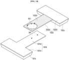
- FIG. 1 is a schematic plan view of a display device according to an embodiment. For convenience of explanation, only the substrate 110 and the plurality of sub-pixels SP among the various elements of the display device 100 are shown in FIG. 1 .
- the display device 100 can include a flexible display manufactured on a thin and flexible substrate.
- Flexible displays can bend or curl like paper while maintaining the characteristics of existing flat displays.
- a unit pixel refers to the minimum unit for implementing one color.
- a unit pixel of a flexible display can be implemented by a light emitting device.
- the light emitting device can be Micro-LED or Nano-LED, but is not limited thereto.
- the substrate 110 can support various elements included in the display device 100 and can be made of an insulating material.
- the substrate 110 can be made of glass or resin.
- the substrate 110 can include polymer or plastic, or can be made of a material with flexibility.
- the substrate 110 can include a display area AA and a non-display area NA.
- the display area AA is an area where a plurality of sub-pixels SP are arranged and an image is displayed.
- Each of the plurality of sub-pixels SP is an individual unit that emits light, and a semiconductor light emitting device LED and a driving circuit are formed in each of the plurality of sub-pixels SP.
- the plurality of sub-pixels SP can include a red sub-pixel, a green sub-pixel, a blue sub-pixel, and/or a white sub-pixel, but are not limited to.
- the description will be made on the assumption that the plurality of sub-pixels SP includes a red sub-pixel, a green sub-pixel, and a blue sub-pixel, but is not limited thereto.
- the non-display area NA is an area where images are not displayed, and is an area where various wiring, driver ICs, etc. for driving the sub-pixels SP arranged in the display area AA are placed.
- various ICs such as gate driver ICs and data driver ICs and driving circuits can be placed in the non-display area NA.
- the non-display area NA can be located on a back of the substrate 110, that is, on the portion without the sub-pixel SP, or can be omitted, and is not limited to what is shown in the drawing.
- the display device 100 of the embodiment can drive the light emitting device using an active matrix AM method or a passive matrix PM method.
- FIGS. 2 and 3 will be referred to together for a more detailed description of the plurality of sub-pixels SP.
- FIG. 2 is a schematic enlarged plan view of a display device according to an embodiment.
- FIG. 3 is a cross-sectional view taken along line III-III' of FIG. 2 .
- the display device 100 includes a plurality of scan wires SL, a plurality of data wires DL, a plurality of high potential power supply wires VDD, and a plurality of assembly wires. 120 and a first transistor TR1, a second transistor TR2, a third transistor TR3, a storage capacitor ST, and a semiconductor light emitting device of each of the plurality of reference lines RL and the plurality of sub-pixels SP.
- Device LED light blocking layer LS, buffer layer 111, gate insulating layer 112, a plurality of passivation layers (113, 115, 116), a lower planarization layer 114, a plurality of planarization layers 118, 119, a connection electrode CE, a transparent electrode TE, a first light absorption layer 160, and a pixel electrode PE.
- a plurality of data wires DL, a first layer VDD1 and a second layer VDD2 of the high-potential power wire VDD, a plurality of reference wires RL, and a plurality of assembly lines 120 extend in the column direction between the plurality of sub-pixels SP, and the third layer VDD3 of the plurality of scan wirings SL and the high potential power supply wiring VDD is connected to the plurality of sub-pixels SP. It may extend in the row direction between.
- a first transistor TR1, a second transistor TR2, a third transistor TR3, and a storage capacitor ST can be disposed in each of the plurality of sub-pixels SP.
- the first layer VDD1 and the light blocking layer LS of the high-potential power line VDD can be disposed on the substrate 110.
- the high-potential power supply line VDD is a line that transmits a high-potential power supply voltage to each of the plurality of sub-pixels SP.
- a plurality of high-potential power supply lines VDD may transmit a high-potential power supply voltage to the second transistor TR2 of each of the plurality of sub-pixels SP.
- the plurality of high-potential power supply wires VDD can be made of a single layer or multiple layers.
- the description will be made on the assumption that the plurality of high-potential power supply wires VDD are made of a plurality of layers.
- the high potential power wiring VDD includes a plurality of first layers VDD1, a plurality of second layers VDD2, and a plurality of third layers VDD3 connecting them.
- the first layer VDD1 may extend in the column direction between each of the plurality of sub-pixels SP.
- a light blocking layer LS can be disposed on each of the plurality of sub-pixels SP on the substrate 110.
- the light blocking layer LS can minimize leakage current by blocking light incident from the lower part of the substrate 110 to the second active layer ACT2 of the second transistor TR2, which will be described later.
- the buffer layer 111 can be disposed on the first layer VDD1 and the light blocking layer LS of the high-potential power line VDD.
- the buffer layer 111 can reduce penetration of moisture or impurities through the substrate 110.
- the buffer layer 111 can be composed of, for example, a single layer or a multiple layer of silicon oxide SiO x or silicon nitride SiN x , but is not limited thereto. However, the buffer layer 111 can be omitted depending on the type of substrate 110 or the type of transistor, but is not limited thereto.
- a plurality of scan wires SL, a plurality of reference wires RL, a plurality of data wires DL, a first transistor TR1, a second transistor TR2, a third transistor TR3, and a storage capacitor ST can be disposed on the buffer layer 111.
- the first transistor TR1 is disposed in each of the plurality of sub-pixels SP.
- the first transistor TR1 includes a first active layer ACT1, a first gate electrode GE1, a first source electrode SE1, and a first drain electrode DE1.
- the first active layer ACT1 can be disposed on the buffer layer 111.
- the first active layer ACT1 can be made of a semiconductor material such as oxide semiconductor, amorphous silicon, or polysilicon, but is not limited thereto.
- the gate insulating layer 112 can be disposed on the first active layer ACT1.
- the gate insulating layer 112 is an insulating layer for insulating the first active layer ACT1 and the first gate electrode GE1, and can be composed of a single layer or multiple layers of silicon oxide SiO x or silicon nitride SiN x , but it is not limited to this.
- the first gate electrode GE1 can be disposed on the gate insulating layer 112.
- the first gate electrode GE1 can be electrically connected to the scan line SL.
- the first gate electrode GE1 can be made of a conductive material, such as copper Cu, aluminum Al, molybdenum Mo, nickel Ni, titanium Ti, chromium Cr, or an alloy thereof, but is not limited to thereto.
- the first passivation layer 113 can be disposed on the first gate electrode GE1. Contact holes can be formed in the first passivation layer 113 to connect the first source electrode SE1 and the first drain electrode DE1 to the first active layer ACT1.
- the first passivation layer 113 is an insulating layer to protect the structure below the first passivation layer 113, and can be composed of a single layer or multiple layers of silicon oxide SiOx or silicon nitride SiNx, but is limited thereto.
- the first source electrode SE1 and the first drain electrode DE1 electrically connected to the first active layer ACT1 can be disposed on the first passivation layer 113.
- the first drain electrode DE1 can be connected to the data line DL, and the first source electrode SE1 can be connected to the second gate electrode GE2 of the second transistor TR2.
- the first source electrode SE1 and the first drain electrode DE1 are made of a conductive material, for example, copper Cu, aluminum Al, molybdenum Mo, nickel Ni, titanium Ti, chromium Cr or an alloy thereof, but is not limited thereto.
- each of the first source electrode SE1 and the first drain electrode DE1 is described as being connected to the second gate electrode GE2 and the data line DL, but depending on the type of transistor, the first source electrode SE1 can be connected to the data line DL, and the first drain electrode DE1 can be connected to the second gate electrode GE2 of the second transistor TR2, but are not limited thereto.
- the first gate electrode GE1 of the first transistor TR1 is connected to the scan line SL and can be turned on or off depending on the scan signal.
- the first transistor TR1 may transfer a data voltage to the second gate electrode GE2 of the second transistor TR2 based on the scan signal, and can be referred to as a switching transistor.
- a plurality of data lines DL and a plurality of reference lines RL along with the first gate electrode GE1 can be disposed on the gate insulating layer 112.
- the plurality of data lines DL and the reference lines RL can be formed of the same material and process as the first gate electrode GE1.
- the plurality of data lines DL are lines that transmit data voltages to each of the plurality of sub-pixels SP.
- the plurality of data lines DL may transmit data voltage to the first transistor TR1 of each of the plurality of sub-pixels SP.
- the plurality of data lines DL include a data line DL that transmits the data voltage to the red sub-pixel SPR, a data line DL that transmits the data voltage to the green sub-pixel SPG, and a blue sub-pixel DL that transmits the data voltage to the red sub-pixel SPR. It can be composed of a data line DL that transmits a data voltage to the pixel SPB.
- the plurality of reference wires RL are wires that transmit a reference voltage to each of the plurality of sub-pixels SP.
- the plurality of reference lines RL may transmit a reference voltage to the third transistor TR3 of each of the plurality of sub-pixels SP.
- a second transistor TR2 can be disposed in each of the plurality of sub-pixels SP.
- the second transistor TR2 includes a second active layer ACT2, a second gate electrode GE2, a second source electrode SE2, and a second drain electrode DE2.
- the second active layer ACT2 can be disposed on the buffer layer 111.
- the second active layer ACT2 can be made of a semiconductor material such as oxide semiconductor, amorphous silicon, or polysilicon, but is not limited thereto.
- the gate insulating layer 112 can be disposed on the second active layer ACT2, and the second gate electrode GE2 can be disposed on the gate insulating layer 112.
- the second gate electrode GE2 can be electrically connected to the first source electrode SE1 of the first transistor TR1.
- the second gate electrode GE2 is made of a conductive material, such as copper Cu, aluminum Al, molybdenum Mo, nickel Ni, titanium Ti, chromium Cr, or an alloy, but is not limited to thereto.
- the first passivation layer 113 can be disposed on the second gate electrode GE2, and the second source electrode SE2 and the second drain electrode DE2 can be disposed on the first passivation layer 113.
- the second source electrode SE2 is electrically connected to the second active layer ACT2.
- the second drain electrode DE2 can be electrically connected to the second active layer ACT2 and at the same time can be electrically connected to the high potential power supply line VDD.
- the second drain electrode DE2 can be disposed between the first layer VDD1 and the second layer VDD2 of the high potential power line VDD and electrically connected to the high potential power line VDD.
- the second transistor TR2 has a second gate electrode GE2 connected to the first source electrode SE1 of the first transistor TR1, and can be turned on by the data voltage transmitted when the first transistor TR1 is turned on. And the turned-on second transistor TR2 can transfer a driving current to the light emitting device LED based on the high-potential power supply voltage from the high-potential power supply line VDD, and thus can be referred to as a driving transistor.
- a third transistor TR3 can be disposed in each of the plurality of sub-pixels SP.
- the third transistor TR3 includes a third active layer ACT3, a third gate electrode GE3, a third source electrode SE3, and a third drain electrode DE3.
- the third active layer ACT3 can be disposed on the buffer layer 111.
- the third active layer ACT3 can be made of a semiconductor material such as an oxide semiconductor, amorphous silicon, or polysilicon, but is not limited thereto.
- the gate insulating layer 112 is disposed on the third active layer ACT3, and the third gate electrode GE3 is disposed on the gate insulating layer 112.
- the third gate electrode GE3 is connected to the scan line SL, and the third transistor TR3 can be turned on or off by the scan signal.
- the third gate electrode GE3 is made of a conductive material, such as copper Cu, aluminum Al, molybdenum Mo, nickel Ni, titanium Ti, chromium Cr, or an alloy thereof, but is not limited to thereto.
- the third gate electrode GE3 and the first gate electrode GE1 are connected to the same scan line SL
- the third gate electrode GE3 can be connected to a different scan line SL from the first gate electrode, but is not limited to this.
- the first passivation layer 113 can be disposed on the third gate electrode GE3, and the third source electrode SE3 and the third drain electrode DE3 can be disposed on the first passivation layer 113.
- the third source electrode SE3 is formed integrally with the second source electrode SE2, is electrically connected to the third active layer ACT3, and is electrically connected to the second source electrode SE2 of the second transistor TR2.
- the third drain electrode DE3 can be electrically connected to the reference wiring RL.
- the third transistor TR3 can be electrically connected to the second source electrode SE2, the reference line RL, and the storage capacitor ST of the second transistor TR2, which is a driving transistor.
- the third transistor TR3 can be referred to as a sensing transistor.
- a storage capacitor ST can be disposed in each of the plurality of sub-pixels SP.
- the storage capacitor ST includes a first capacitor electrode ST1 and a second capacitor electrode ST2.
- the storage capacitor ST is connected between the second gate electrode GE2 and the second source electrode SE2 of the second transistor TR2, and stores the voltage while the light emitting device LED emits light.
- the voltage level of the gate electrode of second transistor TR2 can be maintained constant.
- the first capacitor electrode ST1 can be integrated with the second gate electrode GE2 of the second transistor TR2. Accordingly, the first capacitor electrode ST1 can be electrically connected to the second gate electrode GE2 of the second transistor TR2 and the first source electrode SE1 of the first transistor TR1.
- the second capacitor electrode ST2 can be disposed on the first capacitor electrode ST1 with the first passivation layer 113 interposed therebetween.
- the second capacitor electrode ST2 can be integrated with the second source electrode SE2 of the second transistor TR2 and the third source electrode SE3 of the third transistor TR3. Accordingly, the second capacitor electrode ST2 can be electrically connected to the second transistor TR2 and the third transistor TR3 .
- first source electrode SE1, the first drain electrode DE1, the second source electrode SE2, the second drain electrode (DE2), the third source electrode SE3, the third drain electrode (DE3) and a plurality of scan lines SL are disposed on the first passivation layer 113 along with the second capacitor electrode ST2.
- the plurality of scan wires SL are wires that transmit scan signals to each of the plurality of sub-pixels SP.
- the plurality of scan lines SL may transmit scan signals to the first transistor TR1 of each of the plurality of sub-pixels SP.
- each of the plurality of scan lines SL extends in the row direction and can transmit a scan signal to a plurality of sub-pixels SP arranged in the same row.
- the lower planarization layer 114 includes a plurality of scan lines SL, a plurality of reference lines RL, a plurality of data lines DL, a first transistor TR1, a second transistor TR2, and a third transistor TR2.
- the lower planarization layer 114 can be disposed on the transistor TR3 and the storage capacitor ST.
- the lower planarization layer 114 may planarize the upper part of the substrate 110 on which the plurality of transistors are disposed.
- the lower planarization layer 114 can be composed of a single layer or a double layer, and can be made of, for example, an acryl-based organic material, but is not limited thereto.
- the second passivation layer 115 can be disposed on the lower planarization layer 114.
- the second passivation layer 115 is an insulating layer to protect the structure below the second passivation layer 115 and improve the adhesion of the structure formed on the second passivation layer 115, and is made of silicon oxide SiOx or can be composed of a single layer or multiple layers of silicon nitride SiNx, but is not limited thereto.
- the second layer VDD2 of the high-potential power supply wiring VDD, the plurality of first assembly wirings 121 among the plurality of assembly wiring lines 120, and the connection electrode CE are disposed on the second passivation layer 115.
- the plurality of assembly wirings 120 generate an electric field to align the plurality of light emitting devices LEDs when manufacturing the display device 100, and can be wirings that supply low-potential power supply voltage when the display device 100 is driven. Accordingly, the assembly wiring 120 can be referred to as a low-potential power wiring.
- the plurality of assembly wirings 120 are arranged in a column direction along the plurality of sub-pixels SP arranged on the same line.
- the plurality of assembly wirings 120 can be arranged to overlap the plurality of sub-pixels SP arranged in the same column.
- one first assembly wiring 121 and a second assembly wiring 122 can be disposed in the red sub-pixel SPR arranged in the same column, and one first assembly wiring 121 and one second assembly wiring 122 can be disposed in the green sub-pixel SPG. And one first assembly wiring 121 and a second assembly wiring 122 can be disposed in the blue sub-pixel SPB.
- the plurality of assembly wiring lines 120 includes a plurality of first assembly wiring lines 121 and a plurality of second assembly wiring lines 122.
- a plurality of transistors can be disposed below the plurality of first assembly wirings 121 and the plurality of second assembly wirings 122, and when the display device 100 is driven, a low-potential voltage can be applied to the plurality of first assembly wirings 121 and the plurality of second assembly wirings 122 in alternating current.
- the plurality of first assembly wires 121 and the plurality of second assembly wires 122 can be alternately arranged. Additionally, in each of the plurality of sub-pixels SP, one first assembly wiring 121 and one second assembly wiring 122 can be disposed adjacent to each other.
- the plurality of first assembly wirings 121 and the plurality of second assembly wirings 122 can be made of a conductive material, for example, copper Cu and chromium Cr, but are not limited thereto.
- the second layer VDD2 of the high-potential power supply line VDD can be disposed on the second passivation layer 115.
- the second layer VDD2 is located between each of the plurality of sub-pixels SP in the column direction and extends to and may overlap with the first layer VDD1.
- the first layer VDD1 and the second layer VDD2 can be electrically connected through a contact hole formed in the insulating layers formed between the first layer VDD1 and the second layer VDD2.
- the second layer VDD2 can be formed of the same material and process as the first assembly wiring 121, but is not limited thereto.
- a connection electrode CE can be disposed in each of the plurality of sub-pixels SP.
- the plurality of connection electrodes CE can be disposed on top of the second plurality of transistors TR2 and can be electrically connected to the second plurality of transistors TR2.
- the connection electrode CE can be electrically connected to the second capacitor electrode ST2 and the second source electrode SE2 of the second transistor TR2 through a contact hole formed in the second passivation layer 115.
- the connection electrode CE is an electrode for electrically connecting the light emitting device LED and the second transistor TR2, which is a driving transistor, and is made of the same material on the same layer as the first assembly wiring 121.
- the transparent electrode TE can be disposed on the connection electrode CE.
- the transparent electrode TE can be disposed on the connection electrode CE to electrically connect the connection electrode CE and the light emitting device LED.
- the transparent electrode TE can be arranged to extend from a top of the connection electrode CE to the outside of the connection electrode CE. That is, a part of the transparent electrode TE may overlap the connection electrode CE, and another part of the transparent electrode TE can be extended to a position that does not overlap the connection electrode CE.
- the transparent electrode TE can be formed of a transparent conductive material.
- the transparent electrode TE can be formed of, for example, Indium Tin Oxide ITO, but is not limited thereto.
- the third passivation layer 116 is disposed on the second layer VDD2, the first assembly wiring 121, the connection electrode CE, and the transparent electrode TE.
- the third passivation layer 116 is an insulating layer to protect the structure below the third passivation layer 116, and can be composed of a single layer or multiple layers of silicon oxide SiOx or silicon nitride SiNx, but is limited thereto.
- the third passivation layer 116 may function as an insulating layer to prevent short circuit defects due to migration between the first assembly wiring 121 and the second assembly wiring 122 when manufacturing the display device 100. This will be described later with reference to FIGS. 4A to 4F .
- the plurality of second assembly wiring lines 122 can be disposed on the third passivation layer 116.
- Each of the plurality of second assembly wirings 122 is disposed in a plurality of sub-pixels SP arranged on the same line as described above, and the plurality of first assembly wirings 121 and the plurality of second assembly wirings 122 can be placed spaced apart from each other.
- Each of the plurality of second assembly wirings 122 includes a second conductive layer 122a and a second clad layer 122b.
- the second conductive layer 122a can be disposed on the third passivation layer 116.
- the second clad layer 122b can be electrically connected to the second conductive layer 122a.
- the second clad layer 122b can be disposed to cover the top and side surfaces of the second conductive layer 122a.
- the second conductive layer 122a may have a thickness greater than that of the second clad layer 122b.
- the second clad layer 122b is made of a material that is more resistant to corrosion than the second conductive layer 122a, so that there is a technical effect that can minimize short circuit defects occurrence due to migration between the first assembly wiring 121 and the second assembly wiring 122 when manufacturing the display device 100.
- the second clad layer 122b can be made of molybdenum Mo, molybdenum titanium MoTi, etc., but is not limited thereto.
- the first light absorption layer 160 can be disposed on the plurality of first assembly wiring lines 121 and the plurality of second assembly wiring lines 122. Specifically, the first light absorption layer 160 can be disposed on the third passivation layer 116 and the plurality of second assembly lines 122.
- the first light absorption layer 160 is arranged to surround the area where the light emitting device LED is placed, and has the technical effect of flattening the area where the light emitting device LED is placed. Accordingly, the first light absorption layer 160 may also function as a planarization layer.
- the first light absorption layer 160 includes an opening area 118a and a contact hole 160b, and a light emitting device LED can be disposed within the opening area 118a of the first light absorption layer 160.
- the contact hole 160b of the first light absorption layer 160 exposes an extended portion of the transparent electrode TE extending from the top of the connection electrode CE to the outside of the connection electrode CE. Accordingly, the light emitting device LED and the transistor can be electrically connected by connecting the exposed portion of the pixel electrode PE, which will be described later, with the transparent electrode TE.
- the first light absorption layer 160 can reduce color mixing between the plurality of sub-pixels SP and reduce external light reflection.
- the first light absorption layer 160 allows light emitted from the light emitting device LED to pass through the first active layer ACT1 of the first transistor TR1, the second active layer ACT2 of the second transistor TR2, and there is a technical effect of blocking incident light on the third active layer ACT3 of the third transistor TR3.
- the first active layer ACT1, the second active layer ACT2, and the third active layer ACT3 are made of an oxide semiconductor, the first active layer ACT1, the second active layer ACT2, and the third active layer ACT3 can be deteriorated by light incident on the first active layer ACT1, the second active layer ACT2, and the third active layer ACT3. Accordingly, the first light absorption layer 160 is arranged to surround the area where the light emitting device LED is disposed, so that the light emitted from the light emitting device LED flows into the first active layer ACT1 and the second active layer ACT2. So there is a technical effect of blocking incident light on the third active layer ACT3.
- the top surface of the first light absorption layer 160 is located lower than the top surface of the plurality of light emitting devices LEDs. Accordingly, the viewing angle of the display device 100 can be improved.
- the first light absorption layer ACT3 is arranged to reduce color mixing between the plurality of sub-pixels SP and minimize external light reflection, but may also absorb light emitted from the light emitting device LED.
- the top surface of the first light absorption layer 160 is located higher than the top surface of the light emitting device LED, light emitted toward the top of the light emitting device LED can be absorbed from the first light absorption layer 160. Accordingly, the upper surface of the first light absorption layer 160 can be disposed at a lower position than the upper surface of the light emitting device LED, so there is a technical effect in that the lateral luminance with respect to the light emitted from the light emitting device LED can be improved, and the viewing angle of the display device 100 is improved.
- the first light absorption layer 160 can be made of a material having light absorption properties.
- the first light absorption layer 160 can be made of an opaque material, for example, black resin, but is not limited thereto.
- the first planarization layer 118 can be disposed on the first light absorption layer 160. Specifically, the first planarization layer 118 is disposed on the plurality of first assembly wirings 121, the plurality of second assembly wirings 122, the connection electrode CE, and the first light absorption layer 160, so the first planarization layer 118 can be arranged to surround the top and side surfaces of the light absorption layer 160. Accordingly, the first light absorption layer 160 can be disposed between the first planarization layer 118 and the plurality of first assembly wirings 121 and the plurality of second assembly wirings 122.
- the first planarization layer 118 can be composed of a single layer or a double layer, and can be made of, for example, an acryl-based organic material, but is not limited thereto.
- the first planarization layer 118 has a plurality of opening holes 118a on which each of the plurality of light emitting devices LED is seated, and a plurality of contact holes exposing each of the plurality of transparent electrodes TE on the plurality of connection electrodes CE.
- the opening hole 118a of the first planarization layer 118 overlaps the opening area 160a of the first light absorption layer 160, and the contact hole 118b of the first planarization layer 118 can be arranged to overlap the contact hole 160b of the first light absorption layer 160.
- the plurality of opening holes 118a are parts into which a plurality of light emitting devices LEDs are inserted, and may also be referred to as pockets.
- the plurality of opening holes 118a can be formed to overlap the plurality of assembly wires 120.
- one opening hole 118a may overlap the first assembly wiring 121 and the second assembly wiring 122 disposed adjacent to each other in one sub-pixel SP.
- the second clad layer 122b of the plurality of second assembly wirings 122 can be exposed through the opening hole 118a.
- the third passivation layer 116 covers all of the first assembly wiring 121 in the opening hole 118a, the first assembly wiring 121 overlaps the opening hole 118a but is not exposed from the opening hole 118a.
- a plurality of contact holes 118b are disposed in the plurality of sub-pixels SP.
- the plurality of contact holes 118b expose the extended portion of the transparent electrode TE on the connection electrode CE of each of the plurality of sub-pixels SP.
- the transparent electrode TE under the first planarization layer 118 is exposed through the plurality of contact holes 118b, and the connection electrode CE connected to the transparent electrode TE can be electrically connected to the light emitting device LED. Accordingly, the connection electrode CE and the transparent electrode TE can transmit the driving current from the second transistor TR2 to the light emitting device LED.
- the first light absorption layer 160, the first planarization layer 118, and the third passivation layer 116 may each have a contact hole in the area overlapping the contact hole 118b, and thus the connection electrode CE can be exposed from the first light absorption layer 160, the first planarization layer 118, and the third passivation layer 116.
- a plurality of light emitting devices LEDs can be disposed in a plurality of opening holes 118a.
- the plurality of light emitting devices LEDs are light emitting devices LEDs that emit light by electric current.
- the plurality of light emitting devices LEDs can include light emitting devices LEDs that emit red light, green light, blue light, etc., and a combination of these can produce light of various colors, including white.
- the light emitting device LED can be a light emitting diode LED or a micro-LED, but is not limited thereto.
- a plurality of light emitting devices LEDs include the red light emitting device 130 arranged in the red sub-pixel SPR, the green light emitting device 140 located in the green sub-pixel SPG, and blue light emitting device 150 arranged in the blue sub-pixel SPB.
- the description will be made assuming that the blue light emitting device 150.
- the plurality of light emitting devices LEDs are composed of light emitting devices LEDs that emit light of the same color, and a separate light conversion member is used to convert the light from the plurality of light emitting devices LEDs into light of different colors.
- images in various colors can be displayed, but are not limited to thereto.
- the plurality of light emitting devices LEDs include a red light emitting device 130 disposed in the red sub-pixel SPR, a green light emitting device 140 disposed in the green sub-pixel SPG, and a blue light emitting device 150 disposed in the blue sub-pixel SPB.
- Each of the red light emitting device 130, the green light emitting device 140, and the blue light emitting device 150 can include a first semiconductor layer, a second semiconductor layer, a first electrode, and a second electrode in common.
- the red light emitting device 130 includes a light emitting layer that emits red light
- the green light emitting device 140 includes a light emitting layer that emits green light
- the blue light emitting device 150 includes a light emitting layer that emits blue light.
- the red light emitting device 130 disposed in the red sub-pixel SPR has a second semiconductor layer 133 disposed on the first semiconductor layer 131.
- the first semiconductor layer 131 and the second semiconductor layer 133 can be layers formed by doping n-type and p-type impurities into a specific material.
- the first semiconductor layer 131 and the second semiconductor layer 133 can include an AlInGaP-based semiconductor layer, for example, indium aluminum phosphide (InAlP), gallium arsenide (GaAs), etc. It can be a layer doped with type p-type or n-type impurities.
- the p-type impurities can be magnesium (Mg), zinc (Zn), beryllium (Be), etc.
- the n-type impurities can be silicon (Si), germanium (Ge), tin (Sn), etc., but are not limited thereto.
- a light emitting layer 132 that emits red light is disposed between the first semiconductor layer 131 and the second semiconductor layer 133.
- the light emitting layer 132 may emit light by receiving holes and electrons from the first semiconductor layer 131 and the second semiconductor layer 133.
- the light emitting layer 132 may have a single-layer or multi-quantum well (MQW) structure.
- the light emitting layer 132 converts injected electrical energy into light with a specific wavelength within the range of about 570 nm to about 630 nm.
- the change in specific wavelength is determined by the size of the band gap of the light emitting diode.
- the band gap size can be adjusted by changing the composition ratio of Al and Ga. For example, as the composition ratio of Al increases, the wavelength becomes shorter.
- the first electrode 134 is disposed on the lower surface of the first semiconductor layer 131, and the second electrode 135 is disposed on the upper surface of the second semiconductor layer 133.
- the first electrode 134 is an electrode bonded to the second assembly wiring 122 exposed in the opening hole 118a, and the second electrode 135 is an electrode that connects electrically a pixel electrode PE which will be described later and the second semiconductor layer 133.
- the first electrode 134 and the second electrode 135 can be formed of a conductive material.
- the first electrode 134 can be disposed in the plurality of opening holes 118a to overlap the plurality of first assembly wirings 121 and the plurality of second assembly wirings 122. At this time, in order to bond the first electrode 134 to the second assembly wiring 122, the first electrode 134 can be made of a eutectic metal.
- the first electrode 134 is made of tin (Sn), indium (In), zinc (Zn), lead (Pb), nickel (Ni), gold (Au), platinum (Pt), and copper (Cu), but is not limited thereto.
- both the green light emitting device 140 and the blue light emitting device 150 can be formed with the same or similar structure as the red light emitting device 130.
- the green light emitting device 140 includes a first electrode, a first semiconductor layer on the first electrode, a green light emitting layer on the first semiconductor layer, a second semiconductor layer on the green light emitting layer, and a second electrode on the second semiconductor layer.
- the blue light emitting device can include a structure in which a first electrode, a first semiconductor layer, a blue light emitting layer, a second semiconductor layer, and a second electrode are sequentially stacked.
- the green light emitting device 140 and the blue light emitting device 150 can be formed of a compound selected from the group consisting of GaN, AlGaN, InGaN, AlInGaN, GaP, AlN, GaAs, AlGaAs, InP, and mixtures thereof, but is not limited to thereto.
- an insulating layer surrounding a portion of each of the plurality of light emitting devices LEDs can be disposed.
- the insulating layer may cover at least a side surface of the plurality of light emitting devices LEDs among the outer surfaces of the light emitting devices LEDs.
- An insulating layer is formed on the light emitting device LED to protect the light emitting device LED, so electrical short circuit can be prevented when forming the first electrode 134 and the second electrode 135, the first semiconductor layer 131 and the second semiconductor layer 133.
- the second planarization layer 119 can be disposed on the plurality of light emitting devices LEDs.
- the second planarization layer 119 can be arranged to surround the top and side surfaces of the first planarization layer 118 and cover a portion of the top surfaces of the plurality of light emitting devices LEDs.
- the second planarization layer 119 has a plurality of light emitting devices.
- the second planarization layer 119 can be disposed on the plurality of light emitting devices LEDs.
- the second planarization layer 119 can be arranged to surround the top and side surfaces of the first planarization layer 118 and cover a portion of the top surfaces of the plurality of light emitting devices LEDs.
- the second planarization layer 119 can planarize the upper part of the substrate 110 on which the plurality of light emitting devices LEDs are disposed, and the plurality of light emitting devices LEDs formed at the opening hole 118a by the second planarization layer 119 can be stably fixed.
- the second planarization layer 119 can be composed of a single layer or a double layer, and can be made of, for example, an acryl-based organic material, but is not limited thereto.
- the pixel electrode PE can be disposed on the second planarization layer 119.
- the pixel electrode PE is an electrode for electrically connecting a plurality of light emitting devices LED and the connection electrode CE.
- the pixel electrode PE can be electrically connected to the light emitting device LED of the opening hole 118a and the transparent electrode TE of the contact hole 118b through a contact hole formed in the second planarization layer 119. Accordingly, the second electrode 135, the transparent electrode TE, the connection electrode CE, and the second transistor TR2 of the light emitting device LED can be electrically connected through the pixel electrode PE.
- the third layer VDD3 of the high potential power line VDD can be disposed on the second planarization layer 119.
- the third layer VDD3 may electrically connect the first layer VDD1 and the second layer VDD2 arranged in different rows.
- the third layer VDD3 extends in the row direction between the plurality of sub-pixels SP, and connects the plurality of second layers VDD2 of the high potential power supply line VDD extending in the column direction to each other electrically connect with.
- the plurality of high-potential power wiring lines VDD are connected in a mesh form through the third layer VDD3, the voltage drop phenomenon can be reduced.
- the protective layer PTL can be disposed on the pixel electrode PE and the second planarization layer 119.
- the protective layer PTL is a layer to protect the structure below the protective layer PTL and can be composed of a single layer or multiple layers of translucent epoxy, silicon oxide (SiOx), or silicon nitride (SiNx), but is not limited thereto.
- the plurality of first assembly wirings 121 are spaced apart from the plurality of light emitting devices LEDs, and only the plurality of second assembly wirings 122 can contact the plurality of light emitting devices LEDs. This is to prevent defects that occur when a plurality of light emitting devices LEDs come into contact with both the first assembly wiring 121 and the plurality of second assembly wiring 122 during the manufacturing process of the display device 100.
- a third passivation layer 116 can be formed on the first assembly wiring 121, and a plurality of light emitting devices LEDs can be contacted only to the plurality of second assembly wirings 122.
- FIGS. 4A to 4F are process drawings for explaining a manufacturing method of a display device according to an embodiment.
- FIGS. 4A and 4B are process drawings for explaining a process of self-assembling a plurality of light emitting devices LEDs into the opening hole 118a.
- FIG. 4C is a schematic plan view of the mother substrate 10 used for self-assembly of a plurality of light emitting devices LEDs.
- FIG. 4D is a drawing schematically showing the electrical connection relationship between the plurality of assembly wires 120 and the assembly pad PD.
- FIG. 4E is a schematic plan view of a plurality of substrates 110 formed by scribing the mother substrate 10 after self-assembly of a plurality of light emitting devices LEDs is completed.
- FIG. 4F is a schematic cross-sectional view of area X in FIG. 4E .
- a light emitting device LED is introduced into the chamber CB filled with the fluid WT.
- the fluid WT can include water, etc., and the chamber CB filled with the fluid WT may have an open top.
- the mother substrate 10 can be placed on the chamber CB filled with light emitting devices LED.
- the mother substrate 10 is a substrate composed of a plurality of substrates 110 forming the display device 100, and when self-assembling a plurality of light emitting devices LEDs, a plurality of assembly wirings 120 and a first light absorption layer 160 are formed and the mother substrate 10 formed up to the first planarization layer 118 can be used.
- the mother substrate 10 formed with the first assembly wiring 121, the second assembly wiring 122, the first light absorption layer 160, and the first planarization layer 118 is placed on the chamber CB, and put into the chamber CB. At this time, the mother substrate 10 can be positioned so that the opening hole 118a and the fluid WT face each other.
- the magnet MG can be placed on the mother substrate 10.
- Light emitting devices LEDs that sink or float on the bottom of the chamber CB may move toward the mother substrate 10 by the magnetic force of the magnet MG.
- the light emitting device LED can include a magnetic material to move by a magnetic field.
- the first electrode 134 or the second electrode 135 of the light emitting device LED can include a ferromagnetic material such as iron, cobalt, or nickel.
- the light emitting device LED moved toward the first light absorption layer 160 and the first planarization layer 118 by the magnet MG is connected to the first assembly wiring 121 and the second assembly wiring 122. So, the light emitting device LED can be self-assembled in the opening hole 118a by the formed electric field.
- An alternating voltage can be applied to the plurality of first assembly wirings 121 and the plurality of second assembly wirings 122 to generate an electric field. Due to this electric field, the light emitting device LED is dielectrically polarized and may have polarity. And a dielectric polarized light emitting device LED can be moved or fixed in a specific direction by dielectrophoresis DEP, that is, an electric field. Therefore, a plurality of light emitting devices LEDs can be fixed within the opening hole 118a using dielectrophoresis.
- the mother substrate 10 is flipped 180° with the light emitting device LED fixed in the opening hole 118a using the electric fields of the plurality of first assembly wirings 121 and the plurality of second assembly wirings 122.
- the mother substrate 10 can be turned over while voltage is applied to the plurality of first assembly wirings 121 and the plurality of second assembly wirings 122 and a subsequent process can be performed.
- the first electrode 134 of the light emitting device LED located on the second assembly wiring 122, heat and pressure are applied to the light emitting device LED to connect the light emitting device LED to the second assembly wiring 122.
- the first electrode 134 of the light emitting device LED can be bonded to the second assembly wiring 122 through eutectic bonding.
- Eutectic bonding is a bonding method using heat compression at high temperatures and is one of the bonding processes that is very strong and highly reliable.
- the eutectic bonding method not only realizes high bonding strength, but also has the advantage of eliminating the need to apply a separate adhesive from the outside.
- the bonding method of the plurality of light emitting devices LEDs can be by various ways other than eutectic bonding, but is not limited thereto.
- the plurality of first assembly wirings 121 and the plurality of second assembly wirings 122 can be connected to different assembly pads PD and different voltages can be applied.
- the assembly wiring 120 on the plurality of substrates 110 is connected to the assembly pad PD outside the plurality of substrates 110.
- a plurality of substrates 110 forming the display device 100, a plurality of assembly pads PD, and a plurality of assembly wiring connection parts PL are disposed on the mother substrate 10.
- the plurality of assembly pads PD are pads for applying voltage to the plurality of assembly wirings 120, and are electrically connected to the plurality of assembly wirings 120 disposed on each of the plurality of substrates 110 forming the mother substrate 10.
- a plurality of assembly pads PD can be formed on the mother substrate 10 outside the substrate 110 of the display device 100, and when the manufacturing process of the display device 100 is completed, the substrate PD of the display device 100 can be separated from the substrates 110. For example, when two substrates 110 are formed on the mother substrate 10, the plurality of first assembly wirings 121 disposed on each substrate 110 are connected to one assembly pad PD. And, the plurality of second assembly wires 122 can be connected to other assembly pads PD.
- an alternating voltage is applied to the plurality of assembly wirings 120 through the plurality of assembly pads PD to create an electric field. So, a plurality of light emitting devices LEDs can be easily self-assembled into the opening hole 118a.
- a plurality of assembly lines 120 arranged in a plurality of red sub-pixels SPR, a plurality of assembly wires 120 arranged in a plurality of green sub-pixels SPG and the plurality of assembly wires 120 arranged in the plurality of blue sub-pixels SPB can be connected to different assembly pads PD.
- the plurality of assembly pads PD include the first assembly pad PD1, the second assembly pad PD2, the third assembly pad PD3, the fourth assembly pad PD4, and the fifth assembly pad PD5. and a sixth assembly pad PD6.
- the first assembly pad PD1 is a pad for applying voltage to the plurality of first assembly wirings 121 disposed in the plurality of red sub-pixels SPR on the mother substrate 10.
- the fourth assembly pad PD4 is a pad for applying voltage to the plurality of second assembly wirings 122 disposed in the plurality of red sub-pixels SPR on the mother substrate 10.
- the second assembly pad PD2 is a pad for applying voltage to the plurality of first assembly wirings 121 disposed in the plurality of green sub-pixels SPG on the mother substrate 10.
- the fifth assembly pad PD5 is a pad for applying voltage to the plurality of second assembly wirings 122 disposed in the plurality of green sub-pixels SPG on the mother substrate 10.
- the third assembly pad PD3 is a pad for applying voltage to the plurality of first assembly wirings 121 disposed in the plurality of blue sub-pixels SPB on the mother substrate 10.
- the sixth assembly pad PD6 is a pad for applying voltage to the plurality of second assembly wirings 122 disposed in the plurality of blue sub-pixels SPB on the mother substrate 10.
- the light emitting device LED can be selectively self-assembled only in a specific subpixel SP among the plurality of subpixels SP. For example, when self-assembling the light emitting device LED only to a plurality of red sub-pixels SPR, the light emitting device LED is self-assembled to the plurality of red sub-pixels SPR through the first assembly pad PD1 and the fourth assembly pad PD4. Voltage can be applied only to the plurality of first assembly wirings 121 and the plurality of second assembly wirings 122 arranged.
- the assembly wiring connecting portion PL is a wiring connecting the plurality of assembly wirings 120 and the plurality of assembly pads PD on each substrate 110.
- the assembly wiring connection portion PL has one end connected to a plurality of assembly pads PD and the other end extending onto the plurality of substrates 110 to be electrically connected to a plurality of first assembly wiring lines 121 and a plurality of second assembly wiring lines 122.
- the assembly wiring connection part PL includes a first connection part PL1, a second connection part PL2, a third connection part PL3, a fourth connection part PL4, a fifth connection part PL5, and a sixth connection part PL6.
- the first connection portion PL1 is a wiring that electrically connects the first assembly wiring 121 disposed in the plurality of red sub-pixels SPR on the mother substrate 10 and the first assembly pad PD1.
- the fourth connection part PL4 is a wire that electrically connects the second assembly wire 122 and the fourth assembly pad PD4 disposed in the plurality of red sub-pixels SPR on the mother substrate 10.
- the other end of the first connection part PL1 extends to each of the plurality of substrates 110, and can be electrically connected to a plurality of first assembly lines 121 disposed on the red sub-pixels SPR of each of the plurality of substrates 110.
- the other end of the fourth connection portion PL4 extends to each of the plurality of substrates 110, and can be electrically connected to a plurality of second assembly lines 122 are disposed on the red sub-pixels SPR of each of the plurality of substrates 110.
- the second connection portion PL2 is a wiring that electrically connects the first assembly wiring 121 and the second assembly pad PD2 disposed in the plurality of green sub-pixels SPG on the mother substrate 10.
- the fifth connection portion PL5 is a wiring that electrically connects the second assembly wiring 122 and the fifth assembly pad PD5 disposed in the plurality of green sub-pixels SPG on the mother substrate 10.
- the third connection part PL3 is a wire that electrically connects the first assembly wire 121 and the third assembly pad PD3 disposed in the plurality of blue sub-pixels SPB on the mother substrate 10.
- the sixth connection portion PL6 is a wiring that electrically connects the second assembly wiring 122 and the sixth assembly pad PD6 disposed in the plurality of blue sub-pixels SPB on the mother substrate 10.
- the plurality of first assembly wirings 121 disposed on one substrate 110 are connected into one, and the plurality of second assembly wirings 122 are also connected into one to form a plurality of first assembly wirings 121 and a plurality of plurality of assembly wirings 121.
- Each of the second assembly wires 122 can be easily connected to the assembly wire connection portion PL.
- the first assembly wiring 121 disposed in a plurality of red sub-pixels SPR on one substrate 110 is a link wiring in the non-display area NA of the substrate 110.
- the second assembly wiring 122 which is connected as one through LL and arranged in a plurality of red sub-pixels SPR, may also be connected as one through a link wiring LL in the non-display area NA of the substrate 110.
- each of the plurality of first assembly wirings 121 and the plurality of second assembly wirings 122 disposed on one substrate 110 are not individually connected to the assembly wiring connecting portion PL
- a link wire LL connecting each of the plurality of first assembly wirings 121 and a plurality of second assembly wirings 122 into an assembly wiring connection portion PL connected to a plurality of first assembly wirings 121 and the plurality of second assembly wires 122 therefore a voltage for self-assembly of the light emitting device LED can be easily applied.
- the assembly wiring connection portion PL can be formed of the same material and the same process as the plurality of assembly wiring 120, or can be formed of different materials and processes. Additionally, the assembly wiring connection part PL may have a single-layer structure or a multi-layer structure, but is not limited thereto.
- assembly wiring connection portion PL and assembly pad PD shown in FIGS. 4C and 4D are exemplary, and the arrangement and shape of the assembly wiring connection portion PL and assembly pad PD, and the number or sequence of the self-assembly process may vary depending on the design of the plurality of sub-pixels SP.
- the mother substrate 10 can be cut and separated along the scribing line SCL to form the plurality of substrates 110.
- a portion of the assembly wiring connecting portion PL connecting the plurality of assembly wirings 120 and the plurality of assembly pads PD at the edge of the substrate 110 can be cut. Accordingly, the cut surface of the assembly wiring connection portion PL can be seen on the cut surface of the substrate 110.
- a cross section of the substrate 110, a cross section of a plurality of insulating layers IL disposed to form a driving circuit or a plurality of wirings on the substrate 110, and an assembled wiring connection portion disposed between the plurality of insulating layers IL can be seen.
- a first connection portion PL1 connecting the first assembly wiring 121 of the plurality of red sub-pixels SPR between the plurality of insulating layers IL, and the first assembly wiring 121 of the plurality of green sub-pixels SPG and the third connection part PL3 connecting the first assembly lines 121 of the plurality of blue sub-pixels SPB can be seen.
- the plurality of first assembly wirings 121 are connected to one by a link wiring LL, and the plurality of second assembly wirings 122 are connected to each other by a link wire LL. So, the same voltage can be easily applied to the plurality of first assembly wires 121 and the plurality of second assembly wires 122 using the link wires.
- the plurality of first assembly wirings 121 are connected to one by a link wiring LL, and the plurality of second assembly wirings 121 are connected to each other.
- the wires 122 are connected together by a link wire LL, and the same voltage can be easily applied to the plurality of first assembly wires 121 and the plurality of second assembly wires 122 using the link wires.
- the link wire LL connecting each of the plurality of first assembly wires 121 and the plurality of second assembly wires 122 into one can be connected to the driving IC, voltage can be applied to the plurality of first assembly wirings 121 and the plurality of second assembly wirings 122.
- the plurality of assembly wirings 120 for self-assembly of the plurality of light emitting devices LEDs are used as wiring for applying a low-potential power supply voltage to the plurality of light emitting devices LEDs.
- a plurality of light emitting devices LEDs floating in the fluid WT can be moved adjacent to the mother substrate 10 using a magnetic field.
- different voltages can be applied to the plurality of first assembly wirings 121 and the plurality of second assembly wirings 122 to form an electric field, and the plurality of light emitting devices LEDs can be formed through a plurality of openings 118a can be self-assembled.
- a light emitting device LED is connected to the second assembly wiring 122, a portion of which is exposed within the opening hole 118a.
- the plurality of assembly wirings 120 can be used as wiring for supplying low-potential voltage to the plurality of light emitting devices LEDs when the display device 100 is driven.
- the plurality of assembly wirings 120 can be used not only as self-assembly of the plurality of light emitting devices LED, but also as wiring for driving the plurality of light emitting devices LED.
- the first light absorption layer 160 is disposed between the plurality of assembly wirings 120 and the first planarization layer 118, and the first light absorption layer 160 is connected to the plurality of light emitting devices.
- the light absorption layer is formed on the planarization layer and the pixel electrode, so that the light absorption layer is disposed on top of the plurality of light emitting devices. Accordingly, the light emitted from the side of the plurality of light emitting devices and the light emitted diagonally upward are absorbed by the light absorbing layer, a significant portion of the light emitted from the light emitting devices is absorbed by the light absorbing layer, so there was a problem of decrease in luminance, especially for the side surface luminance.
- the first light absorption layer 160 may be disposed between the plurality of assembly wirings 120 and the first planarization layer 118. Accordingly, the degree to which light emitted from the light emitting device (LED) is absorbed by the first light absorption layer 160 can be minimized, there are technical effects of improving the brightness, especially the lateral brightness, of the display device 100 and improving the viewing angle.
- LED light emitting device
- the top surface of the first light absorption layer 160 is located lower than the top surface of the plurality of light emitting devices LEDs, thereby there is a technical effect that the brightness, especially the side brightness, of the display device 100 can be improved and the viewing angle can be further improved.
- the first light absorption layer 160 is disposed on the plurality of assembly wirings 120 and is arranged to surround the plurality of light emitting devices LEDs to function as a planarization layer.
- the first light absorption layer 160 has the technical effect of functioning as a planarization layer and at the same time as a light absorption layer that reduces external light reflection. Accordingly, since a separate first light absorption layer 160 may not be formed on the planarization layer, the number of processes can be reduced.
- the first light absorption layer 160 is disposed on the plurality of assembly wirings 120 and is arranged to surround the plurality of light emitting devices LEDs to function as a planarization layer. Therefore, the manufacturing process of the display device 100 can be simplified and there is a complex technical effect of reducing process costs.
- the transparent electrode TE is disposed on the connection electrode CE, and the pixel electrode PE is connected to the transparent electrode TE through the contact hole 118b, so external light reflection in the hole 118b can be reduced. Since the first light absorption layer 160 is not disposed in the area where the contact hole 118b is formed, external light reflection may occur when a metal material is disposed in the contact hole 118b.
- the transparent electrode TE may be disposed on the connection electrode CE.
- An extended portion of the transparent electrode TE extending outside the connection electrode CE may be exposed by the contact hole 118b and connected to the pixel electrode PE. Therefore, in the display device 100 according to the embodiment, regardless of the arrangement position of the first light absorption layer 160, there are technical effects that the external light reflection shape in the contact hole 118b can be reduced, and the visibility of the display device 100 can be improved.
- the display device 100 in the display device 100 according to the embodiment, light emitted from the light emitting device LED through the first light absorption layer 160 is transmitted to the first active layer ACT1 of the first transistor TR1, it is possible to block incident light on the second active layer ACT2 of the second transistor TR2 and the third active layer ACT3 of the third transistor TR3.
- the first active layer ACT1, the second active layer ACT2, and the third active layer ACT3 are made of an oxide semiconductor, the first active layer ACT1, the second active layer ACT2, and the third active layer ACT3 can be deteriorated by light incident on the first active layer ACT1, the second active layer ACT2, and the third active layer ACT3.
- the first light absorption layer 160 is arranged to surround the area where the light emitting device LED is disposed, so that the light emitted from the light emitting device LED transmitted to the first active layer ACT1, the second active layer ACT2, and the third active layer ACT3 can be blocked, and there is a complex technical effect that can improve the stability of the transistors TR1, TR2, TR3.
- FIG. 5 is a cross-sectional view of a display device according to a second embodiment. Compared to the display device 100 of FIGS. 1 to 3 , there is difference in that the display device 500 of FIG. 5 has a second light absorption layer 570 further disposed, and no transparent electrode TE is disposed in the contact hole 518b. Other features are substantially the same, so redundant description will be omitted.
- the second light absorption layer 570 can be further disposed on the pixel electrode PE.
- the second light absorption layer 570 can be disposed between the plurality of sub-pixels SP on the pixel electrode PE.
- the second light absorption layer 570 is arranged to reduce color mixing between the plurality of sub-pixels SP and minimize external light reflection, and can be arranged to absorb light emitted from the light emitting device LED.
- the second light absorption layer 570 is disposed to overlap the contact hole below the connection electrode CE to minimize reflection of external light caused by the contact hole below the connection electrode CE.
- the second light absorption layer 570 can be made of an opaque material like the first light absorption layer 160, for example, black resin, but is not limited thereto.
- the contact hole 518b of the first planarization layer 518 can be disposed to expose the top surface of the connection electrode CE. Specifically, the contact hole 518b of the first planarization layer 518 overlaps the contact hole of the third passivation layer 116, the first light absorption layer 160, and the second planarization layer 119, and exposes the upper surface of the connection electrode CE. Accordingly, the contact hole 518b can be arranged to overlap the contact hole below the connection electrode CE, and the pixel electrode PE disposed in the contact hole 518b can be electrically connected to the connection electrode CE.
- the second light absorption layer 570 is further disposed on the pixel electrode PE, so that the contact hole 518b and the contact hole below the connection electrode CE overlap. Even so, there is a technical effect that can minimize the external light reflection phenomenon caused by the contact hole at the bottom of the connection electrode CE.
- connection hole 518b and the contact hole below the connection electrode CE are arranged to overlap, and the upper surface of the connection electrode CE is exposed by the contact hole 518b, there can be a problem that the visibility of the display device 100 is reduced due to external light reflection by the contact hole at the bottom of the connection electrode CE.
- the second light absorption layer 570 is further disposed on the upper part of the area where the contact hole 518b and the contact hole below the connection electrode CE overlap, thereby forming a contact hole below the connection electrode CE. Even if the contact hole 518b overlaps, the external light reflected from the metal wiring under the connection electrode CE can be absorbed into the second light absorption layer 570 by the contact hole 518b and the contact hole below the connection electrode CE.
- the display device 500 Accordingly, there is a technical effect of reducing the external light reflection phenomenon caused by the overlap between the contact hole at the bottom of the connection electrode CE and the contact hole 518b. Therefore, in the display device 500 according to the second embodiment, as the second light absorption layer 570 is further disposed on the pixel electrode PE, even if the contact hole 518b and the contact hole below the connection electrode CE overlap, it is possible to minimize external light reflection caused by the contact hole below the connection electrode CE and has the technical effect of improving the visibility of the display device 500.
- FIG. 6 is a cross-sectional view of a display device according to a third embodiment.
- the display device 600 of FIG. 6 differs from the display device 100 of FIGS. 1 to 3 only in that the third light absorption layer 680 is further disposed, but other features are substantially the same, so duplicate descriptions will be omitted.
- a third light absorption layer 680 can be further disposed on the lower planarization layer 114.
- the third light absorption layer 680 can be disposed below the first assembly wiring 121 and the second assembly wiring 122 to overlap the opening hole 118a. That is, the third light absorption layer 680 can be disposed in the lower area where the light emitting device LED is disposed.
- the third light absorption layer 680 may have light absorption characteristics to absorb light emitted from the light emitting device LED.
- the third light absorption layer 680 can be made of an opaque material, for example, black resin, but is not limited thereto.
- the third light absorption layer 680 is disposed on the lower planarization layer 114 overlapping the lower area where the light emitting device LED is disposed, and there is a technical effect that can minimize deterioration of the active layers ACT 1, ACT2, ACT3 by light emitted from a light emitting device LED.
- the third light absorption layer 680 can block light emitted from the light emitting device LED to enter the active layers ACT1, ACT2, and ACT3 of the transistors TR1, TR2, and TR3 disposed below the lower planarization layer.
- the active layers ACT 1, ACT2, and ACT3 are made of an oxide semiconductor, the active layers ACT1, ACT2, and ACT3 can be deteriorated by light incident on the active layers ACT1, ACT2, and ACT3. Accordingly, the third light absorption layer 680 is disposed in the lower area where the light emitting device LED is disposed, to prevent light emitted from the light emitting device LED from entering the active layers ACT 1, ACT2, and ACT3.
- the third light absorption layer 680 is disposed on the lower planarization layer 114 overlapping the lower area where the light emitting device LED is disposed, and there is a complex technical effect that can minimize deterioration of the active layers ACT 1, ACT2, ACT3 by light emitted from the light emitting device LED and improve the stability of transistors TR1, TR2, TR3.
- FIG. 7 is a cross-sectional view of a display device according to a fourth embodiment.
- the display device 700 of FIG. 7 differs from the display device 100 of FIGS. 1 to 3 only in that the third light absorption layer 780 is further disposed, and other features are substantially the same, so duplicate descriptions can be omitted.
- a third light absorption layer 780 can be disposed on the transistors TR1, TR2, and TR3.
- the third light absorption layer 780 is disposed to surround the transistors TR1, TR2, and TR3 and can planarize the area where the transistors TR1, TR2, and TR3 are disposed. Accordingly, the third light absorption layer 780 may function as a lower planarization layer.
- the third light absorption layer 780 is disposed on at least the entire display area AA to reduce external light reflection and at the same time prevent light emitted from the light emitting device LED from entering the active layers ACT1, ACT2, and ACT3 can be minimized.
- the third light absorption layer 780 may have light absorption characteristics to absorb light emitted from the light emitting device LED and external light.
- the third light absorption layer 780 can be made of an opaque material, for example, black resin, but is not limited thereto.
- the third light absorption layer 780 is disposed to flatten the upper portions of the plurality of transistors TR1, TR2, and TR3 at least in the entire display area AA, and the active layers ACT1, ACT2, ACT3 have the technical effect of minimizing deterioration by light emitted from a light emitting device LED.
- the third light absorption layer 780 has a technical effect of blocking light emitted from the light emitting device LED from entering the active layers ACT1, ACT2, and ACT3 of the transistors TR1, TR2, and TR3. If the active layers ACT1, ACT2, and ACT3 are made of an oxide semiconductor, the active layers ACT1, ACT2, and ACT3 can be deteriorated by light incident on the active layers ACT1, ACT2, and ACT3.
- the third light absorption layer 780 is disposed in the lower area where the light emitting device LED is disposed, and the third light absorption layer 780 can block light emitted from the light emitting device LED from entering the active layers ACT1, ACT2, and ACT3.
- the third light absorption layer 780 is disposed to flatten the upper portions of the plurality of transistors TR1, TR2, and TR3 at least in the entire display area AA. And there is a complex technical effect of minimizing deterioration of the active layers ACT1, ACT2, and ACT3 by light emitted from the light emitting device and improve the stability of the transistors TR1, TR2, TR3.
- the third light absorption layer 780 may function as a planarization layer. Therefore, since a separate process for forming the third light absorption layer 780 is not required, process costs can be reduced. Specifically, the third light absorption layer 780 may function as a planarization layer and at the same time as a light absorption layer to reduce external light reflection phenomenon. Accordingly, since the third light absorption layer 780 separate from the planarization layer may not be formed, the number of processes can be reduced.
- the third light absorption layer 780 is disposed on the plurality of transistors TR1, TR2, and TR3 and can function as a planarization layer, so the manufacturing process of the display device 700 can be simplified and there is a technical effect of reducing process costs.
- FIG. 8 is a cross-sectional view of a display device according to a fifth embodiment.
- the display device 800 of FIG. 8 has a different reflector RP, first planarization layer 817, second light absorption layer 870, and a plurality of assembly wirings 820 compared to the display device 500 of FIG. 5 .
- other features are substantially the same, so redundant description will be omitted.
- each of the plurality of first assembly wirings 821 includes a first conductive layer 821a and a first clad layer 821b.
- the first clad layer 821b can be disposed on the second passivation layer 115.
- the first conductive layer 821a can be electrically connected to the first clad layer 821b.
- the first clad layer 821b can be disposed to cover the top and side surfaces of the first conductive layer 821a.
- the first conductive layer 821a may have a thickness greater than that of the first clad layer 821b.
- the first clad layer 821b is made of a material that is more resistant to corrosion than the first conductive layer 821a, and when manufacturing the display device 800, short circuit defects due to migration between the first conductive layer 821a of the first assembly wiring 821 and the second conductive layers 822a of the second assembly wiring 822 can be minimized.
- the first clad layer 821b can be made of molybdenum (Mo), molybdenum titanium (MoTi), etc., but is not limited thereto.
- the first jumping wire JL1 can be arranged on the second passivation layer 115 to be spaced apart from the first clad layer 821b.
- the first jumping wire JL1 is disposed on a different layer from the second assembly wiring 822 and can be electrically connected to the second assembly wiring 822 through a contact hole connection.
- the first jumping wire JL1 can be disposed on the same layer as the first clad layer 821b.
- the first jumping wire JL1 can be made of molybdenum (Mo), molybdenum titanium (MoTi), etc., but is not limited thereto.
- the third passivation layer 116 can be disposed on the first assembly wiring 821 and the first jumping wiring JL1.
- the third passivation layer 116 is an insulating layer to protect the structure below the third passivation layer 116, and can be composed of a single layer or multiple layers of silicon oxide SiOx or silicon nitride SiNx, but is limited thereto.
- Each of the plurality of second assembly wirings 822 includes a second conductive layer 822a and a second clad layer 822b.
- the second conductive layer 822a can be disposed on the third passivation layer 116.
- the second clad layer 822b can be electrically connected to the second conductive layer 822a.
- the second clad layer 822b can be disposed to cover the top and side surfaces of the second conductive layer 822a.
- the second conductive layer 822a may have a thickness greater than that of the second clad layer 822b.
- the second clad layer 822b extends from the top surface of the second conductive layer 822a to the top surface of the third passivation layer 116 along the side surface of the second conductive layer 822a.
- the second clad layer 882b extending to the upper surface of the third passivation layer 116 is arranged to overlap the first jumping wire JL1 and is electrically connected to the first jumping wire JL1 through a contact hole connection. Accordingly, the second assembly wiring 822 can be electrically connected to the first jumping wiring JL1.
- the first planarization layer 817 can be disposed on the plurality of assembly lines 820. Specifically, the first planarization layer 817 can be disposed on the plurality of first assembly wirings 821, the plurality of second assembly wirings 822, the first jumping wiring JL1, and the connection electrode CE.
- the first planarization layer 817 is arranged to surround the area where the light emitting device LED is placed, and can flatten the area where the light emitting device LED is placed.
- the first planarization layer 817 can be composed of a single layer or a double layer, and can be made of, for example, an acrylic-based organic material, but is not limited thereto.
- the first planarization layer 817 includes an opening hole 817a and a contact hole 817b, and a light emitting device LED can be disposed within the opening hole 817a of the first planarization layer 817.
- the contact hole 817b of the first planarization layer 817 exposes the upper surface of the connection electrode CE. Accordingly, as the exposed portion of the pixel electrode PE and the connection electrode TE are connected, the light emitting device LED and the transistors TR1, TR2, and TR3 can be electrically connected.
- the plurality of opening holes 817a are parts into which a plurality of light emitting devices LEDs are inserted, and may also be referred to as pockets.
- the plurality of opening holes 817a can be formed to overlap the plurality of assembly wirings 120.
- the second jumping wire JL2 arranged to overlap the plurality of light emitting devices LED and the first jumping wire JL1 can be disposed on the plurality of opening holes. That is, the second jumping wire JL2 is arranged to correspond to the position where the light emitting device LED is seated, is made of a conductive material, and can be electrically connected to the light emitting device LED. The second jumping wire JL2 can be electrically connected to the first jumping wire JL1 through a contact hole connection.
- the first clad layer 821b and the second clad layer 822b are arranged to extend to the outer area of the first conductive layer 821a and the second conductive layer 822a, and the second clad layer 822b can be electrically connected to the first jumping wire JL1 and the second jumping wire JL2 arranged to overlap the light emitting device.
- the light emitting device LED is placed to overlap an extension of the first clad layer 821b extending to the outer region of the first conductive layer 821a and the second clad layer 822b extending to the outer region of the second conductive layer 822a.
- the second clad layer 822b which is arranged to overlap the light emitting device LED and extends from the upper surface of the second conductive layer 822a to the outside of the second conductive layer 822a, is connected to the light emitting device LED.
- the second clad layer 822b can be arranged to overlap with the first jumping wire JL1, which is arranged to overlap and be electrically connected. Accordingly, the light emitting device LED can be arranged so as not to overlap the first conductive layer 821a and the second conductive layer 822a.
- a plurality of reflectors RP are disposed on the side of the first planarization layer 817 where the plurality of opening holes 817a are formed.
- a plurality of reflectors RP are arranged to surround a plurality of light emitting devices LEDs.
- the plurality of reflectors RP are configured to converge light emitted from the plurality of light emitting devices LEDs.
- the plurality of reflectors RP can include, for example, aluminum (Al), but is not limited thereto.
- the plurality of reflectors RP can be arranged so that the plurality of reflectors RP are spaced apart from each other and surround each light emitting device LED. Accordingly, the plurality of reflectors RP can be arranged so as to directly contact and not interfere with the plurality of assembly wires 820, and this can prevent short circuits of the plurality of assembly wires 820 from interfering between the reflectors RP and the plurality of assembly wires 820.
- the second planarization layer 818 can be disposed on the first planarization layer 817 and the reflector RP.
- the second planarization layer 818 is disposed to surround the top surface of the first planarization layer 817 and the side surface where the reflector RP is disposed. Accordingly, the reflector RP can be disposed between the first planarization layer 817 and the second planarization layer 818 and be stably supported by the first planarization layer 817 and the second planarization layer 818.
- the second planarization layer 818 can be composed of a single layer or a double layer, and can be made of, for example, an acryl-based organic material, but is not limited thereto.
- the second planarization layer 818 includes a plurality of opening holes 818a on which each of the plurality of light emitting devices LEDs is seated, and a plurality of contact holes 518b exposing each of the plurality of connection electrodes CE. At this time, the opening hole 818a of the second planarization layer 818 overlaps the opening hole 817a of the first planarization layer 817, and the contact hole 518b of the second planarization layer 818 is arranged to overlap the contact hole 817b of the first planarization layer817.
- a reflector RP is disposed to surround the light emitting device LED on the side of the first planarization layer 817 where the opening hole 817a is disposed, so that the concentrating efficiency of light emitted from the light emitting device can be improved.
- the reflector RP can be disposed to be inclined so that light emitted from the light emitting device LED is reflected toward the outside of the display device 800.
- the light path can be changed to the outside of the display device 800 by being reflected by the reflector RP.
- the lights emitted from the light emitting device LED especially the lights that might be lost in the side and bottom directions of the light emitting device LED, can be extracted to the outside of the display device 800.
- the reflector RP is disposed to surround the light emitting device LED on the side of the first planarization layer 817 where the opening hole 817a is disposed, so there is a complex technical effect in which the concentrating efficiency of light emitted from an LED can be improved and the luminance of the display device 800 can be improved.
- FIG. 9 is a cross-sectional view of a display device according to a sixth embodiment.
- the display device 900 of FIG. 9 differs from the display device 800 of FIG. 8 only in the plurality of reflectors RP and the plurality of assembly wirings 920, but other features are substantially the same, so duplicate descriptions are omitted.
- the plurality of first assembly wirings 921 include a first conductive layer 921a and a first clad layer 921b.
- the first conductive layer 921a can be disposed on the second passivation layer 115.
- the first clad layer 921b can be in contact with the first conductive layer 921a.
- the first clad layer 921b can be disposed to cover the top and side surfaces of the first conductive layer 921a.
- the first conductive layer 921a may have a thickness greater than that of the first clad layer 921b.
- the third passivation layer 116 can be disposed on the first assembly wiring 921.
- the third passivation layer 116 is an insulating layer to protect the structure below the third passivation layer 116, and can be composed of a single layer or multiple layers of silicon oxide SiOx or silicon nitride SiNx, but is limited thereto.
- a plurality of second assembly wiring lines 922 can be disposed on the third passivation layer 116.
- the plurality of first assembly wires 921 and the plurality of second assembly wires 922 can be arranged to be spaced apart from each other.
- Each of the plurality of second assembly wirings 922 includes a second conductive layer 922a and a second clad layer 922b.
- the second conductive layer 922a can be disposed on the third passivation layer 116.
- the second clad layer 922b can be electrically connected to the second conductive layer 922a.
- the second clad layer 922b can be disposed to cover the top and side surfaces of the second conductive layer 922a.
- the second conductive layer 922a may have a thickness greater than that of the second clad layer 922b.
- the second clad layer 922b is made of a material that is more resistant to corrosion than the second conductive layer 922a, so short circuit defects due to migration between the first assembly wiring 921 and the second assembly wiring 922 when manufacturing the display device 900 can be minimized.
- the second clad layer 922b can be made of molybdenum (Mo), molybdenum titanium (MoTi), etc., but is not limited thereto.
- the first planarization layer 917 can be disposed on the plurality of second assembly wirings 922.
- the first planarization layer 917 can be composed of a single layer or a double layer, and can be made of, for example, an acryl-based organic material, but is not limited thereto.
- the first planarization layer 917 includes a plurality of opening holes 917a on which each of the plurality of light emitting devices LED is seated, and a plurality of contact holes 917b exposing each of the plurality of connection electrodes CE.
- the plurality of opening holes 917a are parts into which a plurality of light emitting devices LEDs are inserted, and may also be referred to as pockets.
- the first clad layer 921b and the second clad layer 922b are arranged to extend to the outer area of the first conductive layer 921a and the second conductive layer 921a.
- the light emitting device LED can be arranged to overlap the first clad layer 921b and the second clad layer 922b extending to the outer area of the first conductive layer 921a and the second conductive layer 922a. That is, the light emitting device LED can be arranged so as not to overlap the first conductive layer 921a and the second conductive layer 922a.
- the second clad layer 922b of the plurality of second assembly wirings 922 can be exposed through the opening hole 917a.
- the third passivation layer 116 covers all of the first assembly wiring 921 in the opening hole 917a, the first clad layer 921b of the first assembly wiring 921 overlaps the opening hole 917a, but may not be exposed at the opening hole 917a.
- a plurality of reflectors PR can be disposed on the side of the first planarization layer 917 where the plurality of opening holes 917a are formed.
- a plurality of reflectors PR can be arranged to surround a plurality of light emitting devices LEDs.
- the plurality of reflectors PR are configured to converge light emitted from the plurality of light emitting devices LEDs.
- the plurality of reflectors PR can include, for example, aluminum (Al), but is not limited thereto.
- the plurality of reflectors PR includes a first reflector RP1 disposed adjacent to the first assembly wiring 921 and a second reflector RP2 disposed adjacent to the second assembly wiring 922.
- the first reflector RP1 is arranged to contact the first clad layer 921b of the first assembly wiring 921 disposed below the third passivation layer 116 through a contact hole connection. So, the first conductive layer 921a and the first reflector RP1 can be electrically connected to the first clad layer 921b.
- the second reflector RP2 can be disposed on the second clad layer 922b of the second assembly wiring 922 and can be electrically connected to the second clad layer 922b and the second conductive layer 922a. That is, the first reflector RP1 can be electrically connected to the first assembly wiring 921, and the second reflector RP2 can be electrically connected to the second assembly wiring 922.
- the first reflector RP1 is electrically connected to the first assembly wiring 921
- the second reflector RP2 is electrically connected to the second assembly wiring 922. Therefore, there is a technical effect of improving the assembly control of the light emitting device LED.
- the light emitting device LED can be self-assembled in the opening hole 917a by the electric field formed by the first assembly wiring 921 and the second assembly wiring 922.
- a plurality of reflectors RP arranged to surround a light emitting device LED on top of the plurality of assembly wires 920 and a plurality of assembly wires 920 are connected to each other. Accordingly, the electric field formed by the plurality of assembly wirings 920 can be formed three-dimensionally stronger.
- the attractive force to the light emitting device LED can be increased by the electric field formed by the plurality of assembly wirings 920 and the plurality of reflectors RP, and the light emitting device LED can be self-assembled and can be more stably stabilized in the opening hole 917a.
- the first reflector RP1 is electrically connected to the first assembly wiring 921
- the second reflector RP2 is electrically connected to the second assembly wiring 922, so it is connected, the assembly control of the light emitting device LED can be improved, and there is a technical effect in that the light emitting device LED can be stably self-assembled.
- FIG. 10 is a cross-sectional view of a display device according to a seventh embodiment.
- the display device 1000 of FIG. 10 differs from the display device 900 of FIG. 9 only in the first light absorption layer 1060, but other features are substantially the same, so duplicate descriptions will be omitted.
- a connection electrode CE can be disposed in each of the plurality of sub-pixels SP.
- the plurality of connection electrodes CE can be disposed on top of the second plurality of transistors TR2 and electrically connected to the second plurality of transistors TR2.
- connection electrode CE is electrically connected to the second capacitor electrode ST2 and the second source electrode SE2 of the second transistor TR2 through a contact hole formed in the second passivation layer 115.
- the connection electrode CE is an electrode for electrically connecting the light emitting device LED and the second transistor TR2 which is a driving transistor, and is made of the same material on the same layer as the first assembly wiring 921.
- the transparent electrode TE can be disposed on the connection electrode CE.
- the transparent electrode TE can be disposed on the connection electrode CE to electrically connect the connection electrode CE and the light emitting device LED.
- the transparent electrode TE can be arranged to extend from the top of the connection electrode CE to the outside of the connection electrode CE. That is, a part of the transparent electrode TE may overlap the connection electrode CE, and another part of the transparent electrode TE can be extended to a position that does not overlap the connection electrode CE.
- the transparent electrode TE can be formed of a transparent conductive material.
- the transparent electrode TE can be formed of, for example, ITO (Indium Tin Oxide), but is not limited thereto.
- the first light absorption layer 1060 can be disposed on the plurality of second assembly lines 922. Specifically, the first light absorption layer 1060 can be disposed on the plurality of first assembly wiring lines 821, the plurality of second assembly wiring lines 922, and the connection electrode CE.
- the first light absorption layer 1060 is arranged to surround the area where the light emitting device LED is placed, and can flatten the area where the light emitting device LED is placed. Accordingly, the first light absorption layer 1060 can also function as a planarization layer.
- the first light absorption layer 1060 can reduce color mixing between the plurality of sub-pixels SP and reduce external light reflection.
- the first light absorption layer 1060 can be made of a material having light absorption characteristics.
- the first light absorption layer 1060 can be made of an opaque material, for example, black resin, but is not limited thereto.
- the first light absorption layer 1060 includes a plurality of opening areas 1060a in which each of the plurality of light emitting devices LEDs is seated, and a plurality of contact holes 160b exposing each of the plurality of connection electrodes CE.
- the plurality of opening areas 1060a are parts into which a plurality of light emitting devices LEDs are inserted, and may also be referred to as pockets.
- the first clad layer 921b and the second clad layer 922b can be arranged to extend to the outer area of the first conductive layer 921a and the second conductive layer 921a.
- the light emitting device LED is disposed to overlap the first clad layer 921b and the second clad layer 922b extending to the outer area of the first conductive layer 921a and the second conductive layer 921a. That is, the light emitting device LED can be arranged so as not to overlap the first conductive layer 921a and the second conductive layer 921a.
- the second clad layer 922b of the plurality of second assembly wirings 922 can be exposed through the opening hole 917a.
- the third passivation layer 116 covers all of the first assembly wiring 921 in the opening hole 917a, the first clad layer 921b of the first assembly wiring 921 overlaps the opening 917a, but may not be exposed at the opening hole 917a.
- a plurality of reflectors PR can be disposed on the side of the first light absorption layer 1060 where a plurality of opening holes 917a are formed.
- a plurality of reflectors PR can be arranged to surround a plurality of light emitting devices LEDs.
- the plurality of reflectors PR are configured to converge light emitted from the plurality of light emitting devices LEDs.
- the plurality of reflectors PR can include, for example, aluminum Al, but is not limited thereto.
- the plurality of reflectors PR includes a first reflector RP1 disposed adjacent to the first assembly wiring 921 and a second reflector RP2 disposed adjacent to the second assembly wiring 922.
- the first reflector RP1 is arranged to contact the first clad layer 921b of the first assembly wiring 921 disposed below the third passivation layer 116 through a contact hole connection and can be electrically connected to the first clad layer 921b, the first conductive layer 921a, and the first reflector RP1.
- the second reflector RP2 can be disposed on the second clad layer 922b of the second assembly wiring 922 and electrically connected to the second clad layer 922b and the second conductive layer 922a. That is, the first reflector RP1 can be electrically connected to the first assembly wiring 921, and the second reflector RP2 can be electrically connected to the second assembly wiring 922.
- the first reflector RP1 is electrically connected to the first assembly wiring 921
- the second reflector RP2 is electrically connected to the second assembly wiring 922. Therefore, there is a technical effect of improving the assembly control of the light emitting device LED.
- the light emitting device LED can be self-assembled in the opening hole 1060a by the electric field formed by the first assembly wiring 921 and the second assembly wiring 921.
- the electric field can be configured to fix only the lower surface of the light emitting device LED.
- a plurality of reflectors RP and a plurality of assembly wires 920 are arranged to surround the light emitting device LED on the upper part of the plurality of assembly wires 920, respectively and are connected each other, so the electric field formed by the plurality of assembly wirings 920 can be formed in a three-dimensional direction.
- the attractive force to the light emitting device LED can be increased by the electric field in the three-dimensional direction formed by the plurality of assembly wirings 920 and the plurality of reflectors RP, and the light emitting device LED can be more stably self-assemble at the opening hole 1060a.
- the first reflector RP1 is electrically connected to the first assembly wiring 921
- the second reflector RP2 is electrically connected to the second assembly wiring 922 and are to be is connected, so the assembly control of the light emitting device LED can be improved and there is a complex technical effect in that the light emitting device LED can be stably self-assembled.
- the first light absorption layer 1060 is disposed between the plurality of assembly wirings 920 and the first planarization layer 118, and the first light absorption layer 1060 is arranged to surround the area where the light emitting device LED is placed, there is a technical effect of improving the brightness of the display device 1000.
- the light absorption layer is formed on the planarization layer and the pixel electrode, so that the light absorption layer is disposed on top of the plurality of light emitting devices.
- the light emitted from the side of the plurality of light emitting devices and the light emitted diagonally upward are absorbed by the light absorbing layer, and a significant portion of the light emitted from the light emitting devices is absorbed by the light absorbing layer, so there might be a problem of decreased luminance of the display device, especially the side surface.
- the first light absorption layer 1060 is disposed between the plurality of assembly wirings 920 and the first planarization layer 1018, so the brightness, especially the side brightness, of the display device 1000 can be improved and the viewing angle can be improved by minimizing the absorbed light emitted from the light emitting device LED by the first light absorption layer 1060.
- the top surface of the first light absorption layer 1060 is located lower than the top surface of the plurality of light emitting devices LEDs, so that the luminance of the display device 1000, especially the side luminance, and the embodiment can be further improved and has the effect of further improving the viewing angle.
- the first light absorption layer 1060 is disposed on the plurality of assembly wirings 1020 and is arranged to surround the plurality of light emitting devices LEDs to function as a planarization layer.
- the first light absorption layer 1060 may function as a planarization layer and at the same time as a light absorption layer that reduces external light reflection phenomenon. Accordingly, since a separate first light absorption layer 160 may not be formed on the planarization layer, the number of processes can be reduced.
- the first light absorption layer 1060 is disposed on the plurality of assembly wirings 920 and is arranged to surround the plurality of light emitting devices LEDs and also serves as a planarization layer. So, the manufacturing process of the display device 1000 can be simplified and there is a technical effect of reducing process costs.
- the transparent electrode TE is disposed on the connection electrode CE, and the pixel electrode PE is connected to the transparent electrode TE through the contact hole 118b.
- the external light reflection phenomenon in the contact hole 118b can be reduced.
- the first light absorption layer 1060 is not disposed in the area where the contact hole 118b is formed, external light reflection may occur when a metal material is disposed in the contact hole 118b.
- a transparent electrode TE is disposed on the connection electrode CE, and an extended portion of the transparent electrode TE extending outside the connection electrode CE contacts is exposed by the hole 118b and connected to the pixel electrode PE.
- the display device 1000 according to the seventh embodiment there are complex technical effects in that the external light reflection shape in the contact hole 118b can be reduced regardless of the placement position of the first light absorption layer 1060, and the visibility of the display device 1000 can be improved.
- the display device 1000 According to the seventh embodiment, light emitted from the light emitting device LED through the first light absorption layer 1060 is transmitted to the first active layer ACT1 and the second transistor TR1. It is possible to block incident light on the second active layer ACT2 of the transistor TR2 and the third active layer ACT3 of the third transistor TR3.
- the first active layer ACT1, the second active layer ACT2, and the third active layer ACT3 are made of an oxide semiconductor, the first active layer ACT 1, the second active layer ACT2, and the third active layer ACT3 can be deteriorated by light incident on the first active layer ACT1, the second active layer ACT2, and the third active layer ACT3.
- the first light absorption layer 1060 is arranged to surround the area where the light emitting device LED is disposed, so there is a complex technical effect in that the light emitted from the light emitting device LED can be blocked on the active layer ACT1, the second active layer ACT2, and the third active layer ACT3 and seventh embodiment can improve the stability of the transistors TR1, TR2, and TR3.
- FIG. 11 is a cross-sectional view of a display device according to an eighth embodiment.
- the display device 1100 of FIG. 11 differs from the display device 1000 of FIG. 10 only in that the third light absorption layer 1180 is further disposed, but other features are substantially the same, so duplicate descriptions will be omitted.
- a third light absorption layer 1180 can be further disposed on the lower planarization layer 114.
- the third light absorption layer 1180 can be disposed below the first assembly wiring 921 and the second assembly wiring 922 to overlap the opening hole 918a. That is, the third light absorption layer 1180 can be disposed in the lower area where the light emitting device LED is disposed.
- the third light absorption layer 1180 may have light absorption characteristics to absorb light emitted from the light emitting device LED.
- the third light absorption layer 1180 can be made of an opaque material, for example, black resin, but is not limited thereto.
- the third light absorption layer 1180 is disposed on the lower planarization layer 114 overlapping the lower area where the light emitting device LED is disposed, and there is a technical effect that can minimize deterioration of the active layers ACT1, ACT2, ACT3 by light emitted from a light emitting device LED.
- the third light absorption layer 1180 can block light emitted from the light emitting device LED to enter the active layers ACT1, ACT2, and ACT3 of the transistors TR1, TR2, and TR3 disposed below the lower planarization layer 114.
- the active layers ACT1, ACT2, and ACT3 are made of an oxide semiconductor, the active layers ACT1, ACT2, and ACT3 can be deteriorated by light incident on the active layers ACT1, ACT2, and ACT3.
- the third light absorption layer 1180 is disposed in the lower area where the light emitting device LED is disposed to prevent the light emitted from the light emitting device LED from entering the active layers ACT1, ACT2, and ACT3. Accordingly, in the display device 1100 according to the eighth embodiment, the third light absorption layer 1180 is disposed on the lower planarization layer 114 overlapping the lower area where the light emitting device LED is disposed, and there is a complex technical effect of minimizing deterioration of ACT2, ACT3 by light emitted from the light emitting device LED and improving the stability of transistors TR1, TR2, TR3.
- FIG. 12 is a cross-sectional view of the display device according to the ninth embodiment.
- the display device 1200 of FIG. 12 is different from the display device 1100 of FIG. 11 only in that the second light absorption layer 1280 is further disposed, but other features are substantially the same, so duplicate descriptions will be omitted.
- the third light absorption layer 1280 can be disposed on the transistors TR1, TR2, and TR3.
- the third light absorption layer 1280 is disposed to surround the transistors TR1, TR2, and TR3 and can planarize the area where the transistors TR1, TR2, and TR3 are disposed.
- the third light absorption layer 1280 may function as a lower planarization layer.
- the third light absorption layer 1280 is disposed at least throughout the display area AA to reduce external light reflection and at the same time to prevent light emitted from the light emitting device LED from entering the active layers ACT1, ACT2, and ACT3.
- the third light absorption layer 1280 may have light absorption characteristics to absorb light emitted from the light emitting device LED and external light.
- the third light absorption layer 1280 can be made of an opaque material, for example, black resin, but is not limited thereto.
- the third light absorption layer 1280 is disposed to flatten the upper portions of the plurality of transistors TR1, TR2, and TR3 at least in the entire display area AA, and the active layers ACT1, ACT2, ACT3 can be minimized from being deteriorated by light emitted from the light emitting device LED.
- the third light absorption layer 1280 may block light emitted from the light emitting device LED from entering the active layers ACT1, ACT2, and ACT3 of the transistors TR1, TR2, and TR3.
- the active layers ACT 1, ACT2, and ACT3 are made of an oxide semiconductor, the active layers ACT1, ACT2, and ACT3 can be deteriorated by light incident on the active layers ACT1, ACT2, and ACT3. Accordingly, the third light absorption layer 1280 is disposed in the lower area where the light emitting device LED is disposed, and can block light emitted from the light emitting device LED from entering the active layers ACT1, ACT2, and ACT3.
- the third light absorption layer 1280 is disposed to flatten the upper portions of the plurality of transistors TR1, TR2, and TR3 at least in the entire display area AA, and there is a complex technical effect of minimizing deterioration of the transistors ACT1, ACT2, and ACT3 by light emitted from the light emitting device and improving the stability of the transistors TR1, TR2, TR3.
- FIG. 13 is a cross-sectional view of the display device 1300 according to the tenth embodiment.
- the display device 1300 of FIG. 13 is different from the display device 1200 of FIG. 12 only in the first clad layer 1021b, the second clad layer 1022b, and the electrode hole 1023, and other features are substantially same, so duplicate descriptions will be omitted.
- DEP Force is required for self-assembly, but due to the difficulty in uniformly controlling the DEP Force, problems arise where the light emitting device is tilted to a place other than the correct position within the assembly hall when assembling using self-assembly.
- DEP Force is required for self-assembly, but when DEP Force is used, it faces a technical contradiction in that the electrical contact characteristics are deteriorated due to the tilting phenomenon of the semiconductor light emitting device.
- a passivation layer which is an insulating film, is interposed between the first assembly electrode and the second assembly electrode, and self-assembly is in progress with only one of them exposed.
- the assembly electrode structure is asymmetric, the electric field distribution is also asymmetrical, which can be biased to one side when assembling a semiconductor light emitting device.
- the bonding area between the assembly electrode exposed to the insulating film and the bonding metal of the light emitting device is small, so as the light emitting chip becomes smaller, there is something difficult in applying of signal.
- the first clad layer 1021b is disposed on the second passivation layer 115 and covers the first conductive layer 1021a, and a portion of the first clad layer 1021b is formed on the second conductive layer 1022a and may extend in the second clad layer 1022b direction.
- the second clad layer 1022b is disposed on the third passivation layer 116, covers the second conductive layer 1022a, and a portion of the second clad layer 1022b is oriented toward the first conductive layer 1021a and can be extended to the first clad layer 8101b.
- the first clad layer 1021b and the second clad layer 1022b are disposed with the third passivation layer 116 therebetween, and may overlap top and bottom.
- the second clad layer 1022b may have a predetermined electrode hole 1023 in an area overlapping with the light emitting device 130 and the first clad layer 1021b.
- the size of the electrode hole 1023 can be smaller than the size of the light emitting device 130.
- an alternating current voltage can be applied to the first clad layer 1021b and the second clad layer 1022b to generate an electric field.
- the DEP force caused by this electric field can be concentrated in the electrode hole 1023 provided in the second clad layer 1022b.
- the light emitting device 130 can be self-assembled within the first opening hole 918a by a dielectrophoresis force (DEP force) generated by the electric field of the first clad layer 1021a and the second clad layer 1022b.
- DEP force dielectrophoresis force
- the second clad layer 1022b can be disposed below the light emitting device 130. Additionally, the second clad layer 1022b can be in contact with the first electrode 134 of the light emitting device 130.
- the second clad layer 1022b is disposed on the lower surface of the first electrode 134 of the light emitting device 130, the light emitting device 130 is supported uniformly.
- FIG. 14 is a perspective view showing the assembly wiring of the display device according to the eleventh embodiment.
- a portion of the first clad layer 1021b and a portion of the second clad layer 1022b may overlap top and bottom.
- the first clad layer 1021b can include a first-first clad layer 1021b 1 and a first-second clad layer 1021b2.
- the first-second clad layer 1021b2 can be a protruding electrode extending from the first-first clad layer 1021b 1 toward the second clad layer 1022b.
- the second clad layer 1022b can include a second-first clad layer 1022b 1 and a second-second clad layer 1022b2.
- the second-second clad layer 1022b2 can be a protruding electrode extending from the second-first clad layer 1022b 1 toward the first clad layer 1021b.
- the first-second clad layer 1021b2 and the second-second clad layer 1022b2 may vertically overlap.
- the second-second clad layer 1022b2 can include an electrode hole 1023.
- the electric field generated by the first clad layer 1021b and the second clad layer 1022b is concentrated on the electrode hole 1023 formed in the second clad layer 1022b to form a DEP force.
- the assembly force of the light emitting device 130 can be strengthened by concentrated DEP force.
- the first clad layer 1021b of the first assembly electrode and the second clad layer 1022b of the second assembly electrode are arranged to overlap vertically, and the electrode hole 1023 of the second clad layer 1022b can be provided.
- the DEP force can be concentrated and formed in the electrode hole 1023 of the second clad layer 1022b, and the Dep force is distributed uniformly at the assembly hole center, which has the technical effect of improving the assembly rate.
- the first clad layer 1021b of the first assembly electrode and the second clad layer 1022b of the second assembly electrode having the electrode hole 1023 are arranged to overlap vertically, so that there is a special technical effect of evenly concentrating strong DEP force at the center of the inside of the assembly hole.
- the effective electrode area of the mutually overlapping cladding layers is large, the capacitance of the assembly electrode is improved and the DEP force is large, so there is a technical effect in that a strong DEP force can be uniformly concentrated on the assembly hole center.
- a third reflector 1022b3 can be disposed on the second-second clad layer 1022b2. Accordingly, the third reflector 1022b3 can be disposed between the first electrode 134 of the light emitting device LED and the second clad layer 1022b.
- the light emitting device can be supported and electrically connected by the second clad layer 1022b and the third reflector 1023b.
- the second clad layer 1022b and the third reflector 1023b there is a complex technical effect that can strengthen the assembly force for the light emitting device through the vertical overlap structure of the wiring electrodes.
- FIG. 15 is a cross-sectional view of the display device 1400 according to the twelfth embodiment.
- the display device 1400 of FIG. 15 is different from the display device according to the embodiment of FIG. 3 only in the first assembly wiring 1121 and the second assembly wiring 1122, and other features are substantially the same, so duplicate description is omitted.
- the first assembly wiring 1121 can be disposed in the second passivation layer 115 and the second assembly wiring 1122 can be disposed in the third passivation layer 116. And a portion of the second assembly wiring 1122 can be in contact with the light emitting device 130.
- portions of the first assembly wiring 1121 and the second assembly wiring 1122 may overlap in the vertical direction and can be very close to each other in the horizontal direction.
- the first assembly wiring 1121 and the second assembly wiring 1122 may not be located on the same plane. Additionally, the second assembly wiring 1122 may extend beyond the center HC of the assembly hole where the light emitting device 130 is assembled.
- the second assembly wiring 1122 can contact the lower surface of the light emitting device LED, there is a technical effect of securing electrical reliability by securing a sufficient contact area between the second assembly wiring 1122 and the light emitting device 130.
- the second assembly wiring 1122 may support the light emitting device 130. Additionally, since the first assembly wiring 1121 and the second assembly wiring 1122 do not overlap in the horizontal direction and do not contact each other, an electrical short circuit does not occur.
- the display device including the semiconductor light emitting device according to the above-described embodiment has a technical effect in that the light absorption layer absorbs external light, prevents reflection of external light by metal electrodes, and improves visibility of the display device.
- the embodiment has the technical effect of improving the viewing angle and lateral brightness of the display device by changing the position of the light absorption layer.
- the embodiment has the technical effect of simplifying the manufacturing process and reducing process costs because the light absorption layer also functions as a planarization layer and a separate process for forming the light absorption layer is not required.
- the embodiment has the technical effect of blocking light emitted from the light emitting device toward the active layer containing an oxide semiconductor material, thereby minimizing deterioration of the active layer by light emitted from the light emitting device.
- the embodiment has the technical effect of concentrating light emitted from the light emitting device and improving the brightness of the display device by arranging the reflector to surround the light emitting device.
- the embodiment has the technical effect of improving assembly control of the light emitting device by connecting the reflector arranged to surround the light emitting device to the assembly wiring.
- the embodiment has the technical effect of strengthening the assembly force for the light emitting device by arranging the assembly wiring in a vertically symmetrical structure.
- the embodiment supports the light emitting device evenly by arranging the first assembly wiring and the second assembly wiring to overlap between the top and bottom, and at the same time secures a wide electrical contact area between the assembly wiring and the electrode layer of the light emitting device, thereby improving carrier injection efficiency.
- carrier injection efficiency There is a complex technical effect of improved luminous efficiency and improved brightness.
- Embodiments can be adopted in the field of displays that display images or information.
- Embodiments can be adopted in the field of displays that display images or information using semiconductor light emitting devices.
- Embodiments can be adopted in the field of displays that display images or information using micro- or nano-level semiconductor light emitting devices.
Abstract
A display device including a semiconductor light emitting device according to an embodiment has a substrate, a first assembly wiring and a second assembly wiring spaced apart from each other on the substrate, a planarization layer having an opening hole and a contact hole on the first assembly wiring and the second assembly wiring, a light emitting device disposed within the opening of the planarization layer, a first electrode thereof overlapping the first assembly wiring and the second assembly wiring, and a first light absorption layer disposed to surround an area where the light emitting device is disposed and having light absorption characteristics.
Description
- The embodiment relates to a display device, and more specifically, to a display device using a semiconductor light emitting device.
- Display devices used in computer monitors, TVs, mobile phones, etc. include Organic Light Emitting Displays that emit light, Liquid Crystal Displays (LCDs) that require a separate light source or micro-LED displays.
- A micro-LED display is a display that uses micro-LED, a semiconductor light emitting device with a diameter or cross-sectional area of 100µm or less, as a display device.
- Because micro-LED displays use micro-LED, a semiconductor light emitting device, as a display device, the micro-LED displays have excellent performance in many characteristics such as contrast ratio, response speed, color gamut, viewing angle, brightness, resolution, lifespan, luminous efficiency, or luminance.
- In particular, the micro-LED display has the advantage of being able to freely adjust the size and resolution and implement a flexible display because the screen can be separated and combined in a modular manner.
- However, because large micro-LED displays require more than millions of micro-LEDs, there is a technical problem that makes it difficult to quickly and accurately transfer micro-LEDs to the display panel. Meanwhile, methods for transferring the semiconductor light emitting device to a substrate include a pick and place process, a laser lift-off method, or a self-assembly method.
- Among these, the self-assembly method is a method in which the semiconductor light emitting device finds its assembly position within the fluid on its own, and is an advantageous method for implementing a large-screen display device.
- Meanwhile, when a light emitting device is transferred in a fluid, there is a problem that the assembly wiring is corroded by the fluid. Corrosion of assembly wiring may cause electrical short circuits and assembly defects. Additionally, if the light emitting device is not accurately assembled in the area of the assembly hole and is tilted to one side, the electrical connection with the wiring can become unstable and problems with light emission may occur.
- Meanwhile, even if there is no problem with the electrical connection between the light emitting device and the wiring, there is a problem in that light generated from the assembled light emitting device can be emitted randomly without following a specific path. In this case, luminous efficiency may decrease, resulting in decreased luminance, viewing angle, and brightness of light. Additionally, a problem may occur in which the metal electrode within the substrate reflects external light, impairing the visibility of the display device.
- The technical object of the embodiment is to provide a display device that can prevent reflection of external light using a light absorption layer.
- Additionally, a technical object of the embodiment is to provide a display device capable of improving viewing angle and side luminance.
- Additionally, the technical object of the embodiment is to provide a display device that can reduce process costs by simplifying the process of forming the light absorption layer and the planarization layer.
- Additionally, a technical object of the embodiment is to provide a display device that can improve the stability of the transistor.
- Additionally, the technical object of the embodiment is to provide a display device that can improve the concentration efficiency of light emitted from a light emitting device.
- In addition, the technical object of the embodiment is to provide a display device in which light emitting devices can be stably assembled by improving assembly control of light emitting devices.
- Additionally, the technical object of the embodiment is to provide a display device with enhanced assembly force for light emitting devices.
- Additionally, the technical object of the embodiment is to provide a display device that solves the phenomenon of tilting of light emitting devices.
- The objects of the embodiment are not limited to the objects mentioned above, but include what can be understood from the specification.
- A display device having a semiconductor light emitting device according to an embodiment includes a substrate, first assembly wiring and second assembly wiring alternately arranged on the substrate and spaced apart from each other, and a planarization layer disposed on the first assembly wiring and the second assembly wiring, having an opening hole and a contact hole; a light emitting device disposed in the opening hole of the planarization layer and having a first electrode overlapping the first assembly wiring and the second assembly wiring; and a first light absorption layer arranged to surround the area where the light emitting device disposed, having light absorption characteristics.
- In addition, the embodiment includes a transistor disposed below the first assembly wiring and the second assembly wiring, a connection electrode disposed below the planarization layer, disposed on a top of the transistor and electrically connected to the transistor, and further include a pixel electrode that electrically connects the connection electrode and the light emitting device through a contact hole of the planarization layer.
- The first light absorption layer is disposed between the planarization layer, the first assembly wiring, and the second assembly wiring, and may have an opening area and a contact hole that overlap the opening hole and the contact hole of the planarization layer.
- The planarization layer can be arranged to surround top and side surfaces of the first light absorption layer.
- The planarization layer can include a first planarization layer surrounding top surface and side surfaces of the first light absorption layer and a second planarization layer surrounding the top surface and side surfaces of the first planarization layer and covering a portion of the top surface of the light emitting device.
- Additionally, the embodiment may further include a transparent electrode disposed on the connection electrode to electrically connect the connection electrode and the pixel electrode and transparent electrode being made of a transparent conductive material.
- The first light absorption layer can include a contact area that overlaps the contact hole of the planarization layer.
- The contact hole of the planarization layer and the contact area of the first light absorption layer may expose the transparent electrode disposed on the connection electrode.
- The transparent electrode extends from a top of the connection electrode to the outside of the connection electrode, and the contact hole of the planarization layer and the contact hole of the first light absorption layer can be disposed on the extended portion of the transparent electrode.
- Additionally, the embodiment may further include at least one of a second light absorption layer disposed on the pixel electrode and a third light absorption layer disposed under the first assembly wiring and the second assembly wiring.
- Additionally, in an embodiment, the substrate can include a display area and a non-display area, and the third light absorption layer can be disposed on at least the entire display area.
- The first assembly wiring may vertically overlap the second assembly wiring, and the second assembly wiring can include an electrode hole in a region that vertically overlaps the first assembly wiring.
- The first light absorption layer is disposed on the planarization layer and may have an opening area that overlaps an opening hole of the planarization layer.
- Additionally, the embodiment may further include a reflector disposed to surround the light emitting device.
- The planarization layer can include a first planarization layer disposed on the first assembly wiring and the second assembly wiring, and a second planarization layer disposed on the first planarization layer.
- The reflector can be disposed on a side of the first planarization layer.
- Additionally, the embodiment may further include a third reflector between the second assembly wiring and the light emitting device.
- The second assembly wiring is disposed to extend beyond a center of the assembly hole, and can be disposed on a different plane from the first assembly wiring.
- In addition, a display device having a semiconductor light emitting device according to an embodiment can include an assembly wiring disposed on a substrate, a light emitting device disposed on the assembly wiring, and a planarization layer disposed on the assembly wiring and surrounding the light emitting device. The display device can include a light absorption layer arranged to surround the planarization layer and the light emitting device and having light absorption characteristics.
- The light absorption layer can be disposed between the assembly wiring and the planarization layer.
- The planarization layer can include a first planarization layer disposed to surround side and top surfaces of the light absorption layer and a second planarization layer disposed to surround side and top surfaces of the first planarization layer.
- The planarization layer may further include a first opening hole, which is an area formed by overlapping the opening areas of the light absorption layer and the first planarization layer to overlap the assembly wiring.
- The light emitting device can be disposed in the first opening hole.
- In addition, the embodiment includes a connection electrode disposed between the transistor and the planarization layer and electrically connected to the transistor, and a pixel disposed on a top of the connection electrode and the light emitting device and electrically connected to the connection electrode and the light emitting device. The embodiment may further include a second opening hole disposed to penetrate the electrode, the light absorption layer, and the first planarization layer and electrically connecting the connection electrode and the pixel electrode.
- The planarization layer can include a first planarization layer disposed to surround side and top surfaces of the light absorption layer and a second planarization layer disposed to surround side and top surfaces of the first planarization layer.
- Additionally, the embodiment may further include a reflector disposed on a side of the light absorption layer and reflecting light emitted from the light emitting device.
- The assembly wiring can include a conductive layer and a clad layer disposed in contact with the conductive layer at a layer different from the conductive layer and extending to an area outside the conductive layer.
- The light emitting device can be arranged to overlap the extended area of the clad layer.
- The assembly wiring can include a first assembly wiring and a second assembly wiring disposed above the first assembly wiring.
- In addition, the embodiment includes a first jumping wire disposed on a different layer from the second assembly wiring and electrically connected to the second assembly wiring, and a second jumping wire disposed below the light emitting device and electrically connected to the light emitting device.
- The second assembly wiring can be electrically connected to the light emitting device through the first jumping wiring and the second jumping wiring.
- According to the embodiment, since the light absorption layer absorbs external light, preventing reflection of external light by metal electrodes, the embodiment has the technical effect of improving visibility of the display device.
- For example, external light reflection due to a contact hole can be minimized by placing a light absorption layer on the pixel electrode.
- Additionally, the embodiment has the technical effect of improving the viewing angle and lateral brightness of the display device by changing the position of the light absorption layer.
- For example, by making the height of the light absorption layer lower than the top surface of the light emitting device, light can escape upward.
- In addition, according to the embodiment, the light absorption layer also functions as a planarization layer, so a separate process for forming the light absorption layer is not required, so there is technical effect in that the manufacturing process can be simplified and the process cost can be reduced.
- In addition, the embodiment has the technical effect of blocking light emitted from the light emitting device toward the active layer containing an oxide semiconductor material, thereby minimizing deterioration of the active layer by light emitted from the light emitting device.
- In addition, the embodiment has the technical effect of concentrating light emitted from the light emitting device and improving the brightness of the display device by arranging the reflector to surround the light emitting device.
- For example, a light path can be changed to the outside of the display device by placing reflectors on the side and bottom of the light emitting device.
- Additionally, the embodiment has the technical effect of improving assembly control of the light emitting device by connecting the reflector arranged to surround the light emitting device to the assembly wiring.
- Additionally, the embodiment has the technical effect of strengthening the assembly force for light emitting devices.
- For example, the self-assembly force can be strengthened by arranging the assembly wiring in a vertically symmetrical structure to strengthen the dielectrophoresis force.
- Effects according to the embodiment are not limited to the content exemplified above, and more diverse effects are included in the embodiment.
-
-
FIG. 1 is a schematic plan view of a display device according to an embodiment. -
FIG. 2 is a schematic enlarged plan view of a display device according to an embodiment. -
FIG. 3 is a cross-sectional view taken along line III-III' ofFIG. 2 . -
FIGS. 4A to 4F are process drawings for explaining a manufacturing method of a display device according to an embodiment. -
FIG. 5 is a cross-sectional view of a display device according to a second embodiment. -
FIG. 6 is a cross-sectional view of a display device according to a third embodiment. -
FIG. 7 is a cross-sectional view of a display device according to a fourth embodiment. -
FIG. 8 is a cross-sectional view of a display device according to a fifth embodiment. -
FIG. 9 is a cross-sectional view of a display device according to a sixth embodiment. -
FIG. 10 is a cross-sectional view of a display device according to a seventh embodiment. -
FIG. 11 is a cross-sectional view of a display device according to an eighth embodiment. -
FIG. 12 is a cross-sectional view of a display device according to a ninth embodiment. -
FIG. 13 is a cross-sectional view of a display device according to the tenth embodiment. -
FIG. 14 is a perspective view showing assembly wiring according to the eleventh embodiment. -
FIG. 15 is a cross-sectional view of a display device according to the twelfth embodiment. - Hereinafter, embodiments disclosed in this specification will be described in detail with reference to the attached drawings. The suffixes 'module' and 'part' for elements used in the following description are given or used interchangeably in consideration of ease of specification preparation, and do not have distinct meanings or roles in themselves. Additionally, the attached drawings are intended to facilitate easy understanding of the embodiments disclosed in this specification, and the technical idea disclosed in this specification is not limited by the attached drawings. Additionally, when an element such as a layer, region or substrate is referred to as being 'on' another element, this includes either directly on the other element or there can be other intermediate elements there between.
- Display devices described in this specification include digital TVs, mobile phones, smart phones, laptop computers, digital broadcasting terminals, personal digital assistants (PDAs), portable multimedia players (PMPs), navigation, slate PCs, tablet PCs, ultra-books, or desktop computers, etc. However, the feature according to the embodiment described in this specification can be applied to a device capable of displaying even if it is a new product type that is developed in the future.
- Hereinafter, embodiments will be described with reference to the drawings.
-
FIG. 1 is a schematic plan view of a display device according to an embodiment. For convenience of explanation, only thesubstrate 110 and the plurality of sub-pixels SP among the various elements of thedisplay device 100 are shown inFIG. 1 . - The
display device 100 according to an embodiment can include a flexible display manufactured on a thin and flexible substrate. Flexible displays can bend or curl like paper while maintaining the characteristics of existing flat displays. - In a flexible display, visual information can be implemented by independently controlling the light emission of unit pixels arranged in a matrix form. A unit pixel refers to the minimum unit for implementing one color. A unit pixel of a flexible display can be implemented by a light emitting device. In the embodiment, the light emitting device can be Micro-LED or Nano-LED, but is not limited thereto.
- The
substrate 110 can support various elements included in thedisplay device 100 and can be made of an insulating material. For example, thesubstrate 110 can be made of glass or resin. Additionally, thesubstrate 110 can include polymer or plastic, or can be made of a material with flexibility. - The
substrate 110 can include a display area AA and a non-display area NA. - The display area AA is an area where a plurality of sub-pixels SP are arranged and an image is displayed. Each of the plurality of sub-pixels SP is an individual unit that emits light, and a semiconductor light emitting device LED and a driving circuit are formed in each of the plurality of sub-pixels SP. For example, the plurality of sub-pixels SP can include a red sub-pixel, a green sub-pixel, a blue sub-pixel, and/or a white sub-pixel, but are not limited to. Hereinafter, the description will be made on the assumption that the plurality of sub-pixels SP includes a red sub-pixel, a green sub-pixel, and a blue sub-pixel, but is not limited thereto.
- The non-display area NA is an area where images are not displayed, and is an area where various wiring, driver ICs, etc. for driving the sub-pixels SP arranged in the display area AA are placed. For example, various ICs such as gate driver ICs and data driver ICs and driving circuits can be placed in the non-display area NA. Meanwhile, the non-display area NA can be located on a back of the
substrate 110, that is, on the portion without the sub-pixel SP, or can be omitted, and is not limited to what is shown in the drawing. - The
display device 100 of the embodiment can drive the light emitting device using an active matrix AM method or a passive matrix PM method. - Hereinafter,
FIGS. 2 and3 will be referred to together for a more detailed description of the plurality of sub-pixels SP. -
FIG. 2 is a schematic enlarged plan view of a display device according to an embodiment.FIG. 3 is a cross-sectional view taken along line III-III' ofFIG. 2 . - Referring to
FIGS. 2 and3 , thedisplay device 100 according to the embodiment includes a plurality of scan wires SL, a plurality of data wires DL, a plurality of high potential power supply wires VDD, and a plurality of assembly wires. 120 and a first transistor TR1, a second transistor TR2, a third transistor TR3, a storage capacitor ST, and a semiconductor light emitting device of each of the plurality of reference lines RL and the plurality of sub-pixels SP. Device LED, light blocking layer LS,buffer layer 111,gate insulating layer 112, a plurality of passivation layers (113, 115, 116), alower planarization layer 114, a plurality ofplanarization layers light absorption layer 160, and a pixel electrode PE. - Referring to
FIGS. 2 and3 , a plurality of data wires DL, a first layer VDD1 and a second layer VDD2 of the high-potential power wire VDD, a plurality of reference wires RL, and a plurality ofassembly lines 120 extend in the column direction between the plurality of sub-pixels SP, and the third layer VDD3 of the plurality of scan wirings SL and the high potential power supply wiring VDD is connected to the plurality of sub-pixels SP. It may extend in the row direction between. Additionally, a first transistor TR1, a second transistor TR2, a third transistor TR3, and a storage capacitor ST can be disposed in each of the plurality of sub-pixels SP. - First, the first layer VDD1 and the light blocking layer LS of the high-potential power line VDD can be disposed on the
substrate 110. - The high-potential power supply line VDD is a line that transmits a high-potential power supply voltage to each of the plurality of sub-pixels SP. A plurality of high-potential power supply lines VDD may transmit a high-potential power supply voltage to the second transistor TR2 of each of the plurality of sub-pixels SP.
- Meanwhile, the plurality of high-potential power supply wires VDD can be made of a single layer or multiple layers. For convenience of explanation, hereinafter, the description will be made on the assumption that the plurality of high-potential power supply wires VDD are made of a plurality of layers.
- The high potential power wiring VDD includes a plurality of first layers VDD1, a plurality of second layers VDD2, and a plurality of third layers VDD3 connecting them. The first layer VDD1 may extend in the column direction between each of the plurality of sub-pixels SP.
- A light blocking layer LS can be disposed on each of the plurality of sub-pixels SP on the
substrate 110. The light blocking layer LS can minimize leakage current by blocking light incident from the lower part of thesubstrate 110 to the second active layer ACT2 of the second transistor TR2, which will be described later. - The
buffer layer 111 can be disposed on the first layer VDD1 and the light blocking layer LS of the high-potential power line VDD. Thebuffer layer 111 can reduce penetration of moisture or impurities through thesubstrate 110. Thebuffer layer 111 can be composed of, for example, a single layer or a multiple layer of silicon oxide SiOx or silicon nitride SiNx, but is not limited thereto. However, thebuffer layer 111 can be omitted depending on the type ofsubstrate 110 or the type of transistor, but is not limited thereto. - A plurality of scan wires SL, a plurality of reference wires RL, a plurality of data wires DL, a first transistor TR1, a second transistor TR2, a third transistor TR3, and a storage capacitor ST can be disposed on the
buffer layer 111. - First, the first transistor TR1 is disposed in each of the plurality of sub-pixels SP. The first transistor TR1 includes a first active layer ACT1, a first gate electrode GE1, a first source electrode SE1, and a first drain electrode DE1. The first active layer ACT1 can be disposed on the
buffer layer 111. The first active layer ACT1 can be made of a semiconductor material such as oxide semiconductor, amorphous silicon, or polysilicon, but is not limited thereto. - The
gate insulating layer 112 can be disposed on the first active layer ACT1. Thegate insulating layer 112 is an insulating layer for insulating the first active layer ACT1 and the first gate electrode GE1, and can be composed of a single layer or multiple layers of silicon oxide SiOx or silicon nitride SiNx, but it is not limited to this. - The first gate electrode GE1 can be disposed on the
gate insulating layer 112. The first gate electrode GE1 can be electrically connected to the scan line SL. The first gate electrode GE1 can be made of a conductive material, such as copper Cu, aluminum Al, molybdenum Mo, nickel Ni, titanium Ti, chromium Cr, or an alloy thereof, but is not limited to thereto. - The
first passivation layer 113 can be disposed on the first gate electrode GE1. Contact holes can be formed in thefirst passivation layer 113 to connect the first source electrode SE1 and the first drain electrode DE1 to the first active layer ACT1. Thefirst passivation layer 113 is an insulating layer to protect the structure below thefirst passivation layer 113, and can be composed of a single layer or multiple layers of silicon oxide SiOx or silicon nitride SiNx, but is limited thereto. - The first source electrode SE1 and the first drain electrode DE1 electrically connected to the first active layer ACT1 can be disposed on the
first passivation layer 113. The first drain electrode DE1 can be connected to the data line DL, and the first source electrode SE1 can be connected to the second gate electrode GE2 of the second transistor TR2. The first source electrode SE1 and the first drain electrode DE1 are made of a conductive material, for example, copper Cu, aluminum Al, molybdenum Mo, nickel Ni, titanium Ti, chromium Cr or an alloy thereof, but is not limited thereto. - Meanwhile, in the embodiment, each of the first source electrode SE1 and the first drain electrode DE1 is described as being connected to the second gate electrode GE2 and the data line DL, but depending on the type of transistor, the first source electrode SE1 can be connected to the data line DL, and the first drain electrode DE1 can be connected to the second gate electrode GE2 of the second transistor TR2, but are not limited thereto.
- The first gate electrode GE1 of the first transistor TR1 is connected to the scan line SL and can be turned on or off depending on the scan signal. The first transistor TR1 may transfer a data voltage to the second gate electrode GE2 of the second transistor TR2 based on the scan signal, and can be referred to as a switching transistor.
- Meanwhile, a plurality of data lines DL and a plurality of reference lines RL along with the first gate electrode GE1 can be disposed on the
gate insulating layer 112. The plurality of data lines DL and the reference lines RL can be formed of the same material and process as the first gate electrode GE1. - The plurality of data lines DL are lines that transmit data voltages to each of the plurality of sub-pixels SP. The plurality of data lines DL may transmit data voltage to the first transistor TR1 of each of the plurality of sub-pixels SP. For example, the plurality of data lines DL include a data line DL that transmits the data voltage to the red sub-pixel SPR, a data line DL that transmits the data voltage to the green sub-pixel SPG, and a blue sub-pixel DL that transmits the data voltage to the red sub-pixel SPR. It can be composed of a data line DL that transmits a data voltage to the pixel SPB.
- The plurality of reference wires RL are wires that transmit a reference voltage to each of the plurality of sub-pixels SP. The plurality of reference lines RL may transmit a reference voltage to the third transistor TR3 of each of the plurality of sub-pixels SP.
- A second transistor TR2 can be disposed in each of the plurality of sub-pixels SP. The second transistor TR2 includes a second active layer ACT2, a second gate electrode GE2, a second source electrode SE2, and a second drain electrode DE2. The second active layer ACT2 can be disposed on the
buffer layer 111. The second active layer ACT2 can be made of a semiconductor material such as oxide semiconductor, amorphous silicon, or polysilicon, but is not limited thereto. - The
gate insulating layer 112 can be disposed on the second active layer ACT2, and the second gate electrode GE2 can be disposed on thegate insulating layer 112. The second gate electrode GE2 can be electrically connected to the first source electrode SE1 of the first transistor TR1. The second gate electrode GE2 is made of a conductive material, such as copper Cu, aluminum Al, molybdenum Mo, nickel Ni, titanium Ti, chromium Cr, or an alloy, but is not limited to thereto. - The
first passivation layer 113 can be disposed on the second gate electrode GE2, and the second source electrode SE2 and the second drain electrode DE2 can be disposed on thefirst passivation layer 113. The second source electrode SE2 is electrically connected to the second active layer ACT2. The second drain electrode DE2 can be electrically connected to the second active layer ACT2 and at the same time can be electrically connected to the high potential power supply line VDD. The second drain electrode DE2 can be disposed between the first layer VDD1 and the second layer VDD2 of the high potential power line VDD and electrically connected to the high potential power line VDD. - The second transistor TR2 has a second gate electrode GE2 connected to the first source electrode SE1 of the first transistor TR1, and can be turned on by the data voltage transmitted when the first transistor TR1 is turned on. And the turned-on second transistor TR2 can transfer a driving current to the light emitting device LED based on the high-potential power supply voltage from the high-potential power supply line VDD, and thus can be referred to as a driving transistor.
- A third transistor TR3 can be disposed in each of the plurality of sub-pixels SP. The third transistor TR3 includes a third active layer ACT3, a third gate electrode GE3, a third source electrode SE3, and a third drain electrode DE3. The third active layer ACT3 can be disposed on the
buffer layer 111. The third active layer ACT3 can be made of a semiconductor material such as an oxide semiconductor, amorphous silicon, or polysilicon, but is not limited thereto. - The
gate insulating layer 112 is disposed on the third active layer ACT3, and the third gate electrode GE3 is disposed on thegate insulating layer 112. The third gate electrode GE3 is connected to the scan line SL, and the third transistor TR3 can be turned on or off by the scan signal. The third gate electrode GE3 is made of a conductive material, such as copper Cu, aluminum Al, molybdenum Mo, nickel Ni, titanium Ti, chromium Cr, or an alloy thereof, but is not limited to thereto. - However, although it is explained that the third gate electrode GE3 and the first gate electrode GE1 are connected to the same scan line SL, the third gate electrode GE3 can be connected to a different scan line SL from the first gate electrode, but is not limited to this.
- The
first passivation layer 113 can be disposed on the third gate electrode GE3, and the third source electrode SE3 and the third drain electrode DE3 can be disposed on thefirst passivation layer 113. The third source electrode SE3 is formed integrally with the second source electrode SE2, is electrically connected to the third active layer ACT3, and is electrically connected to the second source electrode SE2 of the second transistor TR2. And the third drain electrode DE3 can be electrically connected to the reference wiring RL. - The third transistor TR3 can be electrically connected to the second source electrode SE2, the reference line RL, and the storage capacitor ST of the second transistor TR2, which is a driving transistor. The third transistor TR3 can be referred to as a sensing transistor.
- A storage capacitor ST can be disposed in each of the plurality of sub-pixels SP. The storage capacitor ST includes a first capacitor electrode ST1 and a second capacitor electrode ST2. The storage capacitor ST is connected between the second gate electrode GE2 and the second source electrode SE2 of the second transistor TR2, and stores the voltage while the light emitting device LED emits light. The voltage level of the gate electrode of second transistor TR2 can be maintained constant.
- The first capacitor electrode ST1 can be integrated with the second gate electrode GE2 of the second transistor TR2. Accordingly, the first capacitor electrode ST1 can be electrically connected to the second gate electrode GE2 of the second transistor TR2 and the first source electrode SE1 of the first transistor TR1.
- The second capacitor electrode ST2 can be disposed on the first capacitor electrode ST1 with the
first passivation layer 113 interposed therebetween. The second capacitor electrode ST2 can be integrated with the second source electrode SE2 of the second transistor TR2 and the third source electrode SE3 of the third transistor TR3. Accordingly, the second capacitor electrode ST2 can be electrically connected to the second transistor TR2 and the third transistor TR3 . - Meanwhile, the first source electrode SE1, the first drain electrode DE1, the second source electrode SE2, the second drain electrode (DE2), the third source electrode SE3, the third drain electrode (DE3) and a plurality of scan lines SL are disposed on the
first passivation layer 113 along with the second capacitor electrode ST2. - The plurality of scan wires SL are wires that transmit scan signals to each of the plurality of sub-pixels SP. The plurality of scan lines SL may transmit scan signals to the first transistor TR1 of each of the plurality of sub-pixels SP. For example, each of the plurality of scan lines SL extends in the row direction and can transmit a scan signal to a plurality of sub-pixels SP arranged in the same row.
- Next, the
lower planarization layer 114 includes a plurality of scan lines SL, a plurality of reference lines RL, a plurality of data lines DL, a first transistor TR1, a second transistor TR2, and a third transistor TR2. thelower planarization layer 114 can be disposed on the transistor TR3 and the storage capacitor ST. Thelower planarization layer 114 may planarize the upper part of thesubstrate 110 on which the plurality of transistors are disposed. Thelower planarization layer 114 can be composed of a single layer or a double layer, and can be made of, for example, an acryl-based organic material, but is not limited thereto. - The
second passivation layer 115 can be disposed on thelower planarization layer 114. Thesecond passivation layer 115 is an insulating layer to protect the structure below thesecond passivation layer 115 and improve the adhesion of the structure formed on thesecond passivation layer 115, and is made of silicon oxide SiOx or can be composed of a single layer or multiple layers of silicon nitride SiNx, but is not limited thereto. - The second layer VDD2 of the high-potential power supply wiring VDD, the plurality of
first assembly wirings 121 among the plurality ofassembly wiring lines 120, and the connection electrode CE are disposed on thesecond passivation layer 115. - First, the plurality of
assembly wirings 120 generate an electric field to align the plurality of light emitting devices LEDs when manufacturing thedisplay device 100, and can be wirings that supply low-potential power supply voltage when thedisplay device 100 is driven. Accordingly, theassembly wiring 120 can be referred to as a low-potential power wiring. The plurality of assembly wirings 120 are arranged in a column direction along the plurality of sub-pixels SP arranged on the same line. The plurality ofassembly wirings 120 can be arranged to overlap the plurality of sub-pixels SP arranged in the same column. For example, onefirst assembly wiring 121 and asecond assembly wiring 122 can be disposed in the red sub-pixel SPR arranged in the same column, and onefirst assembly wiring 121 and onesecond assembly wiring 122 can be disposed in the green sub-pixel SPG. And onefirst assembly wiring 121 and asecond assembly wiring 122 can be disposed in the blue sub-pixel SPB. - The plurality of
assembly wiring lines 120 includes a plurality of firstassembly wiring lines 121 and a plurality of second assembly wiring lines 122. A plurality of transistors can be disposed below the plurality offirst assembly wirings 121 and the plurality ofsecond assembly wirings 122, and when thedisplay device 100 is driven, a low-potential voltage can be applied to the plurality offirst assembly wirings 121 and the plurality of second assembly wirings 122 in alternating current. The plurality offirst assembly wires 121 and the plurality ofsecond assembly wires 122 can be alternately arranged. Additionally, in each of the plurality of sub-pixels SP, onefirst assembly wiring 121 and onesecond assembly wiring 122 can be disposed adjacent to each other. - The plurality of
first assembly wirings 121 and the plurality of second assembly wirings 122 can be made of a conductive material, for example, copper Cu and chromium Cr, but are not limited thereto. - The second layer VDD2 of the high-potential power supply line VDD can be disposed on the
second passivation layer 115. The second layer VDD2 is located between each of the plurality of sub-pixels SP in the column direction and extends to and may overlap with the first layer VDD1. The first layer VDD1 and the second layer VDD2 can be electrically connected through a contact hole formed in the insulating layers formed between the first layer VDD1 and the second layer VDD2. The second layer VDD2 can be formed of the same material and process as thefirst assembly wiring 121, but is not limited thereto. - A connection electrode CE can be disposed in each of the plurality of sub-pixels SP. The plurality of connection electrodes CE can be disposed on top of the second plurality of transistors TR2 and can be electrically connected to the second plurality of transistors TR2. Specifically, the connection electrode CE can be electrically connected to the second capacitor electrode ST2 and the second source electrode SE2 of the second transistor TR2 through a contact hole formed in the
second passivation layer 115. The connection electrode CE is an electrode for electrically connecting the light emitting device LED and the second transistor TR2, which is a driving transistor, and is made of the same material on the same layer as thefirst assembly wiring 121. - The transparent electrode TE can be disposed on the connection electrode CE. The transparent electrode TE can be disposed on the connection electrode CE to electrically connect the connection electrode CE and the light emitting device LED. The transparent electrode TE can be arranged to extend from a top of the connection electrode CE to the outside of the connection electrode CE. That is, a part of the transparent electrode TE may overlap the connection electrode CE, and another part of the transparent electrode TE can be extended to a position that does not overlap the connection electrode CE. The transparent electrode TE can be formed of a transparent conductive material. The transparent electrode TE can be formed of, for example, Indium Tin Oxide ITO, but is not limited thereto.
- Next, the
third passivation layer 116 is disposed on the second layer VDD2, thefirst assembly wiring 121, the connection electrode CE, and the transparent electrode TE. Thethird passivation layer 116 is an insulating layer to protect the structure below thethird passivation layer 116, and can be composed of a single layer or multiple layers of silicon oxide SiOx or silicon nitride SiNx, but is limited thereto. In addition, thethird passivation layer 116 may function as an insulating layer to prevent short circuit defects due to migration between thefirst assembly wiring 121 and thesecond assembly wiring 122 when manufacturing thedisplay device 100. This will be described later with reference toFIGS. 4A to 4F . - Among the plurality of
assembly wiring lines 120, the plurality of secondassembly wiring lines 122 can be disposed on thethird passivation layer 116. Each of the plurality of second assembly wirings 122 is disposed in a plurality of sub-pixels SP arranged on the same line as described above, and the plurality offirst assembly wirings 121 and the plurality of second assembly wirings 122 can be placed spaced apart from each other. - Each of the plurality of second assembly wirings 122 includes a second
conductive layer 122a and a secondclad layer 122b. The secondconductive layer 122a can be disposed on thethird passivation layer 116. And the secondclad layer 122b can be electrically connected to the secondconductive layer 122a. For example, the secondclad layer 122b can be disposed to cover the top and side surfaces of the secondconductive layer 122a. And the secondconductive layer 122a may have a thickness greater than that of the secondclad layer 122b. - The second
clad layer 122b is made of a material that is more resistant to corrosion than the secondconductive layer 122a, so that there is a technical effect that can minimize short circuit defects occurrence due to migration between thefirst assembly wiring 121 and thesecond assembly wiring 122 when manufacturing thedisplay device 100. For example, the secondclad layer 122b can be made of molybdenum Mo, molybdenum titanium MoTi, etc., but is not limited thereto. - Next, the first
light absorption layer 160 can be disposed on the plurality of firstassembly wiring lines 121 and the plurality of second assembly wiring lines 122. Specifically, the firstlight absorption layer 160 can be disposed on thethird passivation layer 116 and the plurality ofsecond assembly lines 122. The firstlight absorption layer 160 is arranged to surround the area where the light emitting device LED is placed, and has the technical effect of flattening the area where the light emitting device LED is placed. Accordingly, the firstlight absorption layer 160 may also function as a planarization layer. - The first
light absorption layer 160 includes anopening area 118a and acontact hole 160b, and a light emitting device LED can be disposed within theopening area 118a of the firstlight absorption layer 160. Thecontact hole 160b of the firstlight absorption layer 160 exposes an extended portion of the transparent electrode TE extending from the top of the connection electrode CE to the outside of the connection electrode CE. Accordingly, the light emitting device LED and the transistor can be electrically connected by connecting the exposed portion of the pixel electrode PE, which will be described later, with the transparent electrode TE. - The first
light absorption layer 160 can reduce color mixing between the plurality of sub-pixels SP and reduce external light reflection. In addition, the firstlight absorption layer 160 allows light emitted from the light emitting device LED to pass through the first active layer ACT1 of the first transistor TR1, the second active layer ACT2 of the second transistor TR2, and there is a technical effect of blocking incident light on the third active layer ACT3 of the third transistor TR3. - If the first active layer ACT1, the second active layer ACT2, and the third active layer ACT3 are made of an oxide semiconductor, the first active layer ACT1, the second active layer ACT2, and the third active layer ACT3 can be deteriorated by light incident on the first active layer ACT1, the second active layer ACT2, and the third active layer ACT3. Accordingly, the first
light absorption layer 160 is arranged to surround the area where the light emitting device LED is disposed, so that the light emitted from the light emitting device LED flows into the first active layer ACT1 and the second active layer ACT2. So there is a technical effect of blocking incident light on the third active layer ACT3. - Referring to
FIG. 3 , the top surface of the firstlight absorption layer 160 is located lower than the top surface of the plurality of light emitting devices LEDs. Accordingly, the viewing angle of thedisplay device 100 can be improved. Specifically, the first light absorption layer ACT3 is arranged to reduce color mixing between the plurality of sub-pixels SP and minimize external light reflection, but may also absorb light emitted from the light emitting device LED. - At this time, if the top surface of the first
light absorption layer 160 is located higher than the top surface of the light emitting device LED, light emitted toward the top of the light emitting device LED can be absorbed from the firstlight absorption layer 160. Accordingly, the upper surface of the firstlight absorption layer 160 can be disposed at a lower position than the upper surface of the light emitting device LED, so there is a technical effect in that the lateral luminance with respect to the light emitted from the light emitting device LED can be improved, and the viewing angle of thedisplay device 100 is improved. - The first
light absorption layer 160 can be made of a material having light absorption properties. For example, the firstlight absorption layer 160 can be made of an opaque material, for example, black resin, but is not limited thereto. - The
first planarization layer 118 can be disposed on the firstlight absorption layer 160. Specifically, thefirst planarization layer 118 is disposed on the plurality offirst assembly wirings 121, the plurality ofsecond assembly wirings 122, the connection electrode CE, and the firstlight absorption layer 160, so thefirst planarization layer 118 can be arranged to surround the top and side surfaces of thelight absorption layer 160. Accordingly, the firstlight absorption layer 160 can be disposed between thefirst planarization layer 118 and the plurality offirst assembly wirings 121 and the plurality ofsecond assembly wirings 122. Thefirst planarization layer 118 can be composed of a single layer or a double layer, and can be made of, for example, an acryl-based organic material, but is not limited thereto. - The
first planarization layer 118 has a plurality of openingholes 118a on which each of the plurality of light emitting devices LED is seated, and a plurality of contact holes exposing each of the plurality of transparent electrodes TE on the plurality of connection electrodes CE. At this time, theopening hole 118a of thefirst planarization layer 118 overlaps theopening area 160a of the firstlight absorption layer 160, and thecontact hole 118b of thefirst planarization layer 118 can be arranged to overlap thecontact hole 160b of the firstlight absorption layer 160. - The plurality of opening
holes 118a are parts into which a plurality of light emitting devices LEDs are inserted, and may also be referred to as pockets. The plurality of openingholes 118a can be formed to overlap the plurality ofassembly wires 120. For example, oneopening hole 118a may overlap thefirst assembly wiring 121 and thesecond assembly wiring 122 disposed adjacent to each other in one sub-pixel SP. - Additionally, a portion of the second
clad layer 122b of the plurality of second assembly wirings 122 can be exposed through theopening hole 118a. On the other hand, since thethird passivation layer 116 covers all of thefirst assembly wiring 121 in theopening hole 118a, thefirst assembly wiring 121 overlaps theopening hole 118a but is not exposed from theopening hole 118a. - A plurality of
contact holes 118b are disposed in the plurality of sub-pixels SP. The plurality ofcontact holes 118b expose the extended portion of the transparent electrode TE on the connection electrode CE of each of the plurality of sub-pixels SP. The transparent electrode TE under thefirst planarization layer 118 is exposed through the plurality ofcontact holes 118b, and the connection electrode CE connected to the transparent electrode TE can be electrically connected to the light emitting device LED. Accordingly, the connection electrode CE and the transparent electrode TE can transmit the driving current from the second transistor TR2 to the light emitting device LED. At this time, the firstlight absorption layer 160, thefirst planarization layer 118, and thethird passivation layer 116 may each have a contact hole in the area overlapping thecontact hole 118b, and thus the connection electrode CE can be exposed from the firstlight absorption layer 160, thefirst planarization layer 118, and thethird passivation layer 116. - A plurality of light emitting devices LEDs can be disposed in a plurality of opening
holes 118a. The plurality of light emitting devices LEDs are light emitting devices LEDs that emit light by electric current. The plurality of light emitting devices LEDs can include light emitting devices LEDs that emit red light, green light, blue light, etc., and a combination of these can produce light of various colors, including white. For example, the light emitting device LED can be a light emitting diode LED or a micro-LED, but is not limited thereto. - Hereinafter, a plurality of light emitting devices LEDs include the red
light emitting device 130 arranged in the red sub-pixel SPR, the greenlight emitting device 140 located in the green sub-pixel SPG, and bluelight emitting device 150 arranged in the blue sub-pixel SPB. The description will be made assuming that the bluelight emitting device 150. However, the plurality of light emitting devices LEDs are composed of light emitting devices LEDs that emit light of the same color, and a separate light conversion member is used to convert the light from the plurality of light emitting devices LEDs into light of different colors. Thus, images in various colors can be displayed, but are not limited to thereto. - The plurality of light emitting devices LEDs include a red
light emitting device 130 disposed in the red sub-pixel SPR, a greenlight emitting device 140 disposed in the green sub-pixel SPG, and a bluelight emitting device 150 disposed in the blue sub-pixel SPB. Each of the redlight emitting device 130, the greenlight emitting device 140, and the bluelight emitting device 150 can include a first semiconductor layer, a second semiconductor layer, a first electrode, and a second electrode in common. And the redlight emitting device 130 includes a light emitting layer that emits red light, the greenlight emitting device 140 includes a light emitting layer that emits green light, and the bluelight emitting device 150 includes a light emitting layer that emits blue light. - Referring to
FIG. 3 , the redlight emitting device 130 disposed in the red sub-pixel SPR has asecond semiconductor layer 133 disposed on thefirst semiconductor layer 131. Thefirst semiconductor layer 131 and thesecond semiconductor layer 133 can be layers formed by doping n-type and p-type impurities into a specific material. For example, thefirst semiconductor layer 131 and thesecond semiconductor layer 133 can include an AlInGaP-based semiconductor layer, for example, indium aluminum phosphide (InAlP), gallium arsenide (GaAs), etc. It can be a layer doped with type p-type or n-type impurities. The p-type impurities can be magnesium (Mg), zinc (Zn), beryllium (Be), etc., and the n-type impurities can be silicon (Si), germanium (Ge), tin (Sn), etc., but are not limited thereto. - A
light emitting layer 132 that emits red light is disposed between thefirst semiconductor layer 131 and thesecond semiconductor layer 133. Thelight emitting layer 132 may emit light by receiving holes and electrons from thefirst semiconductor layer 131 and thesecond semiconductor layer 133. Thelight emitting layer 132 may have a single-layer or multi-quantum well (MQW) structure. Thelight emitting layer 132 converts injected electrical energy into light with a specific wavelength within the range of about 570 nm to about 630 nm. The change in specific wavelength is determined by the size of the band gap of the light emitting diode. The band gap size can be adjusted by changing the composition ratio of Al and Ga. For example, as the composition ratio of Al increases, the wavelength becomes shorter. - The
first electrode 134 is disposed on the lower surface of thefirst semiconductor layer 131, and thesecond electrode 135 is disposed on the upper surface of thesecond semiconductor layer 133. Thefirst electrode 134 is an electrode bonded to thesecond assembly wiring 122 exposed in theopening hole 118a, and thesecond electrode 135 is an electrode that connects electrically a pixel electrode PE which will be described later and thesecond semiconductor layer 133. Thefirst electrode 134 and thesecond electrode 135 can be formed of a conductive material. - The
first electrode 134 can be disposed in the plurality of openingholes 118a to overlap the plurality offirst assembly wirings 121 and the plurality ofsecond assembly wirings 122. At this time, in order to bond thefirst electrode 134 to thesecond assembly wiring 122, thefirst electrode 134 can be made of a eutectic metal. For example, thefirst electrode 134 is made of tin (Sn), indium (In), zinc (Zn), lead (Pb), nickel (Ni), gold (Au), platinum (Pt), and copper (Cu), but is not limited thereto. - And both the green
light emitting device 140 and the bluelight emitting device 150 can be formed with the same or similar structure as the redlight emitting device 130. For example, the greenlight emitting device 140 includes a first electrode, a first semiconductor layer on the first electrode, a green light emitting layer on the first semiconductor layer, a second semiconductor layer on the green light emitting layer, and a second electrode on the second semiconductor layer. Also, the blue light emitting device can include a structure in which a first electrode, a first semiconductor layer, a blue light emitting layer, a second semiconductor layer, and a second electrode are sequentially stacked. - However, the green
light emitting device 140 and the bluelight emitting device 150 can be formed of a compound selected from the group consisting of GaN, AlGaN, InGaN, AlInGaN, GaP, AlN, GaAs, AlGaAs, InP, and mixtures thereof, but is not limited to thereto. - Meanwhile, although not shown in the drawing, an insulating layer surrounding a portion of each of the plurality of light emitting devices LEDs can be disposed. Specifically, the insulating layer may cover at least a side surface of the plurality of light emitting devices LEDs among the outer surfaces of the light emitting devices LEDs. An insulating layer is formed on the light emitting device LED to protect the light emitting device LED, so electrical short circuit can be prevented when forming the
first electrode 134 and thesecond electrode 135, thefirst semiconductor layer 131 and thesecond semiconductor layer 133. - Next, the
second planarization layer 119 can be disposed on the plurality of light emitting devices LEDs. Thesecond planarization layer 119 can be arranged to surround the top and side surfaces of thefirst planarization layer 118 and cover a portion of the top surfaces of the plurality of light emitting devices LEDs. Thesecond planarization layer 119 has a plurality of light emitting devices. - Next, the
second planarization layer 119 can be disposed on the plurality of light emitting devices LEDs. Thesecond planarization layer 119 can be arranged to surround the top and side surfaces of thefirst planarization layer 118 and cover a portion of the top surfaces of the plurality of light emitting devices LEDs. Thesecond planarization layer 119 can planarize the upper part of thesubstrate 110 on which the plurality of light emitting devices LEDs are disposed, and the plurality of light emitting devices LEDs formed at theopening hole 118a by thesecond planarization layer 119 can be stably fixed. Thesecond planarization layer 119 can be composed of a single layer or a double layer, and can be made of, for example, an acryl-based organic material, but is not limited thereto. - The pixel electrode PE can be disposed on the
second planarization layer 119. The pixel electrode PE is an electrode for electrically connecting a plurality of light emitting devices LED and the connection electrode CE. The pixel electrode PE can be electrically connected to the light emitting device LED of theopening hole 118a and the transparent electrode TE of thecontact hole 118b through a contact hole formed in thesecond planarization layer 119. Accordingly, thesecond electrode 135, the transparent electrode TE, the connection electrode CE, and the second transistor TR2 of the light emitting device LED can be electrically connected through the pixel electrode PE. - The third layer VDD3 of the high potential power line VDD can be disposed on the
second planarization layer 119. The third layer VDD3 may electrically connect the first layer VDD1 and the second layer VDD2 arranged in different rows. For example, the third layer VDD3 extends in the row direction between the plurality of sub-pixels SP, and connects the plurality of second layers VDD2 of the high potential power supply line VDD extending in the column direction to each other electrically connect with. In addition, as the plurality of high-potential power wiring lines VDD are connected in a mesh form through the third layer VDD3, the voltage drop phenomenon can be reduced. - The protective layer PTL can be disposed on the pixel electrode PE and the
second planarization layer 119. The protective layer PTL is a layer to protect the structure below the protective layer PTL and can be composed of a single layer or multiple layers of translucent epoxy, silicon oxide (SiOx), or silicon nitride (SiNx), but is not limited thereto. - Meanwhile, in the
opening hole 118a, the plurality offirst assembly wirings 121 are spaced apart from the plurality of light emitting devices LEDs, and only the plurality of second assembly wirings 122 can contact the plurality of light emitting devices LEDs. This is to prevent defects that occur when a plurality of light emitting devices LEDs come into contact with both thefirst assembly wiring 121 and the plurality ofsecond assembly wiring 122 during the manufacturing process of thedisplay device 100. Athird passivation layer 116 can be formed on thefirst assembly wiring 121, and a plurality of light emitting devices LEDs can be contacted only to the plurality ofsecond assembly wirings 122. Hereinafter, a method of manufacturing thedisplay device 100 according to an embodiment will be described in detail with reference toFIGS. 4A to 4F . -
FIGS. 4A to 4F are process drawings for explaining a manufacturing method of a display device according to an embodiment.FIGS. 4A and4B are process drawings for explaining a process of self-assembling a plurality of light emitting devices LEDs into theopening hole 118a.FIG. 4C is a schematic plan view of themother substrate 10 used for self-assembly of a plurality of light emitting devices LEDs.FIG. 4D is a drawing schematically showing the electrical connection relationship between the plurality ofassembly wires 120 and the assembly pad PD.FIG. 4E is a schematic plan view of a plurality ofsubstrates 110 formed by scribing themother substrate 10 after self-assembly of a plurality of light emitting devices LEDs is completed.FIG. 4F is a schematic cross-sectional view of area X inFIG. 4E . - Referring to
FIG. 4A , a light emitting device LED is introduced into the chamber CB filled with the fluid WT. The fluid WT can include water, etc., and the chamber CB filled with the fluid WT may have an open top. - Next, the
mother substrate 10 can be placed on the chamber CB filled with light emitting devices LED. Themother substrate 10 is a substrate composed of a plurality ofsubstrates 110 forming thedisplay device 100, and when self-assembling a plurality of light emitting devices LEDs, a plurality ofassembly wirings 120 and a firstlight absorption layer 160 are formed and themother substrate 10 formed up to thefirst planarization layer 118 can be used. - And the
mother substrate 10 formed with thefirst assembly wiring 121, thesecond assembly wiring 122, the firstlight absorption layer 160, and thefirst planarization layer 118 is placed on the chamber CB, and put into the chamber CB. At this time, themother substrate 10 can be positioned so that theopening hole 118a and the fluid WT face each other. - Next, the magnet MG can be placed on the
mother substrate 10. Light emitting devices LEDs that sink or float on the bottom of the chamber CB may move toward themother substrate 10 by the magnetic force of the magnet MG. - At this time, the light emitting device LED can include a magnetic material to move by a magnetic field. For example, the
first electrode 134 or thesecond electrode 135 of the light emitting device LED can include a ferromagnetic material such as iron, cobalt, or nickel. - Next, the light emitting device LED moved toward the first
light absorption layer 160 and thefirst planarization layer 118 by the magnet MG is connected to thefirst assembly wiring 121 and thesecond assembly wiring 122. So, the light emitting device LED can be self-assembled in theopening hole 118a by the formed electric field. - An alternating voltage can be applied to the plurality of
first assembly wirings 121 and the plurality of second assembly wirings 122 to generate an electric field. Due to this electric field, the light emitting device LED is dielectrically polarized and may have polarity. And a dielectric polarized light emitting device LED can be moved or fixed in a specific direction by dielectrophoresis DEP, that is, an electric field. Therefore, a plurality of light emitting devices LEDs can be fixed within theopening hole 118a using dielectrophoresis. - Next, the
mother substrate 10 is flipped 180° with the light emitting device LED fixed in theopening hole 118a using the electric fields of the plurality offirst assembly wirings 121 and the plurality ofsecond assembly wirings 122. In the embodiment, themother substrate 10 can be turned over while voltage is applied to the plurality offirst assembly wirings 121 and the plurality ofsecond assembly wirings 122 and a subsequent process can be performed. - And with the
first electrode 134 of the light emitting device LED located on thesecond assembly wiring 122, heat and pressure are applied to the light emitting device LED to connect the light emitting device LED to thesecond assembly wiring 122. For example, thefirst electrode 134 of the light emitting device LED can be bonded to thesecond assembly wiring 122 through eutectic bonding. Eutectic bonding is a bonding method using heat compression at high temperatures and is one of the bonding processes that is very strong and highly reliable. The eutectic bonding method not only realizes high bonding strength, but also has the advantage of eliminating the need to apply a separate adhesive from the outside. However, the bonding method of the plurality of light emitting devices LEDs can be by various ways other than eutectic bonding, but is not limited thereto. - Meanwhile, different voltages are applied to the plurality of
first assembly wirings 121 and the plurality of second assembly wirings 122 when manufacturing thedisplay device 100, but the same voltage can be applied when driving thedisplay device 100. To this end, when manufacturing thedisplay device 100, the plurality offirst assembly wirings 121 and the plurality of second assembly wirings 122 can be connected to different assembly pads PD and different voltages can be applied. - In this regard, referring to
FIG. 4C , when manufacturing thedisplay device 100, in the state of themother substrate 10, theassembly wiring 120 on the plurality ofsubstrates 110 is connected to the assembly pad PD outside the plurality ofsubstrates 110. Specifically, a plurality ofsubstrates 110 forming thedisplay device 100, a plurality of assembly pads PD, and a plurality of assembly wiring connection parts PL are disposed on themother substrate 10. - The plurality of assembly pads PD are pads for applying voltage to the plurality of
assembly wirings 120, and are electrically connected to the plurality ofassembly wirings 120 disposed on each of the plurality ofsubstrates 110 forming themother substrate 10. A plurality of assembly pads PD can be formed on themother substrate 10 outside thesubstrate 110 of thedisplay device 100, and when the manufacturing process of thedisplay device 100 is completed, the substrate PD of thedisplay device 100 can be separated from thesubstrates 110. For example, when twosubstrates 110 are formed on themother substrate 10, the plurality of first assembly wirings 121 disposed on eachsubstrate 110 are connected to one assembly pad PD. And, the plurality ofsecond assembly wires 122 can be connected to other assembly pads PD. - Therefore, after placing the
mother substrate 10 in the chamber CB into which a plurality of light emitting devices LEDs are inserted, an alternating voltage is applied to the plurality ofassembly wirings 120 through the plurality of assembly pads PD to create an electric field. So, a plurality of light emitting devices LEDs can be easily self-assembled into theopening hole 118a. - Meanwhile, when self-assembling a plurality of light emitting devices LEDs for each of a plurality of sub-pixels SP, a plurality of
assembly lines 120 arranged in a plurality of red sub-pixels SPR, a plurality ofassembly wires 120 arranged in a plurality of green sub-pixels SPG and the plurality ofassembly wires 120 arranged in the plurality of blue sub-pixels SPB can be connected to different assembly pads PD. - In this case, the plurality of assembly pads PD include the first assembly pad PD1, the second assembly pad PD2, the third assembly pad PD3, the fourth assembly pad PD4, and the fifth assembly pad PD5. and a sixth assembly pad PD6.
- The first assembly pad PD1 is a pad for applying voltage to the plurality of first assembly wirings 121 disposed in the plurality of red sub-pixels SPR on the
mother substrate 10. The fourth assembly pad PD4 is a pad for applying voltage to the plurality of second assembly wirings 122 disposed in the plurality of red sub-pixels SPR on themother substrate 10. - The second assembly pad PD2 is a pad for applying voltage to the plurality of first assembly wirings 121 disposed in the plurality of green sub-pixels SPG on the
mother substrate 10. The fifth assembly pad PD5 is a pad for applying voltage to the plurality of second assembly wirings 122 disposed in the plurality of green sub-pixels SPG on themother substrate 10. - The third assembly pad PD3 is a pad for applying voltage to the plurality of first assembly wirings 121 disposed in the plurality of blue sub-pixels SPB on the
mother substrate 10. The sixth assembly pad PD6 is a pad for applying voltage to the plurality of second assembly wirings 122 disposed in the plurality of blue sub-pixels SPB on themother substrate 10. - Through these plurality of assembly pads PD, the light emitting device LED can be selectively self-assembled only in a specific subpixel SP among the plurality of subpixels SP. For example, when self-assembling the light emitting device LED only to a plurality of red sub-pixels SPR, the light emitting device LED is self-assembled to the plurality of red sub-pixels SPR through the first assembly pad PD1 and the fourth assembly pad PD4. Voltage can be applied only to the plurality of
first assembly wirings 121 and the plurality of second assembly wirings 122 arranged. - The assembly wiring connecting portion PL is a wiring connecting the plurality of
assembly wirings 120 and the plurality of assembly pads PD on eachsubstrate 110. The assembly wiring connection portion PL has one end connected to a plurality of assembly pads PD and the other end extending onto the plurality ofsubstrates 110 to be electrically connected to a plurality of firstassembly wiring lines 121 and a plurality of second assembly wiring lines 122. The assembly wiring connection part PL includes a first connection part PL1, a second connection part PL2, a third connection part PL3, a fourth connection part PL4, a fifth connection part PL5, and a sixth connection part PL6. - The first connection portion PL1 is a wiring that electrically connects the
first assembly wiring 121 disposed in the plurality of red sub-pixels SPR on themother substrate 10 and the first assembly pad PD1. The fourth connection part PL4 is a wire that electrically connects thesecond assembly wire 122 and the fourth assembly pad PD4 disposed in the plurality of red sub-pixels SPR on themother substrate 10. For example, the other end of the first connection part PL1 extends to each of the plurality ofsubstrates 110, and can be electrically connected to a plurality offirst assembly lines 121 disposed on the red sub-pixels SPR of each of the plurality ofsubstrates 110. For example, the other end of the fourth connection portion PL4 extends to each of the plurality ofsubstrates 110, and can be electrically connected to a plurality ofsecond assembly lines 122 are disposed on the red sub-pixels SPR of each of the plurality ofsubstrates 110. - The second connection portion PL2 is a wiring that electrically connects the
first assembly wiring 121 and the second assembly pad PD2 disposed in the plurality of green sub-pixels SPG on themother substrate 10. The fifth connection portion PL5 is a wiring that electrically connects thesecond assembly wiring 122 and the fifth assembly pad PD5 disposed in the plurality of green sub-pixels SPG on themother substrate 10. - The third connection part PL3 is a wire that electrically connects the
first assembly wire 121 and the third assembly pad PD3 disposed in the plurality of blue sub-pixels SPB on themother substrate 10. The sixth connection portion PL6 is a wiring that electrically connects thesecond assembly wiring 122 and the sixth assembly pad PD6 disposed in the plurality of blue sub-pixels SPB on themother substrate 10. - At this time, the plurality of first assembly wirings 121 disposed on one
substrate 110 are connected into one, and the plurality of second assembly wirings 122 are also connected into one to form a plurality offirst assembly wirings 121 and a plurality of plurality ofassembly wirings 121. Each of thesecond assembly wires 122 can be easily connected to the assembly wire connection portion PL. - For example, referring to
FIG. 4D , thefirst assembly wiring 121 disposed in a plurality of red sub-pixels SPR on onesubstrate 110 is a link wiring in the non-display area NA of thesubstrate 110. Thesecond assembly wiring 122, which is connected as one through LL and arranged in a plurality of red sub-pixels SPR, may also be connected as one through a link wiring LL in the non-display area NA of thesubstrate 110. In this case, each of the plurality offirst assembly wirings 121 and the plurality of second assembly wirings 122 disposed on onesubstrate 110 are not individually connected to the assembly wiring connecting portion PL But, in the non-display area NA, a link wire LL connecting each of the plurality offirst assembly wirings 121 and a plurality of second assembly wirings 122 into an assembly wiring connection portion PL connected to a plurality offirst assembly wirings 121 and the plurality ofsecond assembly wires 122, therefore a voltage for self-assembly of the light emitting device LED can be easily applied. - Meanwhile, the assembly wiring connection portion PL can be formed of the same material and the same process as the plurality of
assembly wiring 120, or can be formed of different materials and processes. Additionally, the assembly wiring connection part PL may have a single-layer structure or a multi-layer structure, but is not limited thereto. - In addition, the assembly wiring connection portion PL and assembly pad PD shown in
FIGS. 4C and4D are exemplary, and the arrangement and shape of the assembly wiring connection portion PL and assembly pad PD, and the number or sequence of the self-assembly process may vary depending on the design of the plurality of sub-pixels SP. - Next, referring to
FIGS. 4E and4F , after the self-assembly process of the plurality of light emitting devices LEDs is completed, themother substrate 10 can be cut and separated along the scribing line SCL to form the plurality ofsubstrates 110. In addition, when scribing themother substrate 10, a portion of the assembly wiring connecting portion PL connecting the plurality ofassembly wirings 120 and the plurality of assembly pads PD at the edge of thesubstrate 110 can be cut. Accordingly, the cut surface of the assembly wiring connection portion PL can be seen on the cut surface of thesubstrate 110. - For example, in area X in
FIG. 4E , a cross section of thesubstrate 110, a cross section of a plurality of insulating layers IL disposed to form a driving circuit or a plurality of wirings on thesubstrate 110, and an assembled wiring connection portion disposed between the plurality of insulating layers IL can be seen. A first connection portion PL1 connecting thefirst assembly wiring 121 of the plurality of red sub-pixels SPR between the plurality of insulating layers IL, and thefirst assembly wiring 121 of the plurality of green sub-pixels SPG and the third connection part PL3 connecting thefirst assembly lines 121 of the plurality of blue sub-pixels SPB can be seen. - Next, after the
mother substrate 10 is scribed and separated into a plurality ofsubstrates 110, the plurality offirst assembly wirings 121 are connected to one by a link wiring LL, and the plurality of second assembly wirings 122 are connected to each other by a link wire LL. So, the same voltage can be easily applied to the plurality offirst assembly wires 121 and the plurality ofsecond assembly wires 122 using the link wires. - Next, after the
mother substrate 10 is scribed and separated into a plurality ofsubstrates 110, the plurality offirst assembly wirings 121 are connected to one by a link wiring LL, and the plurality of second assembly wirings 121 are connected to each other. Thewires 122 are connected together by a link wire LL, and the same voltage can be easily applied to the plurality offirst assembly wires 121 and the plurality ofsecond assembly wires 122 using the link wires. For example, when driving thedisplay device 100, in the non-visible area NA, the link wire LL connecting each of the plurality offirst assembly wires 121 and the plurality ofsecond assembly wires 122 into one can be connected to the driving IC, voltage can be applied to the plurality offirst assembly wirings 121 and the plurality ofsecond assembly wirings 122. - In the
display device 100 according to the embodiment, at least a portion of the plurality ofassembly wirings 120 for self-assembly of the plurality of light emitting devices LEDs are used as wiring for applying a low-potential power supply voltage to the plurality of light emitting devices LEDs. When manufacturing thedisplay device 100, a plurality of light emitting devices LEDs floating in the fluid WT can be moved adjacent to themother substrate 10 using a magnetic field. Subsequently, different voltages can be applied to the plurality offirst assembly wirings 121 and the plurality of second assembly wirings 122 to form an electric field, and the plurality of light emitting devices LEDs can be formed through a plurality ofopenings 118a can be self-assembled. At this time, instead of separately forming a wiring supplying a low-potential voltage and connecting it to a plurality of self-assembled light emitting devices LEDs, a light emitting device LED is connected to thesecond assembly wiring 122, a portion of which is exposed within theopening hole 118a. By bonding thefirst electrode 134 of the LED, the plurality ofassembly wirings 120 can be used as wiring for supplying low-potential voltage to the plurality of light emitting devices LEDs when thedisplay device 100 is driven. - Therefore, in the
display device 100 according to the embodiment, the plurality ofassembly wirings 120 can be used not only as self-assembly of the plurality of light emitting devices LED, but also as wiring for driving the plurality of light emitting devices LED. - In the
display device 100 according to the embodiment, the firstlight absorption layer 160 is disposed between the plurality ofassembly wirings 120 and thefirst planarization layer 118, and the firstlight absorption layer 160 is connected to the plurality of light emitting devices. By arranging the LEDs to surround the area where the LEDs are placed, there is a technical effect of improving the brightness of thedisplay device 100. - First, in the existing display device, the light absorption layer is formed on the planarization layer and the pixel electrode, so that the light absorption layer is disposed on top of the plurality of light emitting devices. Accordingly, the light emitted from the side of the plurality of light emitting devices and the light emitted diagonally upward are absorbed by the light absorbing layer, a significant portion of the light emitted from the light emitting devices is absorbed by the light absorbing layer, so there was a problem of decrease in luminance, especially for the side surface luminance.
- Accordingly, in the
display device 100 according to the embodiment, the firstlight absorption layer 160 may be disposed between the plurality ofassembly wirings 120 and thefirst planarization layer 118. Accordingly, the degree to which light emitted from the light emitting device (LED) is absorbed by the firstlight absorption layer 160 can be minimized, there are technical effects of improving the brightness, especially the lateral brightness, of thedisplay device 100 and improving the viewing angle. - In particular, in the
display device 100 according to the embodiment, the top surface of the firstlight absorption layer 160 is located lower than the top surface of the plurality of light emitting devices LEDs, thereby there is a technical effect that the brightness, especially the side brightness, of thedisplay device 100 can be improved and the viewing angle can be further improved. - Additionally, in the
display device 100 according to the embodiment, the firstlight absorption layer 160 is disposed on the plurality ofassembly wirings 120 and is arranged to surround the plurality of light emitting devices LEDs to function as a planarization layer. - Therefore, since a separate process for forming the first
light absorption layer 160 is not required, there is a technical effect of reducing process costs. Specifically, the firstlight absorption layer 160 has the technical effect of functioning as a planarization layer and at the same time as a light absorption layer that reduces external light reflection. Accordingly, since a separate firstlight absorption layer 160 may not be formed on the planarization layer, the number of processes can be reduced. - Therefore, in the
display device 100 according to the embodiment, the firstlight absorption layer 160 is disposed on the plurality ofassembly wirings 120 and is arranged to surround the plurality of light emitting devices LEDs to function as a planarization layer. Therefore, the manufacturing process of thedisplay device 100 can be simplified and there is a complex technical effect of reducing process costs. - In addition, in the
display device 100 according to the embodiment, the transparent electrode TE is disposed on the connection electrode CE, and the pixel electrode PE is connected to the transparent electrode TE through thecontact hole 118b, so external light reflection in thehole 118b can be reduced. Since the firstlight absorption layer 160 is not disposed in the area where thecontact hole 118b is formed, external light reflection may occur when a metal material is disposed in thecontact hole 118b. - Accordingly, in the
display device 100 according to the embodiment, the transparent electrode TE may be disposed on the connection electrode CE. An extended portion of the transparent electrode TE extending outside the connection electrode CE may be exposed by thecontact hole 118b and connected to the pixel electrode PE. Therefore, in thedisplay device 100 according to the embodiment, regardless of the arrangement position of the firstlight absorption layer 160, there are technical effects that the external light reflection shape in thecontact hole 118b can be reduced, and the visibility of thedisplay device 100 can be improved. - In addition, in the
display device 100 according to the embodiment, light emitted from the light emitting device LED through the firstlight absorption layer 160 is transmitted to the first active layer ACT1 of the first transistor TR1, it is possible to block incident light on the second active layer ACT2 of the second transistor TR2 and the third active layer ACT3 of the third transistor TR3. - If the first active layer ACT1, the second active layer ACT2, and the third active layer ACT3 are made of an oxide semiconductor, the first active layer ACT1, the second active layer ACT2, and the third active layer ACT3 can be deteriorated by light incident on the first active layer ACT1, the second active layer ACT2, and the third active layer ACT3.
- Accordingly, in the
display device 100 according to the embodiment, the firstlight absorption layer 160 is arranged to surround the area where the light emitting device LED is disposed, so that the light emitted from the light emitting device LED transmitted to the first active layer ACT1, the second active layer ACT2, and the third active layer ACT3 can be blocked, and there is a complex technical effect that can improve the stability of the transistors TR1, TR2, TR3. -
FIG. 5 is a cross-sectional view of a display device according to a second embodiment. Compared to thedisplay device 100 ofFIGS. 1 to 3 , there is difference in that thedisplay device 500 ofFIG. 5 has a secondlight absorption layer 570 further disposed, and no transparent electrode TE is disposed in thecontact hole 518b. Other features are substantially the same, so redundant description will be omitted. - Referring to
FIG. 5 , the secondlight absorption layer 570 can be further disposed on the pixel electrode PE. The secondlight absorption layer 570 can be disposed between the plurality of sub-pixels SP on the pixel electrode PE. The secondlight absorption layer 570 is arranged to reduce color mixing between the plurality of sub-pixels SP and minimize external light reflection, and can be arranged to absorb light emitted from the light emitting device LED. - Additionally, the second
light absorption layer 570 is disposed to overlap the contact hole below the connection electrode CE to minimize reflection of external light caused by the contact hole below the connection electrode CE. The secondlight absorption layer 570 can be made of an opaque material like the firstlight absorption layer 160, for example, black resin, but is not limited thereto. - Referring to
FIG. 5 , thecontact hole 518b of the first planarization layer 518 can be disposed to expose the top surface of the connection electrode CE. Specifically, thecontact hole 518b of the first planarization layer 518 overlaps the contact hole of thethird passivation layer 116, the firstlight absorption layer 160, and thesecond planarization layer 119, and exposes the upper surface of the connection electrode CE. Accordingly, thecontact hole 518b can be arranged to overlap the contact hole below the connection electrode CE, and the pixel electrode PE disposed in thecontact hole 518b can be electrically connected to the connection electrode CE. - In the
display device 500 according to the second embodiment, the secondlight absorption layer 570 is further disposed on the pixel electrode PE, so that thecontact hole 518b and the contact hole below the connection electrode CE overlap. Even so, there is a technical effect that can minimize the external light reflection phenomenon caused by the contact hole at the bottom of the connection electrode CE. - First, as described above, if the
contact hole 518b and the contact hole below the connection electrode CE are arranged to overlap, and the upper surface of the connection electrode CE is exposed by thecontact hole 518b, there can be a problem that the visibility of thedisplay device 100 is reduced due to external light reflection by the contact hole at the bottom of the connection electrode CE. - Accordingly, in the second embodiment, the second
light absorption layer 570 is further disposed on the upper part of the area where thecontact hole 518b and the contact hole below the connection electrode CE overlap, thereby forming a contact hole below the connection electrode CE. Even if thecontact hole 518b overlaps, the external light reflected from the metal wiring under the connection electrode CE can be absorbed into the secondlight absorption layer 570 by thecontact hole 518b and the contact hole below the connection electrode CE. - Accordingly, there is a technical effect of reducing the external light reflection phenomenon caused by the overlap between the contact hole at the bottom of the connection electrode CE and the
contact hole 518b. Therefore, in thedisplay device 500 according to the second embodiment, as the secondlight absorption layer 570 is further disposed on the pixel electrode PE, even if thecontact hole 518b and the contact hole below the connection electrode CE overlap, it is possible to minimize external light reflection caused by the contact hole below the connection electrode CE and has the technical effect of improving the visibility of thedisplay device 500. -
FIG. 6 is a cross-sectional view of a display device according to a third embodiment. Thedisplay device 600 ofFIG. 6 differs from thedisplay device 100 ofFIGS. 1 to 3 only in that the thirdlight absorption layer 680 is further disposed, but other features are substantially the same, so duplicate descriptions will be omitted. - Referring to
FIG. 6 , a thirdlight absorption layer 680 can be further disposed on thelower planarization layer 114. The thirdlight absorption layer 680 can be disposed below thefirst assembly wiring 121 and thesecond assembly wiring 122 to overlap theopening hole 118a. That is, the thirdlight absorption layer 680 can be disposed in the lower area where the light emitting device LED is disposed. - The third
light absorption layer 680 may have light absorption characteristics to absorb light emitted from the light emitting device LED. The thirdlight absorption layer 680 can be made of an opaque material, for example, black resin, but is not limited thereto. - In the
display device 600 according to the third embodiment, the thirdlight absorption layer 680 is disposed on thelower planarization layer 114 overlapping the lower area where the light emitting device LED is disposed, and there is a technical effect that can minimize deterioration of the active layers ACT 1, ACT2, ACT3 by light emitted from a light emitting device LED. - The third
light absorption layer 680 can block light emitted from the light emitting device LED to enter the active layers ACT1, ACT2, and ACT3 of the transistors TR1, TR2, and TR3 disposed below the lower planarization layer. - If the active layers ACT 1, ACT2, and ACT3 are made of an oxide semiconductor, the active layers ACT1, ACT2, and ACT3 can be deteriorated by light incident on the active layers ACT1, ACT2, and ACT3. Accordingly, the third
light absorption layer 680 is disposed in the lower area where the light emitting device LED is disposed, to prevent light emitted from the light emitting device LED from entering the active layers ACT 1, ACT2, and ACT3. - Therefore, in the
display device 600 according to the third embodiment, the thirdlight absorption layer 680 is disposed on thelower planarization layer 114 overlapping the lower area where the light emitting device LED is disposed, and there is a complex technical effect that can minimize deterioration of the active layers ACT 1, ACT2, ACT3 by light emitted from the light emitting device LED and improve the stability of transistors TR1, TR2, TR3. -
FIG. 7 is a cross-sectional view of a display device according to a fourth embodiment. Thedisplay device 700 ofFIG. 7 differs from thedisplay device 100 ofFIGS. 1 to 3 only in that the third light absorption layer 780 is further disposed, and other features are substantially the same, so duplicate descriptions can be omitted. - Referring to
FIG. 7 , a third light absorption layer 780 can be disposed on the transistors TR1, TR2, and TR3. The third light absorption layer 780 is disposed to surround the transistors TR1, TR2, and TR3 and can planarize the area where the transistors TR1, TR2, and TR3 are disposed. Accordingly, the third light absorption layer 780 may function as a lower planarization layer. - At this time, there are technical effects in that the third light absorption layer 780 is disposed on at least the entire display area AA to reduce external light reflection and at the same time prevent light emitted from the light emitting device LED from entering the active layers ACT1, ACT2, and ACT3 can be minimized.
- The third light absorption layer 780 may have light absorption characteristics to absorb light emitted from the light emitting device LED and external light. The third light absorption layer 780 can be made of an opaque material, for example, black resin, but is not limited thereto.
- In the
display device 700 according to the fourth embodiment, the third light absorption layer 780 is disposed to flatten the upper portions of the plurality of transistors TR1, TR2, and TR3 at least in the entire display area AA, and the active layers ACT1, ACT2, ACT3 have the technical effect of minimizing deterioration by light emitted from a light emitting device LED. - The third light absorption layer 780 has a technical effect of blocking light emitted from the light emitting device LED from entering the active layers ACT1, ACT2, and ACT3 of the transistors TR1, TR2, and TR3. If the active layers ACT1, ACT2, and ACT3 are made of an oxide semiconductor, the active layers ACT1, ACT2, and ACT3 can be deteriorated by light incident on the active layers ACT1, ACT2, and ACT3.
- Accordingly, the third light absorption layer 780 is disposed in the lower area where the light emitting device LED is disposed, and the third light absorption layer 780 can block light emitted from the light emitting device LED from entering the active layers ACT1, ACT2, and ACT3.
- Accordingly, in the
display device 700 according to the fourth embodiment, the third light absorption layer 780 is disposed to flatten the upper portions of the plurality of transistors TR1, TR2, and TR3 at least in the entire display area AA. And there is a complex technical effect of minimizing deterioration of the active layers ACT1, ACT2, and ACT3 by light emitted from the light emitting device and improve the stability of the transistors TR1, TR2, TR3. - Additionally, in the
display device 700 according to the fourth embodiment, the third light absorption layer 780 may function as a planarization layer. Therefore, since a separate process for forming the third light absorption layer 780 is not required, process costs can be reduced. Specifically, the third light absorption layer 780 may function as a planarization layer and at the same time as a light absorption layer to reduce external light reflection phenomenon. Accordingly, since the third light absorption layer 780 separate from the planarization layer may not be formed, the number of processes can be reduced. - Therefore, in the
display device 700 according to the fourth embodiment, the third light absorption layer 780 is disposed on the plurality of transistors TR1, TR2, and TR3 and can function as a planarization layer, so the manufacturing process of thedisplay device 700 can be simplified and there is a technical effect of reducing process costs. -
FIG. 8 is a cross-sectional view of a display device according to a fifth embodiment. Thedisplay device 800 ofFIG. 8 has a different reflector RP, first planarization layer 817, secondlight absorption layer 870, and a plurality of assembly wirings 820 compared to thedisplay device 500 ofFIG. 5 . However, other features are substantially the same, so redundant description will be omitted. - Referring to
FIG. 8 , each of the plurality offirst assembly wirings 821 includes a firstconductive layer 821a and a firstclad layer 821b. The firstclad layer 821b can be disposed on thesecond passivation layer 115. The firstconductive layer 821a can be electrically connected to the firstclad layer 821b. For example, the firstclad layer 821b can be disposed to cover the top and side surfaces of the firstconductive layer 821a. And the firstconductive layer 821a may have a thickness greater than that of the firstclad layer 821b. - The first
clad layer 821b is made of a material that is more resistant to corrosion than the firstconductive layer 821a, and when manufacturing thedisplay device 800, short circuit defects due to migration between the firstconductive layer 821a of thefirst assembly wiring 821 and the secondconductive layers 822a of thesecond assembly wiring 822 can be minimized. For example, the firstclad layer 821b can be made of molybdenum (Mo), molybdenum titanium (MoTi), etc., but is not limited thereto. - Next, the first jumping wire JL1 can be arranged on the
second passivation layer 115 to be spaced apart from the firstclad layer 821b. The first jumping wire JL1 is disposed on a different layer from thesecond assembly wiring 822 and can be electrically connected to thesecond assembly wiring 822 through a contact hole connection. The first jumping wire JL1 can be disposed on the same layer as the firstclad layer 821b. For example, the first jumping wire JL1 can be made of molybdenum (Mo), molybdenum titanium (MoTi), etc., but is not limited thereto. - The
third passivation layer 116 can be disposed on thefirst assembly wiring 821 and the first jumping wiring JL1. Thethird passivation layer 116 is an insulating layer to protect the structure below thethird passivation layer 116, and can be composed of a single layer or multiple layers of silicon oxide SiOx or silicon nitride SiNx, but is limited thereto. - Each of the plurality of second assembly wirings 822 includes a second
conductive layer 822a and a secondclad layer 822b. The secondconductive layer 822a can be disposed on thethird passivation layer 116. Additionally, the secondclad layer 822b can be electrically connected to the secondconductive layer 822a. For example, the secondclad layer 822b can be disposed to cover the top and side surfaces of the secondconductive layer 822a. And the secondconductive layer 822a may have a thickness greater than that of the secondclad layer 822b. - Referring to
FIG. 8 , the secondclad layer 822b extends from the top surface of the secondconductive layer 822a to the top surface of thethird passivation layer 116 along the side surface of the secondconductive layer 822a. The second clad layer 882b extending to the upper surface of thethird passivation layer 116 is arranged to overlap the first jumping wire JL1 and is electrically connected to the first jumping wire JL1 through a contact hole connection. Accordingly, thesecond assembly wiring 822 can be electrically connected to the first jumping wiring JL1. - The first planarization layer 817 can be disposed on the plurality of assembly lines 820. Specifically, the first planarization layer 817 can be disposed on the plurality of
first assembly wirings 821, the plurality ofsecond assembly wirings 822, the first jumping wiring JL1, and the connection electrode CE. - The first planarization layer 817 is arranged to surround the area where the light emitting device LED is placed, and can flatten the area where the light emitting device LED is placed. The first planarization layer 817 can be composed of a single layer or a double layer, and can be made of, for example, an acrylic-based organic material, but is not limited thereto.
- The first planarization layer 817 includes an
opening hole 817a and acontact hole 817b, and a light emitting device LED can be disposed within theopening hole 817a of the first planarization layer 817. Thecontact hole 817b of the first planarization layer 817 exposes the upper surface of the connection electrode CE. Accordingly, as the exposed portion of the pixel electrode PE and the connection electrode TE are connected, the light emitting device LED and the transistors TR1, TR2, and TR3 can be electrically connected. - The plurality of opening
holes 817a are parts into which a plurality of light emitting devices LEDs are inserted, and may also be referred to as pockets. The plurality of openingholes 817a can be formed to overlap the plurality ofassembly wirings 120. - The second jumping wire JL2 arranged to overlap the plurality of light emitting devices LED and the first jumping wire JL1 can be disposed on the plurality of opening holes. That is, the second jumping wire JL2 is arranged to correspond to the position where the light emitting device LED is seated, is made of a conductive material, and can be electrically connected to the light emitting device LED. The second jumping wire JL2 can be electrically connected to the first jumping wire JL1 through a contact hole connection.
- Referring to
FIG. 8 , the firstclad layer 821b and the secondclad layer 822b are arranged to extend to the outer area of the firstconductive layer 821a and the secondconductive layer 822a, and the secondclad layer 822b can be electrically connected to the first jumping wire JL1 and the second jumping wire JL2 arranged to overlap the light emitting device. In addition, the light emitting device LED is placed to overlap an extension of the firstclad layer 821b extending to the outer region of the firstconductive layer 821a and the secondclad layer 822b extending to the outer region of the secondconductive layer 822a. - In addition, the second
clad layer 822b, which is arranged to overlap the light emitting device LED and extends from the upper surface of the secondconductive layer 822a to the outside of the secondconductive layer 822a, is connected to the light emitting device LED. The secondclad layer 822b can be arranged to overlap with the first jumping wire JL1, which is arranged to overlap and be electrically connected. Accordingly, the light emitting device LED can be arranged so as not to overlap the firstconductive layer 821a and the secondconductive layer 822a. - A plurality of reflectors RP are disposed on the side of the first planarization layer 817 where the plurality of opening
holes 817a are formed. A plurality of reflectors RP are arranged to surround a plurality of light emitting devices LEDs. The plurality of reflectors RP are configured to converge light emitted from the plurality of light emitting devices LEDs. The plurality of reflectors RP can include, for example, aluminum (Al), but is not limited thereto. - For example, the plurality of reflectors RP can be arranged so that the plurality of reflectors RP are spaced apart from each other and surround each light emitting device LED. Accordingly, the plurality of reflectors RP can be arranged so as to directly contact and not interfere with the plurality of assembly wires 820, and this can prevent short circuits of the plurality of assembly wires 820 from interfering between the reflectors RP and the plurality of assembly wires 820.
- The
second planarization layer 818 can be disposed on the first planarization layer 817 and the reflector RP. Thesecond planarization layer 818 is disposed to surround the top surface of the first planarization layer 817 and the side surface where the reflector RP is disposed. Accordingly, the reflector RP can be disposed between the first planarization layer 817 and thesecond planarization layer 818 and be stably supported by the first planarization layer 817 and thesecond planarization layer 818. Thesecond planarization layer 818 can be composed of a single layer or a double layer, and can be made of, for example, an acryl-based organic material, but is not limited thereto. - The
second planarization layer 818 includes a plurality of opening holes 818a on which each of the plurality of light emitting devices LEDs is seated, and a plurality ofcontact holes 518b exposing each of the plurality of connection electrodes CE. At this time, the opening hole 818a of thesecond planarization layer 818 overlaps theopening hole 817a of the first planarization layer 817, and thecontact hole 518b of thesecond planarization layer 818 is arranged to overlap thecontact hole 817b of the first planarization layer817. - In the
display device 800 according to the fifth embodiment, a reflector RP is disposed to surround the light emitting device LED on the side of the first planarization layer 817 where theopening hole 817a is disposed, so that the concentrating efficiency of light emitted from the light emitting device can be improved. Specifically, the reflector RP can be disposed to be inclined so that light emitted from the light emitting device LED is reflected toward the outside of thedisplay device 800. - Accordingly, among the light emitted from the light emitting device LED, especially the light emitted in the side and bottom directions of the light emitting device LED, the light path can be changed to the outside of the
display device 800 by being reflected by the reflector RP. Among the lights emitted from the light emitting device LED, especially the lights that might be lost in the side and bottom directions of the light emitting device LED, can be extracted to the outside of thedisplay device 800. - Accordingly, in the
display device 800 according to the fifth embodiment, the reflector RP is disposed to surround the light emitting device LED on the side of the first planarization layer 817 where theopening hole 817a is disposed, so there is a complex technical effect in which the concentrating efficiency of light emitted from an LED can be improved and the luminance of thedisplay device 800 can be improved. -
FIG. 9 is a cross-sectional view of a display device according to a sixth embodiment. Thedisplay device 900 ofFIG. 9 differs from thedisplay device 800 ofFIG. 8 only in the plurality of reflectors RP and the plurality ofassembly wirings 920, but other features are substantially the same, so duplicate descriptions are omitted. - The plurality of
first assembly wirings 921 include a firstconductive layer 921a and a firstclad layer 921b. The firstconductive layer 921a can be disposed on thesecond passivation layer 115. The firstclad layer 921b can be in contact with the firstconductive layer 921a. For example, the firstclad layer 921b can be disposed to cover the top and side surfaces of the firstconductive layer 921a. And the firstconductive layer 921a may have a thickness greater than that of the firstclad layer 921b. - Subsequently, the
third passivation layer 116 can be disposed on thefirst assembly wiring 921. Thethird passivation layer 116 is an insulating layer to protect the structure below thethird passivation layer 116, and can be composed of a single layer or multiple layers of silicon oxide SiOx or silicon nitride SiNx, but is limited thereto. - Among the plurality of
assembly wiring lines 920, a plurality of secondassembly wiring lines 922 can be disposed on thethird passivation layer 116. The plurality offirst assembly wires 921 and the plurality ofsecond assembly wires 922 can be arranged to be spaced apart from each other. - Each of the plurality of second assembly wirings 922 includes a second
conductive layer 922a and a secondclad layer 922b. The secondconductive layer 922a can be disposed on thethird passivation layer 116. Additionally, the secondclad layer 922b can be electrically connected to the secondconductive layer 922a. For example, the secondclad layer 922b can be disposed to cover the top and side surfaces of the secondconductive layer 922a. And the secondconductive layer 922a may have a thickness greater than that of the secondclad layer 922b. - The second
clad layer 922b is made of a material that is more resistant to corrosion than the secondconductive layer 922a, so short circuit defects due to migration between thefirst assembly wiring 921 and thesecond assembly wiring 922 when manufacturing thedisplay device 900 can be minimized. For example, the secondclad layer 922b can be made of molybdenum (Mo), molybdenum titanium (MoTi), etc., but is not limited thereto. - Next, the
first planarization layer 917 can be disposed on the plurality ofsecond assembly wirings 922. Thefirst planarization layer 917 can be composed of a single layer or a double layer, and can be made of, for example, an acryl-based organic material, but is not limited thereto. - Meanwhile, the
first planarization layer 917 includes a plurality of openingholes 917a on which each of the plurality of light emitting devices LED is seated, and a plurality of contact holes 917b exposing each of the plurality of connection electrodes CE. The plurality of openingholes 917a are parts into which a plurality of light emitting devices LEDs are inserted, and may also be referred to as pockets. - Referring to
FIG. 9 , the firstclad layer 921b and the secondclad layer 922b are arranged to extend to the outer area of the firstconductive layer 921a and the secondconductive layer 921a. In addition, the light emitting device LED can be arranged to overlap the firstclad layer 921b and the secondclad layer 922b extending to the outer area of the firstconductive layer 921a and the secondconductive layer 922a. That is, the light emitting device LED can be arranged so as not to overlap the firstconductive layer 921a and the secondconductive layer 922a. - Additionally, a portion of the second
clad layer 922b of the plurality of second assembly wirings 922 can be exposed through theopening hole 917a. On the other hand, since thethird passivation layer 116 covers all of thefirst assembly wiring 921 in theopening hole 917a, the firstclad layer 921b of thefirst assembly wiring 921 overlaps theopening hole 917a, but may not be exposed at theopening hole 917a. - A plurality of reflectors PR can be disposed on the side of the
first planarization layer 917 where the plurality of openingholes 917a are formed. A plurality of reflectors PR can be arranged to surround a plurality of light emitting devices LEDs. The plurality of reflectors PR are configured to converge light emitted from the plurality of light emitting devices LEDs. The plurality of reflectors PR can include, for example, aluminum (Al), but is not limited thereto. - The plurality of reflectors PR includes a first reflector RP1 disposed adjacent to the
first assembly wiring 921 and a second reflector RP2 disposed adjacent to thesecond assembly wiring 922. - Referring to
FIG. 9 , the first reflector RP1 is arranged to contact the firstclad layer 921b of thefirst assembly wiring 921 disposed below thethird passivation layer 116 through a contact hole connection. So, the firstconductive layer 921a and the first reflector RP1 can be electrically connected to the firstclad layer 921b. - Additionally, the second reflector RP2 can be disposed on the second
clad layer 922b of thesecond assembly wiring 922 and can be electrically connected to the secondclad layer 922b and the secondconductive layer 922a. That is, the first reflector RP1 can be electrically connected to thefirst assembly wiring 921, and the second reflector RP2 can be electrically connected to thesecond assembly wiring 922. - In the
display device 900 according to the sixth embodiment, the first reflector RP1 is electrically connected to thefirst assembly wiring 921, and the second reflector RP2 is electrically connected to thesecond assembly wiring 922. Therefore, there is a technical effect of improving the assembly control of the light emitting device LED. - First, the light emitting device LED can be self-assembled in the
opening hole 917a by the electric field formed by thefirst assembly wiring 921 and thesecond assembly wiring 922. In thedisplay device 900 according to the sixth embodiment, a plurality of reflectors RP arranged to surround a light emitting device LED on top of the plurality ofassembly wires 920 and a plurality ofassembly wires 920 are connected to each other. Accordingly, the electric field formed by the plurality ofassembly wirings 920 can be formed three-dimensionally stronger. - Accordingly, the attractive force to the light emitting device LED can be increased by the electric field formed by the plurality of
assembly wirings 920 and the plurality of reflectors RP, and the light emitting device LED can be self-assembled and can be more stably stabilized in theopening hole 917a. - Accordingly, in the
display device 900 according to the sixth embodiment, the first reflector RP1 is electrically connected to thefirst assembly wiring 921, and the second reflector RP2 is electrically connected to thesecond assembly wiring 922, so it is connected, the assembly control of the light emitting device LED can be improved, and there is a technical effect in that the light emitting device LED can be stably self-assembled. -
FIG. 10 is a cross-sectional view of a display device according to a seventh embodiment. Thedisplay device 1000 ofFIG. 10 differs from thedisplay device 900 ofFIG. 9 only in the firstlight absorption layer 1060, but other features are substantially the same, so duplicate descriptions will be omitted. - A connection electrode CE can be disposed in each of the plurality of sub-pixels SP. The plurality of connection electrodes CE can be disposed on top of the second plurality of transistors TR2 and electrically connected to the second plurality of transistors TR2.
- Specifically, the connection electrode CE is electrically connected to the second capacitor electrode ST2 and the second source electrode SE2 of the second transistor TR2 through a contact hole formed in the
second passivation layer 115. The connection electrode CE is an electrode for electrically connecting the light emitting device LED and the second transistor TR2 which is a driving transistor, and is made of the same material on the same layer as thefirst assembly wiring 921. - The transparent electrode TE can be disposed on the connection electrode CE. The transparent electrode TE can be disposed on the connection electrode CE to electrically connect the connection electrode CE and the light emitting device LED. The transparent electrode TE can be arranged to extend from the top of the connection electrode CE to the outside of the connection electrode CE. That is, a part of the transparent electrode TE may overlap the connection electrode CE, and another part of the transparent electrode TE can be extended to a position that does not overlap the connection electrode CE.
- The transparent electrode TE can be formed of a transparent conductive material. The transparent electrode TE can be formed of, for example, ITO (Indium Tin Oxide), but is not limited thereto.
- The first
light absorption layer 1060 can be disposed on the plurality ofsecond assembly lines 922. Specifically, the firstlight absorption layer 1060 can be disposed on the plurality of firstassembly wiring lines 821, the plurality of secondassembly wiring lines 922, and the connection electrode CE. The firstlight absorption layer 1060 is arranged to surround the area where the light emitting device LED is placed, and can flatten the area where the light emitting device LED is placed. Accordingly, the firstlight absorption layer 1060 can also function as a planarization layer. - The first
light absorption layer 1060 can reduce color mixing between the plurality of sub-pixels SP and reduce external light reflection. The firstlight absorption layer 1060 can be made of a material having light absorption characteristics. For example, the firstlight absorption layer 1060 can be made of an opaque material, for example, black resin, but is not limited thereto. - Meanwhile, the first
light absorption layer 1060 includes a plurality of openingareas 1060a in which each of the plurality of light emitting devices LEDs is seated, and a plurality ofcontact holes 160b exposing each of the plurality of connection electrodes CE. The plurality of openingareas 1060a are parts into which a plurality of light emitting devices LEDs are inserted, and may also be referred to as pockets. - Referring to
FIG. 10 , the firstclad layer 921b and the secondclad layer 922b can be arranged to extend to the outer area of the firstconductive layer 921a and the secondconductive layer 921a. And, the light emitting device LED is disposed to overlap the firstclad layer 921b and the secondclad layer 922b extending to the outer area of the firstconductive layer 921a and the secondconductive layer 921a. That is, the light emitting device LED can be arranged so as not to overlap the firstconductive layer 921a and the secondconductive layer 921a. - Additionally, a portion of the second
clad layer 922b of the plurality of second assembly wirings 922 can be exposed through theopening hole 917a. On the other hand, since thethird passivation layer 116 covers all of thefirst assembly wiring 921 in theopening hole 917a, the firstclad layer 921b of thefirst assembly wiring 921 overlaps theopening 917a, but may not be exposed at theopening hole 917a. - A plurality of reflectors PR can be disposed on the side of the first
light absorption layer 1060 where a plurality of openingholes 917a are formed. A plurality of reflectors PR can be arranged to surround a plurality of light emitting devices LEDs. The plurality of reflectors PR are configured to converge light emitted from the plurality of light emitting devices LEDs. The plurality of reflectors PR can include, for example, aluminum Al, but is not limited thereto. - The plurality of reflectors PR includes a first reflector RP1 disposed adjacent to the
first assembly wiring 921 and a second reflector RP2 disposed adjacent to thesecond assembly wiring 922. - Referring to
FIG. 10 , the first reflector RP1 is arranged to contact the firstclad layer 921b of thefirst assembly wiring 921 disposed below thethird passivation layer 116 through a contact hole connection and can be electrically connected to the firstclad layer 921b, the firstconductive layer 921a, and the first reflector RP1. Additionally, the second reflector RP2 can be disposed on the secondclad layer 922b of thesecond assembly wiring 922 and electrically connected to the secondclad layer 922b and the secondconductive layer 922a. That is, the first reflector RP1 can be electrically connected to thefirst assembly wiring 921, and the second reflector RP2 can be electrically connected to thesecond assembly wiring 922. - In the
display device 1000 according to the seventh embodiment, the first reflector RP1 is electrically connected to thefirst assembly wiring 921, and the second reflector RP2 is electrically connected to thesecond assembly wiring 922. Therefore, there is a technical effect of improving the assembly control of the light emitting device LED. - First, the light emitting device LED can be self-assembled in the
opening hole 1060a by the electric field formed by thefirst assembly wiring 921 and thesecond assembly wiring 921. At this time, since thefirst assembly wiring 921 and thesecond assembly wiring 921 are arranged on a plane, when an electric field is formed only with thefirst assembly wiring 921 and thesecond assembly wiring 922, the electric field can be configured to fix only the lower surface of the light emitting device LED. - On the other hand, in the
display device 1000 according to the seventh embodiment, a plurality of reflectors RP and a plurality ofassembly wires 920 are arranged to surround the light emitting device LED on the upper part of the plurality ofassembly wires 920, respectively and are connected each other, so the electric field formed by the plurality ofassembly wirings 920 can be formed in a three-dimensional direction. - Accordingly, the attractive force to the light emitting device LED can be increased by the electric field in the three-dimensional direction formed by the plurality of
assembly wirings 920 and the plurality of reflectors RP, and the light emitting device LED can be more stably self-assemble at theopening hole 1060a. - Accordingly, in the
display device 1000 according to the seventh embodiment, the first reflector RP1 is electrically connected to thefirst assembly wiring 921, and the second reflector RP2 is electrically connected to thesecond assembly wiring 922 and are to be is connected, so the assembly control of the light emitting device LED can be improved and there is a complex technical effect in that the light emitting device LED can be stably self-assembled. - In the
display device 1000 according to the seventh embodiment, since the firstlight absorption layer 1060 is disposed between the plurality ofassembly wirings 920 and thefirst planarization layer 118, and the firstlight absorption layer 1060 is arranged to surround the area where the light emitting device LED is placed, there is a technical effect of improving the brightness of thedisplay device 1000. - First, in the existing display device, the light absorption layer is formed on the planarization layer and the pixel electrode, so that the light absorption layer is disposed on top of the plurality of light emitting devices.
- Accordingly, the light emitted from the side of the plurality of light emitting devices and the light emitted diagonally upward are absorbed by the light absorbing layer, and a significant portion of the light emitted from the light emitting devices is absorbed by the light absorbing layer, so there might be a problem of decreased luminance of the display device, especially the side surface.
- Accordingly, in the
display device 1000 according to the seventh embodiment, the firstlight absorption layer 1060 is disposed between the plurality ofassembly wirings 920 and the first planarization layer 1018, so the brightness, especially the side brightness, of thedisplay device 1000 can be improved and the viewing angle can be improved by minimizing the absorbed light emitted from the light emitting device LED by the firstlight absorption layer 1060. - In particular, in the
display device 1000 according to the seventh embodiment, the top surface of the firstlight absorption layer 1060 is located lower than the top surface of the plurality of light emitting devices LEDs, so that the luminance of thedisplay device 1000, especially the side luminance, and the embodiment can be further improved and has the effect of further improving the viewing angle. - In addition, in the
display device 1000 according to the seventh embodiment, the firstlight absorption layer 1060 is disposed on the plurality ofassembly wirings 1020 and is arranged to surround the plurality of light emitting devices LEDs to function as a planarization layer. - Therefore, since a separate process for forming the first
light absorption layer 1060 is not required, process costs can be reduced. Specifically, the firstlight absorption layer 1060 may function as a planarization layer and at the same time as a light absorption layer that reduces external light reflection phenomenon. Accordingly, since a separate firstlight absorption layer 160 may not be formed on the planarization layer, the number of processes can be reduced. - Accordingly, in the
display device 1000 according to the seventh embodiment, the firstlight absorption layer 1060 is disposed on the plurality ofassembly wirings 920 and is arranged to surround the plurality of light emitting devices LEDs and also serves as a planarization layer. So, the manufacturing process of thedisplay device 1000 can be simplified and there is a technical effect of reducing process costs. - Additionally, in the
display device 1000 according to the seventh embodiment, the transparent electrode TE is disposed on the connection electrode CE, and the pixel electrode PE is connected to the transparent electrode TE through thecontact hole 118b. Thus, the external light reflection phenomenon in thecontact hole 118b can be reduced. - Since the first
light absorption layer 1060 is not disposed in the area where thecontact hole 118b is formed, external light reflection may occur when a metal material is disposed in thecontact hole 118b. - Accordingly, in the
display device 1000 according to the seventh embodiment, a transparent electrode TE is disposed on the connection electrode CE, and an extended portion of the transparent electrode TE extending outside the connection electrode CE contacts is exposed by thehole 118b and connected to the pixel electrode PE. - Therefore, in the
display device 1000 according to the seventh embodiment, there are complex technical effects in that the external light reflection shape in thecontact hole 118b can be reduced regardless of the placement position of the firstlight absorption layer 1060, and the visibility of thedisplay device 1000 can be improved. - Additionally, in the
display device 1000 according to the seventh embodiment, light emitted from the light emitting device LED through the firstlight absorption layer 1060 is transmitted to the first active layer ACT1 and the second transistor TR1. It is possible to block incident light on the second active layer ACT2 of the transistor TR2 and the third active layer ACT3 of the third transistor TR3. - If the first active layer ACT1, the second active layer ACT2, and the third active layer ACT3 are made of an oxide semiconductor, the first active layer ACT 1, the second active layer ACT2, and the third active layer ACT3 can be deteriorated by light incident on the first active layer ACT1, the second active layer ACT2, and the third active layer ACT3.
- Accordingly, in the
display device 1000 according to the seventh embodiment, the firstlight absorption layer 1060 is arranged to surround the area where the light emitting device LED is disposed, so there is a complex technical effect in that the light emitted from the light emitting device LED can be blocked on the active layer ACT1, the second active layer ACT2, and the third active layer ACT3 and seventh embodiment can improve the stability of the transistors TR1, TR2, and TR3. -
FIG. 11 is a cross-sectional view of a display device according to an eighth embodiment. Thedisplay device 1100 ofFIG. 11 differs from thedisplay device 1000 ofFIG. 10 only in that the thirdlight absorption layer 1180 is further disposed, but other features are substantially the same, so duplicate descriptions will be omitted. - Referring to
FIG. 11 , a thirdlight absorption layer 1180 can be further disposed on thelower planarization layer 114. The thirdlight absorption layer 1180 can be disposed below thefirst assembly wiring 921 and thesecond assembly wiring 922 to overlap theopening hole 918a. That is, the thirdlight absorption layer 1180 can be disposed in the lower area where the light emitting device LED is disposed. - The third
light absorption layer 1180 may have light absorption characteristics to absorb light emitted from the light emitting device LED. The thirdlight absorption layer 1180 can be made of an opaque material, for example, black resin, but is not limited thereto. - In the
display device 1100 according to the eighth embodiment, the thirdlight absorption layer 1180 is disposed on thelower planarization layer 114 overlapping the lower area where the light emitting device LED is disposed, and there is a technical effect that can minimize deterioration of the active layers ACT1, ACT2, ACT3 by light emitted from a light emitting device LED. - The third
light absorption layer 1180 can block light emitted from the light emitting device LED to enter the active layers ACT1, ACT2, and ACT3 of the transistors TR1, TR2, and TR3 disposed below thelower planarization layer 114. When the active layers ACT1, ACT2, and ACT3 are made of an oxide semiconductor, the active layers ACT1, ACT2, and ACT3 can be deteriorated by light incident on the active layers ACT1, ACT2, and ACT3. - Accordingly, the third
light absorption layer 1180 is disposed in the lower area where the light emitting device LED is disposed to prevent the light emitted from the light emitting device LED from entering the active layers ACT1, ACT2, and ACT3. Accordingly, in thedisplay device 1100 according to the eighth embodiment, the thirdlight absorption layer 1180 is disposed on thelower planarization layer 114 overlapping the lower area where the light emitting device LED is disposed, and there is a complex technical effect of minimizing deterioration of ACT2, ACT3 by light emitted from the light emitting device LED and improving the stability of transistors TR1, TR2, TR3. -
FIG. 12 is a cross-sectional view of the display device according to the ninth embodiment. Thedisplay device 1200 ofFIG. 12 is different from thedisplay device 1100 ofFIG. 11 only in that the secondlight absorption layer 1280 is further disposed, but other features are substantially the same, so duplicate descriptions will be omitted. - Referring to
FIG. 12 , the thirdlight absorption layer 1280 can be disposed on the transistors TR1, TR2, and TR3. The thirdlight absorption layer 1280 is disposed to surround the transistors TR1, TR2, and TR3 and can planarize the area where the transistors TR1, TR2, and TR3 are disposed. - Accordingly, the third
light absorption layer 1280 may function as a lower planarization layer. At this time, the thirdlight absorption layer 1280 is disposed at least throughout the display area AA to reduce external light reflection and at the same time to prevent light emitted from the light emitting device LED from entering the active layers ACT1, ACT2, and ACT3. - The third
light absorption layer 1280 may have light absorption characteristics to absorb light emitted from the light emitting device LED and external light. The thirdlight absorption layer 1280 can be made of an opaque material, for example, black resin, but is not limited thereto. - In the
display device 1200 according to the ninth embodiment, the thirdlight absorption layer 1280 is disposed to flatten the upper portions of the plurality of transistors TR1, TR2, and TR3 at least in the entire display area AA, and the active layers ACT1, ACT2, ACT3 can be minimized from being deteriorated by light emitted from the light emitting device LED. The thirdlight absorption layer 1280 may block light emitted from the light emitting device LED from entering the active layers ACT1, ACT2, and ACT3 of the transistors TR1, TR2, and TR3. - If the active layers ACT 1, ACT2, and ACT3 are made of an oxide semiconductor, the active layers ACT1, ACT2, and ACT3 can be deteriorated by light incident on the active layers ACT1, ACT2, and ACT3. Accordingly, the third
light absorption layer 1280 is disposed in the lower area where the light emitting device LED is disposed, and can block light emitted from the light emitting device LED from entering the active layers ACT1, ACT2, and ACT3. - Accordingly, in the
display device 1200 according to the ninth embodiment, the thirdlight absorption layer 1280 is disposed to flatten the upper portions of the plurality of transistors TR1, TR2, and TR3 at least in the entire display area AA, and there is a complex technical effect of minimizing deterioration of the transistors ACT1, ACT2, and ACT3 by light emitted from the light emitting device and improving the stability of the transistors TR1, TR2, TR3. - Next,
FIG. 13 is a cross-sectional view of thedisplay device 1300 according to the tenth embodiment. Thedisplay device 1300 ofFIG. 13 is different from thedisplay device 1200 ofFIG. 12 only in the first cladlayer 1021b, the second cladlayer 1022b, and theelectrode hole 1023, and other features are substantially same, so duplicate descriptions will be omitted. - According to undisclosed internal technology, DEP Force is required for self-assembly, but due to the difficulty in uniformly controlling the DEP Force, problems arise where the light emitting device is tilted to a place other than the correct position within the assembly hall when assembling using self-assembly.
- In addition, there is a problem in that the electrical contact characteristics are deteriorated in the electrical contact process due to tilting of the light emitting device, resulting in a decrease in the lighting rate.
- Therefore, according to undisclosed internal technology, DEP Force is required for self-assembly, but when DEP Force is used, it faces a technical contradiction in that the electrical contact characteristics are deteriorated due to the tilting phenomenon of the semiconductor light emitting device.
- For example, in the assembly electrode structure according to internal technology, a passivation layer which is an insulating film, is interposed between the first assembly electrode and the second assembly electrode, and self-assembly is in progress with only one of them exposed. However, since the assembly electrode structure is asymmetric, the electric field distribution is also asymmetrical, which can be biased to one side when assembling a semiconductor light emitting device. The bonding area between the assembly electrode exposed to the insulating film and the bonding metal of the light emitting device is small, so as the light emitting chip becomes smaller, there is something difficult in applying of signal.
- Referring to
FIG. 13 , the first cladlayer 1021b is disposed on thesecond passivation layer 115 and covers the firstconductive layer 1021a, and a portion of the first cladlayer 1021b is formed on the secondconductive layer 1022a and may extend in the second cladlayer 1022b direction. - In addition, the second clad
layer 1022b is disposed on thethird passivation layer 116, covers the secondconductive layer 1022a, and a portion of the second cladlayer 1022b is oriented toward the firstconductive layer 1021a and can be extended to the first clad layer 8101b. - The first clad
layer 1021b and the second cladlayer 1022b are disposed with thethird passivation layer 116 therebetween, and may overlap top and bottom. - Meanwhile, the second clad
layer 1022b may have a predeterminedelectrode hole 1023 in an area overlapping with thelight emitting device 130 and the first cladlayer 1021b. The size of theelectrode hole 1023 can be smaller than the size of thelight emitting device 130. - Additionally, an alternating current voltage can be applied to the first clad
layer 1021b and the second cladlayer 1022b to generate an electric field. The DEP force caused by this electric field can be concentrated in theelectrode hole 1023 provided in the second cladlayer 1022b. - The
light emitting device 130 can be self-assembled within thefirst opening hole 918a by a dielectrophoresis force (DEP force) generated by the electric field of the first cladlayer 1021a and the second cladlayer 1022b. - Meanwhile, the second clad
layer 1022b can be disposed below thelight emitting device 130. Additionally, the second cladlayer 1022b can be in contact with thefirst electrode 134 of thelight emitting device 130. - Therefore, as the second clad
layer 1022b is disposed on the lower surface of thefirst electrode 134 of thelight emitting device 130, thelight emitting device 130 is supported uniformly. - Next,
FIG. 14 is a perspective view showing the assembly wiring of the display device according to the eleventh embodiment. - In the eleventh embodiment, a portion of the first clad
layer 1021b and a portion of the second cladlayer 1022b may overlap top and bottom. For example, the first cladlayer 1021b can include a first-firstclad layer 1021b 1 and a first-second clad layer 1021b2. - The first-second clad layer 1021b2 can be a protruding electrode extending from the first-first
clad layer 1021b 1 toward the second cladlayer 1022b. - Additionally, the second clad
layer 1022b can include a second-firstclad layer 1022b 1 and a second-second clad layer 1022b2. - The second-second clad layer 1022b2 can be a protruding electrode extending from the second-first
clad layer 1022b 1 toward the first cladlayer 1021b. - At this time, the first-second clad layer 1021b2 and the second-second clad layer 1022b2 may vertically overlap.
- Additionally, the second-second clad layer 1022b2 can include an
electrode hole 1023. - The electric field generated by the first clad
layer 1021b and the second cladlayer 1022b is concentrated on theelectrode hole 1023 formed in the second cladlayer 1022b to form a DEP force. The assembly force of thelight emitting device 130 can be strengthened by concentrated DEP force. - According to the embodiment, the first clad
layer 1021b of the first assembly electrode and the second cladlayer 1022b of the second assembly electrode are arranged to overlap vertically, and theelectrode hole 1023 of the second cladlayer 1022b can be provided. - Accordingly, the DEP force can be concentrated and formed in the
electrode hole 1023 of the second cladlayer 1022b, and the Dep force is distributed uniformly at the assembly hole center, which has the technical effect of improving the assembly rate. - For example, according to the embodiment, the first clad
layer 1021b of the first assembly electrode and the second cladlayer 1022b of the second assembly electrode having theelectrode hole 1023 are arranged to overlap vertically, so that there is a special technical effect of evenly concentrating strong DEP force at the center of the inside of the assembly hole. - In addition, according to the embodiment, since the effective electrode area of the mutually overlapping cladding layers is large, the capacitance of the assembly electrode is improved and the DEP force is large, so there is a technical effect in that a strong DEP force can be uniformly concentrated on the assembly hole center.
- Meanwhile, a third reflector 1022b3 can be disposed on the second-second clad layer 1022b2. Accordingly, the third reflector 1022b3 can be disposed between the
first electrode 134 of the light emitting device LED and the second cladlayer 1022b. - In this case, light that might be lost from the light emitting device LED in the downward direction can be reflected to the outside of the display device by the third reflector 1022b3.
- Therefore, in the eleventh embodiment, the light emitting device can be supported and electrically connected by the second clad
layer 1022b and the third reflector 1023b. In addition, there is a complex technical effect that can strengthen the assembly force for the light emitting device through the vertical overlap structure of the wiring electrodes. - Next,
FIG. 15 is a cross-sectional view of thedisplay device 1400 according to the twelfth embodiment. Thedisplay device 1400 ofFIG. 15 is different from the display device according to the embodiment ofFIG. 3 only in thefirst assembly wiring 1121 and thesecond assembly wiring 1122, and other features are substantially the same, so duplicate description is omitted. - Referring to
FIG. 15 , thefirst assembly wiring 1121 can be disposed in thesecond passivation layer 115 and thesecond assembly wiring 1122 can be disposed in thethird passivation layer 116. And a portion of thesecond assembly wiring 1122 can be in contact with thelight emitting device 130. - Additionally, portions of the
first assembly wiring 1121 and thesecond assembly wiring 1122 may overlap in the vertical direction and can be very close to each other in the horizontal direction. - At this time, the
first assembly wiring 1121 and thesecond assembly wiring 1122 may not be located on the same plane. Additionally, thesecond assembly wiring 1122 may extend beyond the center HC of the assembly hole where thelight emitting device 130 is assembled. - In this case, even if the light emitting device LED is tilted due to an imbalance in the electric field, the
second assembly wiring 1122 can contact the lower surface of the light emitting device LED, there is a technical effect of securing electrical reliability by securing a sufficient contact area between thesecond assembly wiring 1122 and thelight emitting device 130. - Additionally, the
second assembly wiring 1122 may support thelight emitting device 130. Additionally, since thefirst assembly wiring 1121 and thesecond assembly wiring 1122 do not overlap in the horizontal direction and do not contact each other, an electrical short circuit does not occur. - The display device including the semiconductor light emitting device according to the above-described embodiment has a technical effect in that the light absorption layer absorbs external light, prevents reflection of external light by metal electrodes, and improves visibility of the display device.
- Additionally, the embodiment has the technical effect of improving the viewing angle and lateral brightness of the display device by changing the position of the light absorption layer.
- In addition, the embodiment has the technical effect of simplifying the manufacturing process and reducing process costs because the light absorption layer also functions as a planarization layer and a separate process for forming the light absorption layer is not required.
- In addition, the embodiment has the technical effect of blocking light emitted from the light emitting device toward the active layer containing an oxide semiconductor material, thereby minimizing deterioration of the active layer by light emitted from the light emitting device.
- In addition, the embodiment has the technical effect of concentrating light emitted from the light emitting device and improving the brightness of the display device by arranging the reflector to surround the light emitting device.
- Additionally, the embodiment has the technical effect of improving assembly control of the light emitting device by connecting the reflector arranged to surround the light emitting device to the assembly wiring.
- In addition, the embodiment has the technical effect of strengthening the assembly force for the light emitting device by arranging the assembly wiring in a vertically symmetrical structure.
- In addition, the embodiment supports the light emitting device evenly by arranging the first assembly wiring and the second assembly wiring to overlap between the top and bottom, and at the same time secures a wide electrical contact area between the assembly wiring and the electrode layer of the light emitting device, thereby improving carrier injection efficiency. There is a complex technical effect of improved luminous efficiency and improved brightness.
- The above detailed description should not be construed as restrictive in any respect and should be considered illustrative. The scope of the embodiments should be determined by reasonable interpretation of the appended claims, and all changes within the equivalent scope of the embodiments are included in the scope of the embodiments.
-
- 10: Ledger substrate AA: Display area
- NA: Non-display area SP: Sub pixel
- SPR: Red sub-pixel SPG: Green sub-pixel
- SPB: Blue sub-pixel
- 100, 500, 600, 700, 800, 900, 1000, 1100, 1200, 1300, 1400: Display device
- 110: substrate 111: buffer layer
- 112: gate insulating layer 113: first passivation layer
- 114: lower planarization layer 115: second passivation layer
- 118, 518, 817, 917, 1018: first planarization layer
- 118a, 817a, 917a, 1018a: opening
hole - 119, 818, 918:
second planarization layer 818a, 918a: opening hole - 818b: Contact hole 819: Third planarization layer
- PTL: protective layer 120: assembly wiring
- 121, 821, 921, 1021, 1121: first assembly wiring
- 821a, 921a, 1021a, 1121a: first conductive layer
- 121b, 921b, 1021b, 1121b: first clad layer
- 122, 822, 922, 1022, 1122: second assembly wiring
- 122a, 822a, 922a, 1022a, 1122a: second conductive layer
- 122b, 822b, 922b, 1022b, 1122b: second clad layer
- 1021b1, 1022b1: first-first clad layer 1021b2, 1022b2: first-second clad layer
- 1022b3: Third reflector 1023: Electrode hole
- HC: Center LED in assembly hall: Light emitting device
- 130: red light emitting device 131: first semiconductor layer
- 132: light emitting layer 133: second semiconductor layer
- 134: first electrode 135: second electrode
- 140: green light emitting device 150: blue light emitting device
- 160, 1060: first
light absorption layer 570, 670, 770, 870: second light absorption layer - 1180, 1280: Third light absorption layer RP: Reflector
- RP1: First reflector RP2: Second reflector
- JL1: first jumping wire JL2: second jumping wire
- LS: Light blocking layer SL: Scan wiring
- DL: data wiring RL: reference wiring
- VDD: High potential power wiring VDD1: first layer
- VDD2: second layer VDD3: 3rd layer
- TR1: first transistor ACT1: first active layer
- GE1: first gate electrode SE1: first source electrode
- DE1: first drain electrode TR2: second transistor
- ACT2: second active layer GE2: second gate electrode
- SE2: second source electrode DE2: second drain electrode
- TR3: Third transistor ACT3: Third active layer
- GE3: third gate electrode SE3: third source electrode
- DE3: Third drain electrode ST: Storage capacitor
- ST1: first capacitor electrode ST2: second capacitor electrode
- CE: Connecting electrode TE: Transparent electrode
- PE: pixel electrode CB: chamber
- WT: Fluid MG: Magnetic
- PD: Assembly pad PD1: First assembly pad
- PD2: Second assembly pad PD3: Third assembly pad
- PD4: Fourth assembly pad PD5: Fifth assembly pad
- PD6: sixth assembly pad PL: Assembly wiring connection part
- PL1: first connection PL2: second connection
- PL3: Third connection PL4: Fourth connection
- PL5: fifth connection PL6: sixth connection
- LL: Link wiring SCL: Scribing line
- IL: plural insulating layers
- Embodiments can be adopted in the field of displays that display images or information.
- Embodiments can be adopted in the field of displays that display images or information using semiconductor light emitting devices.
- Embodiments can be adopted in the field of displays that display images or information using micro- or nano-level semiconductor light emitting devices.
Claims (20)
- A display device comprising a semiconductor light emitting device, the display device comprising:a substrate;first assembly wiring and second assembly wiring alternately arranged on the substrate and spaced apart from each other;a planarization layer disposed on the first assembly wiring and the second assembly wiring, having an opening hole and a contact hole;a light emitting device disposed within the opening hole of the planarization layer, and having a first electrode overlapping the first assembly wiring and the second assembly wiring; anda first light absorbing layer disposed to surround an area where the light emitting device is disposed and having light absorbing characteristics.
- The display device according to claim 1, further comprising:a transistor disposed below the first assembly wiring and the second assembly wiring;a connection electrode disposed below the planarization layer and disposed on a top of the transistor and electrically connected to the transistor; anda pixel electrode electrically connecting the connection electrode and the light emitting device through the contact hole in the planarization layer.
- The display device according to claim 2, wherein the first light absorption layer is disposed between the planarization layer and the first, second assembly wirings, and comprises an opening area overlapping the opening hole and the contact hole of the planarization layer.
- The display device according to claim 3, wherein the planarization layer is disposed to surround a top surface and a side surface of the first light absorption layer.
- The display device according to claim 4, wherein the planarization layer comprises:a first planarization layer surrounding the top and side surfaces of the first light absorption layer; anda second planarization layer surrounding a top and side surfaces of the first planarization layer and covering a portion of a top surface of the light emitting device.
- The display device according to claim 3, further comprising a transparent electrode disposed on the connection electrode to electrically connect the connection electrode and the pixel electrode, the transparent electrode being made of a transparent conductive material,wherein the first light absorption layer includes a contact area that overlaps the contact hole of the planarization layer, andwherein the contact hole of the planarization layer and the contact aera of the first light absorption layer expose the transparent electrode disposed on the connection electrode.
- The display device according to claim 6, wherein the transparent electrode extends from a top of the connection electrode to an outside of the connection electrode,
wherein the contact hole of the planarization layer and the contact area of the first light absorption layer are disposed on an extended portion of the transparent electrode. - The display device according to claim 3, further comprising at least one of a second light absorption layer disposed on the pixel electrode and a third light absorption layer disposed below the first assembly wiring and the second assembly wiring.
- The display device according to claim 8, wherein the substrate includes a display area and a non-display area,
wherein the third light absorption layer is disposed at least over the entire display area. - The display device according to claim 1, wherein the first assembly wiring vertically overlaps the second assembly wiring, and
wherein the second assembly wiring includes an electrode hole in a region that vertically overlaps the first assembly wiring. - The display device according to claim 2, wherein the first light absorption layer is disposed on the planarization layer and has an opening area that overlaps an opening hole of the planarization layer.
- The display device according to claim 11, further comprising a reflector disposed to surround the light emitting device,wherein the planarization layer comprises a first planarization layer disposed on the first assembly wiring and the second assembly wiring; and a second planarization layer disposed on the first planarization layer, andwherein the reflector is disposed on a side of the first planarization layer.
- The display device according to claim 1, further comprising a third reflector between the second assembly wiring and the light emitting device.
- The display device according to claim 1, wherein the second assembly wiring is arranged to extend beyond a center of the assembly hole, and is arranged on a different plane from the first assembly wiring.
- A display device comprising a semiconductor light emitting device, comprising:An assembly wiring arranged on a substrate;a light emitting device disposed on the assembly wiring;a planarization layer disposed on the assembly wiring and disposed to surround the light emitting device; anda light absorbing layer disposed to surround the light emitting device and having light absorbing characteristics.
- The display device according to claim 15, wherein the light absorption layer is disposed between the assembly wiring and the planarization layer,wherein the planarization layer comprises:
a first planarization layer disposed to surround side and top surfaces of the light absorption layer; anda second planarization layer disposed to surround side and top surfaces of the first planarization layer,further comprising a first opening hole, which is an area formed by overlapping the opening areas of each of the light absorption layer and the first planarization layer to overlap the assembly wiring, andwherein the light emitting device is disposed in the first opening hole. - The display device according to claim 16, further comprising:a transistor disposed below the assembly wiring;a connection electrode disposed between the transistor and the planarization layer and electrically connected to the transistor;a pixel electrode disposed on the connection electrode and the light emitting device, and electrically connected to the connection electrode and the light emitting device; anda second opening hole disposed to penetrate the light absorption layer and the first planarization layer, and electrically connecting the connection electrode and the pixel electrode.
- The display device according to claim 15,wherein the planarization layer comprises:a first planarization layer disposed to surround side and top surfaces of the light absorption layer; anda second planarization layer disposed to surround side and top surfaces of the first planarization layer,further comprising a reflector disposed on a side of the light absorbing layer and reflecting light emitted from the light emitting device.
- The display device according to claim 18, wherein the assembly wiring includes a conductive layer, and a clad layer disposed in contact with the conductive layer at a layer different from the conductive layer and extending to an area outside the conductive layer, and
wherein the light emitting device is disposed to overlap an extended area of the clad layer. - The display device according to claim 19,wherein the assembly wiring comprises a first assembly wiring; and a second assembly wiring disposed above the first assembly wiring,further comprising:a first jumping wire disposed on a different layer from the second assembly wiring and electrically connected to the second assembly wiring; anda second jumping wire disposed below the light emitting device and electrically connected to the light emitting device,wherein the second assembly wiring is electrically connected to the light emitting device by the first jumping wiring and the second jumping wiring.
Applications Claiming Priority (2)
| Application Number | Priority Date | Filing Date | Title |
|---|---|---|---|
| KR20210047309 | 2021-04-12 | ||
| PCT/KR2022/005309 WO2022220558A1 (en) | 2021-04-12 | 2022-04-12 | Display device comprising semiconductor light-emitting element |
Publications (1)
| Publication Number | Publication Date |
|---|---|
| EP4325569A1 true EP4325569A1 (en) | 2024-02-21 |
Family
ID=83640496
Family Applications (1)
| Application Number | Title | Priority Date | Filing Date |
|---|---|---|---|
| EP22788414.5A Pending EP4325569A1 (en) | 2021-04-12 | 2022-04-12 | Display device comprising semiconductor light-emitting element |
Country Status (4)
| Country | Link |
|---|---|
| EP (1) | EP4325569A1 (en) |
| KR (1) | KR20230174236A (en) |
| CN (1) | CN117546292A (en) |
| WO (1) | WO2022220558A1 (en) |
Family Cites Families (5)
| Publication number | Priority date | Publication date | Assignee | Title |
|---|---|---|---|---|
| KR102631259B1 (en) * | 2016-09-22 | 2024-01-31 | 삼성디스플레이 주식회사 | Display apparatus |
| KR102569728B1 (en) * | 2017-12-08 | 2023-08-23 | 엘지디스플레이 주식회사 | Micro led display device whitout bezzel |
| KR20200049394A (en) * | 2018-10-31 | 2020-05-08 | 엘지디스플레이 주식회사 | Displauy device and method of manufacturing the same |
| KR20200127863A (en) * | 2019-05-03 | 2020-11-11 | 삼성전자주식회사 | Light emitting diode module |
| KR20200026845A (en) * | 2020-02-20 | 2020-03-11 | 엘지전자 주식회사 | Display device using semi-conductor light emitting devices |
-
2022
- 2022-04-12 EP EP22788414.5A patent/EP4325569A1/en active Pending
- 2022-04-12 CN CN202280041958.8A patent/CN117546292A/en active Pending
- 2022-04-12 KR KR1020237038847A patent/KR20230174236A/en unknown
- 2022-04-12 WO PCT/KR2022/005309 patent/WO2022220558A1/en active Application Filing
Also Published As
| Publication number | Publication date |
|---|---|
| CN117546292A (en) | 2024-02-09 |
| KR20230174236A (en) | 2023-12-27 |
| WO2022220558A1 (en) | 2022-10-20 |
Similar Documents
| Publication | Publication Date | Title |
|---|---|---|
| US20200212267A1 (en) | Display device | |
| KR20190067524A (en) | Light emitting device and display device using the same | |
| US20160005789A1 (en) | Display device using semiconductor light emitting device | |
| KR20200014868A (en) | Display device using semiconductor light emitting device | |
| KR20190012970A (en) | Light emitting diode display apparatus and multi screen display apparatus using the same | |
| KR101888857B1 (en) | Light emitting device and display device using the same | |
| KR20240040698A (en) | Display device and method of manufacturing the same | |
| EP4068369A1 (en) | Display device and method for manufacturing display device | |
| KR20190013167A (en) | Light emitting diode display apparatus and multi screen display apparatus using the same | |
| KR102433358B1 (en) | Display device | |
| EP4325569A1 (en) | Display device comprising semiconductor light-emitting element | |
| EP4318583A1 (en) | Display device comprising semiconductor light emitting element | |
| EP4318587A1 (en) | Display device comprising semiconductor light-emitting diode | |
| KR20240026143A (en) | Display device including semiconductor light emitting device | |
| KR102480108B1 (en) | Display device | |
| KR20240031335A (en) | Display device including semiconductor light emitting device | |
| KR20240036641A (en) | Display device including semiconductor light emitting device | |
| US20220181385A1 (en) | Display device | |
| US11922865B2 (en) | Double-sided emissive transparent display device | |
| US20240145634A1 (en) | Display device | |
| US20240038825A1 (en) | Semiconductor light emitting device for a display pixel and a display device including the same | |
| US20220392979A1 (en) | Display device | |
| US20230127225A1 (en) | Display device using semiconductor light-emitting diodes, and method for manufacturing same | |
| CN116431014A (en) | Display device | |
| KR20240035858A (en) | Display device including semiconductor light emitting device |
Legal Events
| Date | Code | Title | Description |
|---|---|---|---|
| STAA | Information on the status of an ep patent application or granted ep patent |
Free format text: STATUS: THE INTERNATIONAL PUBLICATION HAS BEEN MADE |
|
| PUAI | Public reference made under article 153(3) epc to a published international application that has entered the european phase |
Free format text: ORIGINAL CODE: 0009012 |
|
| STAA | Information on the status of an ep patent application or granted ep patent |
Free format text: STATUS: REQUEST FOR EXAMINATION WAS MADE |
|
| 17P | Request for examination filed |
Effective date: 20231030 |
|
| AK | Designated contracting states |
Kind code of ref document: A1 Designated state(s): AL AT BE BG CH CY CZ DE DK EE ES FI FR GB GR HR HU IE IS IT LI LT LU LV MC MK MT NL NO PL PT RO RS SE SI SK SM TR |