EP4323218B1 - Hybridantriebssystem für ein kraftfahrzeug sowie kraftfahrzeug - Google Patents
Hybridantriebssystem für ein kraftfahrzeug sowie kraftfahrzeug Download PDFInfo
- Publication number
- EP4323218B1 EP4323218B1 EP22714464.9A EP22714464A EP4323218B1 EP 4323218 B1 EP4323218 B1 EP 4323218B1 EP 22714464 A EP22714464 A EP 22714464A EP 4323218 B1 EP4323218 B1 EP 4323218B1
- Authority
- EP
- European Patent Office
- Prior art keywords
- shaft
- planetary gear
- gear set
- drive system
- hybrid drive
- Prior art date
- Legal status (The legal status is an assumption and is not a legal conclusion. Google has not performed a legal analysis and makes no representation as to the accuracy of the status listed.)
- Active
Links
Images

Classifications
-
- B—PERFORMING OPERATIONS; TRANSPORTING
- B60—VEHICLES IN GENERAL
- B60K—ARRANGEMENT OR MOUNTING OF PROPULSION UNITS OR OF TRANSMISSIONS IN VEHICLES; ARRANGEMENT OR MOUNTING OF PLURAL DIVERSE PRIME-MOVERS IN VEHICLES; AUXILIARY DRIVES FOR VEHICLES; INSTRUMENTATION OR DASHBOARDS FOR VEHICLES; ARRANGEMENTS IN CONNECTION WITH COOLING, AIR INTAKE, GAS EXHAUST OR FUEL SUPPLY OF PROPULSION UNITS IN VEHICLES
- B60K6/00—Arrangement or mounting of plural diverse prime-movers for mutual or common propulsion, e.g. hybrid propulsion systems comprising electric motors and internal combustion engines
- B60K6/20—Arrangement or mounting of plural diverse prime-movers for mutual or common propulsion, e.g. hybrid propulsion systems comprising electric motors and internal combustion engines the prime-movers consisting of electric motors and internal combustion engines, e.g. HEVs
- B60K6/22—Arrangement or mounting of plural diverse prime-movers for mutual or common propulsion, e.g. hybrid propulsion systems comprising electric motors and internal combustion engines the prime-movers consisting of electric motors and internal combustion engines, e.g. HEVs characterised by apparatus, components or means specially adapted for HEVs
- B60K6/36—Arrangement or mounting of plural diverse prime-movers for mutual or common propulsion, e.g. hybrid propulsion systems comprising electric motors and internal combustion engines the prime-movers consisting of electric motors and internal combustion engines, e.g. HEVs characterised by apparatus, components or means specially adapted for HEVs characterised by the transmission gearings
- B60K6/365—Arrangement or mounting of plural diverse prime-movers for mutual or common propulsion, e.g. hybrid propulsion systems comprising electric motors and internal combustion engines the prime-movers consisting of electric motors and internal combustion engines, e.g. HEVs characterised by apparatus, components or means specially adapted for HEVs characterised by the transmission gearings with the gears having orbital motion
-
- B—PERFORMING OPERATIONS; TRANSPORTING
- B60—VEHICLES IN GENERAL
- B60K—ARRANGEMENT OR MOUNTING OF PROPULSION UNITS OR OF TRANSMISSIONS IN VEHICLES; ARRANGEMENT OR MOUNTING OF PLURAL DIVERSE PRIME-MOVERS IN VEHICLES; AUXILIARY DRIVES FOR VEHICLES; INSTRUMENTATION OR DASHBOARDS FOR VEHICLES; ARRANGEMENTS IN CONNECTION WITH COOLING, AIR INTAKE, GAS EXHAUST OR FUEL SUPPLY OF PROPULSION UNITS IN VEHICLES
- B60K6/00—Arrangement or mounting of plural diverse prime-movers for mutual or common propulsion, e.g. hybrid propulsion systems comprising electric motors and internal combustion engines
- B60K6/20—Arrangement or mounting of plural diverse prime-movers for mutual or common propulsion, e.g. hybrid propulsion systems comprising electric motors and internal combustion engines the prime-movers consisting of electric motors and internal combustion engines, e.g. HEVs
- B60K6/42—Arrangement or mounting of plural diverse prime-movers for mutual or common propulsion, e.g. hybrid propulsion systems comprising electric motors and internal combustion engines the prime-movers consisting of electric motors and internal combustion engines, e.g. HEVs characterised by the architecture of the hybrid electric vehicle
- B60K6/48—Parallel type
-
- B—PERFORMING OPERATIONS; TRANSPORTING
- B60—VEHICLES IN GENERAL
- B60K—ARRANGEMENT OR MOUNTING OF PROPULSION UNITS OR OF TRANSMISSIONS IN VEHICLES; ARRANGEMENT OR MOUNTING OF PLURAL DIVERSE PRIME-MOVERS IN VEHICLES; AUXILIARY DRIVES FOR VEHICLES; INSTRUMENTATION OR DASHBOARDS FOR VEHICLES; ARRANGEMENTS IN CONNECTION WITH COOLING, AIR INTAKE, GAS EXHAUST OR FUEL SUPPLY OF PROPULSION UNITS IN VEHICLES
- B60K6/00—Arrangement or mounting of plural diverse prime-movers for mutual or common propulsion, e.g. hybrid propulsion systems comprising electric motors and internal combustion engines
- B60K6/20—Arrangement or mounting of plural diverse prime-movers for mutual or common propulsion, e.g. hybrid propulsion systems comprising electric motors and internal combustion engines the prime-movers consisting of electric motors and internal combustion engines, e.g. HEVs
- B60K6/50—Architecture of the driveline characterised by arrangement or kind of transmission units
- B60K6/54—Transmission for changing ratio
- B60K6/547—Transmission for changing ratio the transmission being a stepped gearing
-
- F—MECHANICAL ENGINEERING; LIGHTING; HEATING; WEAPONS; BLASTING
- F16—ENGINEERING ELEMENTS AND UNITS; GENERAL MEASURES FOR PRODUCING AND MAINTAINING EFFECTIVE FUNCTIONING OF MACHINES OR INSTALLATIONS; THERMAL INSULATION IN GENERAL
- F16H—GEARING
- F16H3/00—Toothed gearings for conveying rotary motion with variable gear ratio or for reversing rotary motion
- F16H3/44—Toothed gearings for conveying rotary motion with variable gear ratio or for reversing rotary motion using gears having orbital motion
- F16H3/62—Gearings having three or more central gears
-
- B—PERFORMING OPERATIONS; TRANSPORTING
- B60—VEHICLES IN GENERAL
- B60K—ARRANGEMENT OR MOUNTING OF PROPULSION UNITS OR OF TRANSMISSIONS IN VEHICLES; ARRANGEMENT OR MOUNTING OF PLURAL DIVERSE PRIME-MOVERS IN VEHICLES; AUXILIARY DRIVES FOR VEHICLES; INSTRUMENTATION OR DASHBOARDS FOR VEHICLES; ARRANGEMENTS IN CONNECTION WITH COOLING, AIR INTAKE, GAS EXHAUST OR FUEL SUPPLY OF PROPULSION UNITS IN VEHICLES
- B60K6/00—Arrangement or mounting of plural diverse prime-movers for mutual or common propulsion, e.g. hybrid propulsion systems comprising electric motors and internal combustion engines
- B60K6/20—Arrangement or mounting of plural diverse prime-movers for mutual or common propulsion, e.g. hybrid propulsion systems comprising electric motors and internal combustion engines the prime-movers consisting of electric motors and internal combustion engines, e.g. HEVs
- B60K6/42—Arrangement or mounting of plural diverse prime-movers for mutual or common propulsion, e.g. hybrid propulsion systems comprising electric motors and internal combustion engines the prime-movers consisting of electric motors and internal combustion engines, e.g. HEVs characterised by the architecture of the hybrid electric vehicle
- B60K6/48—Parallel type
- B60K2006/4816—Electric machine connected or connectable to gearbox internal shaft
-
- B—PERFORMING OPERATIONS; TRANSPORTING
- B60—VEHICLES IN GENERAL
- B60Y—INDEXING SCHEME RELATING TO ASPECTS CROSS-CUTTING VEHICLE TECHNOLOGY
- B60Y2200/00—Type of vehicle
- B60Y2200/90—Vehicles comprising electric prime movers
- B60Y2200/92—Hybrid vehicles
-
- F—MECHANICAL ENGINEERING; LIGHTING; HEATING; WEAPONS; BLASTING
- F16—ENGINEERING ELEMENTS AND UNITS; GENERAL MEASURES FOR PRODUCING AND MAINTAINING EFFECTIVE FUNCTIONING OF MACHINES OR INSTALLATIONS; THERMAL INSULATION IN GENERAL
- F16H—GEARING
- F16H2200/00—Transmissions for multiple ratios
- F16H2200/003—Transmissions for multiple ratios characterised by the number of forward speeds
- F16H2200/0039—Transmissions for multiple ratios characterised by the number of forward speeds the gear ratios comprising three forward speeds
-
- F—MECHANICAL ENGINEERING; LIGHTING; HEATING; WEAPONS; BLASTING
- F16—ENGINEERING ELEMENTS AND UNITS; GENERAL MEASURES FOR PRODUCING AND MAINTAINING EFFECTIVE FUNCTIONING OF MACHINES OR INSTALLATIONS; THERMAL INSULATION IN GENERAL
- F16H—GEARING
- F16H2200/00—Transmissions for multiple ratios
- F16H2200/20—Transmissions using gears with orbital motion
- F16H2200/2002—Transmissions using gears with orbital motion characterised by the number of sets of orbital gears
- F16H2200/2007—Transmissions using gears with orbital motion characterised by the number of sets of orbital gears with two sets of orbital gears
-
- Y—GENERAL TAGGING OF NEW TECHNOLOGICAL DEVELOPMENTS; GENERAL TAGGING OF CROSS-SECTIONAL TECHNOLOGIES SPANNING OVER SEVERAL SECTIONS OF THE IPC; TECHNICAL SUBJECTS COVERED BY FORMER USPC CROSS-REFERENCE ART COLLECTIONS [XRACs] AND DIGESTS
- Y02—TECHNOLOGIES OR APPLICATIONS FOR MITIGATION OR ADAPTATION AGAINST CLIMATE CHANGE
- Y02T—CLIMATE CHANGE MITIGATION TECHNOLOGIES RELATED TO TRANSPORTATION
- Y02T10/00—Road transport of goods or passengers
- Y02T10/60—Other road transportation technologies with climate change mitigation effect
- Y02T10/62—Hybrid vehicles
Definitions
- the invention relates to a hybrid drive system for a motor vehicle according to the preamble of patent claim 1. Furthermore, the invention relates to a motor vehicle with such a hybrid drive system.
- the US 2009 / 0 275 437 A1 , DE 11 2006 001 124 T5 and the DE 10 2010 042 005 A1 also show hybrid drive systems, each with a transmission having a four-shaft first planetary gear set and a second planetary gear set designed separately from the four-shaft planetary gear set.
- the object of the present invention is to provide a hybrid drive system for a motor vehicle, in particular for a motor vehicle, and a motor vehicle, so that a particularly space-saving and cost-effective design of the hybrid drive system can be realized.
- a first aspect of the invention relates to a hybrid drive system for a motor vehicle, in particular for a motor vehicle preferably designed as a passenger car.
- the motor vehicle in its fully manufactured state comprises the hybrid drive system, also referred to as a hybrid drive device or designed as a hybrid drive device, and can be driven by means of the hybrid drive system.
- the hybrid drive system comprises a Internal combustion engine, which has a first output shaft.
- the internal combustion engine is designed as a reciprocating piston machine or as a reciprocating piston engine, so that the first output shaft is preferably a crankshaft.
- the internal combustion engine can also provide first torques, referred to as first drive torques or first drive torques, for driving the motor vehicle.
- the hybrid drive system also comprises an electric machine, which has a rotor with a rotor shaft.
- the rotor shaft is a second output shaft, or the rotor shaft is also referred to as a second output shaft.
- the electric machine can also provide second torques, referred to as second drive torques or second drive torques, for driving the motor vehicle.
- the electric machine has a stator, by means of which the rotor can be driven.
- the rotor can be rotated about a machine axis of rotation relative to the stator.
- the rotor shaft is a second output shaft, or the rotor shaft is also referred to as a second output shaft.
- the electrical machine is preferably a high-voltage component whose electrical voltage, in particular the electrical operating or nominal voltage, is preferably greater than 50 volts, in particular greater than 60 volts, and very preferably amounts to several hundred volts. This makes it possible to achieve particularly high electrical outputs for driving the motor vehicle, in particular purely electrically.
- the electrical machine can be operated in motor mode and thus as an electric motor, by means of which the motor vehicle can be driven, in particular purely electrically. In its motor mode, the electrical machine thus provides the respective second drive torque for driving the motor vehicle.
- the hybrid drive system comprises a transmission which has a four-shaft, first planetary gear set.
- the feature that the first planetary gear set, which is also referred to as the first planetary gear set, is a four-shaft planetary gear set is to be understood in particular as meaning that the first planetary gear set has at least or preferably exactly four shafts, via which a respective torque can be introduced into the first planetary gear set and/or diverted from the first planetary gear set.
- the transmission also comprises a second planetary gear set, which is provided in particular in addition to the first planetary gear set and is also referred to as a second planetary gear set.
- the transmission also comprises a first shifting element, a second shifting element and a third shifting element.
- the transmission also comprises a third output shaft, via which output torques or Torques referred to as output torques can be output from the transmission.
- the transmission can provide output torques for driving the motor vehicle via its third output shaft.
- the respective output torque results from the respective first drive torque and/or the respective second drive torque.
- the shafts of the four-shaft, first planetary gear set are also referred to as the first shaft, second shaft, third shaft and fourth shaft.
- the second planetary gear set has a first element, a second element and a third element.
- the elements of the second planetary gear set are also referred to, for example, as transmission elements.
- the elements of the second planetary gear set can be a sun gear, a planet carrier also referred to as a web and a ring gear of the second planetary gear set.
- the first shaft, the second shaft, the third shaft and the fourth shaft are rotatable relative to one another and, for example, relative to a housing of the hybrid drive system, in particular about a planetary gear set axis of rotation. It is conceivable that the first planetary gear set and/or the second planetary gear set are each arranged at least partially in the housing.
- the first shaft, the second shaft, the third shaft and the fourth shaft can be connected to one another in a rotationally fixed manner by means of a blocking switching element of the hybrid drive system.
- the blocking switching element is provided in addition to the previously mentioned switching elements and is thus a fourth switching element, or the blocking switching element is formed by one of the previously mentioned switching elements.
- the planetary gear set rotation axis is also simply referred to as the rotation axis.
- the first output shaft is or can be coupled to the first shaft in a rotationally fixed manner.
- the first output shaft is permanently connected to the first shaft in a rotationally fixed manner, or the first output shaft can be connected to the first shaft in a rotationally fixed manner.
- the feature that two components are connected to one another in a rotationally fixed manner is to be understood as meaning that the components are arranged coaxially to one another and are connected to one another in such a way that they rotate together at the same angular velocity about a component rotation axis common to the components.
- the or two components can be connected to one another in a rotationally fixed manner is to be understood as meaning that the components are assigned a switching element which can be switched between at least one coupling state and at least one decoupling state.
- the components are firmly connected to one another by means of the switching element.
- the components are decoupled from one another, so that in the decoupling state the components can be rotated relative to one another, in particular about the component rotation axis.
- the rotor shaft is or can be coupled to the second shaft, in particular in a rotationally fixed manner, in such a way that torques originating or provided by the rotor shaft, such as the second drive torques, can be introduced or are introduced into the transmission via the second shaft.
- the third shaft can be connected in a rotationally fixed manner to the third output shaft by means of the first switching element.
- the first switching element can be switched between a first coupling state and a first decoupling state. In the first coupling state, the third shaft is connected in a rotationally fixed manner to the third output shaft by means of the first switching element.
- the first switching element releases the third shaft and the third output shaft in such a way that in the first decoupling state the third shaft can rotate relative to the third output shaft or vice versa.
- the first switching element is movable, in particular relative to the housing and/or translationally, between at least one first coupling position and at least one first decoupling position.
- the first coupling position brings about the first coupling state
- the first decoupling position brings about the first decoupling state.
- the fourth shaft is connected or coupled or can be connected or coupled in a rotationally fixed manner to the first element of the second planetary gear set.
- the term "axial" refers to the planetary gear set axis of rotation, so that a particularly compact, i.e. short, design of the hybrid drive system can be created, particularly when viewed along the planetary gear set axis of rotation. In other words, a particularly short length of the hybrid drive system running along the axial direction of the transmission can be achieved.
- the transmission can be advantageously integrated into the motor vehicle, in particular as a hybrid multi-speed transmission.
- the transmission can be designed as a multi-speed transmission. This means that several switchable and thus engageable and disengageable gears of the transmission can be created, the gears of which differ from one another, for example, in their respective ratios. It is also possible to make at least one of the gears, several of the gears or all of the gears of the transmission powershift capable.
- the fourth shaft is connected or connectable in a rotationally fixed manner to the first element of the second planetary gear set, bypassing the first shifting element.
- rotatable components arranged coaxially to one another are to be understood as those components or components which are rotatable in particular relative to the housing about a respective component rotation axis, wherein the component rotation axes run coaxially to one another or coincide.
- the first shaft comprises a first sun gear of the first planetary gear set
- the third shaft comprises a second sun gear of the first planetary gear set.
- the second planetary gear set has exactly three elements in the form of the previously mentioned elements.
- a further embodiment is characterized in that the four-shaft, first planetary gear set has exactly four shafts in the form of the previously mentioned shafts.
- the first planetary gear set preferably has six gear elements of the first planetary gear set, namely preferably 2 sun gears, two planet carriers and two ring gears.
- the person skilled in the art initially assigns a shaft to each of these six gear elements of the first planetary gear set, i.e. a total of six shafts of the first planetary gear set.
- two of the six elements of the first planetary gear set are connected to one another in a rotationally fixed manner.
- a further two of the six elements of the first planetary gear set are connected to one another in a rotationally fixed manner.
- the first planetary gear set preferably has the four shafts arranged so as to be rotatable relative to one another.
- the second element of the second planetary gear set can be connected to the housing in a rotationally fixed manner by means of the third switching element.
- the third switching element can be switched between a second coupling state and a second decoupling state.
- the second coupling state the second element is connected to the housing in a rotationally fixed manner by means of the third switching element, so that relative rotations between the housing and the second element are avoided.
- the third switching element releases the second element for rotation around the housing, so that in the second decoupling state the second element can be rotated relative to the housing, in particular about an element rotation axis, which is a rotation axis of the second planetary gear set.
- the planning sets are arranged coaxially to one another, so that the planetary gear set rotation axis, about which the shafts can be rotated, in particular relative to the housing and/or relative to one another, coincides with the element rotation axis of the second planetary gear set.
- the third switching element is movable, in particular relative to the housing and/or translationally, between at least one second coupling position causing the second coupling state and/or at least one second decoupling position causing the second decoupling state.
- the first element is connected or coupled, in particular permanently, in a rotationally fixed manner to the fourth shaft.
- the third element is connected or coupled, in particular permanently, in a rotationally fixed manner to the third output shaft. This makes it possible to realize a particularly compact design of the hybrid drive system.
- the second element is connected to the housing in a rotationally fixed manner, in particular permanently. It has proven to be particularly advantageous if the first element can be connected to the fourth shaft in a rotationally fixed manner by means of the third switching element.
- the first element in the second coupling state, is connected to the fourth shaft in a rotationally fixed manner by means of the third switching element, wherein the third switching element releases the first element and the fourth shaft in the second decoupling state in such a way that the first element and the fourth shaft can be rotated relative to one another, in particular about the planetary gear set axis of rotation or about the element axis of rotation.
- these embodiments are characterized in that the third element is connected to the third output shaft in a rotationally fixed manner, in particular permanently.
- the second element is, in particular permanently, connected to the housing in a rotationally fixed manner.
- the first element is, in particular permanently, connected to the fourth shaft in a rotationally fixed manner, and the third element can be connected to the third output shaft in a rotationally fixed manner by means of the third switching element.
- the third element in the second coupling state, is connected to the third output shaft in a rotationally fixed manner by means of the third switching element, wherein in the second decoupling state, the third switching element releases the third element and the third output shaft in such a way that the third element and the third output shaft can be rotated relative to one another, in particular about the planetary gear set axis of rotation or about the element axis of rotation.
- This makes it possible to have a particularly short length of the hybrid drive system, particularly when viewed in the axial direction of the transmission.
- a further embodiment of the invention provides that a total of exactly three switching elements are Form of the first shifting element, the second shifting element designed as the interlocking shifting element and the third shifting element are provided.
- the hybrid drive system comprises exactly three shifting elements in the form of the aforementioned shifting elements, with the first shifting element being designed as the interlocking shifting element.
- this makes it possible, for example, to provide the aforementioned gears, in particular those capable of power shifting, in a particularly advantageous manner, so that the transmission can be designed as a multi-speed transmission in a particularly space-saving, weight-saving and cost-effective manner.
- a further embodiment is characterized in that the electric machine is arranged coaxially, axially overlapping and radially surrounding the transmission.
- This is to be understood in particular as the following:
- the feature that the electric machine is arranged coaxially to the transmission is to be understood that the machine axis of rotation about which the rotor can rotate relative to the stator coincides with the planetary gear set axis of rotation of the first planetary gear set and thus preferably also with the element axis of rotation of the second planetary gear set.
- the feature that the electric machine is arranged axially overlapping the transmission is to be understood in particular as meaning that at least a first length range of the transmission, in particular at least a first length range of the first planetary gear set and/or the second planetary gear set, is overlapped or covered in the radial direction of the transmission, that is to say along a direction perpendicular to the planetary gear set axis of rotation towards the outside by at least a second length range of the electric machine.
- the feature that the electric machine is arranged radially surrounding the transmission means that at least the second length range of the electric machine completely surrounds at least the first length range of the transmission in the circumferential direction of the transmission running around the planetary gear set axis of rotation, so that the first length range is arranged in the second length range.
- the second shaft comprises or is a first ring gear of the first planetary gear set and a second ring gear of the first planetary gear set, which is connected, in particular, permanently and non-rotatably to the first ring gear.
- the fourth shaft comprises a first planet carrier of the first planetary gear set, the first planet carrier of which can be connected, for example, in particular permanently, in a rotationally fixed manner to the second planet carrier of the second planetary gear set, referred to as the second planet carrier.
- an output pinion which is connected, in particular permanently, in a rotationally fixed manner to the third output shaft, the second planetary gear set and the four-shaft, first planetary gear set are arranged in the following order in the axial direction of the transmission and thus along the planetary gear set axis of rotation: the internal combustion engine - the output pinion - the second planetary gear set - the four-shaft, first planetary gear set.
- the output pinion follows the internal combustion engine
- the second planetary gear set follows the output pinion and the four-shaft
- first planetary gear set follows the second planetary gear set.
- a second aspect of the invention relates to a motor vehicle, preferably designed as a motor vehicle, in particular as a passenger car, which has a hybrid drive system according to the first aspect of the invention and can be driven by means of the hybrid drive system.
- the motor vehicle is thus designed as a hybrid vehicle.
- Advantages and advantageous embodiments of the first aspect of the invention are to be regarded as advantages and advantageous embodiments of the second aspect of the invention and vice versa. Since the length of the hybrid drive system running in the axial direction of the transmission can be kept particularly small, the hybrid drive system can be particularly advantageously installed transversely, i.e. used as a transverse installation. This is to be understood as meaning that in the fully manufactured state of the motor vehicle, the axial direction of the transmission and thus of the hybrid drive system as a whole runs transversely or perpendicularly to the vehicle's longitudinal direction (y-direction).
- Fig. 1 shows a schematic representation of a drive train 10 for a motor vehicle, preferably designed as a motor vehicle, in particular as a passenger car.
- the motor vehicle has at least or exactly two axles arranged one behind the other in the vehicle's longitudinal direction (x-direction) and also referred to as vehicle axles, wherein the drive train 10 comprises one of the axles.
- the axle of the drive train 10 is in Fig. 2 designated 12.
- the axle 12 has at least or exactly two wheels 14 which are opposite in the transverse direction of the vehicle (y-direction) and are also referred to as vehicle wheels, which are drivable or driven wheels. By driving the wheels 14, the motor vehicle as a whole is driven.
- the drive train 10 comprises a hybrid drive system 16, by means of which the wheels 14 and thus the motor vehicle can be driven.
- the hybrid drive system 16 has a Internal combustion engine 18. From Fig. 1 it can be seen that the internal combustion engine 18 has an engine block 20, which forms or, in particular, directly delimits a plurality of cylinders 22. The respective cylinder 22 partially delimits a respective combustion chamber in which combustion processes take place during fired operation of the internal combustion engine 18.
- the internal combustion engine 18 has a first output shaft 24, which in the present case is designed as a crankshaft.
- the internal combustion engine 18 is designed as a reciprocating piston engine.
- the crankshaft (first output shaft 24) is rotatable about a crankshaft rotation axis 26 relative to the engine block 20.
- the internal combustion engine 18 can provide first drive torques for driving the motor vehicle via the crankshaft.
- the hybrid drive system 16 also includes a Fig. 1 particularly schematically shown, electrical machine 28.
- the electric machine 28 has a stator 30 and a rotor 32, which comprises a rotor shaft 34.
- the rotor 32 and thus the rotor shaft 34 are rotatable about a machine rotation axis 36 relative to the stator 30 and also relative to the engine block 20.
- the electric machine 28 is arranged coaxially to the internal combustion engine 18, so that the machine rotation axis 36 coincides with the crankshaft rotation axis 26.
- the rotor 32 or the rotor shaft 34 is a second output shaft, via which the electric machine 28, in particular in its engine mode, can provide second drive torques for driving the motor vehicle or the wheels 14.
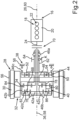
- the hybrid drive system 16 also includes a transmission 38.
- the transmission 38 has a four-shaft, first planetary gear set 40, which has at least or in this case exactly four shafts 42a-d.
- the transmission 38 also includes a second planetary gear set 44 and, in particular, exactly three shifting elements 46a-c; namely a first shifting element 46a, a second shifting element 46b and a third shifting element 46c.
- the first shifting element 46a is also referred to as SB
- the second shifting element 46b is also referred to as SK
- the third shifting element 46c is also referred to as SA.
- the shaft 42a is also referred to as the first shaft 42a
- the shaft 42b is also referred to as the second shaft 42b
- the shaft 42c is also referred to as the third shaft 42c
- the shaft 42d is also referred to as the fourth shaft 42d.
- the second planetary gear set 44 has, in particular, exactly three elements. In the Fig. 2 shown first embodiment is a first of the elements of the second Planetary gear set 44 is a third sun gear 48 of the second planetary gear set 44, a second of the elements of the planetary gear set 44 is a third ring gear 50 of the second planetary gear set 44, and the third element of the second planetary gear set 44 is a second planet carrier 52 of the second planetary gear set 44.
- the second planet carrier 52 is also referred to as a second web.
- the second planetary gear set 44 comprises second planet gears 54 of the second planetary gear set 44, which are rotatably mounted on the second planet carrier 52.
- the respective second planet gear 54 meshes directly with the sun gear 48 on the one hand and directly with the ring gear 50 of the second planetary gear set 44 on the other hand.
- the shafts 42a-d are arranged relative to one another in order to be in Fig. 2
- the particularly schematically illustrated housing 56 of the transmission 38 and thus of the hybrid drive system 16 is rotatable about a planetary gear set rotation axis 58, also referred to simply as the rotation axis.
- the planetary gear set 40 is arranged coaxially to the electric machine 28 and coaxially to the internal combustion engine 18, so that the planetary gear set rotation axis 58 (rotation axis) coincides with the machine rotation axis 36 and with the crankshaft rotation axis 26.
- at least one of the elements of the planetary gear set 44 is rotatable about an element rotation axis 60 relative to the housing 56 and/or relative to at least one other of the elements of the planetary gear set 44. From Fig. 2 it can be seen that the planning sets 40 and 44 are arranged coaxially to one another, so that the planetary set rotation axis 58 coincides with the element rotation axis 60.
- the element rotation axis 60 coincides with the machine rotation axis 36 and with the crankshaft rotation axis 26.
- the shafts 42a-d can be connected to one another in a rotationally fixed manner by means of a locking element.
- the interlocking switching element is formed by the second switching element 46b, so that the shafts 42a-d can be connected to one another in a rotationally fixed manner by means of the second switching element 46b.
- the transmission 38 comprises a third output shaft 62, via which output torques can be output from the transmission 38.
- the respective output torque results, for example, from the respective first drive torque and/or from the respective second drive torque.
- the third shaft 42c can be connected to the third output shaft 62 in a rotationally fixed manner by means of the first switching element 46a.
- Fig. 2 It can be seen that the gear 38 has a gear in the form of an output pinion 64, which is, in particular permanently, connected in a rotationally fixed manner to the output shaft 62.
- the hybrid drive system 16 can have a final gear ratio 66, also referred to as final drive or final drive ratio, which can be single-stage or multi-stage.
- the final gear ratio 66 includes the output pinion 64.
- the axle 12 comprises a differential gear 68, also simply referred to as a differential, the function of which in particular includes allowing different speeds of the wheels 14 when the motor vehicle is cornering, in particular such that the wheel on the outside of the curve rotates or can rotate at a higher speed than the wheel on the inside of the curve, in particular while the wheels 14 are driven by the internal combustion engine 18 and/or the electric machine 28 via the differential gear 68.
- a differential gear 68 also simply referred to as a differential, the function of which in particular includes allowing different speeds of the wheels 14 when the motor vehicle is cornering, in particular such that the wheel on the outside of the curve rotates or can rotate at a higher speed than the wheel on the inside of the curve, in particular while the wheels 14 are driven by the internal combustion engine 18 and/or the electric machine 28 via the differential gear 68.
- the final ratio 66 is related to a torque flow, via which the respective output torque provided by the transmission 38 via the third output shaft 62 can be transmitted or is transmitted from the output shaft 62 to the differential gear 68, in the torque flow and thereby arranged between the output shaft 62 and the differential gear 68, that is to say downstream of the output shaft 62 and upstream of the differential gear 68, wherein the final ratio 66 is the last ratio before the differential gear 68 along the torque flow flowing from the output shaft 62 to the differential gear 68.
- the hybrid drive system 16 also includes a separating clutch 70, which is also designated K0.
- the separating clutch 70 is preferably a friction clutch.
- the separating clutch 70 can be a multi-plate clutch.
- the fourth shaft 42d is connected or can be connected in a rotationally fixed manner to the first element of the second planetary gear set 44.
- the fourth shaft 42d is connected, in particular permanently, in a rotationally fixed manner to the sun gear 48 of the planetary gear set 44.
- the hybrid drive system 16 is a vehicle drive which has at least the internal combustion engine 18, the electric machine 28 and the at least or exactly four-shaft planetary gear set 40.
- the hybrid drive system 16 has a mechanical, first section 72 and a mechanical, second section 74.
- the hybrid drive system 16 comprises a node K, at or in which the sections 72 and 74 are connected or can be connected, in particular in a rotationally fixed manner.
- the node K is connected or can be connected to the drivable or driven axle 12 and thus to the wheels 14.
- the shaft 42a is coupled to the crankshaft in a rotationally fixed manner or can be coupled, in particular by means of the separating clutch 70.
- the shaft 42d is part of the mechanical section 72, which thus comprises the shaft 42d and in particular the second planet carrier 52 as a further shaft.
- the mechanical section 72 comprises a partial transmission, which in the present case is designed as the second planetary gear set 44.
- the partial transmission is directly or indirectly connected to the shaft 42d and the further shaft (planet carrier 52).
- the shaft 42c is part of the mechanical section 74, which thus comprises the shaft 42c and the switching element 46a and, as a further shaft, the output shaft 62.
- the node K comprises the output pinion 64, so that in the present case the shaft 42c can be connected in a rotationally fixed manner to the output shaft 62 and thus to the node K (output pinion 64) by means of the switching element 46a.
- the rotor shaft 34 does not have to be a separate shaft, so that it is conceivable that the rotor 32 can be directly connected to the shaft 42b or, in other words, the rotor shaft 34 can be the shaft 42b or vice versa. In other words, the rotor shaft 34 can be formed integrally with the shaft 42b or vice versa.
- the partial transmission i.e. the planetary gear set 44
- the mechanical path 72 comprises the third shifting element 46c, also designated SA, by means of which, for example in the second embodiment, the ring gear 50 of the planetary gear set 44 can be connected to the housing 56 in a rotationally fixed manner. If the shifting element SA (third shifting element 46c) is thus closed, there is a mechanical connection between one of the shafts 42a-d of the four-shaft, first planetary gear set 40 and the node K, in particular via the mechanical path 72.
- the shifting element SA can be arranged inside or outside the partial transmission.
- the second planetary gear set 44 has exactly three elements in the form of the sun gear 48, the ring gear 50 and the planet carrier 52. Furthermore, it is provided that the four-shaft, first planetary gear set 40 has exactly four shafts 42-d. In the Fig.
- the ring gear 50 which is one or the second element of the planetary gear set 44, is rotatably connected to the housing 56 by means of the third switching element 46c
- the sun gear 48 which is the or a first element of the planetary gear set 44
- the planet carrier 52 which is one or the third Element of the planetary gear set 44 is, in particular permanently, connected in a rotationally fixed manner to the output shaft 62 (third output shaft).
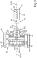
- Fig. 3 shows a second embodiment of the hybrid drive system 16.
- the ring gear 50 (second element) is, in particular permanently, connected in a rotationally fixed manner to the housing 56
- the sun gear 48 (first element) is, in particular permanently, connected in a rotationally fixed manner to the fourth shaft 42d
- the planet carrier 52 (third element) is rotatably connected to the third output shaft 62 and thus to the output pinion 64 and the node K by means of the third switching element 46c.
- the second element (ring gear 50) is connected, in particular permanently, in a rotationally fixed manner to the housing 56, and the first element (sun gear 48) can be connected in a rotationally fixed manner to the fourth shaft 42d by means of the third switching element 46c, and the third element (planet carrier 52) is connected, in particular permanently, in a rotationally fixed manner to the third output shaft 62.
- the second element can be connected to the housing 56 in a rotationally fixed manner by means of the switching element 46c
- the first element ring gear 48
- the third element plane carrier 52
- the output pinion 64 meshes directly with the differential gear 68, that is, with an input gear of the differential gear 66, designed as a ring gear, for example, or an intermediate gear can be provided such that the output pinion 64 meshes directly with the intermediate gear without meshing directly with the input gear, which meshes directly with the intermediate gear.
- the four-shaft, first planetary gear set 40 is designed such that the first shaft 42a represents a or the sum shaft in relation to the fourth shaft 42d and the third output shaft 62, in particular as soon as a gear stage in the partial transmission is actively engaged and the switching element SB (first switching element 46a) is closed and the electric machine 28 does not provide any significant torque, and that the fourth shaft 42d represents the or a sum shaft in relation to the rotor shaft 34 and the first shaft 42a as soon as a gear stage in the partial transmission is actively engaged and the switching element SB is open, and the electric machine 28 does not provide any significant torque.
- Machine 28 provides a significant torque.
- the partial transmission is of planetary design and thus designed as the second planetary gear set 44.
- the planetary gear set 44 is preferably designed as a, in particular, three-shaft planetary gear set.
- the switching element SA third switching element 46c
- the mechanical path 74 between the planetary gear set 40 and the node K does not contain a separate gear stage such as a gear pair, a planetary gear set or the like, so that the mechanical path 74 between the four-shaft, first planetary gear set 40 and the node K is preferably translated directly or with a gear ratio of 1 (1:1).
- the four-shaft, first planetary gear set 40 can preferably be blocked via a blocking switching element, which is also referred to as SK.
- the second switching element 46b is used as the blocking switching element SK.
- the switching element SK blocking switching element or second switching element 46b in its closed or switched state couples or connects at least two of the shafts 42a-d of the four-shaft, first planetary gear set 40 to one another in a rotationally fixed manner.
- the switching element SK (second switching element 46b) can be designed to be frictionally engaged.
- the switching element SK can be designed to be positively engaged.
- the switching element SK can be designed to be positively engaged and not synchronized.
- the switching element SB (first switching element 46a) can be designed to be positively locking, in particular within the mechanical section 74.
- the switching element SB in particular within the mechanical section 74, can be designed to be positively locking and not synchronized.
- the switching element SB, in particular within the mechanical section 74, can be frictionally locking.
- the internal combustion engine (internal combustion engine 18) or its crankshaft can be decoupled from the rest of the drive train 10, also referred to as the drive train, by means of the separating clutch 70.
- the separating clutch, also referred to as K0 can be frictionally engaged.
- the separating clutch K0 can be positively engaged.
- the separating clutch K0 can be positively engaged and not synchronized.
- the partial transmission and the four-shaft, first planetary gear set 40 can be connected to one another, in particular in a rotationally fixed manner, via a shaft, such as the fourth shaft 42d in the present case.
- the partial transmission can be switchable.
- the switching element SA (third switching element 46c), in particular within the mechanical section 72, can be positively locking.
- the switching element SA in particular within the mechanical section 72, can be positively locking and not synchronized.
- the switching element SA in particular within the mechanical section 72, can be frictionally locking.
- the switching element SA In its switched or closed state, the switching element SA connects one of the shafts 42a-d of the planetary gear set 44 to the housing 56 in a rotationally fixed manner.
- the electric machine 28 and the four-shaft, first planetary gear set 40 are preferably arranged coaxially with one another.
- the electric machine 28 is arranged coaxially, axially overlapping and radially surrounding the transmission 38, in particular such that the electric machine 28 is arranged coaxially, axially overlapping and radially surrounding the four-shaft, first planetary gear set 40 and/or the second planetary gear set 44.
- the electric machine 28 and the second planetary gear set 40 are arranged coaxially with one another.
- the partial transmission that is to say the second planetary gear set 44
- the partial transmission is arranged between the four-shaft, first planetary gear set 40 and the internal combustion engine 18 in the axial direction of the transmission 38 and thus along the planetary gear set rotation axis 58.
- the partial transmission i.e. the second planetary gear set 44
- the output pinion 64 also referred to as the final drive pinion, is arranged in the axial direction of the transmission 38 between the partial transmission or the second planetary gear set 44 and the internal combustion engine 18.
- the shifting element SB can be arranged in the axial direction of the transmission 38 at least essentially between the four-shaft, first planetary gear set 40 and the partial transmission or the second planetary gear set 44. It is also conceivable that the shifting element SB is arranged in the axial direction of the transmission 38 between the output pinion 64 and the internal combustion engine 18. It is also conceivable that the shifting element SB is enclosed by a hollow shaft. This is the case with the Fig. 3 shown, second embodiment is provided.
- the hollow shaft mentioned is in particular the planet carrier 52, so that preferably the switching element SB (first switching element 46a) is arranged in the hollow shaft.
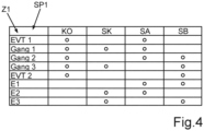
- Fig. 4 a shift table with different states EVT 1, gear 1, gear 2, gear 3, EVT 2, E1, E2 and E3 of the hybrid drive system 16.
- the states mentioned are entered in a column SP1 of the shift table.
- the separating clutch K0 and the shift elements SK, SA and SB are entered in a row Z1 of the shift table.
- a filled-in point means that the separating clutch K0 or the respective shifting element SK, SA and SB, under which the filled-in point is entered, is closed or switched. If no filled-in point is entered under the separating clutch K0 or under the shifting element SK, SB or SA, the separating clutch K0 or the respective shifting element SK, SB or SA is open.
- the EVT 1 state is therefore activated when the separating clutch K0 and the shifting element SA are closed at the same time, while the SK and SB shifting elements are open.
- the gear 1 state is activated when the separating clutch K0 and the shifting elements SK and SA are closed at the same time, while the SB shifting element is open.
- the gear 2 state is activated when the separating clutch K0 and the shifting elements SA and SB are closed at the same time, while the SK shifting element is open.
- the gear 3 state is activated when the separating clutch K0 and the shifting elements SK and SB are closed at the same time, while the SA shifting element is open.
- the EVT 2 state is activated when the separating clutch K0 and the switching element SB are closed at the same time, while the switching elements SK and SA are open.
- the E1 state is activated when the switching elements SA and SB are closed at the same time, while the separating clutch K0 and the switching element SK are open.
- the E2 state is activated when the switching elements SK and SA are closed at the same time, while the separating clutch K0 and the switching element SB are open.
- the state E3 is activated when the switching elements SK and SB are closed simultaneously, while the separating clutch K0 and the switching element SA are open.
- the hybrid drive system 16 also referred to as the drive unit, can be operated in the EVT 1 state as the first EVT mode.
- the first EVT mode is used, among other things, to start the motor vehicle in a hybrid mode in which both the internal combustion engine 18 and the electric machine 28 are involved.
- the first EVT mode can be used, among other things, for active gear ratio adjustment and speed synchronization, in particular within the shift element SB, when changing from gear 1 to gear 2.
- the electric machine 28 can be operated as a generator in the first EVT mode.
- the electric machine 28 can be operated as a motor in the first EVT mode.
- the electric machine 28 can be operated as a generator and as a motor in the first EVT mode.
- the drive unit can be operated in a second EVT mode, which is the EVT 2 state.
- the second EVT mode serves, among other things, as an overdrive mode with a long gear ratio.
- the second EVT mode can serve, among other things, for active gear ratio adjustment and speed synchronization, in particular within the shifting element SK, in particular when changing from gear 2 to gear 3.
- the second EVT mode can serve, among other things, for active gear ratio adjustment and speed synchronization, in particular within the shifting element SA, in particular when changing from gear 3 to gear 2.
- the electric machine 28 can be operated as a generator in the second EVT mode.
- the electric machine 28 can be operated as a motor in the second EVT mode.
- the electric machine 28 can be operated as a generator and as a motor in the second EVT mode.
- the first shaft 42a comprises a first sun gear 76 of the planetary gear set 40.
- the third shaft 42c comprises a second sun gear 78 of the planetary gear set 40.
- the fourth shaft 42d comprises a first planet carrier 80 of the planetary gear set 40, the first planet carrier 80 of which is, in particular permanently, rotationally fixed can be connected to the ring gear 48.
- the second shaft 42b comprises a first ring gear 82 and a second ring gear 84 of the planetary gear set 40, wherein the ring gears 82 and 84 are connected to one another in a rotationally fixed manner, in particular permanently.
- the ring gears 82 and 84 differ in their number of teeth.
- the ring gear 82 has a first number of teeth and the ring gear 84 has a second number of teeth that is different from the first number of teeth.
- First planetary gears 86 of the planetary gear set 40 are assigned to the ring gear 82
- second planetary gears 88 of the planetary gear set 44 are assigned to the ring gear 84.
- the respective planetary gear 86 meshes directly with the ring gear 82 on the one hand and directly with the sun gear 76 on the other hand
- the respective planetary gear 88 meshes directly with the sun gear 78 on the one hand and directly with the ring gear 84 on the other hand.
- Both the planetary gears 86 and the planetary gears 88 are rotatably mounted on the planet carrier 80 (shaft 42d) of the planetary set 40, which is common to the planetary gears 86 and 88.
- the planet carrier 80 is also referred to as the first web.
Landscapes
- Engineering & Computer Science (AREA)
- Mechanical Engineering (AREA)
- Chemical & Material Sciences (AREA)
- Combustion & Propulsion (AREA)
- Transportation (AREA)
- General Engineering & Computer Science (AREA)
- Hybrid Electric Vehicles (AREA)
- Retarders (AREA)
Description
- Die Erfindung betrifft ein Hybridantriebssystem für ein Kraftfahrzeug gemäß dem Oberbegriff von Patentanspruch 1. Des Weiteren betrifft die Erfindung ein Kraftfahrzeug mit einem solchen Hybridantriebssystem.
- Der
DE 10 2019 208 556 A1 , derDE 10 2007 054 359 A1 , derEP 0 787 926 A2 sind jeweils Getriebe für eine Hybridantriebsanordnung als bekannt zu entnehmen. - Die
US 2009 / 0 275 437 A1 ,DE 11 2006 001 124 T5 und dieDE 10 2010 042 005 A1 zeigen darüber hinaus Hybridantriebssysteme, jeweils mit einem Getriebe, welches einen vierwelligen ersten Planetensatz sowie einen separat von dem vierwelligen Planetensatz ausgeführten zweiten Planetensatz aufweisen. - Aufgabe der vorliegenden Erfindung ist es, ein Hybridantriebssystem für ein Kraftfahrzeug, insbesondere für einen Kraftwagen, sowie ein Kraftfahrzeug zu schaffen, so dass eine besonders bauraum- und kostengünstige Bauweise des Hybridantriebssystems realisiert werden kann.
- Diese Aufgabe wird durch ein Hybridantriebssystem mit den Merkmalen des Patentanspruchs 1 sowie durch ein Kraftfahrzeug mit den Merkmalen des Patentanspruchs 12 gelöst. Vorteilhafte Ausgestaltungen mit zweckmäßigen Weiterbildungen der Erfindung sind in den übrigen Ansprüchen angegeben.
- Ein erster Aspekt der Erfindung betrifft ein Hybridantriebssystem für ein Kraftfahrzeug, insbesondere für einen vorzugsweise als Personenkraftwagen ausgebildeten Kraftwagen. Dies bedeutet, dass das Kraftfahrzeug in seinem vollständig hergestellten Zustand das auch als Hybridantriebseinrichtung bezeichnete oder als Hybridantriebseinrichtung ausgebildete Hybridantriebssystem umfasst und mittels des Hybridantriebssystems antreibbar ist. Das Hybridantriebssystem umfasst eine auch als Verbrennungsmotor bezeichnete Verbrennungskraftmaschine, welche eine erste Abtriebswelle aufweist. Vorzugsweise ist die Verbrennungskraftmaschine als eine Hubkolbenmaschine beziehungsweise als ein Hubkolbenmotor ausgebildet, so dass die erste Abtriebswelle vorzugsweise eine Kurbelwelle ist. Über die erste Abtriebswelle kann die Verbrennungskraftmaschine auch als erste Antriebsmomente oder erste Antriebsdrehmomente bezeichnete, erste Drehmomente zum Antreiben des Kraftfahrzeugs bereitstellen. Das Hybridantriebssystem umfasst außerdem eine elektrische Maschine, welche einen Rotor mit einer Rotorwelle aufweist. Die Rotorwelle ist eine zweite Abtriebswelle, oder die Rotorwelle wird auch als zweite Abtriebswelle bezeichnet. Über die Rotorwelle kann die elektrische Maschine auch als zweite Antriebsmomente oder zweite Antriebsdrehmomente bezeichnete, zweite Drehmomente zum Antreiben des Kraftfahrzeugs bereitstellen. Beispielsweise weist die elektrische Maschine einen Stator auf, mittels welchem der Rotor antreibbar ist. Der Rotor ist um eine Maschinendrehachse relativ zu dem Stator drehbar. Die Rotorwelle ist eine zweite Abtriebswelle, oder die Rotorwelle wird auch als zweite Abtriebswelle bezeichnet. Vorzugsweise ist die elektrische Maschine eine Hochvolt-Komponente, deren elektrische Spannung, insbesondere elektrische Betriebs- oder Nennspannung, vorzugsweise größer als 50 Volt, insbesondere größer als 60 Volt, ist und ganz vorzugsweise mehrere hundert Volt beträgt. Dadurch können besonders große elektrische Leistungen zum, insbesondere rein, elektrischen Antreiben des Kraftfahrzeugs realisiert werden. Insbesondere ist die elektrische Maschine in einem Motorbetrieb und somit als Elektromotor betreibbar, mittels welchem das Kraftfahrzeug, insbesondere rein, elektrisch angetrieben werden kann. Somit stellt die elektrische Maschine in ihrem Motorbetrieb das jeweilige, zweite Antriebsmoment zum Antreiben des Kraftfahrzeugs bereit.
- Das Hybridantriebssystem umfasst ein Getriebe, welches einen vierwelligen, ersten Planetensatz aufweist. Unter dem Merkmal, dass der erste Planetensatz, welcher auch erster Planetenradsatz bezeichnet wird, ein vierwelliger Planetensatz ist, ist insbesondere zu verstehen, dass der erste Planetensatz wenigstens oder vorzugsweise genau vier Wellen aufweist, über die ein jeweiliges Drehmoment in den ersten Planetensatz einleitbar und/oder aus dem ersten Planetensatz ausleitbar ist. Das Getriebe umfasst außerdem einen insbesondere zusätzlich zu dem ersten Planetensatz vorgesehenen, zweiten Planetensatz, welcher auch als zweiter Planetenradsatz bezeichnet wird. Des Weiteren umfasst das Getriebe ein erstes Schaltelement, ein zweites Schaltelement und ein drittes Schaltelement. Das Getriebe umfasst außerdem eine dritte Abtriebswelle, über welche auch als Abtriebsmomente oder Abtriebsdrehmomente bezeichnete Drehmomente aus dem Getriebe ausgeleitet werden können. Mit anderen Worten kann das Getriebe über seine dritte Abtriebswelle Abtriebsdrehmomente zum Antreiben des Kraftfahrzeugs bereitstellen. Beispielsweise resultiert das jeweilige Abtriebsmoment aus dem jeweiligen ersten Antriebsmoment und/oder dem jeweiligen zweiten Antriebsmoment. Die Wellen des vierwelligen, ersten Planetensatzes werden auch als erste Welle, zweite Welle, dritte Welle und vierte Welle bezeichnet. Dabei weist der zweite Planetensatz ein erstes Element, ein zweites Element und ein drittes Element auf. Die Elemente des zweiten Planetensatzes werden beispielsweise auch als Getriebeelemente bezeichnet. Insbesondere kann es sich bei den Elementen des zweiten Planetensatzes um ein Sonnenrad, einen auch als Steg bezeichneten Planetenträger und ein Hohlrad des zweiten Planetensatzes handeln. Die erste Welle, die zweite Welle, die dritte Welle und die vierte Welle sind, insbesondere um eine Planetensatzdrehachse, relativ zueinander und beispielsweise relativ zu einem Gehäuse des Hybridantriebssystems drehbar. Dabei ist es denkbar, dass der erste Planetensatz und/oder der zweite Planetensatz jeweils zumindest teilweise in dem Gehäuse angeordnet sind. Die erste Welle, die zweite Welle, die dritte Welle und die vierte Welle sind mittels eines Verblockungsschaltelements des Hybridantriebssystems drehfest miteinander verbindbar. Dabei ist es denkbar, dass das Verblockungsschaltelement zusätzlich zu den zuvor genannten Schaltelementen vorgesehen und somit ein viertes Schaltelement ist, oder das Verblockungsschaltelement ist durch eines der zuvor genannten Schaltelemente gebildet. Die Planetensatzdrehachse wird auch einfach als Drehachse bezeichnet.
- Die erste Abtriebswelle ist drehfest mit der ersten Welle gekoppelt oder koppelbar. Hierunter ist insbesondere zu verstehen, dass die erste Abtriebswelle permanent drehfest mit der ersten Welle verbunden ist, oder die erste Abtriebswelle ist drehfest mit der ersten Welle verbindbar.
- Im Rahmen der vorliegenden Offenbarung ist unter dem Merkmal, dass zwei Bauelemente drehfest miteinander verbunden sind, zu verstehen, dass die Bauelemente koaxial zueinander angeordnet und derart miteinander verbunden sind, dass sie mit gleicher Winkelgeschwindigkeit gemeinsam um eine den Bauelementen gemeinsame Bauelementdrehachse drehen.
- Unter dem Merkmal, dass die beziehungsweise zwei Bauelemente permanent drehfest miteinander verbunden sind, ist zu verstehen, dass nicht etwa ein Umschaltelement vorgesehen ist, welches zwischen einem die Bauelemente drehfest miteinander verbindenden Koppelzustand und einem die Bauelemente für eine insbesondere um die Bauelementdrehachse erfolgende Drehung relativ zueinander freigebenden Entkoppelzustand umschaltbar ist, sondern die Bauelemente sind stets beziehungsweise permanent drehfest miteinander verbunden.
- Unter dem Merkmal, dass die beziehungsweise zwei Bauelemente drehfest miteinander verbindbar sind, ist zu verstehen, dass den Bauelementen ein Umschaltelement zugeordnet ist, welches zwischen wenigstens einem Koppelzustand und wenigstens einem Entkoppelzustand umschaltbar ist. In dem Koppelzustand sind die Bauelemente mittels des Umschaltelements fest miteinander verbunden. In dem Entkoppelzustand sind die Bauelemente voneinander entkoppelt, so dass in dem Entkoppelzustand die Bauelemente relativ zueinander insbesondere um die Bauelementdrehachse drehbar sind.
- Bei dem Hybridantriebssystem ist es außerdem vorgesehen, dass die Rotorwelle derart mit der zweiten Welle, insbesondere drehfest, gekoppelt oder koppelbar ist, dass von der Rotorwelle ausgehende beziehungsweise bereitgestellte Drehmomente, wie beispielsweise die zweiten Antriebsmomente, über die zweite Welle in das Getriebe einleitbar sind beziehungsweise eingeleitet werden. Des Weiteren ist es vorgesehen, dass die dritte Welle mittels des ersten Schaltelements drehfest mit der dritten Abtriebswelle verbindbar ist. Hierunter ist insbesondere Folgendes zu verstehen: Das erste Schaltelement ist zwischen einem ersten Koppelzustand und einem ersten Entkoppelzustand umschaltbar. In dem ersten Koppelzustand ist die dritte Welle mittels des ersten Schaltelements drehfest mit der dritten Abtriebswelle verbunden. In dem ersten Entkoppelzustand gibt das erste Schaltelement die dritte Welle und die dritte Abtriebswelle derart frei, dass in dem ersten Entkoppelzustand die dritte Welle relativ zu der dritten Abtriebswelle drehbar ist beziehungsweise umgekehrt. Dabei ist beispielsweise das erste Schaltelement, insbesondere relativ zu dem Gehäuse und/oder translatorisch, zwischen wenigstens einer ersten Koppelstellung und wenigstens einer ersten Entkoppelstellung bewegbar. Die erste Koppelstellung bewirkt den ersten Koppelzustand, und die erste Entkoppelstellung bewirkt den ersten Entkoppelzustand.
- Um nun eine besonders bauraum- und kostengünstige Bauweise des Hybridantriebssystems realisieren zu können, ist es ferner auf bekannte Weise vorgesehen, dass die vierte Welle drehfest mit dem ersten Element des zweiten Planetensatzes verbunden beziehungsweise gekoppelt oder verbindbar beziehungsweise koppelbar ist. Hierdurch kann insbesondere in axialer Richtung des Getriebes und somit des Hybridantriebssystems eine besonders kompakte Bauweise realisiert werden. Im Rahmen der vorliegenden Offenbarung bezieht sich die Bezeichnung "axial" auf die Planetensatzdrehachse, so dass insbesondere entlang der Planetensatzdrehachse betrachtet eine besonders kompakte, das heißt kurze Bauweise des Hybridantriebssystems geschaffen werden kann. Wieder mit anderen Worten ausgedrückt kann eine besonders geringe, entlang der axialen Richtung des Getriebes verlaufende Länge des Hybridantriebssystems realisiert werden. Außerdem können Komponenten in axialer Richtung des Getriebes besonders nahe an der Verbrennungskraftmaschine angeordnet werden, so dass ein besonders geringer Bauraumbedarf des Hybridantriebssystems darstellbar ist. Des Weiteren können die Kosten des erfindungsgemäßen Hybridantriebssystems besonders gering gehalten werden. In der Folge kann das Getriebe insbesondere als Hybridmehrganggetriebe vorteilhaft in das Kraftfahrzeug integriert werden. Durch Verwendung der Schaltelemente kann das Getriebe Mehrganggetriebe ausgebildet werden. Dies bedeutet, dass mehrere, schaltbare und somit einlegbare und auslegbare Gänge des Getriebes geschaffen werden können, dessen Gänge sich beispielsweise in ihren jeweiligen Übersetzungen voneinander unterscheiden. Außerdem ist es möglich, zumindest einen der Gänge, mehrere der Gänge oder alle Gänge des Getriebes lastschaltfähig auszuführen.
- Besonders vorteilhaft ist dabei die vierte Welle unter Umgehung des ersten Schaltelementes drehfest mit dem ersten Element des zweiten Planetensatzes verbunden oder verbindbar.
- Im Rahmen der vorliegenden Offenbarung sind unter koaxial zueinander angeordneten, drehbaren Bauteilen solche Bauteile oder Bauelemente zu verstehen, die insbesondere relativ zu dem Gehäuse um eine jeweilige Bauelementdrehachse drehbar sind, wobei die Bauelementdrehachsen koaxial zueinander verlaufen beziehungsweise zusammenfallen.
- Erfindungsgemäß ist vorgesehen, dass die erste Welle ein erstes Sonnenrad des ersten Planetensatzes umfasst, wobei die dritte Welle ein zweites Sonnenrad des ersten Planetensatzes umfasst. Hierdurch kann auf besonders bauraum-, gewichts- und kostengünstige Weise ein besonders effizienter Antrieb des Kraftfahrzeugs realisiert werden.
- Um den Bauraumbedarf, das Gewicht und die Kosten des Hybridantriebssystems besonders gering halten zu können, ist es bei einer vorteilhaften Ausführungsform der Erfindung vorgesehen, dass der zweite Planetensatz genau drei Elemente in Form der zuvor genannten Elemente aufweist.
- Eine weitere Ausführungsform zeichnet sich dadurch aus, dass der vierwellige, erste Planetensatz genau vier Wellen in Form der zuvor genannten Wellen aufweist. Hierdurch kann ein besonders bauraum-, gewichts- und kostengünstiger Aufbau des Hybridantriebssystems dargestellt werden. Bevorzugt weist der erste Planetensatz sechs Getriebeelemente des ersten Planetensatzes auf, nämlich bevorzugt 2 Sonnenräder, zwei Planetenträger und zwei Hohlräder. Diesen sechs Getriebeelementen des ersten Planetensatzes ordnet der Fachmann zunächst jeweils eine Welle, also insgesamt sechs Wellen des ersten Planetensatzes, zu. Bevorzugt sind zwei der sechs Elemente des ersten Planetensatzes drehfest miteinander verbunden. Und es sind bevorzugt weitere zwei der sechs Element des ersten Planetensatzes drehfest miteinander verbunden. Bevorzugt hat auf diese Weise der erste Planetensatz die vier relativ zueinander drehbar angeordneten Wellen.
- Bei einer weiteren, besonders vorteilhaften Ausführungsform der Erfindung ist das zweite Element des zweiten Planetensatzes mittels des dritten Schaltelements mit dem Gehäuse drehfest verbindbar. Somit ist beispielsweise das dritte Schaltelement zwischen einem zweiten Koppelzustand und einem zweiten Entkoppelzustand umschaltbar. In dem zweiten Koppelzustand ist das zweite Element mittels des dritten Schaltelements drehfest mit dem Gehäuse verbunden, so dass Relativdrehungen zwischen dem Gehäuse und dem zweiten Element unterbleiben. In dem zweiten Entkoppelzustand gibt das dritte Schaltelement das zweite Element für eine um das Gehäuse erfolgende Drehung frei, so dass in dem zweiten Entkoppelzustand das zweite Element relativ zu dem Gehäuse drehbar ist, insbesondere um eine Elementdrehachse, welche eine Drehachse des zweiten Planetensatzes ist. Dabei ist es besonders bevorzugt vorgesehen, dass die Planungssätze koaxial zueinander angeordnet sind, so dass die Planetensatzdrehachse, um welche die Wellen, insbesondere relativ zu dem Gehäuse und/oder relativ zueinander, drehbar sind, mit der Elementdrehachse des zweiten Planetensatzes zusammenfällt. Dabei ist beispielsweise das dritte Schaltelement, insbesondere relativ zu dem Gehäuse und/oder translatorisch, zwischen wenigstens einer den zweiten Koppelzustand bewirkenden, zweiten Koppelstellung und/oder wenigstens einer den zweiten Entkoppelzustand bewirkenden, zweiten Entkoppelstellung bewegbar.
- Dabei ist es ferner vorzugsweise vorgesehen, dass das erste Element, insbesondere permanent, drehfest mit der vierten Welle verbunden beziehungsweise gekoppelt ist. Außerdem ist es bei dieser Ausführungsform vorzugsweise vorgesehen, dass das dritte Element, insbesondere permanent, drehfest mit der dritten Abtriebswelle verbunden beziehungsweise gekoppelt ist. Dadurch kann ein besonders kompakter Aufbau des Hybridantriebssystems realisiert werden.
- Um alternativ eine besonders kompakte Bauweise des Hybridantriebssystems insbesondere in axialer Richtung des Getriebes realisieren zu können, ist es bei einer weiteren Ausführungsform der Erfindung vorgesehen, dass das zweite Element, insbesondere permanent, drehfest mit dem Gehäuse verbunden ist. Dabei hat es sich als besonders vorteilhaft gezeigt, wenn das erste Element mittels des dritten Schaltelements drehfest mit der vierten Welle verbindbar ist. Bei dieser Ausführungsform ist es somit vorgesehen, dass in dem zweiten Koppelzustand das erste Element mittels des dritten Schaltelements drehfest mit der vierten Welle verbunden ist, wobei das dritte Schaltelement in dem zweiten Entkoppelzustand das erste Element und die vierte Welle derart freigibt, dass das erste Element und die vierte Welle, insbesondere um die Planetensatzdrehachse beziehungsweise um die Elementdrehachse, relativ zueinander drehbar sind. Außerdem zeichnen sich diese Ausführungsformen dadurch aus, dass das dritte Element, insbesondere permanent, drehfest mit der dritten Abtriebswelle verbunden ist.
- Bei einer weiteren, alternativen und besonders vorteilhaften Ausführungsform der Erfindung ist es vorgesehen, dass das zweite Element, insbesondere permanent, drehfest mit dem Gehäuse verbunden ist. Dabei ist das erste Element, insbesondere permanent, drehfest mit der vierten Welle verbunden, und das dritte Element ist mittels des dritten Schaltelements drehfest mit der dritten Abtriebswelle verbindbar. Somit ist es bei dieser Ausführungsform vorzugsweise vorgesehen, dass in dem zweiten Koppelzustand das dritte Element mittels des dritten Schaltelements drehfest mit der dritten Abtriebswelle verbunden ist, wobei in dem zweiten Entkoppelzustand das dritte Schaltelement das dritte Element und die dritte Abtriebswelle derart freigibt, dass das dritte Element und die dritte Abtriebswelle, insbesondere um die Planetensatzdrehachse beziehungsweise um die Elementdrehachse, relativ zueinander drehbar sind. Dadurch kann insbesondere in axialer Richtung des Getriebes betrachtet eine besonders geringe Länge des Hybridantriebssystems dargestellt werden.
- Um die Teileanzahl und somit die Kosten, das Gewicht und den Bauraumbedarf des Hybridantriebssystems besonders gering halten zu können, ist es in weiterer Ausgestaltung der Erfindung vorgesehen, dass insgesamt genau drei Schaltelemente in Form des ersten Schaltelements, des als das Verblockungsschaltelement ausgebildeten zweiten Schaltelements und des dritten Schaltelements vorgesehen sind. Mit anderen Worten umfasst das Hybridantriebssystem genau drei Schaltelemente in Form der zuvor genannten Schaltelemente, wobei das erste Schaltelement als das Verblockungsschaltelement ausgebildet ist. Außerdem können hierdurch beispielsweise besonders vorteilhaft die zuvor genannten und insbesondere lastschaltfähigen Gänge dargestellt werden, so dass das Getriebe besonders bauraum-, gewichts- und kostengünstig als Mehrganggetriebe abgeführt werden kann.
- Eine weitere Ausführungsform zeichnet sich dadurch aus, dass die elektrische Maschine koaxial, axial überlappend sowie radial umgebend zu dem Getriebe angeordnet ist. Hierunter ist insbesondere Folgendes zu verstehen: Unter dem Merkmal, dass die elektrische Maschine koaxial zu dem Getriebe angeordnet ist, ist zu verstehen, dass die Maschinendrehachse, um welche der Rotor relativ zu dem Stator drehbar ist, mit der Planetensatzdrehachse des ersten Planetensatzes und somit vorzugsweise auch mit der Elementdrehachse des zweiten Planetensatzes zusammenfällt. Unter dem Merkmal, dass die elektrische Maschine axial überlappend zu dem Getriebe angeordnet ist, ist insbesondere zu verstehen, dass zumindest ein erster Längenbereich des Getriebes, insbesondere zumindest ein erster Längenbereich des ersten Planetensatzes und/oder des zweiten Planetensatzes, in radialer Richtung des Getriebes, das heißt entlang einer senkrecht zur Planetensatzdrehachse verlaufenden Richtung nach außen hin zumindest durch einen zweiten Längenbereich der elektrischen Maschine überlappt beziehungsweise überdeckt ist. Des Weiteren ist unter dem Merkmal, dass die elektrische Maschine radial umgebend zu dem Getriebe angeordnet ist, zu verstehen, dass zumindest der zweite Längenbereich der elektrischen Maschine, zumindest den ersten Längenbereich des Getriebes in um die Planetensatzdrehachse verlaufender Umfangsrichtung des Getriebes vollständig umlaufend umgibt, so dass der erste Längenbereich in dem zweiten Längenbereich angeordnet ist. Dadurch kann eine besonders kompakte Bauweise des Hybridantriebssystems dargestellt werden.
- Bei einer weiteren, besonders vorteilhaften Ausführungsform der Erfindung ist es vorgesehen, dass die zweite Welle ein erstes Hohlrad des ersten Planetensatzes und ein, insbesondere permanent, drehfest mit dem ersten Hohlrad verbundenes, zweites Hohlrad des ersten Planetensatzes umfasst beziehungsweise ist. Dadurch können die Teileanzahl und somit die Kosten, Bauraumbedarf und das Gewicht des Hybridantriebssystems in einem besonders geringen Rahmen gehalten werden.
- Bei einer weiteren, besonders vorteilhaften Ausführungsform der Erfindung ist es vorgesehen, dass die vierte Welle einen ersten Planetenträger des ersten Planetensatzes umfasst, dessen erster Planetenträger beispielsweise, insbesondere permanent, drehfest mit dem als zweiter Planetenträger bezeichneten, zweiten Planetenträger des zweiten Planetensatzes verbunden sein kann. Hierdurch lässt sich auf besonders bauraumgünstige Weise ein besonders vorteilhafter Antrieb des Kraftfahrzeugs darstellen.
- Schließlich hat es sich als besonders vorteilhaft gezeigt, wenn die Verbrennungskraftmaschine, ein Abtriebsritzel, welches, insbesondere permanent, drehfest mit der dritten Abtriebswelle verbunden ist, der zweite Planetensatz und der vierwellige, erste Planetensatz in axialer Richtung des Getriebes und somit entlang der Planetensatzdrehachse betrachtet, in folgender Reihenfolge angeordnet sind: die Verbrennungskraftmaschine - das Abtriebsritzel - der zweite Planetensatz - der vierwellige, erste Planetensatz. Mit anderen Worten ist es vorzugsweise vorgesehen, dass in axialer Richtung des Getriebes und somit entlang der Planetensatzdrehachse betrachtet das Abtriebsritzel auf die Verbrennungskraftmaschine, der zweite Planetensatz auf das Abtriebsritzel und der vierwellige, erste Planetensatz auf den zweiten Planetensatz folgt. Dadurch kann die axiale Länge des Hybridantriebssystems in einem besonders geringen Rahmen gehalten werden.
- Ein zweiter Aspekt der Erfindung betrifft ein vorzugsweise als Kraftwagen, insbesondere als Personenkraftwagen, ausgebildetes Kraftfahrzeug, welches ein Hybridantriebssystem gemäß dem ersten Aspekt der Erfindung aufweist und mittels des Hybridantriebssystems antreibbar ist. Somit ist das Kraftfahrzeug als Hybridfahrzeug ausgebildet. Vorteile und vorteilhafte Ausgestaltungen des ersten Aspekts der Erfindung sind als Vorteile und vorteilhafte Ausgestaltungen des zweiten Aspekts der Erfindung anzusehen und umgekehrt. Da die in axialer Richtung des Getriebes verlaufende Länge des Hybridantriebssystems besonders gering gehalten werden kann, kann das Hybridantriebssystem besonders vorteilhaft quer eingebaut, das heißt als Quereinbau verwendet werden. Hierunter ist zu verstehen, dass in vollständig hergestelltem Zustand des Kraftfahrzeugs die axiale Richtung des Getriebes und somit des Hybridantriebssystems insgesamt quer beziehungsweise senkrecht zur Fahrzeuglängsrichtung (y-Richtung) verläuft.
- Weitere Vorteile, Merkmale und Einzelheiten der Erfindung ergeben sich aus der nachfolgenden Beschreibung bevorzugter Ausführungsbeispiele sowie anhand der Zeichnung. Die vorstehend in der Beschreibung genannten Merkmale und Merkmalskombinationen sowie die nachfolgend in der Figurenbeschreibung genannten und/oder in den Figuren alleine gezeigten Merkmale und Merkmalskombinationen sind nicht nur in der jeweils angegebenen Kombination, sondern auch in anderen Kombinationen oder in Alleinstellung verwendbar, ohne den Rahmen der Erfindung zu verlassen.
- Die Zeichnung zeigt in:
- Fig. 1
- eine schematische Darstellung eines Antriebsstrangs für ein Kraftfahrzeug, mit einem erfindungsgemäßen Hybridantriebssystem;
- Fig. 2
- eine schematische Darstellung des Hybridantriebssystems gemäß einer ersten Ausführungsform;
- Fig. 3
- eine schematische Darstellung des Hybridantriebssystems gemäß einer zweiten Ausführungsform; und
- Fig. 4
- eine Schalttabelle zur Erläuterung von unterschiedlichen Betriebszuständen des Hybridantriebssystems.
- In den Figuren sind gleiche oder funktionsgleiche Elemente mit gleichen Bezugszeichen versehen.
-
Fig. 1 zeigt in einer schematischen Darstellung einen Antriebsstrang 10 für ein vorzugsweise als Kraftwagen, insbesondere als Personenkraftwagen, ausgebildetes Kraftfahrzeug. In seinem vollständig hergestellten Zustand weist das Kraftfahrzeug wenigstens oder genau zwei in Fahrzeuglängsrichtung (x-Richtung) hintereinander angeordnete und auch als Fahrzeugachsen bezeichnete Achsen auf, wobei der Antriebsstrang 10 eine der Achsen umfasst. Die Achse des Antriebsstrangs 10 ist inFig. 2 mit 12 bezeichnet. Die Achse 12 weist wenigstens oder genau zwei in Fahrzeugquerrichtung (y-Richtung) gegenüberliegende und auch als Fahrzeugräder bezeichnete Räder 14 auf, welche antreibbare oder angetriebene Räder sind. Durch Antreiben der Räder 14 wird das Kraftfahrzeug insgesamt angetrieben. Der Antriebsstrang 10 umfasst ein Hybridantriebssystem 16, mittels welchem die Räder 14 und somit das Kraftfahrzeug antreibbar sind. Das Hybridantriebssystem 16 weist eine auch als Brennkraftmaschine oder Verbrennungsmotor bezeichnete Verbrennungskraftmaschine 18 auf. AusFig. 1 ist erkennbar, dass die Verbrennungskraftmaschine 18 einen Motorblock 20 aufweist, welcher mehrere Zylinder 22 bildet beziehungsweise, insbesondere direkt, begrenzt. Der jeweilige Zylinder 22 begrenzt teilweise einen jeweiligen Brennraum, in welchem während eines befeuerten Betriebs der Verbrennungskraftmaschine 18 Verbrennungsvorgänge ablaufen. Die Verbrennungskraftmaschine 18 weist eine erste Abtriebswelle 24 auf, welche vorliegend als eine Kurbelwelle ausgebildet ist. Dabei ist die Verbrennungskraftmaschine 18 als ein Hubkolbenmotor ausgebildet. Die Kurbelwelle (erste Abtriebswelle 24) ist um eine Kurbelwellendrehachse 26 relativ zu dem Motorblock 20 drehbar. Über die Kurbelwelle kann die Verbrennungskraftmaschine 18 erste Antriebsmomente zum Antreiben des Kraftfahrzeugs bereitstellen. - Das Hybridantriebssystem 16 umfasst außerdem eine in
Fig. 1 besonders schematisch dargestellte, elektrische Maschine 28. Wie ausFig. 2 erkennbar ist, welche eine erste Ausführungsform des Hybridantriebssystems 16 zeigt, weist die elektrische Maschine 28 einen Stator 30 und einen Rotor 32 auf, welcher eine Rotorwelle 34 umfasst. Der Rotor 32 und somit die Rotorwelle 34 sind um eine Maschinendrehachse 36 relativ zu dem Stator 30 und auch relativ zu dem Motorblock 20 drehbar. AusFig. 2 ist erkennbar, dass die elektrische Maschine 28 koaxial zu der Verbrennungskraftmaschine 18 angeordnet ist, so dass die Maschinendrehachse 36 mit der Kurbelwellendrehachse 26 zusammenfällt. Der Rotor 32 beziehungsweise die Rotorwelle 34 ist eine zweite Abtriebswelle, über welche die elektrische Maschine 28, insbesondere in ihrem Motorbetrieb, zweite Antriebsmomente zum Antreiben des Kraftfahrzeugs beziehungsweise der Räder 14 bereitstellen kann. - Das Hybridantriebssystem 16 umfasst außerdem ein Getriebe 38. Das Getriebe 38 weist einen vierwelligen, ersten Planetensatz 40 auf, welcher wenigstens oder vorliegend genau vier Wellen 42a-d aufweist. Das Getriebe 38 umfasst außerdem einen zweiten Planetensatz 44 und, insbesondere genau, drei Schaltelemente 46a-c; nämlich ein erstes Schaltelement 46a, ein zweites Schaltelement 46b und ein drittes Schaltelement 46c. Das erste Schaltelement 46a wird auch mit SB bezeichnet, das zweite Schaltelement 46b wird auch mit SK bezeichnet, und das dritte Schaltelement 46c wird auch mit SA bezeichnet. Die Welle 42a wird auch als erste Welle 42a, die Welle 42b wird auch als zweite Welle 42b bezeichnet, die Welle 42c wird auch als dritte Welle 42c bezeichnet, und die Welle 42d wird auch als vierte Welle 42d bezeichnet. Der zweite Planetensatz 44 weist, insbesondere genau, drei Elemente auf. Bei der in
Fig. 2 gezeigten, ersten Ausführungsform ist ein erstes der Elemente des zweiten Planetensatzes 44 ein drittes Sonnenrad 48 des zweiten Planetensatzes 44, ein zweites der Elemente des Planetensatzes 44 ist ein drittes Hohlrad 50 des zweiten Planetensatzes 44, und das dritte Element des zweiten Planetensatzes 44 ist ein zweiter Planetenträger 52 des zweiten Planetensatzes 44. Der zweite Planetenträger 52 wird auch als zweiter Steg bezeichnet. Dabei umfasst der zweite Planetensatz 44 zweite Planetenräder 54 des zweiten Planetensatzes 44, welche drehbar an dem zweiten Planetenträger 52 gelagert sind. Das jeweilige zweite Planetenrad 54 kämmt dabei einerseits direkt mit dem Sonnenrad 48 und andererseits direkt mit dem Hohlrad 50 des zweiten Planetensatzes 44. Die Wellen 42a-d sind relativ zueinander um relativ zueinander inFig. 2 besonders schematisch dargestellte Gehäuse 56 des Getriebes 38 und somit des Hybridantriebssystems 16 drehbar und zwar um eine einfach auch als Drehachse bezeichnete Planetensatzdrehachse 58. AusFig. 2 ist erkennbar, dass der Planetensatz 40 koaxial zu der elektrischen Maschine 28 und koaxial zu der Verbrennungskraftmaschine 18 angeordnet ist, so dass die Planetensatzdrehachse 58 (Drehachse) mit der Maschinendrehachse 36 und mit der Kurbelwellendrehachse 26 zusammenfällt. Außerdem ist zumindest eines der Elemente des Planetensatzes 44 um eine Elementdrehachse 60 relativ zu dem Gehäuse 56 und/oder relativ zu wenigstens einem weiteren der Elemente des Planetensatzes 44 drehbar. AusFig. 2 ist erkennbar, dass die Planungssätze 40 und 44 koaxial zueinander angeordnet sind, so dass die Planetensatzdrehachse 58 mit der Elementdrehachse 60 zusammenfällt. Außerdem fällt die Elementdrehachse 60 mit der Maschinendrehachse 36 und mit der Kurbelwellendrehachse 26 zusammen. Des Weiteren sind die Wellen 42a-d mittels eines Verblockungselements drehfest miteinander verbindbar. Bei der inFig. 2 gezeigten, ersten Ausführungsform ist das Verblockungsschaltelement durch das zweite Schaltelement 46b gebildet, so dass die Wellen 42a-d mittels des zweiten Schaltelements 46b drehfest miteinander verbindbar sind. - Das Getriebe 38 umfasst eine dritte Abtriebswelle 62, über welche Abtriebsdrehmomente aus dem Getriebe 38 ausleitbar sind. Das jeweilige Abtriebsmoment resultiert beispielsweise aus dem jeweiligen, ersten Antriebsmoment und/oder aus dem jeweiligen, zweiten Antriebsmoment. Dabei ist die dritte Welle 42c mittels des ersten Schaltelements 46a drehfest mit der dritten Abtriebswelle 62 verbindbar. Aus
Fig. 2 ist erkennbar, dass das Getriebe 38 ein Zahnrad in Form eines Abtriebsritzels 64 aufweist, welches, insbesondere permanent, drehfest mit der Abtriebswelle 62 verbunden ist. AusFig. 1 ist erkennbar, dass das Hybridantriebssystem 16 eine auch als Final-Drive oder Final-Drive-Übersetzung bezeichnete Endübersetzung 66 aufweisen kann, welche einstufig oder mehrstufig sein kann. Die Endübersetzung 66 umfasst das Abtriebsritzel 64. Dabei umfasst die Achse 12 ein einfach auch als Differential bezeichnetes Differentialgetriebe 68, dessen Funktion insbesondere umfasst, bei einer Kurvenfahrt des Kraftfahrzeugs unterschiedliche Drehzahlen der Räder 14 zuzulassen, insbesondere derart, dass sich das kurvenäußere Rad mit einer größeren Drehzahl dreht oder drehen kann als das kurveninnere Rad, insbesondere während die Räder 14 über das Differentialgetriebe 68 von der Verbrennungskraftmaschine 18 und/oder der elektrischen Maschine 28 angetrieben werden. Die Endübersetzung 66 ist dabei bezogen auf einen Drehmomentenfluss, über welchen das jeweilige, von dem Getriebe 38 über die dritte Abtriebswelle 62 bereitgestellte Abtriebsmoment von der Abtriebswelle 62 auf das Differentialgetriebe 68 übertragbar ist beziehungsweise übertragen wird, in dem Drehmomentenfluss und dabei zwischen der Abtriebswelle 62 und dem Differentialgetriebe 68, das heißt stromab der Abtriebswelle 62 und stromauf des Differentialgetriebes 68 angeordnet, wobei die Endübersetzung 66 entlang des von der Abtriebswelle 62 hin zu dem Differentialgetriebe 68 fließenden Drehmomentenflusses die letzte Übersetzung vor dem Differentialgetriebe 68 ist. - Das Hybridantriebssystem 16 umfasst außerdem eine Trennkupplung 70, welche auch mit K0 bezeichnet wird. Die Trennkupplung 70 ist vorzugsweise eine Reibkupplung. Insbesondere kann die Trennkupplung 70 eine Lamellenkupplung sein. Mittels der Trennkupplung 70 kann die Kurbelwelle (Abtriebswelle 24) drehfest mit der ersten Welle 42a verbunden werden.
- Um eine besonders bauraum- und kostengünstige Bauweise des Hybridantriebssystems 16 realisieren zu können, ist die vierte Welle 42d drehfest mit dem ersten Element des zweiten Planetensatzes 44 verbunden oder verbindbar. Somit ist es bei der in
Fig. 2 gezeigten ersten Ausführungsform vorgesehen, dass die vierte Welle 42d, insbesondere permanent, drehfest mit dem Sonnenrad 48 des Planetensatzes 44 verbunden ist. - Aus
Fig. 1 und2 erkennbar, dass das Hybridantriebssystem 16 ein Fahrzeugantrieb ist, welcher zumindest die Verbrennungskraftmaschine 18, die elektrische Maschine 28 und den zumindest oder genau vierwelligen Planetensatz 40 aufweist. Außerdem weist das Hybridantriebssystem 16 eine mechanische, erste Strecke 72 und eine mechanische, zweite Strecke 74 auf. Des Weiteren umfasst das Hybridantriebssystem 16 einen Knoten K, an oder in dem die Strecken 72 und 74, insbesondere drehfest, verbunden oder verbindbar sind. Der Knoten K ist dabei mit der antreibbaren oder angetriebenen Achse 12 und somit mit den Rädern 14 verbunden oder verbindbar. Bei der ersten Ausführungsform ist die Welle 42a mit der Kurbelwelle drehfest gekoppelt oder koppelbar, insbesondere mittels der Trennkupplung 70. Beispielsweise die Welle 42d ist Teil der mechanischen Strecke 72, die somit die Welle 42d und insbesondere als weitere Welle den zweiten Planetenträger 52 umfasst. Außerdem umfasst die mechanische Strecke 72 ein Teilgetriebe, welches vorliegend als der zweite Planetensatz 44 ausgebildet ist. Das Teilgetriebe ist dabei direkt oder indirekt mit der Welle 42d und der weiteren Welle (Planetenträger 52) verbunden. Beispielsweise die Welle 42c ist Bestandteil der mechanischen Strecke 74, welche somit die Welle 42c und das Schaltelement 46a sowie als weitere Welle die Abtriebswelle 62 umfasst. Vorliegend umfasst beispielsweise der Knoten K das Abtriebsritzel 64, so dass vorliegend die Welle 42c mittels des Schaltelements 46a drehfest mit der Abtriebswelle 62 und somit mit dem Knoten K (Abtriebsritzel 64) verbindbar ist. Die Rotorwelle 34 muss keine separate Welle sein, so dass es denkbar ist, dass der Rotor 32 direkt mit der Welle 42b verbindbar oder verbunden sein kann beziehungsweise mit anderen Worten kann die Rotorwelle 34 die Welle 42b sein beziehungsweise umgekehrt. Wieder mit anderen Worten ausgedrückt kann die Rotorwelle 34 einstückig mit der Welle 42b ausgebildet sein beziehungsweise umgekehrt. - Vorzugsweise weist das Teilgetriebe, das heißt der Planetensatz 44, eine Übersetzung von ungleich 1:1 beziehungsweise eine Übersetzungsstufe auf, deren Übersetzung ungleich 1:1 ist. Außerdem umfasst die mechanische Strecke 72 das auch mit SA bezeichnete, dritte Schaltelement 46c, mittels welchem beispielsweise bei der zweiten Ausführungsform das Hohlrad 50 des Planetensatzes 44 drehfest mit dem Gehäuse 56 verbindbar ist. Ist somit das Schaltelement SA (drittes Schaltelement 46c) geschlossen, besteht zwischen einer der Wellen 42a-d des vierwelligen, ersten Planetensatzes 40 und dem Knoten K, insbesondere über die mechanische Strecke 72, eine mechanische Verbindung. Das Schaltelement SA kann dabei innerhalb oder außerhalb des Teilgetriebes angeordnet sein.
- Es ist erkennbar, dass bei der ersten Ausführungsform der zweite Planetensatz 44 genau drei Elemente in Form des Sonnenrads 48, des Hohlrads 50 und des Planetenträgers 52 aufweist. Ferner ist es vorgesehen, dass der vierwellige, erste Planetensatz 40 genau vier Wellen 42-d aufweist. Bei der in
Fig. 2 gezeigten ersten Ausführungsform ist das Hohlrad 50, welches ein beziehungsweise das zweite Element des Planetensatzes 44 ist, mittels des dritten Schaltelements 46c drehfest mit dem Gehäuse 56 verbindbar, und das Sonnenrad 48, welches das oder ein erstes Element des Planetensatzes 44 ist, ist, insbesondere permanent, drehfest mit der vierten Welle 42d verbunden, und der Planetenträger 52, welcher ein beziehungsweise das dritte Element des Planetensatzes 44 ist, ist, insbesondere permanent, drehfest mit der Abtriebswelle 62 (dritte Abtriebswelle) verbunden. -
Fig. 3 zeigt eine zweite Ausführungsform des Hybridantriebssystems 16. Bei der zweiten Ausführungsform ist das Hohlrad 50 (zweites Element), insbesondere permanent, drehfest mit dem Gehäuse 56 verbunden, und das Sonnenrad 48 (erstes Element) ist, insbesondere permanent, drehfest mit der vierten Welle 42d verbunden, und der Planetenträger 52 (drittes Element) ist mittels des dritten Schaltelements 46c drehfest mit der dritten Abtriebswelle 62 und somit mit dem Abtriebsritzel 64 und dem Knoten K verbindbar. - Bei einer in den Figuren nicht gezeigten, dritten Ausführungsform ist das zweite Element (Hohlrad 50), insbesondere permanent, drehfest mit dem Gehäuse 56 verbunden, und das erste Element (Sonnenrad 48) ist mittels des dritten Schaltelements 46c drehfest mit der vierten Welle 42d verbindbar, und das dritte Element (Planetenträger 52) ist, insbesondere permanent, drehfest mit der dritten Abtriebswelle 62 verbunden.
- Bei einer weiteren Ausführungsform ist es denkbar, dass das zweite Element (Hohlrad 50) mittels des Schaltelements 46c drehfest mit dem Gehäuse 56 verbindbar ist, und das erste Element (Hohlrad 48), insbesondere permanent, drehfest mit der vierten Welle 42d verbunden ist, und mittels des zweiten Schaltelements 46b das dritte Element (Planetenträger 52) drehfest mit der dritten Welle 42c verbindbar ist.
- Grundsätzlich ist es denkbar, dass das Abtriebsritzel 64 direkt mit dem Differentialgetriebe 68, das heißt mit einem beispielsweise als Tellerrad ausgebildeten Eingangsrad des Differentialgetriebes 66 kämmt, oder es kann ein Zwischenzahnrad vorgesehen sein, derart, dass das Abtriebsritzel 64 direkt mit dem Zwischenzahnrad kämmt, ohne direkt mit dem Eingangszahnrad zu kämmen, welches direkt mit dem Zwischenzahnrad kämmt.
- Vorzugsweise ist der vierwellige, erste Planetensatz 40 derart ausgeführt, dass die erste Welle 42a in Bezug auf die vierte Welle 42d und die dritte Abtriebswelle 62 eine beziehungsweise die Summenwelle darstellt, insbesondere sobald eine Gangstufe in dem Teilgetriebe aktiv geschaltet ist und das Schaltelement SB (erstes Schaltelement 46a) geschlossen ist sowie die elektrische Maschine 28 kein signifikantes Drehmoment stellt, und dass die vierte Welle 42d in Bezug auf die Rotorwelle 34 und die erste Welle 42a die beziehungsweise eine Summenwelle darstellt, sobald eine Gangstufe im Teilgetriebe aktiv geschaltet ist und das Schaltelement SB offen ist, sowie die elektrische Maschine 28 ein signifikantes Drehmoment bereitstellt. Bei dem in den Figuren gezeigten Ausführungsbeispiel ist das Teilgetriebe in Planetenbauweise ausgeführt und somit als der zweite Planetensatz 44 ausgebildet. Dabei ist der Planetensatz 44 vorzugsweise als, insbesondere genau, dreiwelliger Planetensatz ausgeführt. In mindestens einem Schaltzustand des Schaltelements SA (drittes Schaltelements 46c) besteht, insbesondere über das Teilgetriebe, zwischen dem vierwelligen, ersten Planetensatz 40 und dem Knoten K eine mechanische Verbindung, vorzugsweise mit einer Übersetzung, welche ungleich 1 ist, das heißt welche ungleich 1 : 1 ist. Alternativ oder zusätzlich kann vorzugsweise vorgesehen sein, dass die mechanische Strecke 74 zwischen dem Planetensatz 40 und dem Knoten K keine separate Übersetzungsstufe wie je ein Zahnradpaar, ein Planetensatz oder dergleichen enthält, so dass vorzugsweise die mechanische Strecke 74 zwischen dem vierwelligen, ersten Planetensatz 40 und dem Knoten K direkt beziehungsweise mit einer Übersetzung von 1 (1 : 1) übersetzt ist.
- Der vierwellige, erste Planetensatz 40 kann vorzugsweise über ein Verblockungsschaltelement, welches auch mit SK bezeichnet wird, verblockt werden. Bei den in den Figuren gezeigten Ausführungsbeispielen wird als das Verblockungsschaltelement SK das zweite Schaltelement 46b verwendet. Durch Verblocken des vierwelligen, ersten Planetensatzes 40 laufen dessen vier Wellen 42a-d als Block und somit mit einer identischen Drehzahl um, insbesondere um die Planetensatzdrehachse 58 und relativ zu dem Gehäuse 56. Dabei ist es vorzugsweise vorgesehen, dass das Schaltelement SK (Verblockungsschaltelement beziehungsweise zweites Schaltelement 46b) in seinem geschlossenen beziehungsweise geschalteten Zustand mindestens zwei beliebige der Wellen 42a-d des vierwelligen, ersten Planetensatzes 40 drehfest miteinander koppelt beziehungsweise verbindet.
- Das Schaltelement SK (zweites Schaltelement 46b) kann reibschlüssig ausgeführt sein. Das Schaltelement SK kann formschlüssig ausgeführt sein. Das Schaltelement SK kann formschlüssig und nicht synchronisiert ausgeführt sein.
- Das Schaltelement SB (erstes Schaltelement 46a) kann, insbesondere innerhalb der mechanischen Strecke 74, formschlüssig ausgeführt sein. Das Schaltelement SB, insbesondere innerhalb der mechanischen Strecke 74, kann formschlüssig und nicht synchronisiert ausgeführt sein. Das Schaltelement SB, insbesondere innerhalb der mechanischen Strecke 74, kann reibschlüssig sein.
- Der Verbrennungsmotor (Verbrennungskraftmaschine 18) beziehungsweise dessen Kurbelwelle kann mittels der Trennkupplung 70 von dem restlichen, auch als Triebstrang bezeichneten Antriebsstrang 10 entkoppelt werden. Die auch mit K0 bezeichnete Trennkupplung kann reibschlüssig sein. Die Trennkupplung K0 kann formschlüssig sein. Die Trennkupplung K0 kann formschlüssig und nicht synchronisiert sein.
- Das Teilgetriebe und der vierwellige, erste Planetensatz 40 können über eine Welle, wie vorliegend beispielsweise die vierte Welle 42d, miteinander, insbesondere drehfest, verbunden sein. Alternativ oder zusätzlich kann das Teilgetriebe schaltbar sein.
- Das Schaltelement SA (drittes Schaltelement 46c), insbesondere innerhalb der mechanischen Strecke 72, kann formschlüssig sein. Das Schaltelement SA, insbesondere innerhalb der mechanischen Strecke 72, kann formschlüssig und nicht synchronisiert sein. Das Schaltelement SA, insbesondere innerhalb der mechanischen Strecke 72, kann reibschlüssig sein. Das Schaltelement SA verbindet in seinem geschalteten beziehungsweise geschlossenen Zustand eine der Wellen 42a-d des Planetensatzes 44 drehfest mit dem Gehäuse 56.
- Die elektrische Maschine 28 und der vierwellige, erste Planetensatz 40 sind vorzugsweise koaxial zueinander angeordnet. Außerdem ist es bei den in den Figuren gezeigten Ausführungsbeispielen vorgesehen, dass die elektrische Maschine 28 koaxial, axial überlappend sowie radial umgebend zu dem Getriebe 38 angeordnet ist, insbesondere derart, dass die elektrische Maschine 28 koaxial, axial überlappend sowie radial umgebend zu dem vierwelligen, ersten Planetensatz 40 und/oder zu dem zweiten Planetensatz 44 angeordnet ist. Alternativ oder zusätzlich ist es vorgesehen, dass die elektrische Maschine 28 und der zweite Planetensatz 40 koaxial zueinander angeordnet sind. Daher ist es vorzugsweise vorgesehen, dass das Teilgetriebe, das heißt der zweite Planetensatz 44 in axialer Richtung des Getriebes 38 und somit entlang der Planetensatzdrehachse 58 betrachtet zwischen dem vierwelligen, ersten Planetensatz 40 und der Verbrennungskraftmaschine 18 angeordnet ist. Alternativ oder zusätzlich kann vorgesehen sein, dass das Teilgetriebe, das heißt der zweite Planetensatz 44 in axialer Richtung des Getriebes 38 zwischen dem vierwelligen, ersten Planetensatz 40 und der Verbrennungskraftmaschine 18 angeordnet ist. Alternativ oder zusätzlich ist es vorzugsweise vorgesehen, dass das auch als Endübersetzungsritzel oder Final-Drive-Ritzel bezeichnete Abtriebsritzel 64 in axialer Richtung des Getriebes 38 zwischen dem Teilgetriebe beziehungsweise dem zweiten Planetensatz 44 und der Verbrennungskraftmaschine 18 angeordnet ist.
- Das Schaltelement SB kann in axialer Richtung des Getriebes 38 zumindest im Wesentlichen zwischen dem vierwelligen, ersten Planetensatz 40 und dem Teilgetriebe beziehungsweise dem zweiten Planetensatz 44 angeordnet sein. Ferner ist es denkbar, dass das Schaltelement SB in axialer Richtung des Getriebes 38 zwischen dem Abtriebsritzel 64 und der Verbrennungskraftmaschine 18 angeordnet ist. Ferner ist es denkbar, dass das Schaltelement SB von einer Hohlwelle umschlossen ist. Dies ist bei der in
Fig. 3 gezeigten, zweiten Ausführungsform vorgesehen. Bei der genannten Hohlwelle handelt es sich insbesondere um den Planetenträger 52, so dass vorzugsweise das Schaltelement SB (erstes Schaltelement 46a) in der Hohlwelle angeordnet ist. - Schließlich zeigt
Fig. 4 eine Schalttabelle mit unterschiedlichen Zuständen EVT 1, Gang 1, Gang 2, Gang 3, EVT 2, E1, E2 und E3 des Hybridantriebssystems 16. Die genannten Zustände sind in einer Spalte SP1 der Schalttabelle eingetragen. In einer Zeile Z1 der Schalttabelle sind die Trennkupplung K0 und die Schaltelemente SK, SA und SB eingetragen. In der inFig. 4 gezeigten Schalttabelle bedeutet ein ausgefüllter Punkt, dass die Trennkupplung K0 beziehungsweise das jeweilige Schaltelement SK, SA und SB, unter der beziehungsweise dem der ausgefüllte Punkt eingetragen ist, geschlossen beziehungsweise geschaltet ist. Ist unter der Trennkupplung K0 beziehungsweise unter dem Schaltelement SK, SB beziehungsweise SA kein ausgefüllter Punkt eingetragen, so ist die Trennkupplung K0 beziehungsweise das jeweilige Schaltelement SK, SB beziehungsweise SA geöffnet. Der Zustand EVT 1 ist somit aktiviert, wenn die Trennkupplung K0 und gleichzeitig das Schaltelement SA geschlossen sind, während die Schaltelemente SK und SB geöffnet sind. Der Zustand Gang 1 ist aktiviert, wenn die Trennkupplung K0 und gleichzeitig die Schaltelemente SK und SA geschlossen sind, während das Schaltelement SB geöffnet ist. Demzufolge ist der Zustand Gang 2 aktiviert, wenn die Trennkupplung K0 und gleichzeitig die Schaltelemente SA und SB geschlossen sind, während das Schaltelement SK geöffnet ist. Der Zustand Gang 3 ist aktiviert, wenn die Trennkupplung K0 und gleichzeitig die Schaltelemente SK und SB geschlossen ist, während das Schaltelement SA geöffnet ist. Der Zustand EVT 2 ist aktiviert, wenn die Trennkupplung K0 und gleichzeitig das Schaltelement SB geschlossen sind, während die Schaltelemente SK und SA geöffnet sind. Der Zustand E1 ist aktiviert, wenn die Schaltelemente SA und SB gleichzeitig geschlossen sind, während die Trennkupplung K0 und das Schaltelement SK geöffnet sind. Der Zustand E2 ist aktiviert, wenn die Schaltelemente SK und SA gleichzeitig geschlossen sind, während die Trennkupplung K0 und das Schaltelement SB geöffnet sind. Der Zustand E3 ist aktiviert, wenn die Schaltelemente SK und SB gleichzeitig geschlossen sind, während die Trennkupplung K0 und das Schaltelement SA geöffnet sind. - Mit anderen Worten, das auch als Antriebseinheit bezeichnete Hybridantriebssystem 16 kann in dem Zustand EVT 1 als erstem EVT-Modus betrieben werden. Hier werden die Drehzahlen und Drehmomente der Verbrennungskraftmaschine 18 und der elektrischen Maschine 28 an dem vierwelligen, ersten Planetensatz 40 überlagert. Der erste EVT-Modus dient unter anderem dem Anfahren des Kraftfahrzeugs in einem hybridischen Modus, in welchem sowohl die Verbrennungskraftmaschine 18 als auch die elektrische Maschine 28 beteiligt sind. Der erste EVT-Modus kann unter anderem einer aktiven Übersetzungsverstellung sowie einer Drehzahlsynchronisierung, insbesondere innerhalb des Schaltelements SB, bei einem Wechsel von Gang 1 nach Gang 2 dienen. Die elektrische Maschine 28 kann in dem ersten EVT-Modus generatorisch betrieben werden. Die elektrische Maschine 28 kann in dem ersten EVT-Modus motorisch betrieben werden. Die elektrische Maschine 28 kann in dem ersten EVT-Modus generatorisch und motorisch betrieben werden.
- Die Antriebseinheit kann in einem zweiten EVT-Modus betrieben werden, welcher der Zustand EVT 2 ist. Hier werden die Drehzahlen und Drehmomente der Verbrennungskraftmaschine 18 und der elektrischen Maschine 28 an dem Planetensatz 40 überlagert. Der zweite EVT-Modus dient unter anderem als Overdrive-Modus mit einer langen Übersetzung. Der zweite EVT-Modus kann unter anderem einer aktiven Übersetzungsverstellung sowie einer Drehzahlsynchronisierung, insbesondere innerhalb des Schaltelements SK, dienen, insbesondere bei einem Wechsel von Gang 2 nach Gang 3. Der zweite EVT-Modus kann unter anderem einer aktiven Übersetzungsverstellung sowie einer Drehzahlsynchronisierung, insbesondere innerhalb des Schaltelements SA, dienen, insbesondere bei einem Wechsel von Gang 3 nach Gang 2. Die elektrische Maschine 28 kann in dem zweiten EVT-Modus generatorisch betrieben werden. Die elektrische Maschine 28 kann in dem zweiten EVT-Modus motorisch betrieben werden. Die elektrische Maschine 28 kann in dem zweiten EVT-Modus generatorisch und motorisch betrieben werden.
- Aus
Fig. 2 und3 ist erkennbar, dass die erste Welle 42a ein erstes Sonnenrad 76 des Planetensatzes 40 umfasst. Die dritte Welle 42c umfasst ein zweites Sonnenrad 78 des Planetensatzes 40. Die vierte Welle 42d umfasst einen ersten Planetenträger 80 des Planetensatzes 40, dessen erster Planetenträger 80, insbesondere permanent, drehfest mit dem Hohlrad 48 verbunden sein kann. Die zweite Welle 42b umfasst ein erstes Hohlrad 82 und ein zweites Hohlrad 84 des Planetensatzes 40, wobei die Hohlräder 82 und 84, insbesondere permanent, drehfest miteinander verbunden sind. Die Hohlräder 82 und 84 unterscheiden sich in ihren Zähnezahlen. Mit anderen Worten weist das Hohlrad 82 eine erste Zähnezahl und das Hohlrad 84 eine von der ersten Zähnezahl unterschiedliche, zweite Zähnezahl auf. Dabei sind dem Hohlrad 82 erste Planetenräder 86 des Planetensatzes 40 zugeordnet, und dem Hohlrad 84 sind zweite Planetenräder 88 des Planetensatzes 44 zugeordnet. Das jeweilige Planetenrad 86 kämmt einerseits direkt mit dem Hohlrad 82 und andererseits direkt mit dem Sonnenrad 76, und das jeweilige Planetenrad 88 kämmt einerseits direkt mit dem Sonnenrad 78 und andererseits direkt mit dem Hohlrad 84. Dabei sind sowohl die Planetenräder 86 als auch die Planetenräder 88 drehbar an dem den Planetenrädern 86 und 88 gemeinsamen Planetenträger 80 (Welle 42d) des Planetensatzes 40 gelagert. Der Planetenträger 80 wird auch als erster Steg bezeichnet. -
- 10
- Antriebsstrang
- 12
- Achse
- 14
- Rad
- 16
- Hybridantriebssystem
- 18
- Verbrennungskraftmaschine
- 20
- Motorblock
- 22
- Zylinder
- 24
- erste Abtriebswelle
- 26
- Kurbelwellendrehachse
- 28
- elektrische Maschine
- 30
- Stator
- 32
- Rotor
- 34
- Rotorwelle
- 36
- Maschinendrehachse
- 38
- Getriebe
- 40
- vierwelliger erster Planetensatz
- 42a-d
- Welle
- 44
- zweiter Planetensatz
- 46a-c
- Schaltelement
- 48
- Sonnenrad
- 50
- Hohlrad
- 52
- Planetenträger
- 54
- Planetenrad
- 56
- Gehäuse
- 58
- Planetensatzdrehachse
- 60
- Elementdrehachse
- 62
- dritte Abtriebswelle
- 64
- Abtriebsritzel
- 66
- Endübersetzung
- 68
- Differentialgetriebe
- 70
- Trennkupplung
- 72
- mechanische Strecke
- 74
- mechanische Strecke
- 76
- Sonnenrad
- 78
- Sonnenrad
- 80
- Planetenträger
- 82
- Hohlrad
- 84
- Hohlrad
- 86
- Planetenrad
- 88
- Planetenrad
- K
- Knoten
Claims (12)
- Hybridantriebssystem (16) für ein Kraftfahrzeug, mit:- einer Verbrennungskraftmaschine (18), welche eine erste Abtriebswelle (24) aufweist,- einer elektrischen Maschine (28), welche einen Rotor (32) mit einer Rotorwelle (34) als zweiter Abtriebswelle aufweist, und- einem Getriebe (38), welches einen vierwelligen, ersten Planetensatz (40), einen zweiten Planetensatz (44), ein erstes Schaltelement (46a), ein zweites Schaltelement (46b), ein drittes Schaltelement (46c) und eine dritte Abtriebswelle (62) aufweist, wobei:oder vierwellige, erste Planetensatz (40) eine erste Welle (42a), eine zweite Welle (42b), eine dritte Welle (42c) und eine vierte Welle (42d) aufweist,∘ der zweite Planetensatz (44) ein erstes Element (48), ein zweites Element (50) und ein drittes Element (52) aufweist,∘ die erste Welle (42a), die zweite Welle (42b), die dritte Welle (42c) und die vierte Welle (42d) relativ zueinander drehbar und mittels des zweiten Schaltelementes (46b) drehfest miteinander verbindbar sind,∘ die erste Abtriebswelle (24) drehfest mit der ersten Welle (42a) gekoppelt oder koppelbar ist,∘ die Rotorwelle (34) derart mit der zweiten Welle (42b) gekoppelt oder koppelbar ist, dass von der Rotorwelle (34) ausgehende Drehmomente über die zweite Welle (42b) in das Getriebe (38) einleitbar sind, und∘ die dritte Welle (42c) mittels des ersten Schaltelementes (46a) drehfest mit der dritten Abtriebswelle (62) verbindbar ist,wobei die vierte Welle (42d) drehfest mit dem ersten Element (48) des zweiten Planentensatzes (44) verbunden oder verbindbar ist,dadurch gekennzeichnet, dassdie erste Welle (42a) ein erstes Sonnenrad (76) des ersten Planetensatzes (40) umfasst und die dritte Welle (42c) ein zweites Sonnenrad (78) des ersten Planetensatzes (40) umfasst.
- Hybridantriebssystem (16) nach Anspruch 1,
dadurch gekennzeichnet, dass
der zweite Planetensatz (44) genau drei Elemente (48, 50, 52), nämlich das erste Element (48), das zweite Element (50) und das dritte Element (52), aufweist. - Hybridantriebssystem (16) nach Anspruch 1 oder 2,
dadurch gekennzeichnet, dass
der vierwellige, erste Planetensatz (40) genau vier Wellen (42a-d) aufweist. - Hybridantriebssystem (16) nach einem der vorhergehenden Ansprüche,
dadurch gekennzeichnet, dass:- das zweite Element (50) mittels des dritten Schaltelements (46c) mit einem Gehäuse (56) des Hybridantriebssystems (16) drehfest verbindbar ist,- das erste Element (48) drehfest mit der vierten Welle (42d) verbunden ist, und- das dritte Element (52) drehfest mit der dritten Abtriebswelle (62) verbunden ist. - Hybridantriebssystem (16) nach einem der Ansprüche 1 bis 3,
dadurch gekennzeichnet, dass:- das zweite Element (50) drehfest mit einem Gehäuse (56) des Hybridantriebssystems (16) verbunden ist,- das erste Element (48) mittels des dritten Schaltelementes (46c) drehfest mit der vierten Welle (42d) verbindbar ist, und- das dritte Element (52) drehfest mit dritten Abtriebswelle (62) verbunden ist. - Hybridantriebssystem (16) nach einem der Ansprüche 1 bis 3,
dadurch gekennzeichnet, dass:- das zweite Element (50) drehfest mit einem Gehäuse (56) des Hybridantriebssystems (16) verbunden ist,- das erste Element (48) drehfest mit der vierten Welle (42d) verbunden ist, und- das dritte Element (52) mittels des dritten Schaltelements (46c) drehfest mit der dritten Abtriebswelle (62) verbindbar ist. - Hybridantriebssystem (16) nach einem der Ansprüche 4 bis 6,
dadurch gekennzeichnet, dass
insgesamt genau drei Schaltelemente (46a-c) in Form des ersten Schaltelements (46a), des als das Verblockungsschaltelement (46b) ausgebildeten, zweiten Schaltelements (46b) und des dritten Schaltelements (46c) vorgesehen sind. - Hybridantriebssystem (16) nach einem der vorhergehenden Ansprüche,
dadurch gekennzeichnet, dass
die elektrische Maschine (28) koaxial, axial überlappend sowie radial umgebend zum Getriebe (38) angeordnet ist. - Hybridantriebssystem (16) nach einem der vorhergehenden Ansprüche,
dadurch gekennzeichnet, dass
die zweite Welle (42b) ein erstes Hohlrad (82) des ersten Planetensatz (40) und ein drehfest mit dem ersten Hohlrad (82) verbundenes, zweites Hohlrad (84) des ersten Planetensatz (40) umfasst. - Hybridantriebssystem (16) nach einem der vorhergehenden Ansprüche,
dadurch gekennzeichnet, dass
die vierte Welle (42d) einen ersten Planetenträger (80) des ersten Planetensatzes (40) umfasst. - Hybridantriebssystem (16) nach einem der vorhergehenden Ansprüche,
dadurch gekennzeichnet, dass
die Verbrennungskraftmaschine (18), ein Abtriebsritzel (64), welches drehfest mit der dritten Abtriebswelle (62) verbunden ist, der zweite Planetensatz (44) und der vierwellige, erste Planetensatz (40) in axialer Richtung des Getriebes (38) in folgender Reihenfolge angeordnet sind: die Verbrennungskraftmaschine (18) - das Abtriebsritzel (64) - der zweite Planetensatz (44) - der vierwellige, erste Planetensatz (40). - Kraftfahrzeug, mit einem Hybridantriebssystem (16) nach einem der vorhergehenden Ansprüche.
Applications Claiming Priority (2)
| Application Number | Priority Date | Filing Date | Title |
|---|---|---|---|
| DE102021001879.6A DE102021001879B4 (de) | 2021-04-12 | 2021-04-12 | Hybridantriebssystem für ein Kraftfahrzeug sowie Kraftfahrzeug |
| PCT/EP2022/058661 WO2022218724A1 (de) | 2021-04-12 | 2022-03-31 | Hybridantriebssystem für ein kraftfahrzeug sowie kraftfahrzeug |
Publications (3)
| Publication Number | Publication Date |
|---|---|
| EP4323218A1 EP4323218A1 (de) | 2024-02-21 |
| EP4323218B1 true EP4323218B1 (de) | 2024-10-30 |
| EP4323218C0 EP4323218C0 (de) | 2024-10-30 |
Family
ID=81325945
Family Applications (1)
| Application Number | Title | Priority Date | Filing Date |
|---|---|---|---|
| EP22714464.9A Active EP4323218B1 (de) | 2021-04-12 | 2022-03-31 | Hybridantriebssystem für ein kraftfahrzeug sowie kraftfahrzeug |
Country Status (6)
| Country | Link |
|---|---|
| US (1) | US12103398B2 (de) |
| EP (1) | EP4323218B1 (de) |
| JP (1) | JP7654829B2 (de) |
| CN (1) | CN117177872A (de) |
| DE (1) | DE102021001879B4 (de) |
| WO (1) | WO2022218724A1 (de) |
Families Citing this family (1)
| Publication number | Priority date | Publication date | Assignee | Title |
|---|---|---|---|---|
| DE102022000329B3 (de) * | 2022-01-27 | 2023-03-30 | Mercedes-Benz Group AG | Hybridantriebsvorrichtung |
Family Cites Families (14)
| Publication number | Priority date | Publication date | Assignee | Title |
|---|---|---|---|---|
| JPH09210152A (ja) | 1996-02-05 | 1997-08-12 | Aisin Aw Co Ltd | 動力伝達装置 |
| JP4239923B2 (ja) * | 2004-08-02 | 2009-03-18 | 日産自動車株式会社 | 電動力伝達装置 |
| WO2006132020A1 (ja) | 2005-06-07 | 2006-12-14 | Aisin Aw Co., Ltd. | ハイブリッド駆動装置 |
| US7329201B2 (en) * | 2005-08-03 | 2008-02-12 | Gm Global Technology Operations, Inc. | Electrically variable transmission having two or three planetary gear sets with two or three fixed interconnections |
| US7452296B2 (en) * | 2006-03-10 | 2008-11-18 | Gm Global Technology Operations, Inc. | Electrically variable transmission having three planetary gear sets, two fixed constraints and a stationary member |
| US7387585B2 (en) * | 2006-03-17 | 2008-06-17 | Gm Global Technology Operations, Inc. | Electrically variable transmission having three planetary gear sets, two fixed interconnections and a stationary member |
| US7699745B2 (en) * | 2006-05-25 | 2010-04-20 | Gm Global Technology Operations, Inc. | Multi-speed transmissions with a long pinion and one fixed interconnection |
| US7481731B2 (en) | 2006-11-17 | 2009-01-27 | Gm Global Technology Operations, Inc. | Hybrid powertrain having three planetary gearsets and brakes |
| US8152668B2 (en) | 2008-05-02 | 2012-04-10 | Chrysler Group Llc | Electric variable transmission for hybrid electric vehicles with two forward modes and four fixed gears |
| KR101509799B1 (ko) | 2009-11-12 | 2015-04-06 | 현대자동차주식회사 | 하이브리드 차량의 변속기 |
| JP6214440B2 (ja) * | 2014-03-14 | 2017-10-18 | ジヤトコ株式会社 | 自動変速機 |
| DE102014225168A1 (de) | 2014-12-08 | 2016-06-09 | Zf Friedrichshafen Ag | Mehrstufengetriebe für einen Hybridantrieb |
| KR102600056B1 (ko) * | 2018-08-22 | 2023-11-07 | 현대자동차 주식회사 | 하이브리드 차량용 동력전달장치 |
| DE102019208556A1 (de) | 2019-06-12 | 2020-12-17 | Robert Bosch Gmbh | Getriebe für eine Hybridantriebsanordnung |
-
2021
- 2021-04-12 DE DE102021001879.6A patent/DE102021001879B4/de active Active
-
2022
- 2022-03-31 WO PCT/EP2022/058661 patent/WO2022218724A1/de not_active Ceased
- 2022-03-31 US US18/286,381 patent/US12103398B2/en active Active
- 2022-03-31 CN CN202280027935.1A patent/CN117177872A/zh active Pending
- 2022-03-31 JP JP2023562343A patent/JP7654829B2/ja active Active
- 2022-03-31 EP EP22714464.9A patent/EP4323218B1/de active Active
Also Published As
| Publication number | Publication date |
|---|---|
| US20240181865A1 (en) | 2024-06-06 |
| DE102021001879A1 (de) | 2022-10-13 |
| CN117177872A (zh) | 2023-12-05 |
| US12103398B2 (en) | 2024-10-01 |
| JP7654829B2 (ja) | 2025-04-01 |
| DE102021001879B4 (de) | 2025-01-23 |
| WO2022218724A1 (de) | 2022-10-20 |
| JP2024514856A (ja) | 2024-04-03 |
| EP4323218C0 (de) | 2024-10-30 |
| EP4323218A1 (de) | 2024-02-21 |
Similar Documents
| Publication | Publication Date | Title |
|---|---|---|
| DE102015211038B4 (de) | Getriebe für ein Kraftfahrzeug, sowie Antriebsstrang für ein Hybridfahrzeug mit einem solchen Getriebe | |
| DE102022003203B4 (de) | Hybridantriebssystem für ein Kraftfahrzeug, insbesondere für einen Kraftwagen, sowie Kraftfahrzeug | |
| EP4323218B1 (de) | Hybridantriebssystem für ein kraftfahrzeug sowie kraftfahrzeug | |
| DE102016201846A1 (de) | Getriebe für ein Kraftfahrzeug, und Antriebsstrang für ein Kraftfahrzeug mit einem solchen Getriebe | |
| DE102022001147B3 (de) | Hybridantriebssystem für ein Kraftfahrzeug sowie Kraftfahrzeug, insbesondere Kraftwagen | |
| DE102022000463B3 (de) | Elektrische Antriebseinheit für ein Kraftfahrzeug mit wählbarer Boost- oder Torque-Vectoring- Funktion | |
| WO2023148327A1 (de) | Elektrische antriebseinheit für ein kraftfahrzeug, insbesondere für einen kraftwagen | |
| EP4051523B1 (de) | Schalteinrichtung für ein hybrides antriebssystem eines kraftfahrzeuges; antriebssystem sowie kraftfahrzeug | |
| WO2020048708A1 (de) | Getriebe für ein kraftfahrzeug, kraftfahrzeuganstriebsstrang und verfahren zum betreiben eines getriebes | |
| DE102022000466A1 (de) | Elektrische Antriebseinheit für ein Kraftfahrzeug, insbesondere für einen Kraftwagen | |
| WO2019137799A1 (de) | Getriebeeinrichtung für ein kraftfahrzeug, insbesondere für einen kraftwagen | |
| DE102021004615B4 (de) | Antriebseinrichtung für ein Kraftfahrzeug, insbesondere für einen Kraftwagen | |
| DE102022000148B4 (de) | Hybridantriebssystem für ein Kraftfahrzeug, insbesondere für einen Kraftwagen | |
| DE102016207439A1 (de) | Getriebe für ein Kraftfahrzeug, sowie Antriebsstrang für ein Kraftfahrzeug mit einem solchen Getriebe | |
| DE102022003205B4 (de) | Hybridantriebssystem für ein Kraftfahrzeug, insbesondere für einen Kraftwagen | |
| DE102024001427B3 (de) | Hybridantriebssystem für ein Kraftfahrzeug sowie Kraftfahrzeug | |
| DE102020214517A1 (de) | Zahnrad zum Einrichten eines Achsversatzes, Radsatzanordnung und Hybrid-Getriebe für einen Kraftfahrzeugantriebsstrang | |
| EP3093174A1 (de) | Getriebe für ein kraftfahrzeug und hybridantriebsstrang | |
| DE102024001544A1 (de) | Hybridantriebssystem für ein Kraftfahrzeug sowie Kraftfahrzeug | |
| DE102020006952B4 (de) | Hybridantriebseinrichtung für ein Kraftfahrzeug, insbesondere für einen Kraftwagen | |
| DE102018219624A1 (de) | Getriebe für ein Kraftfahrzeug | |
| DE102018219631A1 (de) | Getriebe für ein Kraftfahrzeug | |
| DE102022214109A1 (de) | Kraftfahrzeuggetriebe für ein zumindest teilweise elektrisch angetriebenes Kraftfahrzeug | |
| DE102022214117A1 (de) | Kraftfahrzeuggetriebe für ein zumindest teilweise elektrisch angetriebenes Kraftfahrzeug | |
| DE102022214115A1 (de) | Kraftfahrzeuggetriebe für ein zumindest teilweise elektrisch angetriebenes Kraftfahrzeug |
Legal Events
| Date | Code | Title | Description |
|---|---|---|---|
| STAA | Information on the status of an ep patent application or granted ep patent |
Free format text: STATUS: UNKNOWN |
|
| STAA | Information on the status of an ep patent application or granted ep patent |
Free format text: STATUS: THE INTERNATIONAL PUBLICATION HAS BEEN MADE |
|
| PUAI | Public reference made under article 153(3) epc to a published international application that has entered the european phase |
Free format text: ORIGINAL CODE: 0009012 |
|
| STAA | Information on the status of an ep patent application or granted ep patent |
Free format text: STATUS: REQUEST FOR EXAMINATION WAS MADE |
|
| 17P | Request for examination filed |
Effective date: 20231012 |
|
| AK | Designated contracting states |
Kind code of ref document: A1 Designated state(s): AL AT BE BG CH CY CZ DE DK EE ES FI FR GB GR HR HU IE IS IT LI LT LU LV MC MK MT NL NO PL PT RO RS SE SI SK SM TR |
|
| GRAP | Despatch of communication of intention to grant a patent |
Free format text: ORIGINAL CODE: EPIDOSNIGR1 |
|
| STAA | Information on the status of an ep patent application or granted ep patent |
Free format text: STATUS: GRANT OF PATENT IS INTENDED |
|
| GRAS | Grant fee paid |
Free format text: ORIGINAL CODE: EPIDOSNIGR3 |
|
| DAV | Request for validation of the european patent (deleted) | ||
| DAX | Request for extension of the european patent (deleted) | ||
| INTG | Intention to grant announced |
Effective date: 20240503 |
|
| GRAA | (expected) grant |
Free format text: ORIGINAL CODE: 0009210 |
|
| STAA | Information on the status of an ep patent application or granted ep patent |
Free format text: STATUS: THE PATENT HAS BEEN GRANTED |
|
| AK | Designated contracting states |
Kind code of ref document: B1 Designated state(s): AL AT BE BG CH CY CZ DE DK EE ES FI FR GB GR HR HU IE IS IT LI LT LU LV MC MK MT NL NO PL PT RO RS SE SI SK SM TR |
|
| REG | Reference to a national code |
Ref country code: GB Ref legal event code: FG4D Free format text: NOT ENGLISH |
|
| REG | Reference to a national code |
Ref country code: CH Ref legal event code: EP |
|
| REG | Reference to a national code |
Ref country code: IE Ref legal event code: FG4D Free format text: LANGUAGE OF EP DOCUMENT: GERMAN |
|
| REG | Reference to a national code |
Ref country code: DE Ref legal event code: R096 Ref document number: 502022002027 Country of ref document: DE |
|
| U01 | Request for unitary effect filed |
Effective date: 20241118 |
|
| U07 | Unitary effect registered |
Designated state(s): AT BE BG DE DK EE FI FR IT LT LU LV MT NL PT RO SE SI Effective date: 20241122 |
|
| PG25 | Lapsed in a contracting state [announced via postgrant information from national office to epo] |
Ref country code: HR Free format text: LAPSE BECAUSE OF FAILURE TO SUBMIT A TRANSLATION OF THE DESCRIPTION OR TO PAY THE FEE WITHIN THE PRESCRIBED TIME-LIMIT Effective date: 20241030 Ref country code: IS Free format text: LAPSE BECAUSE OF FAILURE TO SUBMIT A TRANSLATION OF THE DESCRIPTION OR TO PAY THE FEE WITHIN THE PRESCRIBED TIME-LIMIT Effective date: 20250228 |
|
| PG25 | Lapsed in a contracting state [announced via postgrant information from national office to epo] |
Ref country code: ES Free format text: LAPSE BECAUSE OF FAILURE TO SUBMIT A TRANSLATION OF THE DESCRIPTION OR TO PAY THE FEE WITHIN THE PRESCRIBED TIME-LIMIT Effective date: 20241030 |
|
| PG25 | Lapsed in a contracting state [announced via postgrant information from national office to epo] |
Ref country code: NO Free format text: LAPSE BECAUSE OF FAILURE TO SUBMIT A TRANSLATION OF THE DESCRIPTION OR TO PAY THE FEE WITHIN THE PRESCRIBED TIME-LIMIT Effective date: 20250130 |
|
| PG25 | Lapsed in a contracting state [announced via postgrant information from national office to epo] |
Ref country code: GR Free format text: LAPSE BECAUSE OF FAILURE TO SUBMIT A TRANSLATION OF THE DESCRIPTION OR TO PAY THE FEE WITHIN THE PRESCRIBED TIME-LIMIT Effective date: 20250131 |
|
| PG25 | Lapsed in a contracting state [announced via postgrant information from national office to epo] |
Ref country code: PL Free format text: LAPSE BECAUSE OF FAILURE TO SUBMIT A TRANSLATION OF THE DESCRIPTION OR TO PAY THE FEE WITHIN THE PRESCRIBED TIME-LIMIT Effective date: 20241030 |
|
| PG25 | Lapsed in a contracting state [announced via postgrant information from national office to epo] |
Ref country code: RS Free format text: LAPSE BECAUSE OF FAILURE TO SUBMIT A TRANSLATION OF THE DESCRIPTION OR TO PAY THE FEE WITHIN THE PRESCRIBED TIME-LIMIT Effective date: 20250130 |
|
| U20 | Renewal fee for the european patent with unitary effect paid |
Year of fee payment: 4 Effective date: 20250325 |
|
| PG25 | Lapsed in a contracting state [announced via postgrant information from national office to epo] |
Ref country code: SM Free format text: LAPSE BECAUSE OF FAILURE TO SUBMIT A TRANSLATION OF THE DESCRIPTION OR TO PAY THE FEE WITHIN THE PRESCRIBED TIME-LIMIT Effective date: 20241030 |
|
| PG25 | Lapsed in a contracting state [announced via postgrant information from national office to epo] |
Ref country code: SK Free format text: LAPSE BECAUSE OF FAILURE TO SUBMIT A TRANSLATION OF THE DESCRIPTION OR TO PAY THE FEE WITHIN THE PRESCRIBED TIME-LIMIT Effective date: 20241030 |
|
| PG25 | Lapsed in a contracting state [announced via postgrant information from national office to epo] |
Ref country code: CZ Free format text: LAPSE BECAUSE OF FAILURE TO SUBMIT A TRANSLATION OF THE DESCRIPTION OR TO PAY THE FEE WITHIN THE PRESCRIBED TIME-LIMIT Effective date: 20241030 |
|
| PLBE | No opposition filed within time limit |
Free format text: ORIGINAL CODE: 0009261 |
|
| STAA | Information on the status of an ep patent application or granted ep patent |
Free format text: STATUS: NO OPPOSITION FILED WITHIN TIME LIMIT |
|
| 26N | No opposition filed |
Effective date: 20250731 |
|
| PG25 | Lapsed in a contracting state [announced via postgrant information from national office to epo] |
Ref country code: MC Free format text: LAPSE BECAUSE OF FAILURE TO SUBMIT A TRANSLATION OF THE DESCRIPTION OR TO PAY THE FEE WITHIN THE PRESCRIBED TIME-LIMIT Effective date: 20241030 |
|
| REG | Reference to a national code |
Ref country code: CH Ref legal event code: H13 Free format text: ST27 STATUS EVENT CODE: U-0-0-H10-H13 (AS PROVIDED BY THE NATIONAL OFFICE) Effective date: 20251023 |