EP4321848A1 - Temperature measurement circuit and method - Google Patents
Temperature measurement circuit and method Download PDFInfo
- Publication number
- EP4321848A1 EP4321848A1 EP22799220.3A EP22799220A EP4321848A1 EP 4321848 A1 EP4321848 A1 EP 4321848A1 EP 22799220 A EP22799220 A EP 22799220A EP 4321848 A1 EP4321848 A1 EP 4321848A1
- Authority
- EP
- European Patent Office
- Prior art keywords
- temperature
- circuit
- signal
- measurement
- sensing circuit
- Prior art date
- Legal status (The legal status is an assumption and is not a legal conclusion. Google has not performed a legal analysis and makes no representation as to the accuracy of the status listed.)
- Granted
Links
Images

Classifications
-
- G—PHYSICS
- G01—MEASURING; TESTING
- G01K—MEASURING TEMPERATURE; MEASURING QUANTITY OF HEAT; THERMALLY-SENSITIVE ELEMENTS NOT OTHERWISE PROVIDED FOR
- G01K7/00—Measuring temperature based on the use of electric or magnetic elements directly sensitive to heat ; Power supply therefor, e.g. using thermoelectric elements
- G01K7/16—Measuring temperature based on the use of electric or magnetic elements directly sensitive to heat ; Power supply therefor, e.g. using thermoelectric elements using resistive elements
- G01K7/18—Measuring temperature based on the use of electric or magnetic elements directly sensitive to heat ; Power supply therefor, e.g. using thermoelectric elements using resistive elements the element being a linear resistance, e.g. platinum resistance thermometer
- G01K7/20—Measuring temperature based on the use of electric or magnetic elements directly sensitive to heat ; Power supply therefor, e.g. using thermoelectric elements using resistive elements the element being a linear resistance, e.g. platinum resistance thermometer in a specially-adapted circuit, e.g. bridge circuit
- G01K7/203—Measuring temperature based on the use of electric or magnetic elements directly sensitive to heat ; Power supply therefor, e.g. using thermoelectric elements using resistive elements the element being a linear resistance, e.g. platinum resistance thermometer in a specially-adapted circuit, e.g. bridge circuit in an oscillator circuit
-
- G—PHYSICS
- G01—MEASURING; TESTING
- G01K—MEASURING TEMPERATURE; MEASURING QUANTITY OF HEAT; THERMALLY-SENSITIVE ELEMENTS NOT OTHERWISE PROVIDED FOR
- G01K7/00—Measuring temperature based on the use of electric or magnetic elements directly sensitive to heat ; Power supply therefor, e.g. using thermoelectric elements
- G01K7/01—Measuring temperature based on the use of electric or magnetic elements directly sensitive to heat ; Power supply therefor, e.g. using thermoelectric elements using semiconducting elements having PN junctions
-
- G—PHYSICS
- G01—MEASURING; TESTING
- G01K—MEASURING TEMPERATURE; MEASURING QUANTITY OF HEAT; THERMALLY-SENSITIVE ELEMENTS NOT OTHERWISE PROVIDED FOR
- G01K7/00—Measuring temperature based on the use of electric or magnetic elements directly sensitive to heat ; Power supply therefor, e.g. using thermoelectric elements
-
- G—PHYSICS
- G01—MEASURING; TESTING
- G01K—MEASURING TEMPERATURE; MEASURING QUANTITY OF HEAT; THERMALLY-SENSITIVE ELEMENTS NOT OTHERWISE PROVIDED FOR
- G01K1/00—Details of thermometers not specially adapted for particular types of thermometer
- G01K1/20—Compensating for effects of temperature changes other than those to be measured, e.g. changes in ambient temperature
-
- G—PHYSICS
- G01—MEASURING; TESTING
- G01K—MEASURING TEMPERATURE; MEASURING QUANTITY OF HEAT; THERMALLY-SENSITIVE ELEMENTS NOT OTHERWISE PROVIDED FOR
- G01K15/00—Testing or calibrating of thermometers
- G01K15/005—Calibration
-
- G—PHYSICS
- G01—MEASURING; TESTING
- G01K—MEASURING TEMPERATURE; MEASURING QUANTITY OF HEAT; THERMALLY-SENSITIVE ELEMENTS NOT OTHERWISE PROVIDED FOR
- G01K2219/00—Thermometers with dedicated analog to digital converters
-
- G—PHYSICS
- G01—MEASURING; TESTING
- G01K—MEASURING TEMPERATURE; MEASURING QUANTITY OF HEAT; THERMALLY-SENSITIVE ELEMENTS NOT OTHERWISE PROVIDED FOR
- G01K7/00—Measuring temperature based on the use of electric or magnetic elements directly sensitive to heat ; Power supply therefor, e.g. using thermoelectric elements
- G01K7/16—Measuring temperature based on the use of electric or magnetic elements directly sensitive to heat ; Power supply therefor, e.g. using thermoelectric elements using resistive elements
- G01K7/18—Measuring temperature based on the use of electric or magnetic elements directly sensitive to heat ; Power supply therefor, e.g. using thermoelectric elements using resistive elements the element being a linear resistance, e.g. platinum resistance thermometer
- G01K7/20—Measuring temperature based on the use of electric or magnetic elements directly sensitive to heat ; Power supply therefor, e.g. using thermoelectric elements using resistive elements the element being a linear resistance, e.g. platinum resistance thermometer in a specially-adapted circuit, e.g. bridge circuit
Definitions
- the disclosure relates to the technical field of temperature measurement, and particularly relates to a circuit and a method for temperature measurement.
- Temperature control of a circuit is generally required.
- ADC analog-to-digital converter
- a circuit for temperature measurement is large in occupied area and difficult to route.
- the circuit for temperature measurement often has the shortcomings of inaccuracy in measured temperature and nonlinear performance.
- Embodiments of the disclosure provide a circuit and a method for temperature measurement.
- an embodiment of the disclosure provides a circuit for temperature measurement.
- the circuit includes: a first temperature sensing circuit, a second temperature sensing circuit, and a data processing unit.
- the first temperature sensing circuit is configured to generate a first measurement signal for representing temperature according to a first current signal input, and the magnitude of the first current signal is correlated to temperature.
- the second temperature sensing circuit is configured to generate a second measurement signal for representing temperature according to a second current signal input, and the second current signal is independent of temperature.
- An output end of the first temperature sensing circuit and an output end of the second temperature sensing circuit are both connected to an input end of the data processing unit.
- the data processing unit is configured to determine a present temperature according to a first characteristic parameter corresponding to the first measurement signal and a second characteristic parameter corresponding to the second measurement signal.
- the circuit parameter of the first temperature sensing circuit is the same as the circuit parameter of the second temperature sensing circuit.
- an embodiment of the disclosure provides a method for temperature measurement.
- the method is configured for a data processing unit in the circuit for temperature measurement according to the first aspect.
- the circuit for temperature measurement includes a first temperature sensing circuit and a second temperature sensing circuit.
- the method includes: receiving a first measurement signal output from the first temperature sensing circuit and a second measurement signal output from the second temperature sensing circuit, where the input signal to the first temperature sensing circuit is a first current signal, and the magnitude of the first current signal is correlated to temperature; and the input signal to the second temperature sensing circuit is a second current signal, and the second current signal is independent of temperature; extracting a first characteristic parameter corresponding to the first measurement signal and a second characteristic parameter corresponding to the second measurement signal; and determining a present temperature of an environment where the circuit for temperature measurement is located according to the first characteristic parameter and the second characteristic parameter.
- Names of messages or information exchanged between a plurality of apparatuses in the embodiment of the disclosure are only for illustrative purposes, instead of limiting the scope of the messages or information.
- FIG. 1 shows a schematic structural diagram of some embodiments of a circuit for temperature measurement according to the disclosure.
- the circuit 10 for temperature measurement includes:
- a first temperature sensing circuit 11 a second temperature sensing circuit 12, and a data processing unit 13.
- the first temperature sensing circuit 11 is configured to generate a first measurement signal for representing temperature according to a first current signal input.
- the magnitude of the first current signal is correlated to temperature.
- the first measurement signal is correlated to temperature and a circuit parameter of the first temperature sensing circuit.
- the second temperature sensing circuit 12 is configured to generate a second measurement signal configured for representing temperature according to a second current signal input.
- the second current signal is independent of temperature.
- the second measurement signal is correlated to a circuit parameter of the second temperature sensing circuit.
- An output end of the first temperature sensing circuit 11 and an output end of the second temperature sensing circuit 12 are both connected to an input end of the data processing unit 13.
- the data processing unit 13 is configured to determine a present temperature according to a first characteristic parameter corresponding to the first measurement signal and a second characteristic parameter corresponding to the second measurement signal.
- the circuit parameter of the first temperature sensing circuit is the same as the circuit parameter of the second temperature sensing circuit.
- the circuit for temperature measurement may be applied to the design of an integrated circuit, so as to detect a temperature of the integrated circuit during work.
- the circuit for temperature measurement may be a circuit module for temperature detection that is fixedly arranged in the above-described integrated circuit.
- the first measurement signal may be a first periodic oscillation signal.
- the first characteristic parameter may be a first frequency of the first periodic oscillation signal.
- the second measurement signal may be a second periodic oscillation signal.
- the second characteristic parameter may be a second frequency of the second periodic oscillation signal.
- the first frequency may be correlated to the present temperature and the circuit parameter of the first temperature sensing circuit, and the second frequency may be correlated to the circuit parameter of the second temperature sensing circuit.
- the circuit parameter of the first temperature sensing circuit is the same as the circuit parameter of the second temperature sensing circuit.
- the same elements required by the first temperature sensing circuit and the second temperature sensing circuit may be manufactured through the same manufacturing process.
- the circuit parameter of the first temperature sensing circuit 11 is the same as the circuit parameter of the second temperature sensing circuit 12.
- an output signal generated by the circuit parameter of the first temperature sensing circuit for a first current signal input to the first temperature sensing may be approximately considered to be the same as an output signal generated by the circuit parameter of the second temperature sensing circuit for a second current signal input to the second temperature sensing circuit.
- the output signal generated by the circuit parameter of the first temperature sensing circuit for a circuit signal may be removed from the first measurement signal with the second measurement signal generated by the second temperature sensing circuit for the second current signal.
- the remaining part of the first measurement signal is only correlated to the first current signal.
- the first current signal is a signal correlated to temperature. Therefore, the remaining part of the first measurement signal may also be regarded as only correlated to temperature.
- the temperature of an environment where the circuit for temperature measurement is located may be determined according to the remaining part of the first measurement signal.
- the first temperature sensing circuit and the second temperature sensing circuit that have the same circuit parameter are arranged, and the first current signal and the second current signal are input into the first temperature sensing circuit and the second temperature sensing circuit, respectively.
- the magnitude of the first current signal is correlated to temperature, and the magnitude of the second current signal is independent of temperature. Influence of the circuit parameter of the first temperature sensing circuit in the first measurement signal output from the first temperature sensing circuit may be eliminated with the second measurement signal output from the second temperature sensing circuit, such that linearity of the measurement result of the circuit for temperature measurement can be improved according to the temperature obtained by the circuit for temperature measurement, and meanwhile, the accuracy of the temperature measurement result can be enhanced.
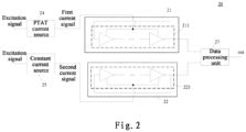
- FIG. 2 shows a schematic structural diagram of another embodiment of a circuit for temperature measurement according to the disclosure.
- a circuit 20 for temperature measurement includes a first temperature sensing circuit 21, a second temperature sensing circuit 22, a data processing unit 23, a proportional to absolute temperature (PTAT) current source 24, and a constant current source 25 as shown in FIG. 2 .
- PTAT proportional to absolute temperature
- the proportional to absolute temperature (PTAT) current source 24 refers to a current source having a proportional relation between the magnitude of an output current and an absolute temperature (in unit: kelvin).
- the current output from the PTAT current source 24 may be regarded as a PTAT current.
- An implementation circuit of the PTAT current source 24 herein may be an implementation circuit of various existing PTAT current sources.
- the PTAT current source 24 may be arranged in the integrated circuit.
- the PTAT current source 24 may be arranged in the integrated circuit in the form of a sub-circuit as a core unit of a temperature sensor. Its output current is proportional to the absolute temperature. In this way, the present environmental temperature may be reflected by the magnitude of the current output from the PTAT current source 24 through some mechanism.
- the PTAT current source 24 is configured to generate a first current signal having a magnitude that changes with temperature.
- An output end of the PTAT current source 24 is connected to an input end of the first temperature sensing circuit, so as to input the first current signal into the first temperature sensing circuit.
- the constant current source 25 may be composed of the PTAT current source and a complementary to absolute temperature (CTAT) circuit.
- CTAT complementary to absolute temperature
- the CTAT circuit is a circuit generating a negative temperature coefficient. That is, the magnitude of the current generated by the circuit is negatively correlated to temperature.
- the constant current source may be composed of the PTAT current source 24 and a CTAT circuit. For instance, the first current signal output from the PTAT current source is input into the CTAT circuit, and the CTAT circuit outputs the second current signal that does not change with temperature.
- CTAT circuits may be used as the CTAT circuit in the embodiment.
- the PTAT current source 24 outputs the first current signal that is positively correlated to temperature under the excitation of a voltage signal.
- the CTAT circuit outputs a calibration current signal that is negatively correlated to temperature and is used for calibration under excitation of the voltage signal.
- a first weight and a second weight may be assigned to the calibration current signal and the first current signal, respectively.
- the second current signal is determined according to a product of a calibration signal and the first weight and a product of the first current signal and the second weight. For instance, the sum of the product of the calibration signal and the first weight and the product of the first current signal and the second weight is regarded as the second current signal.
- a constant current signal (the second current signal) having a current that does not change with temperature may be obtained by means of the PTAT current source 24 and the CTAT circuit.
- the second temperature sensing circuit may be a replication of the first temperature sensing circuit. Specifically, the second temperature sensing circuit may have the same circuit structure as the first temperature sensing circuit. Each element used in the circuit structure of the second temperature sensing circuit may have the same element parameter as the corresponding element in the circuit structure of the first temperature sensing circuit.
- the first temperature sensing circuit 21 includes a first ring oscillator 211.
- the second temperature sensing circuit 22 includes a second ring oscillator 221.
- a signal input end of the first ring oscillator 211 is connected to the output end of the PTAT current source 24.
- a signal input end of the second ring oscillator 221 is connected to the output end of the constant current signal source 25.
- the first ring oscillator 211 and the second ring oscillator 221 may each include an odd number of phase inverters.
- the first ring oscillator 211 and the second ring oscillator 221 each include an equal number of phase inverters.
- each phase inverter in the first ring oscillator may have the same parameter as the corresponding phase inverter in the second ring oscillator.
- the parameter of the phase inverter herein may include capacitance, for example.
- the first ring oscillator 211 may generate a first oscillation current signal according to the first current signal input.
- the first oscillation current signal herein may be a first measurement signal.
- the first oscillation current signal is a first periodic pulse signal.
- the frequency of the first periodic pulse signal may be correlated to the magnitude of the first current signal.
- the second ring oscillator 221 may generate a second oscillation current signal according to the second current signal input.
- the second oscillation current signal herein may be a second measurement signal.
- the oscillation frequency of the second oscillation current signal is correlated to the second current signal.
- the second current signal may be generated by the constant current source 25.
- the signal input end of the PTAT current source 24 and the signal input end of constant current source 25 may be input with the same excitation signal.
- the PTAT current source that constitutes the constant current source may be a replication of the PTAT current source generating the first current signal.
- the constant current source may be composed of the PTAT current source generating the first current signal and a CTAT circuit. That is, in the application scenes, the second current signal may be generated after the first current signal flows through the CTAT circuit.
- the first current signal generated by the PTAT current source may be denoted as Iptat.
- a second characteristic parameter (that is, a second oscillation frequency) of the second measurement signal output from the second ring oscillator 221 under the action of the second current signal may be Fabs.
- F 2 Fabs
- Formula (4) may be subtracted from formula (3), such that a temperature measurement frequency F3 is obtained as follows:
- the temperature is determined through formula (5), such that the influence of the circuit parameters in the ring oscillators on results may be eliminated. In this way, the linearity of a test result can be improved.
- a relation curve between the temperature and temperature measurement frequency F3 may be calibrated according to formula (5), such that a value of b' is determined.
- the present temperature T may be determined according to the temperature measurement frequency F3 output from the circuit for temperature measurement.
- the PTAT current source and the constant current source are arranged in the circuit for temperature measurement, a PTAT current is input into the first ring oscillator such that the first measurement signal is obtained, and the second current signal output from the constant current source is input into the second ring oscillator such that the second measurement signal is obtained.
- the first oscillation frequency is determined according to the first measurement signal
- the second oscillation frequency is determined according to the second measurement signal.
- the temperature measurement frequency only correlated to temperature is extracted from the first oscillation frequency with the second oscillation frequency, and the temperature is determined with the temperature measurement frequency, such that a more accurate measurement result may be obtained.
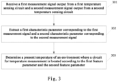
- FIG. 3 shows a schematic flow diagram of some embodiments of a method for temperature measurement according to the disclosure.
- the method for temperature measurement is configured for a data processing unit in the circuit for temperature measurement as shown in FIG. 1 .
- the circuit for temperature measurement includes a first temperature sensing circuit and a second temperature sensing circuit.
- the method for temperature measurement includes the following steps:
- Step 301 a first measurement signal output from the first temperature sensing circuit and a second measurement signal output from the second temperature sensing circuit are received.
- An input signal to the first temperature sensing circuit is the first current signal, and a magnitude of the first current signal is correlated to temperature.
- the first measurement signal is correlated to both the temperature and a circuit parameter of the first temperature sensing circuit.
- An input signal to the second temperature sensing circuit is the second current signal, and the second current signal is independent of temperature.
- the second measurement signal is correlated to a circuit parameter of the second temperature sensing circuit.
- the first temperature sensing circuit has the same corresponding circuit parameter as the second temperature sensing circuit.
- Step 302 a first characteristic parameter corresponding to the first measurement signal and a second characteristic parameter corresponding to the second measurement signal are extracted.
- Step 303 a present temperature of an environment where the circuit for temperature measurement is located is determined according to the first characteristic parameter and the second characteristic parameter.
- a part that is the same as the second characteristic parameter may be extracted from the first characteristic parameter, and the present temperature of the environment where the circuit for temperature measurement is located is determined according to a remaining part of the characteristic parameter.
- the remaining part of the characteristic parameter herein is only correlated to temperature.
- the circuit for temperature measurement includes a PTAT current source and a constant current source.
- the first temperature sensing circuit includes a first ring oscillator
- the second temperature sensing circuit includes a second ring oscillator.
- a signal input end of the first ring oscillator is connected to an output end of the PTAT current source.
- a signal input end of the second ring oscillator is connected to an output end of the constant current source.
- the first ring oscillator and the second ring oscillator each include an equal number of phase inverters.
- the first ring oscillator and the second ring oscillator each include an odd number of phase inverters.
- the second ring oscillator may be a mirror of the first ring oscillator.
- the phase inverter corresponding to the first ring oscillator has the same parameter as the phase inverter corresponding to the second ring oscillator.
- the first measurement signal may be a first periodic oscillation signal output from the first ring oscillator.
- the second measurement signal may be a second periodic oscillation signal output from the second ring oscillator.
- the first periodic oscillation signal is a periodic pulse signal.
- the second periodic oscillation signal is also a periodic pulse signal.
- Step 302 may include the following: a first oscillation frequency is extracted as the first characteristic parameter from the first measurement signal; and a second oscillation frequency is extracted as the second characteristic parameter from the second measurement signal.
- the first oscillation frequency may be correlated to temperature and a circuit parameter of the first ring oscillator.
- the second oscillation frequency is correlated to a circuit parameter of the second ring oscillator.
- a circuit parameter of the first ring oscillator is the same as a circuit parameter of the second ring oscillator.
- the first ring oscillator and the second ring oscillator each include an equal number of phase inverters.
- the first ring oscillator and the second ring oscillator each include an odd number of phase inverters.
- Step 303 further includes the following steps:
- the first current signal generated by the PTAT current source may be denoted as Iptat.
- the current signal generated by the constant current source may be denoted as Iabs.
- Iptat a ⁇ T where a is a constant and T is an absolute temperature.
- a second characteristic parameter (a second oscillation frequency) of the second measurement signal output from the second ring oscillator under the action of the second current signal may be Fabs.
- F 2 Fabs
- a relation curve between the temperature and temperature measurement frequency F3 may be calibrated according to formula (10), such that a value of b' is determined.
- the present temperature T of the environment where the circuit for temperature measurement is located may be determined according to the temperature measurement frequency output from the circuit for temperature measurement.
Landscapes
- Physics & Mathematics (AREA)
- General Physics & Mathematics (AREA)
- Measuring Temperature Or Quantity Of Heat (AREA)
Abstract
Description
- The disclosure claims the priority to
Chinese patent application No. 202110496105.0, filed on May 7, 2021 - The disclosure relates to the technical field of temperature measurement, and particularly relates to a circuit and a method for temperature measurement.
- Temperature control of a circuit is generally required. With a high-end analog-to-digital converter (ADC), a circuit for temperature measurement is large in occupied area and difficult to route. In addition, the circuit for temperature measurement often has the shortcomings of inaccuracy in measured temperature and nonlinear performance.
- The disclosed content is provided to introduce concepts in a simplified way, and the concepts will be described in detail in the following specific embodiments. The disclosed content is intended neither to identify key features or essential features of the claimed technical solution nor to limit the scope of the claimed technical solution.
- Embodiments of the disclosure provide a circuit and a method for temperature measurement.
- In a first aspect, an embodiment of the disclosure provides a circuit for temperature measurement. The circuit includes: a first temperature sensing circuit, a second temperature sensing circuit, and a data processing unit. The first temperature sensing circuit is configured to generate a first measurement signal for representing temperature according to a first current signal input, and the magnitude of the first current signal is correlated to temperature. The second temperature sensing circuit is configured to generate a second measurement signal for representing temperature according to a second current signal input, and the second current signal is independent of temperature. An output end of the first temperature sensing circuit and an output end of the second temperature sensing circuit are both connected to an input end of the data processing unit. The data processing unit is configured to determine a present temperature according to a first characteristic parameter corresponding to the first measurement signal and a second characteristic parameter corresponding to the second measurement signal. The circuit parameter of the first temperature sensing circuit is the same as the circuit parameter of the second temperature sensing circuit.
- In a second aspect, an embodiment of the disclosure provides a method for temperature measurement. The method is configured for a data processing unit in the circuit for temperature measurement according to the first aspect. The circuit for temperature measurement includes a first temperature sensing circuit and a second temperature sensing circuit. The method includes: receiving a first measurement signal output from the first temperature sensing circuit and a second measurement signal output from the second temperature sensing circuit, where the input signal to the first temperature sensing circuit is a first current signal, and the magnitude of the first current signal is correlated to temperature; and the input signal to the second temperature sensing circuit is a second current signal, and the second current signal is independent of temperature; extracting a first characteristic parameter corresponding to the first measurement signal and a second characteristic parameter corresponding to the second measurement signal; and determining a present temperature of an environment where the circuit for temperature measurement is located according to the first characteristic parameter and the second characteristic parameter.
- What is described above and other features, advantages and aspects of embodiments of the disclosure will become more obvious with reference to the following specific embodiments in conjunction with the accompanying drawings. In the drawings, the same or similar reference numerals denote the same or similar elements. It should be understood that the drawings are illustrative, and components and elements are not necessarily drawn to scale.
-
FIG. 1 is a schematic structural diagram of some embodiments of a circuit for temperature measurement according to the disclosure; -
FIG. 2 is a schematic structural diagram of some other embodiments of a circuit for temperature measurement according to the disclosure; and -
FIG. 3 is a schematic flow diagram of some embodiments of a method for temperature measurement according to the disclosure. - Embodiments of the disclosure will be described in more detail below with reference to the accompanying drawings. Although some embodiments of the disclosure are shown in the accompanying drawings, it should be understood that the disclosure may be implemented in various forms and should not be construed as limiting to the embodiments illustrated herein. Rather, the embodiments are provided for a more thorough and complete understanding of the disclosure. It should be understood that the drawings and the embodiments of the disclosure are only for illustrative purposes, instead of limiting the protection scope of the disclosure.
- It should be understood that all steps described in method embodiments of the disclosure may be executed in a different order and/or in parallel. Further, the method embodiments may include additional steps and/or omit execution of the illustrated steps, which do not limit the scope of the disclosure.
- The terms "include" and "comprise" used herein and their variations are open-ended, that is, "including but not limited to" and "comprising but not limited to". The term "on the basis of/based on" means "at least partly on the basis of/at least partly based on". The term "an embodiment" means "at least one embodiment". The term "another embodiment" means "at least another embodiment". The term "some embodiments" means "at least some embodiments". Related definitions of other terms will be given in the following description.
- It should be noted that concepts such as "first" and "second" mentioned in the disclosure are only used to distinguish different apparatuses, modules or units, and are not used to limit an order or interdependence of functions executed by the apparatuses, modules or units.
- It should be noted that modification with "a", "an" or "a plurality of" mentioned in the disclosure is illustrative rather than limitative, and should be understood by those skilled in the art as "one or more" unless explicitly stated otherwise in the context.
- Names of messages or information exchanged between a plurality of apparatuses in the embodiment of the disclosure are only for illustrative purposes, instead of limiting the scope of the messages or information.
- Reference is made to
FIG. 1 , which shows a schematic structural diagram of some embodiments of a circuit for temperature measurement according to the disclosure. As shown inFIG. 1 , thecircuit 10 for temperature measurement includes: - a first
temperature sensing circuit 11, a secondtemperature sensing circuit 12, and adata processing unit 13. - The first
temperature sensing circuit 11 is configured to generate a first measurement signal for representing temperature according to a first current signal input. The magnitude of the first current signal is correlated to temperature. The first measurement signal is correlated to temperature and a circuit parameter of the first temperature sensing circuit. - The second
temperature sensing circuit 12 is configured to generate a second measurement signal configured for representing temperature according to a second current signal input. The second current signal is independent of temperature. The second measurement signal is correlated to a circuit parameter of the second temperature sensing circuit. - An output end of the first
temperature sensing circuit 11 and an output end of the secondtemperature sensing circuit 12 are both connected to an input end of thedata processing unit 13. - The
data processing unit 13 is configured to determine a present temperature according to a first characteristic parameter corresponding to the first measurement signal and a second characteristic parameter corresponding to the second measurement signal. The circuit parameter of the first temperature sensing circuit is the same as the circuit parameter of the second temperature sensing circuit. - In some application scenes, the circuit for temperature measurement may be applied to the design of an integrated circuit, so as to detect a temperature of the integrated circuit during work. In the application scenes, the circuit for temperature measurement may be a circuit module for temperature detection that is fixedly arranged in the above-described integrated circuit.
- The first measurement signal may be a first periodic oscillation signal. For instance, the first characteristic parameter may be a first frequency of the first periodic oscillation signal.
- The second measurement signal may be a second periodic oscillation signal. For instance, the second characteristic parameter may be a second frequency of the second periodic oscillation signal.
- The first frequency may be correlated to the present temperature and the circuit parameter of the first temperature sensing circuit, and the second frequency may be correlated to the circuit parameter of the second temperature sensing circuit.
- The circuit parameter of the first temperature sensing circuit is the same as the circuit parameter of the second temperature sensing circuit. For instance, the same elements required by the first temperature sensing circuit and the second temperature sensing circuit may be manufactured through the same manufacturing process.
- The circuit parameter of the first
temperature sensing circuit 11 is the same as the circuit parameter of the secondtemperature sensing circuit 12. Thus, for the current signals input, an output signal generated by the circuit parameter of the first temperature sensing circuit for a first current signal input to the first temperature sensing may be approximately considered to be the same as an output signal generated by the circuit parameter of the second temperature sensing circuit for a second current signal input to the second temperature sensing circuit. - The output signal generated by the circuit parameter of the first temperature sensing circuit for a circuit signal may be removed from the first measurement signal with the second measurement signal generated by the second temperature sensing circuit for the second current signal. The remaining part of the first measurement signal is only correlated to the first current signal. The first current signal is a signal correlated to temperature. Therefore, the remaining part of the first measurement signal may also be regarded as only correlated to temperature. The temperature of an environment where the circuit for temperature measurement is located may be determined according to the remaining part of the first measurement signal.
- In the circuit for temperature measurement according to the embodiment, the first temperature sensing circuit and the second temperature sensing circuit that have the same circuit parameter are arranged, and the first current signal and the second current signal are input into the first temperature sensing circuit and the second temperature sensing circuit, respectively. The magnitude of the first current signal is correlated to temperature, and the magnitude of the second current signal is independent of temperature. Influence of the circuit parameter of the first temperature sensing circuit in the first measurement signal output from the first temperature sensing circuit may be eliminated with the second measurement signal output from the second temperature sensing circuit, such that linearity of the measurement result of the circuit for temperature measurement can be improved according to the temperature obtained by the circuit for temperature measurement, and meanwhile, the accuracy of the temperature measurement result can be enhanced.
- Reference is made to
FIG. 2 , which shows a schematic structural diagram of another embodiment of a circuit for temperature measurement according to the disclosure. - Compared with the embodiment shown in
FIG. 1 , a circuit 20 for temperature measurement includes a firsttemperature sensing circuit 21, a second temperature sensing circuit 22, adata processing unit 23, a proportional to absolute temperature (PTAT)current source 24, and a constantcurrent source 25 as shown inFIG. 2 . - The proportional to absolute temperature (PTAT)
current source 24 refers to a current source having a proportional relation between the magnitude of an output current and an absolute temperature (in unit: kelvin). - That is, a relation between the magnitude of a current I (in unit: ampere) output from the PTAT
current source 24 and a temperature T (in unit: kelvin) of the environment where the PTATcurrent source 24 is located satisfies I=A×T (A is a fixed constant). The current output from the PTATcurrent source 24 may be regarded as a PTAT current. An implementation circuit of the PTATcurrent source 24 herein may be an implementation circuit of various existing PTAT current sources. - In some application scenes, when the circuit for temperature measurement is applied to the field of measuring an integrated circuit, the PTAT
current source 24 may be arranged in the integrated circuit. The PTATcurrent source 24 may be arranged in the integrated circuit in the form of a sub-circuit as a core unit of a temperature sensor. Its output current is proportional to the absolute temperature. In this way, the present environmental temperature may be reflected by the magnitude of the current output from the PTATcurrent source 24 through some mechanism. - The PTAT
current source 24 is configured to generate a first current signal having a magnitude that changes with temperature. - An output end of the PTAT
current source 24 is connected to an input end of the first temperature sensing circuit, so as to input the first current signal into the first temperature sensing circuit. - The constant
current source 25 may be composed of the PTAT current source and a complementary to absolute temperature (CTAT) circuit. The CTAT circuit is a circuit generating a negative temperature coefficient. That is, the magnitude of the current generated by the circuit is negatively correlated to temperature. In some application scenes, the constant current source may be composed of the PTATcurrent source 24 and a CTAT circuit. For instance, the first current signal output from the PTAT current source is input into the CTAT circuit, and the CTAT circuit outputs the second current signal that does not change with temperature. - Various existing CTAT implementation circuits may be used as the CTAT circuit in the embodiment.
- The PTAT
current source 24 outputs the first current signal that is positively correlated to temperature under the excitation of a voltage signal. - The CTAT circuit outputs a calibration current signal that is negatively correlated to temperature and is used for calibration under excitation of the voltage signal.
- A first weight and a second weight may be assigned to the calibration current signal and the first current signal, respectively. The second current signal is determined according to a product of a calibration signal and the first weight and a product of the first current signal and the second weight. For instance, the sum of the product of the calibration signal and the first weight and the product of the first current signal and the second weight is regarded as the second current signal.
- A constant current signal (the second current signal) having a current that does not change with temperature may be obtained by means of the PTAT
current source 24 and the CTAT circuit. - The second temperature sensing circuit may be a replication of the first temperature sensing circuit. Specifically, the second temperature sensing circuit may have the same circuit structure as the first temperature sensing circuit. Each element used in the circuit structure of the second temperature sensing circuit may have the same element parameter as the corresponding element in the circuit structure of the first temperature sensing circuit.
- In the embodiment, the first
temperature sensing circuit 21 includes afirst ring oscillator 211. The second temperature sensing circuit 22 includes asecond ring oscillator 221. A signal input end of thefirst ring oscillator 211 is connected to the output end of the PTATcurrent source 24. A signal input end of thesecond ring oscillator 221 is connected to the output end of the constantcurrent signal source 25. - The
first ring oscillator 211 and thesecond ring oscillator 221 may each include an odd number of phase inverters. Thefirst ring oscillator 211 and thesecond ring oscillator 221 each include an equal number of phase inverters. Further, each phase inverter in the first ring oscillator may have the same parameter as the corresponding phase inverter in the second ring oscillator. The parameter of the phase inverter herein may include capacitance, for example. - The
first ring oscillator 211 may generate a first oscillation current signal according to the first current signal input. The first oscillation current signal herein may be a first measurement signal. The first oscillation current signal is a first periodic pulse signal. The frequency of the first periodic pulse signal may be correlated to the magnitude of the first current signal. - The
second ring oscillator 221 may generate a second oscillation current signal according to the second current signal input. The second oscillation current signal herein may be a second measurement signal. The oscillation frequency of the second oscillation current signal is correlated to the second current signal. - The second current signal may be generated by the constant
current source 25. In some application scenes, the signal input end of the PTATcurrent source 24 and the signal input end of constantcurrent source 25 may be input with the same excitation signal. In some other application scenes, the PTAT current source that constitutes the constant current source may be a replication of the PTAT current source generating the first current signal. - In some other application scenes, the constant current source may be composed of the PTAT current source generating the first current signal and a CTAT circuit. That is, in the application scenes, the second current signal may be generated after the first current signal flows through the CTAT circuit.
- In the above two application scenes, relations between the second current signal and the first current signal are as follows:
- The first current signal generated by the PTAT current source may be denoted as Iptat. The current signal generated by the constant current source may be denoted as labs.

a is a constant and T is an absolute temperature. - A relation between the second current signal and the first current signal may be indicated by the following formula:

ΔIptat is a difference between Iptat and labs. Since Iabs does not change with temperature, and Iptat changes with temperature, ΔIptat changes with temperature. - A first characteristic parameter (that is, a first oscillation frequency) of the first measurement signal output from the
first ring oscillator 211 under the action of the first current signal may be:

b herein is a constant. - A second characteristic parameter (that is, a second oscillation frequency) of the second measurement signal output from the
second ring oscillator 221 under the action of the second current signal may be Fabs.
- Formula (4) may be subtracted from formula (3), such that a temperature measurement frequency F3 is obtained as follows:

the temperature is determined through formula (5), such that the influence of the circuit parameters in the ring oscillators on results may be eliminated. In this way, the linearity of a test result can be improved. - In practice, a relation curve between the temperature and temperature measurement frequency F3 may be calibrated according to formula (5), such that a value of b' is determined. During an actual measurement of the temperature, the present temperature T may be determined according to the temperature measurement frequency F3 output from the circuit for temperature measurement.
- In the circuit for temperature measurement according to the embodiment, the PTAT current source and the constant current source are arranged in the circuit for temperature measurement, a PTAT current is input into the first ring oscillator such that the first measurement signal is obtained, and the second current signal output from the constant current source is input into the second ring oscillator such that the second measurement signal is obtained. The first oscillation frequency is determined according to the first measurement signal, and the second oscillation frequency is determined according to the second measurement signal. The temperature measurement frequency only correlated to temperature is extracted from the first oscillation frequency with the second oscillation frequency, and the temperature is determined with the temperature measurement frequency, such that a more accurate measurement result may be obtained.
-
FIG. 3 shows a schematic flow diagram of some embodiments of a method for temperature measurement according to the disclosure. The method for temperature measurement is configured for a data processing unit in the circuit for temperature measurement as shown inFIG. 1 . - The circuit for temperature measurement includes a first temperature sensing circuit and a second temperature sensing circuit. The method for temperature measurement includes the following steps:
-
Step 301, a first measurement signal output from the first temperature sensing circuit and a second measurement signal output from the second temperature sensing circuit are received. - An input signal to the first temperature sensing circuit is the first current signal, and a magnitude of the first current signal is correlated to temperature. The first measurement signal is correlated to both the temperature and a circuit parameter of the first temperature sensing circuit.
- An input signal to the second temperature sensing circuit is the second current signal, and the second current signal is independent of temperature. The second measurement signal is correlated to a circuit parameter of the second temperature sensing circuit.
- The first temperature sensing circuit has the same corresponding circuit parameter as the second temperature sensing circuit.
-
Step 302, a first characteristic parameter corresponding to the first measurement signal and a second characteristic parameter corresponding to the second measurement signal are extracted. -
Step 303, a present temperature of an environment where the circuit for temperature measurement is located is determined according to the first characteristic parameter and the second characteristic parameter. - Specifically, a part that is the same as the second characteristic parameter may be extracted from the first characteristic parameter, and the present temperature of the environment where the circuit for temperature measurement is located is determined according to a remaining part of the characteristic parameter.
- The remaining part of the characteristic parameter herein is only correlated to temperature.
- In some application scenes, the circuit for temperature measurement includes a PTAT current source and a constant current source. The first temperature sensing circuit includes a first ring oscillator, and the second temperature sensing circuit includes a second ring oscillator. A signal input end of the first ring oscillator is connected to an output end of the PTAT current source. A signal input end of the second ring oscillator is connected to an output end of the constant current source.
- The first ring oscillator and the second ring oscillator each include an equal number of phase inverters. The first ring oscillator and the second ring oscillator each include an odd number of phase inverters. The second ring oscillator may be a mirror of the first ring oscillator.
- The phase inverter corresponding to the first ring oscillator has the same parameter as the phase inverter corresponding to the second ring oscillator.
- The first measurement signal may be a first periodic oscillation signal output from the first ring oscillator. The second measurement signal may be a second periodic oscillation signal output from the second ring oscillator. The first periodic oscillation signal is a periodic pulse signal. The second periodic oscillation signal is also a periodic pulse signal. Step 302 may include the following: a first oscillation frequency is extracted as the first characteristic parameter from the first measurement signal; and a second oscillation frequency is extracted as the second characteristic parameter from the second measurement signal.
- The first oscillation frequency may be correlated to temperature and a circuit parameter of the first ring oscillator.
- The second oscillation frequency is correlated to a circuit parameter of the second ring oscillator.
- A circuit parameter of the first ring oscillator is the same as a circuit parameter of the second ring oscillator. The first ring oscillator and the second ring oscillator each include an equal number of phase inverters. The first ring oscillator and the second ring oscillator each include an odd number of phase inverters.
- In the application scenes,
Step 303 further includes the following steps: - first, a part of characteristic parameters only correlated to temperature is extracted from the first characteristic parameter with the second characteristic parameter; and
- then, the present temperature is determined according to the part of characteristic parameters only correlated to temperature.
- Specifically, the first current signal generated by the PTAT current source may be denoted as Iptat. The current signal generated by the constant current source may be denoted as Iabs.

a is a constant and T is an absolute temperature. - A relation between the second current signal and the first current signal may be indicated by the following formula:

ΔIptat is a difference between Iptat and Iabs. Since Iabs does not change with temperature, and Iptat changes with temperature, ΔIptat changes with temperature. - A first characteristic parameter (a first oscillation frequency) of the first measurement signal output from the first ring oscillator under the action of the first current signal may be:

b herein is a constant. - A second characteristic parameter (a second oscillation frequency) of the second measurement signal output from the second ring oscillator under the action of the second current signal may be Fabs.

- Formula (9) may be subtracted from formula (8), such that a temperature measurement frequency F3 is obtained as follows:

the temperature is determined through formula (10), such that the influence of the circuit parameters in the ring oscillators on results may be eliminated. In this way, the linearity of a test result can be improved. - In practice, a relation curve between the temperature and temperature measurement frequency F3 may be calibrated according to formula (10), such that a value of b' is determined. During an actual measurement of the temperature, the present temperature T of the environment where the circuit for temperature measurement is located may be determined according to the temperature measurement frequency output from the circuit for temperature measurement.
- What are described above are merely illustrative of preferred embodiments of the disclosure and principles of the technology employed. Those skilled in the art should understand that the disclosure scope of the disclosure is not limited to the technical solution formed by a specific combination of the technical features described above, and should further cover other technical solutions formed by any combination of the technical features described above or their equivalent features without departing from the disclosed concept, for instance, the technical solution formed by replacing the features with the technical features having similar functions disclosed in (but not limited to) the disclosure or vice versa.
- Further, although operations are depicted in a particular order, it should be understood that the operations are not required to be executed in the particular order shown or in a sequential order. In some cases, multitasking and parallel processing may be advantageous. Likewise, although several specific implementation details are included in the above discussion, the details should not be construed as limiting the scope of the disclosure. Some features described in the context of separate embodiments may also be implemented in combination in a single embodiment. On the contrary, various features described in the context of a single embodiment may also be implemented in a plurality of embodiments separately or in any suitable sub-combination manner.
- Although the subject is described in languages of specific structural features and/or methodological logic actions, it should be understood that the subject defined in the appended claims is not necessarily limited to the specific features or actions described above. On the contrary, the specific features and actions described above are merely illustrative forms for implementing the claims.
Claims (11)
- A circuit for temperature measurement, comprising: a first temperature sensing circuit, a second temperature sensing circuit, and a data processing unit, wherein:the first temperature sensing circuit is configured to generate a first measurement signal for representing temperature according to a first current signal input, and a magnitude of the first current signal is correlated to temperature;the second temperature sensing circuit is configured to generate a second measurement signal for representing temperature according to a second current signal input, and the second current signal is independent of temperature;an output end of the first temperature sensing circuit and an output end of the second temperature sensing circuit are both connected to an input end of the data processing unit; andthe data processing unit is configured to determine a present temperature according to a first characteristic parameter corresponding to the first measurement signal and a second characteristic parameter corresponding to the second measurement signal, whereina circuit parameter of the first temperature sensing circuit is the same as a circuit parameter of the second temperature sensing circuit.
- The circuit for temperature measurement according to claim 1, wherein the first measurement signal is correlated to temperature and the circuit parameter of the first temperature sensing circuit; and
the second measurement signal is correlated to the circuit parameter of the second temperature sensing circuit. - The circuit for temperature measurement according to claim 1, the circuit for temperature measurement further comprising a proportional to absolute temperature (PTAT) current source and a constant current source, whereinthe PTAT current source is configured to generate the first current signal having a magnitude that changes with temperature; the constant current source is configured to generate a second current source having a constant magnitude;an output end of the PTAT current source is connected to an input end of the first temperature sensing circuit; andan output end of the constant current source is connected to an input end of the second temperature sensing circuit.
- The circuit for temperature measurement according to claim 3, wherein the constant current source is composed of the PTAT current source and complementary to absolute temperature circuit.
- The circuit for temperature measurement according to claim 3, wherein the first temperature sensing circuit comprises a first ring oscillator, and the second temperature sensing circuit comprises a second ring oscillator;a signal input end of the first ring oscillator is connected to the output end of the PTAT current source; anda signal input end of the second ring oscillator is connected to the output end of the constant current source.
- The circuit for temperature measurement according to claim 5, wherein the first measurement signal is a first periodic oscillation signal generated by the first ring oscillator according to the first current signal;the second measurement signal is a second periodic oscillation signal generated by the second ring oscillator according to the second current signal; the first characteristic parameter is a first oscillation frequency, and the second characteristic parameter is a second oscillation frequency; andthe data processing unit is configured to determine the present temperature according to a first oscillation frequency of the first periodic oscillation signal and a second oscillation frequency of the second periodic oscillation signal.
- The circuit for temperature measurement according to claim 5, wherein the first ring oscillator and the second ring oscillator each comprise an odd number of phase inverters.
- The circuit for temperature measurement according to claim 7, wherein the first ring oscillator and the second ring oscillator each comprise an equal number of phase inverters.
- The circuit for temperature measurement according to claim 1, wherein the second temperature sensing circuit is a mirror circuit of the first temperature sensing circuit.
- A method for temperature measurement, being configured for a data processing unit in the circuit for temperature measurement according to any one of claims 1-9, wherein the circuit for temperature measurement comprises a first temperature sensing circuit and a second temperature sensing circuit, and the method comprises:receiving a first measurement signal output from the first temperature sensing circuit and a second measurement signal output from the second temperature sensing circuit, wherein an input signal to the first temperature sensing circuit is a first current signal, and a magnitude of the first current signal is correlated to temperature; and an input signal to the second temperature sensing circuit is a second current signal, and the second current signal is independent of temperature;extracting a first characteristic parameter corresponding to the first measurement signal and a second characteristic parameter corresponding to the second measurement signal; anddetermining a present temperature of an environment where the circuit for temperature measurement is located according to the first characteristic parameter and the second characteristic parameter.
- The method according to claim 10, wherein the circuit for temperature measurement comprises a proportional to absolute temperature (PTAT) current source and a constant current source; the first temperature sensing circuit comprises a first ring oscillator, and the second temperature sensing circuit comprises a second ring oscillator; a signal input end of the first ring oscillator is connected to an output end of the PTAT current source; a signal input end of the second ring oscillator is connected to an output end of the constant current source; the first measurement signal is a first periodic oscillation signal, and the second measurement signal is a second periodic oscillation signal;
extracting the first characteristic parameter corresponding to the first measurement signal and the second characteristic parameter corresponding to the second measurement signal comprises:extracting a first oscillation frequency as the first characteristic parameter from the first periodic oscillation signal and a second oscillation frequency as the second characteristic parameter from the second periodic oscillation signal; anddetermining the present temperature of the environment where the circuit for temperature measurement is located according to the first characteristic parameter and the second characteristic parameter comprises:extracting part of characteristic parameters only correlated to temperature from the first characteristic parameter according to the second characteristic parameter; anddetermining the present temperature according to the part of characteristic parameters only correlated to temperature.
Applications Claiming Priority (2)
| Application Number | Priority Date | Filing Date | Title |
|---|---|---|---|
| CN202110496105.0A CN115307756A (en) | 2021-05-07 | 2021-05-07 | Temperature measurement circuit and method |
| PCT/SG2022/050271 WO2022235215A1 (en) | 2021-05-07 | 2022-05-04 | Temperature measurement circuit and method |
Publications (4)
| Publication Number | Publication Date |
|---|---|
| EP4321848A1 true EP4321848A1 (en) | 2024-02-14 |
| EP4321848A4 EP4321848A4 (en) | 2024-10-09 |
| EP4321848C0 EP4321848C0 (en) | 2025-11-12 |
| EP4321848B1 EP4321848B1 (en) | 2025-11-12 |
Family
ID=83854295
Family Applications (1)
| Application Number | Title | Priority Date | Filing Date |
|---|---|---|---|
| EP22799220.3A Active EP4321848B1 (en) | 2021-05-07 | 2022-05-04 | Temperature measurement circuit and method |
Country Status (4)
| Country | Link |
|---|---|
| US (1) | US12339175B2 (en) |
| EP (1) | EP4321848B1 (en) |
| CN (1) | CN115307756A (en) |
| WO (1) | WO2022235215A1 (en) |
Families Citing this family (2)
| Publication number | Priority date | Publication date | Assignee | Title |
|---|---|---|---|---|
| FR3116604B1 (en) * | 2020-11-24 | 2022-10-14 | St Microelectronics Rousset | Method for calibrating a ring oscillator temperature sensor |
| US12436045B2 (en) * | 2022-03-17 | 2025-10-07 | Steradian Semiconductors Private Limited | High accuracy on-chip temperature sensor system and method thereof |
Family Cites Families (30)
| Publication number | Priority date | Publication date | Assignee | Title |
|---|---|---|---|---|
| US5068595A (en) * | 1990-09-20 | 1991-11-26 | Delco Electronics Corporation | Adjustable temperature dependent current generator |
| US5774013A (en) * | 1995-11-30 | 1998-06-30 | Rockwell Semiconductor Systems, Inc. | Dual source for constant and PTAT current |
| US5899570A (en) * | 1997-03-28 | 1999-05-04 | Microchip Technology Incorporated | Time-based temperature sensor system and method therefor |
| JP3866545B2 (en) * | 2000-08-04 | 2007-01-10 | Necエレクトロニクス株式会社 | Timer circuit and semiconductor memory device incorporating the timer circuit |
| TW544680B (en) * | 2000-08-04 | 2003-08-01 | Nec Electronics Corp | Timer circuit and semiconductor memory device integrated with the timer circuit |
| FR2874259A1 (en) | 2004-08-12 | 2006-02-17 | St Microelectronics Sa | ELECTRONIC CIRCUIT EQUIPPED FOR EVALUATING ITS TEMPERATURE, METHOD OF EVALUATING TEMPERATURE, AND APPLICATIONS |
| US7225099B1 (en) | 2005-02-10 | 2007-05-29 | Xilinx, Inc. | Apparatus and method for temperature measurement using a bandgap voltage reference |
| KR100656430B1 (en) * | 2005-11-09 | 2006-12-11 | 주식회사 하이닉스반도체 | Temperature detection device |
| KR100800470B1 (en) * | 2006-01-11 | 2008-02-01 | 삼성전자주식회사 | Temperature Sensor Implemented as Ring Oscillator and Temperature Detection Method Using the Same |
| US7331708B2 (en) * | 2006-02-23 | 2008-02-19 | National Semiconductor Corporation | Frequency ratio digitizing temperature sensor with linearity correction |
| KR100913974B1 (en) * | 2006-02-23 | 2009-08-25 | 내셔널 세미콘덕터 코포레이션 | Frequency ratio digitizing temperature sensor with linearity correction |
| CN101109662B (en) | 2006-07-17 | 2010-09-29 | 梅特勒-托利多仪器(上海)有限公司 | A thermal resistance temperature measurement circuit |
| TWI314986B (en) | 2007-01-05 | 2009-09-21 | Ite Tech Inc | Transistor circuit with eliminating effect of parameter and temperature sensing apparatus using the same |
| JP5155717B2 (en) * | 2007-04-02 | 2013-03-06 | 高麗大学産学協力団 | Temperature measuring apparatus and method using oscillation circuit |
| TW200844415A (en) | 2007-05-15 | 2008-11-16 | Winbond Electronics Corp | Transistor circuit with estimating parameter error and temperature sensing apparatus using the same |
| US7961033B2 (en) * | 2008-09-19 | 2011-06-14 | Cavium Networks, Inc. | DLL-based temperature sensor |
| WO2011021276A1 (en) * | 2009-08-18 | 2011-02-24 | 富士通株式会社 | Temperature detection device, information processing equipment and method for controlling temperature detection device |
| EP2295944A2 (en) * | 2009-09-09 | 2011-03-16 | Nxp B.V. | Temperature sensor |
| TWI470196B (en) * | 2010-12-03 | 2015-01-21 | Pixart Imaging Inc | Temperature sensing apparatus and method using the same |
| KR101298301B1 (en) * | 2011-09-23 | 2013-08-20 | 삼성전기주식회사 | Device for measuring temperature |
| KR20130070953A (en) * | 2011-12-20 | 2013-06-28 | 한국전자통신연구원 | Oscillator-based digital temperature sensor insensitive to process changes |
| US9234804B2 (en) * | 2011-12-29 | 2016-01-12 | Stmicroelectronics Asia Pacific Pte Ltd | Temperature sensor for image sensors |
| US9810583B2 (en) * | 2013-05-17 | 2017-11-07 | Analog Devices, Inc. | Encoder circuit with feedback DAC |
| US9261415B1 (en) * | 2014-09-22 | 2016-02-16 | Infineon Technologies Ag | System and method for temperature sensing |
| US9970830B2 (en) * | 2016-06-14 | 2018-05-15 | International Business Machines Corporation | Approach to measuring strain effects using ring oscillators |
| US10288494B2 (en) * | 2016-11-30 | 2019-05-14 | Taiwan Semiconductor Manufacturing Co., Ltd. | MTJ-based temperature-sensing device |
| US10473530B2 (en) * | 2017-08-18 | 2019-11-12 | Qualcomm Incorporated | Apparatus and method for generating temperature-indicating signal using correlated-oscillators |
| CN109060162A (en) * | 2018-06-29 | 2018-12-21 | 长江存储科技有限责任公司 | Temperature Sensor |
| US10763830B2 (en) * | 2018-11-09 | 2020-09-01 | Nxp B.V. | Current controlled oscillator |
| US11532357B2 (en) * | 2021-01-15 | 2022-12-20 | Taiwan Semiconductor Manufacturing Company, Ltd. | Memory cell with temperature modulated read voltage |
-
2021
- 2021-05-07 CN CN202110496105.0A patent/CN115307756A/en active Pending
-
2022
- 2022-05-04 EP EP22799220.3A patent/EP4321848B1/en active Active
- 2022-05-04 WO PCT/SG2022/050271 patent/WO2022235215A1/en not_active Ceased
- 2022-05-04 US US17/736,157 patent/US12339175B2/en active Active
Also Published As
| Publication number | Publication date |
|---|---|
| US12339175B2 (en) | 2025-06-24 |
| WO2022235215A1 (en) | 2022-11-10 |
| US20220357215A1 (en) | 2022-11-10 |
| CN115307756A (en) | 2022-11-08 |
| EP4321848C0 (en) | 2025-11-12 |
| EP4321848B1 (en) | 2025-11-12 |
| EP4321848A4 (en) | 2024-10-09 |
Similar Documents
| Publication | Publication Date | Title |
|---|---|---|
| Beckwith | Mechanical measurements | |
| Rabinovich et al. | Evaluating measurement accuracy | |
| Moffat | Describing the uncertainties in experimental results | |
| EP4321848B1 (en) | Temperature measurement circuit and method | |
| Giordani et al. | Measurement, models, and uncertainty | |
| Tal | Individuating quantities: E. Tal | |
| JPH04320982A (en) | Semiconductor electronic circuit | |
| CN109781341B (en) | Data calibration method and device for air pressure sensor | |
| Vasilevskyi et al. | The method of translation additive and multiplicative error in the instrumental component of the measurement uncertainty | |
| CN114636484B (en) | Digital temperature sensor, chip temperature detection system and chip temperature detection method | |
| Cui et al. | On quantum reliability characterizing systematic errors in quantum sensing | |
| CN112379318B (en) | Coefficient calibration method, device, equipment and medium for power range detector | |
| TWI841958B (en) | Temperature measurement circuit and method | |
| EP3763048B1 (en) | Measurement apparatus | |
| KR101298301B1 (en) | Device for measuring temperature | |
| Giordani et al. | On theory dependence of truth in measurement | |
| CN114256052A (en) | Pulse delay device, method and time-of-flight mass spectrometer comprising pulse delay device | |
| CN116182926A (en) | On-site detection device and clock detection method | |
| Zheng et al. | A frequency calculation and temperature compensation system for quartz resonant accelerometer sensors | |
| Wang et al. | Reliability evaluation of high precision fiber optic gyroscope based on temperature and humidity dual stress Peck model | |
| US20250362184A1 (en) | Temperature sensor using a controlled oscillator | |
| Boumans | Truth versus precision | |
| US10648867B2 (en) | Magnetic temperature sensor | |
| US8428911B2 (en) | Testing method and computer device and computer testing system using thereof | |
| Bartiromo et al. | Uncertainty in electrical measurements |
Legal Events
| Date | Code | Title | Description |
|---|---|---|---|
| STAA | Information on the status of an ep patent application or granted ep patent |
Free format text: STATUS: THE INTERNATIONAL PUBLICATION HAS BEEN MADE |
|
| PUAI | Public reference made under article 153(3) epc to a published international application that has entered the european phase |
Free format text: ORIGINAL CODE: 0009012 |
|
| STAA | Information on the status of an ep patent application or granted ep patent |
Free format text: STATUS: REQUEST FOR EXAMINATION WAS MADE |
|
| 17P | Request for examination filed |
Effective date: 20231106 |
|
| AK | Designated contracting states |
Kind code of ref document: A1 Designated state(s): AL AT BE BG CH CY CZ DE DK EE ES FI FR GB GR HR HU IE IS IT LI LT LU LV MC MK MT NL NO PL PT RO RS SE SI SK SM TR |
|
| DAV | Request for validation of the european patent (deleted) | ||
| DAX | Request for extension of the european patent (deleted) | ||
| REG | Reference to a national code |
Ref country code: DE Ref legal event code: R079 Free format text: PREVIOUS MAIN CLASS: G01K0007160000 Ipc: G01K0007010000 Ref country code: DE Ref legal event code: R079 Ref document number: 602022024978 Country of ref document: DE Free format text: PREVIOUS MAIN CLASS: G01K0007160000 Ipc: G01K0007010000 |
|
| A4 | Supplementary search report drawn up and despatched |
Effective date: 20240910 |
|
| RIC1 | Information provided on ipc code assigned before grant |
Ipc: G01K 1/20 20060101ALI20240904BHEP Ipc: G01K 7/16 20060101ALI20240904BHEP Ipc: G01K 7/01 20060101AFI20240904BHEP |
|
| GRAP | Despatch of communication of intention to grant a patent |
Free format text: ORIGINAL CODE: EPIDOSNIGR1 |
|
| STAA | Information on the status of an ep patent application or granted ep patent |
Free format text: STATUS: GRANT OF PATENT IS INTENDED |
|
| INTG | Intention to grant announced |
Effective date: 20250603 |
|
| GRAS | Grant fee paid |
Free format text: ORIGINAL CODE: EPIDOSNIGR3 |
|
| GRAA | (expected) grant |
Free format text: ORIGINAL CODE: 0009210 |
|
| STAA | Information on the status of an ep patent application or granted ep patent |
Free format text: STATUS: THE PATENT HAS BEEN GRANTED |
|
| AK | Designated contracting states |
Kind code of ref document: B1 Designated state(s): AL AT BE BG CH CY CZ DE DK EE ES FI FR GB GR HR HU IE IS IT LI LT LU LV MC MK MT NL NO PL PT RO RS SE SI SK SM TR |
|
| REG | Reference to a national code |
Ref country code: CH Ref legal event code: F10 Free format text: ST27 STATUS EVENT CODE: U-0-0-F10-F00 (AS PROVIDED BY THE NATIONAL OFFICE) Effective date: 20251112 Ref country code: GB Ref legal event code: FG4D |
|
| REG | Reference to a national code |
Ref country code: IE Ref legal event code: FG4D |
|
| REG | Reference to a national code |
Ref country code: DE Ref legal event code: R096 Ref document number: 602022024978 Country of ref document: DE |
|
| U01 | Request for unitary effect filed |
Effective date: 20251209 |
|
| U07 | Unitary effect registered |
Designated state(s): AT BE BG DE DK EE FI FR IT LT LU LV MT NL PT RO SE SI Effective date: 20251215 |
|
| PGFP | Annual fee paid to national office [announced via postgrant information from national office to epo] |
Ref country code: GB Payment date: 20260302 Year of fee payment: 5 |
|
| PG25 | Lapsed in a contracting state [announced via postgrant information from national office to epo] |
Ref country code: ES Free format text: LAPSE BECAUSE OF FAILURE TO SUBMIT A TRANSLATION OF THE DESCRIPTION OR TO PAY THE FEE WITHIN THE PRESCRIBED TIME-LIMIT Effective date: 20251112 |
|
| PG25 | Lapsed in a contracting state [announced via postgrant information from national office to epo] |
Ref country code: NO Free format text: LAPSE BECAUSE OF FAILURE TO SUBMIT A TRANSLATION OF THE DESCRIPTION OR TO PAY THE FEE WITHIN THE PRESCRIBED TIME-LIMIT Effective date: 20260212 |
|
| PG25 | Lapsed in a contracting state [announced via postgrant information from national office to epo] |
Ref country code: HR Free format text: LAPSE BECAUSE OF FAILURE TO SUBMIT A TRANSLATION OF THE DESCRIPTION OR TO PAY THE FEE WITHIN THE PRESCRIBED TIME-LIMIT Effective date: 20251112 |
|
| PG25 | Lapsed in a contracting state [announced via postgrant information from national office to epo] |
Ref country code: RS Free format text: LAPSE BECAUSE OF FAILURE TO SUBMIT A TRANSLATION OF THE DESCRIPTION OR TO PAY THE FEE WITHIN THE PRESCRIBED TIME-LIMIT Effective date: 20260212 |
|
| PG25 | Lapsed in a contracting state [announced via postgrant information from national office to epo] |
Ref country code: IS Free format text: LAPSE BECAUSE OF FAILURE TO SUBMIT A TRANSLATION OF THE DESCRIPTION OR TO PAY THE FEE WITHIN THE PRESCRIBED TIME-LIMIT Effective date: 20260312 |
|
| PG25 | Lapsed in a contracting state [announced via postgrant information from national office to epo] |
Ref country code: PL Free format text: LAPSE BECAUSE OF FAILURE TO SUBMIT A TRANSLATION OF THE DESCRIPTION OR TO PAY THE FEE WITHIN THE PRESCRIBED TIME-LIMIT Effective date: 20251112 |
|
| U1N | Appointed representative for the unitary patent procedure changed after the registration of the unitary effect |
Representative=s name: MARKS & CLERK LLP; GB |
|
| U20 | Renewal fee for the european patent with unitary effect paid |
Year of fee payment: 5 Effective date: 20260408 |