EP4321342A1 - Fluid fillable cartridge, method for preventing contamination, method for making adhesive sealing tape - Google Patents
Fluid fillable cartridge, method for preventing contamination, method for making adhesive sealing tape Download PDFInfo
- Publication number
- EP4321342A1 EP4321342A1 EP23185797.0A EP23185797A EP4321342A1 EP 4321342 A1 EP4321342 A1 EP 4321342A1 EP 23185797 A EP23185797 A EP 23185797A EP 4321342 A1 EP4321342 A1 EP 4321342A1
- Authority
- EP
- European Patent Office
- Prior art keywords
- fluid
- adhesive
- sealing tape
- adhesive sealing
- cartridge
- Prior art date
- Legal status (The legal status is an assumption and is not a legal conclusion. Google has not performed a legal analysis and makes no representation as to the accuracy of the status listed.)
- Withdrawn
Links
Images


Classifications
-
- C—CHEMISTRY; METALLURGY
- C09—DYES; PAINTS; POLISHES; NATURAL RESINS; ADHESIVES; COMPOSITIONS NOT OTHERWISE PROVIDED FOR; APPLICATIONS OF MATERIALS NOT OTHERWISE PROVIDED FOR
- C09J—ADHESIVES; NON-MECHANICAL ASPECTS OF ADHESIVE PROCESSES IN GENERAL; ADHESIVE PROCESSES NOT PROVIDED FOR ELSEWHERE; USE OF MATERIALS AS ADHESIVES
- C09J7/00—Adhesives in the form of films or foils
-
- B—PERFORMING OPERATIONS; TRANSPORTING
- B41—PRINTING; LINING MACHINES; TYPEWRITERS; STAMPS
- B41J—TYPEWRITERS; SELECTIVE PRINTING MECHANISMS, i.e. MECHANISMS PRINTING OTHERWISE THAN FROM A FORME; CORRECTION OF TYPOGRAPHICAL ERRORS
- B41J2/00—Typewriters or selective printing mechanisms characterised by the printing or marking process for which they are designed
- B41J2/005—Typewriters or selective printing mechanisms characterised by the printing or marking process for which they are designed characterised by bringing liquid or particles selectively into contact with a printing material
- B41J2/01—Ink jet
- B41J2/17—Ink jet characterised by ink handling
- B41J2/175—Ink supply systems ; Circuit parts therefor
- B41J2/17503—Ink cartridges
- B41J2/17506—Refilling of the cartridge
-
- B—PERFORMING OPERATIONS; TRANSPORTING
- B41—PRINTING; LINING MACHINES; TYPEWRITERS; STAMPS
- B41J—TYPEWRITERS; SELECTIVE PRINTING MECHANISMS, i.e. MECHANISMS PRINTING OTHERWISE THAN FROM A FORME; CORRECTION OF TYPOGRAPHICAL ERRORS
- B41J2/00—Typewriters or selective printing mechanisms characterised by the printing or marking process for which they are designed
- B41J2/005—Typewriters or selective printing mechanisms characterised by the printing or marking process for which they are designed characterised by bringing liquid or particles selectively into contact with a printing material
- B41J2/01—Ink jet
- B41J2/17—Ink jet characterised by ink handling
- B41J2/175—Ink supply systems ; Circuit parts therefor
- B41J2/17503—Ink cartridges
- B41J2/17536—Protection of cartridges or parts thereof, e.g. tape
-
- B—PERFORMING OPERATIONS; TRANSPORTING
- B41—PRINTING; LINING MACHINES; TYPEWRITERS; STAMPS
- B41J—TYPEWRITERS; SELECTIVE PRINTING MECHANISMS, i.e. MECHANISMS PRINTING OTHERWISE THAN FROM A FORME; CORRECTION OF TYPOGRAPHICAL ERRORS
- B41J2/00—Typewriters or selective printing mechanisms characterised by the printing or marking process for which they are designed
- B41J2/005—Typewriters or selective printing mechanisms characterised by the printing or marking process for which they are designed characterised by bringing liquid or particles selectively into contact with a printing material
- B41J2/01—Ink jet
-
- B—PERFORMING OPERATIONS; TRANSPORTING
- B41—PRINTING; LINING MACHINES; TYPEWRITERS; STAMPS
- B41J—TYPEWRITERS; SELECTIVE PRINTING MECHANISMS, i.e. MECHANISMS PRINTING OTHERWISE THAN FROM A FORME; CORRECTION OF TYPOGRAPHICAL ERRORS
- B41J2/00—Typewriters or selective printing mechanisms characterised by the printing or marking process for which they are designed
- B41J2/005—Typewriters or selective printing mechanisms characterised by the printing or marking process for which they are designed characterised by bringing liquid or particles selectively into contact with a printing material
- B41J2/01—Ink jet
- B41J2/17—Ink jet characterised by ink handling
- B41J2/175—Ink supply systems ; Circuit parts therefor
- B41J2/17503—Ink cartridges
- B41J2/17513—Inner structure
-
- B—PERFORMING OPERATIONS; TRANSPORTING
- B41—PRINTING; LINING MACHINES; TYPEWRITERS; STAMPS
- B41J—TYPEWRITERS; SELECTIVE PRINTING MECHANISMS, i.e. MECHANISMS PRINTING OTHERWISE THAN FROM A FORME; CORRECTION OF TYPOGRAPHICAL ERRORS
- B41J2/00—Typewriters or selective printing mechanisms characterised by the printing or marking process for which they are designed
- B41J2/005—Typewriters or selective printing mechanisms characterised by the printing or marking process for which they are designed characterised by bringing liquid or particles selectively into contact with a printing material
- B41J2/01—Ink jet
- B41J2/17—Ink jet characterised by ink handling
- B41J2/175—Ink supply systems ; Circuit parts therefor
- B41J2/17503—Ink cartridges
- B41J2/1752—Mounting within the printer
-
- B—PERFORMING OPERATIONS; TRANSPORTING
- B41—PRINTING; LINING MACHINES; TYPEWRITERS; STAMPS
- B41J—TYPEWRITERS; SELECTIVE PRINTING MECHANISMS, i.e. MECHANISMS PRINTING OTHERWISE THAN FROM A FORME; CORRECTION OF TYPOGRAPHICAL ERRORS
- B41J2/00—Typewriters or selective printing mechanisms characterised by the printing or marking process for which they are designed
- B41J2/005—Typewriters or selective printing mechanisms characterised by the printing or marking process for which they are designed characterised by bringing liquid or particles selectively into contact with a printing material
- B41J2/01—Ink jet
- B41J2/17—Ink jet characterised by ink handling
- B41J2/175—Ink supply systems ; Circuit parts therefor
- B41J2/17503—Ink cartridges
- B41J2/17526—Electrical contacts to the cartridge
- B41J2/1753—Details of contacts on the cartridge, e.g. protection of contacts
-
- B—PERFORMING OPERATIONS; TRANSPORTING
- B41—PRINTING; LINING MACHINES; TYPEWRITERS; STAMPS
- B41J—TYPEWRITERS; SELECTIVE PRINTING MECHANISMS, i.e. MECHANISMS PRINTING OTHERWISE THAN FROM A FORME; CORRECTION OF TYPOGRAPHICAL ERRORS
- B41J2/00—Typewriters or selective printing mechanisms characterised by the printing or marking process for which they are designed
- B41J2/005—Typewriters or selective printing mechanisms characterised by the printing or marking process for which they are designed characterised by bringing liquid or particles selectively into contact with a printing material
- B41J2/01—Ink jet
- B41J2/17—Ink jet characterised by ink handling
- B41J2/175—Ink supply systems ; Circuit parts therefor
- B41J2/17503—Ink cartridges
- B41J2/17533—Storage or packaging of ink cartridges
-
- B—PERFORMING OPERATIONS; TRANSPORTING
- B41—PRINTING; LINING MACHINES; TYPEWRITERS; STAMPS
- B41J—TYPEWRITERS; SELECTIVE PRINTING MECHANISMS, i.e. MECHANISMS PRINTING OTHERWISE THAN FROM A FORME; CORRECTION OF TYPOGRAPHICAL ERRORS
- B41J2/00—Typewriters or selective printing mechanisms characterised by the printing or marking process for which they are designed
- B41J2/005—Typewriters or selective printing mechanisms characterised by the printing or marking process for which they are designed characterised by bringing liquid or particles selectively into contact with a printing material
- B41J2/01—Ink jet
- B41J2/17—Ink jet characterised by ink handling
- B41J2/175—Ink supply systems ; Circuit parts therefor
- B41J2/17503—Ink cartridges
- B41J2/17536—Protection of cartridges or parts thereof, e.g. tape
- B41J2/1754—Protection of cartridges or parts thereof, e.g. tape with means attached to the cartridge, e.g. protective cap
-
- B—PERFORMING OPERATIONS; TRANSPORTING
- B41—PRINTING; LINING MACHINES; TYPEWRITERS; STAMPS
- B41J—TYPEWRITERS; SELECTIVE PRINTING MECHANISMS, i.e. MECHANISMS PRINTING OTHERWISE THAN FROM A FORME; CORRECTION OF TYPOGRAPHICAL ERRORS
- B41J2/00—Typewriters or selective printing mechanisms characterised by the printing or marking process for which they are designed
- B41J2/005—Typewriters or selective printing mechanisms characterised by the printing or marking process for which they are designed characterised by bringing liquid or particles selectively into contact with a printing material
- B41J2/01—Ink jet
- B41J2/17—Ink jet characterised by ink handling
- B41J2/175—Ink supply systems ; Circuit parts therefor
- B41J2/17503—Ink cartridges
- B41J2/17553—Outer structure
-
- B—PERFORMING OPERATIONS; TRANSPORTING
- B41—PRINTING; LINING MACHINES; TYPEWRITERS; STAMPS
- B41J—TYPEWRITERS; SELECTIVE PRINTING MECHANISMS, i.e. MECHANISMS PRINTING OTHERWISE THAN FROM A FORME; CORRECTION OF TYPOGRAPHICAL ERRORS
- B41J3/00—Typewriters or selective printing or marking mechanisms characterised by the purpose for which they are constructed
- B41J3/407—Typewriters or selective printing or marking mechanisms characterised by the purpose for which they are constructed for marking on special material
-
- B—PERFORMING OPERATIONS; TRANSPORTING
- B41—PRINTING; LINING MACHINES; TYPEWRITERS; STAMPS
- B41M—PRINTING, DUPLICATING, MARKING, OR COPYING PROCESSES; COLOUR PRINTING
- B41M5/00—Duplicating or marking methods; Sheet materials for use therein
- B41M5/0041—Digital printing on surfaces other than ordinary paper
- B41M5/0047—Digital printing on surfaces other than ordinary paper by ink-jet printing
-
- C—CHEMISTRY; METALLURGY
- C09—DYES; PAINTS; POLISHES; NATURAL RESINS; ADHESIVES; COMPOSITIONS NOT OTHERWISE PROVIDED FOR; APPLICATIONS OF MATERIALS NOT OTHERWISE PROVIDED FOR
- C09J—ADHESIVES; NON-MECHANICAL ASPECTS OF ADHESIVE PROCESSES IN GENERAL; ADHESIVE PROCESSES NOT PROVIDED FOR ELSEWHERE; USE OF MATERIALS AS ADHESIVES
- C09J7/00—Adhesives in the form of films or foils
- C09J7/20—Adhesives in the form of films or foils characterised by their carriers
Definitions
- the disclosure is directed to sealing tapes for ejection heads of fluid ejection cartridges.
- the disclosure is directed to a single-piece sealing tape with an adhesive pattern and structure that prevents residue from sticking to nozzles holes of a fluid ejector chip when the sealing tape is removed.
- nozzle holes of the fluid ejector chip are sealed with a specialized adhesive sealing tape that includes adhesive that covers the nozzle holes in the ejection head.
- a label referred to as a "remove label” is adhered to the specialized adhesive sealing tape and is wrapped around a side of the fluid ejection cartridge.
- the distal end of the remove label typically has an area with no adhesive so that a user may easily grip and pull the remove label away from the fluid ejection cartridge, bringing with the label the specialized adhesive sealing tape.
- the adhesive sealing tape is removed, some adhesive may remain in the nozzle holes.
- the adhesive remaining in the nozzle holes is easily removed during the printhead startup or cleaning operation. There is no concern about the adhesive contaminating the ink even if the adhesive is in contact with the ink through the nozzle holes.
- an adhesive sealing tape for preventing the jetting fluid from flowing out of the nozzle holes is no longer a primary concern during shipping and handling of the fluid ejection cartridges.
- the primary concern that is in need of a solution is the prevention of contamination of the nozzle holes of the fluid ejector chip and the inside surfaces of the fluid reservoirs.
- Another area of concern is how to provide an adhesive sealing tape that is sufficiently protective of the fluid ejector chip and can be easily removed therefrom without damaging the fluid ejector chip.
- the invention herein seeks to eliminate the risk of adhesives clogging the nozzles, reduce the number of components necessary to assemble a finished fluid cartridge, and to provide versatility regarding sealing and protecting the fluid ejector chip and inside surfaces of the fluid reservoirs.
- embodiments of the disclosure provide a fluid fillable cartridge, a method for preventing contamination of nozzle holes in a fluid ejector chip and a method for making an adhesive sealing tape.
- the fluid fillable cartridge has an open fluid reservoir therein and a fluid ejector chip attached to an exposed surface of the fluid fillable cartridge opposite to the open fluid reservoir.
- An adhesive sealing tape is attached to the fluid fillable cartridge.
- the adhesive sealing tape has an adhesive pattern on a first end of the adhesive sealing tape that is configured to attach the adhesive sealing tape adjacent to the fluid ejector chip while being devoid of adhesive in nozzle hole areas of the fluid ejector chip.
- a method for preventing contamination of nozzle holes in a fluid ejector chip includes providing a fluid fillable cartridge having an open fluid reservoir therein and the fluid ejector chip attached to an exposed surface of the fluid fillable cartridge opposite to the open fluid reservoir.
- An adhesive sealing tape is attached to the fluid fillable cartridge.
- the adhesive sealing tape is patterned with an adhesive on a first end of a backing material of the adhesive sealing tape that is configured to attach the adhesive sealing tape adjacent to the fluid ejector chip while being devoid of adhesive in nozzle hole areas of the fluid ejector chip.
- a method for making an adhesive sealing tape for a fluid fillable cartridge includes providing a backing material for the adhesive sealing tape, wherein the backing material has a first end and a second end distal from the first end. An adhesive is applied to the first end of the backing material.
- the adhesive sealing tape has an adhesive pattern that is configured to attach the adhesive sealing tape adjacent to a fluid ejector chip of the fluid fillable cartridge while being devoid of adhesive in nozzle hole areas of the fluid ejector chip.
- the adhesive sealing tape includes an adhesive pattern on a second end of the adhesive sealing tape distal from the first end of the adhesive sealing tape that is configured to seal the open fluid reservoir in the fluid fillable cartridge.
- adhesive sealing tape is configured to wrap around a first side wall of the fluid fillable cartridge from the first end of the adhesive sealing tape to the second end of the adhesive sealing tape.
- the first end of the adhesive sealing tape is configured to overlap a second side wall of the fluid fillable cartridge.
- the adhesive pattern on the first end of a backing material of the adhesive sealing tape is configured to attach the adhesive sealing tape to a body area of the fluid fillable cartridge adjacent to the fluid ejector chip.
- the adhesive pattern on the first end of the backing material is configured to avoid adhesive contact with the fluid ejector chip.
- the adhesive sealing tape is patterned with the adhesive on the first end of the backing material to attach the adhesive sealing tape to a body area of the fluid fillable cartridge adjacent to the fluid ejector chip without adhesive overlapping the fluid ejector chip.
- an advantage of the disclosed embodiments is that the disclosed adhesive sealing tapes eliminate or greatly reduce the potential of clogging nozzle holes with an adhesive since there is no adhesive in direct contact with the nozzle holes. Accordingly, a single-piece adhesive sealing tape may be used to seal and protect the fluid fillable cartridge.
- the adhesive sealing tape may be modified to include a pull tab or may extend around to other sides of the fluid fillable cartridge to seal other features if necessary. Accordingly, the fluid fillable cartridge may be effectively sealed and protected from debris until ready for use, while also avoiding damage or reduced performance of the fluid ejector chip.
- FIG. 1 is a cross-sectional view, not to scale of a fluid ejector chip containing an adhesive sealing tape according to a first embodiment of the disclosure.
- label may be used interchangeably with the term “tape.”
- the label is typically a polymeric, elastomeric, or fibrous-based backing material containing an adhesive layer for joining the label or adhesive sealing tape to a fluid ejection cartridge.
- a suitable backing material for the adhesive layer may be selected from thin film plastics such as a polyethylene terephthalate (PET), polyvinyl chloride (PVC), polyamide (PA), or synthetic paper such as YUPO FPG 80.
- PET polyethylene terephthalate
- PVC polyvinyl chloride
- PA polyamide
- synthetic paper such as YUPO FPG 80.
- the thickness of the backing material may range from about 20 to about 200 microns, preferably about 50 to about 70 microns.
- Suitable adhesives used for adhesive sealing tapes may have an initial removal force of about 9 gram-force per centimeter of sealing tape width that increase to about 45 gram-force per centimeter of sealing tape width after two years.
- a particularly suitable adhesive material is either a silicone or acrylic adhesive.
- the thickness of adhesive applied to the backing material may range from about 5 to about 25 microns.
- a fluid fillable cartridge 12 is illustrated in FIGs. 2 and 3 .
- a fluid fillable cartridge is defined as a fluid cartridge containing one or more open-top fluid reservoirs.
- the fluid fillable cartridge 12 includes two open-top fluid reservoirs 14a and 14b.
- a dividing wall is provided between adjacent open-top reservoirs.
- the fluid fillable cartridge 12 includes one dividing wall 16 between the two fluid reservoirs 14a and 14b.
- the body 18 of the fluid fillable cartridge is typically a unitary molded body made of a polymeric material that is compatible with fluids inserted into the open-top fluid reservoirs 14a and 14b.
- other materials may be used for making the fluid fillable cartridges, including but not limited to glasses, ceramics, and metals.
- a fluid ejector chip 20 containing arrays 22a and 22b of nozzle holes and fluid ejectors therefor is attached to an external surface 24 of the fluid fillable cartridge body by means of a flexible circuit 26.
- fluid supply slots 28a and 28b are provided in the open-top fluid reservoirs 14a and 14b to provide fluid from the reservoirs to the fluid ejector chip 20.
- FIGs. 1 and 4 A first embodiment of the adhesive sealing tape 2 is illustrated in FIGs. 1 and 4 .
- the adhesive sealing tape 2 contains an adhesive layer pattern 6 that surrounds an array 10 of nozzle holes and fluid ejectors on the fluid ejector chip 8, but the adhesive sealing tape 2 is devoid of adhesive in the area 30 adjacent to the array 10 of nozzle holes.
- the adhesive of the adhesive sealing tape 2 is patterned in such a way that the adhesive does not overlap any of the array 10 of nozzle holes of the fluid ejector chip 8.
- the adhesive layer pattern 6 may be provided as a frame around the array 10 of nozzle holes as shown in FIG. 1 , or the entire adhesive sealing tape 40 may have an adhesive layer pattern as shown in FIG. 5 provided there is no adhesive in the area 42 adjacent to the array 10 of nozzle holes.
- the fluid ejector chip 20 contains multiple arrays of nozzle holes and fluid ejectors therefor, such as arrays 22a and 22b of nozzle holes.
- the adhesive sealing tape 46 contains an adhesive backing 48 that is patterned to isolate the arrays 22a and 22b of nozzle holes from one another by use of adhesive strip 44 betweeen the arrays 22a and 22b of nozzle holes thereby preventing cross-contamination of fluids when the open-top reservoirs 14a and 14b contain different fluids.
- FIG.7 Another embodiment is illustrated in FIG.7 .
- the adhesive sealing tape 50 is cut to a size and shape so that the adhesive sealing tape covers a portion of the external surface 52 of the cartridge body beyond the area of the fluid ejector chip 8.
- the adhesive pattern 54 may be applied in such a way as to seal around the perimeter of the fluid ejector chip 8.
- This embodiment of the adhesive sealing tape 50 may be useful in cases where it is not necessary to fill the fluid fillable cartridge prior to reaching the end user, but it is still necessary to protect the fluid ejector chip 8 from contamination and debris.
- This embodiment may also allow a wider tolerance for placement of the adhesive sealing tape 50 on the cartridge body compared to the embodiments of FIGs. 4-6 thereby reducing assembly costs for the fluid fillable cartridge.
- FIG. 8 is a bottom side view of a fluid fillable cartridge 56 containing an adhesive sealing tape 58 with an adhesive pattern 60 that surrounds a fluid ejector chip 62 as described with reference to FIG. 7 wherein an area of the adhesive sealing tape 58 covering the fluid ejector chip 62 is devoid of adhesive.
- the adhesive sealing tape 58 may also be provided with a pull tab 64 that is also devoid of adhesive and may be used by a user to remove the adhesive sealing tape 58 from the fluid fillable cartridge 56.
- all of the adhesive sealing tapes described in the preceding embodiments may include an extra length of backing material that extends beyond the fluid ejector chip and has a non-adhesive area to use as the pull tab 64 to assist in removing the adhesive sealing tape from the cartridge.
- the length by which the backing material extends may be immediately beyond the adhesive or further so that the pull tab 64 may wrap around or extend past a side of the cartridge body to a more readily visible and convenient to the user.
- FIG. 9 is a top perspective view of the fluid fillable cartridge 56, wherein an adhesive sealing tape 66 is extended to cover an open-top fluid reservoir 68 in the cartridge 56 to seal the open-top fluid reservoir 68 thereby preventing debris from collecting in the reservoir 68 during handling and shipping.
- the adhesive sealing tape 66 may include adhesive to attach the adhesive sealing tape to an edge 69 around the perimeter of the open top fluid reservoir 68 or adhesive may be applied to the entire area covering the open-top fluid reservoir 68.
- a pull tab 64 may also be included to assist in removing the adhesive sealing tape 66 from the cartridge 56.
- FIG. 9 illustrates the adhesive sealing tape 66 only attached to one side of the fluid fillable cartridge 56.
- the adhesive sealing tape may have an extension 72 containing adhesive that attaches to a second side of the fluid fillable cartridge 56.
- an adhesive sealing tape 74 having a pull tab 76 is cut so that the adhesive sealing tape is wrapped around a front side 78 of the fluid fillable cartridge without interfering with electrical connections on the flexible circuit 24 so that the electrical connections may be used to test the fluid ejector chip attached to the fluid fillable cartridge 56.
- FIG. 12 is an exploded top perspective view of the fluid fillable cartridge 56 and adhesive sealing tape 74 showing the pattern of adhesive 80 that surrounds the fluid ejector chip area 82 that is devoid of adhesive.
- FIG. 13 is an exploded bottom perspective view of the fluid fillable cartridge 56 and adhesive sealing tape 74 showing the pattern of adhesive 84 that covers the open-top fluid reservoir 68.
- an entire backing material 90 used for the adhesive sealing tape 92 is covered with adhesive 94.
- a buffer material 96 may be applied to a portion of the adhesive sealing tape 92 adjacent to the nozzle holes 10.
- the buffer material 96 is non-adhesive and may prevent any residue from contacting the nozzle holes.
- an adhesive preform is applied to the fluid fillable cartridge so that the adhesive preform surrounds the nozzle holes in the fluid ejector chip without overlapping the nozzle holes.
- a backing material is then applied to the adhesive preform to act as a seal to prevent debris and contamination from contacting the nozzle holes and to act as a seal for the fluid ejector chip.
- the adhesive preform is cut in such a way that when applied to the fluid ejector chip that the adhesive preform forms a window around the nozzle holes similar to the adhesive pattern of FIGs, 1 and 3-4 , with no adhesive contacting the nozzle holes.
- the backing material applied to the adhesive preform is devoid of adhesive.
- a fluid fillable cartridge 100 includes a cover 102 attached to the cartridge body 104.
- the cover 102 includes air vents 106 for preventing a backpressure in the fluid fillable cartridge during fluid ejection.
- an adhesive sealing tape may also be extended over the cover 102 to cover and protect the air vents 106 from debris during shipping and handling of the fluid fillable cartridge 100.
Landscapes
- Chemical & Material Sciences (AREA)
- Organic Chemistry (AREA)
- Coating Apparatus (AREA)
- Ink Jet (AREA)
- Automatic Analysis And Handling Materials Therefor (AREA)
Abstract
Description
- The disclosure is directed to sealing tapes for ejection heads of fluid ejection cartridges. In particular, the disclosure is directed to a single-piece sealing tape with an adhesive pattern and structure that prevents residue from sticking to nozzles holes of a fluid ejector chip when the sealing tape is removed.
- Conventional inkjet printheads are filled with a jetting fluid during manufacture of the fluid ejection cartridges prior the fluid ejection cartridges reaching the end-user. In order to prevent fluids leaking out of the ejection head attached to the fluid ejection cartridge during the fill process, nozzle holes of the fluid ejector chip are sealed with a specialized adhesive sealing tape that includes adhesive that covers the nozzle holes in the ejection head. To assist in removing the specialized adhesive sealing tape, a label, referred to as a "remove label," is adhered to the specialized adhesive sealing tape and is wrapped around a side of the fluid ejection cartridge. The distal end of the remove label typically has an area with no adhesive so that a user may easily grip and pull the remove label away from the fluid ejection cartridge, bringing with the label the specialized adhesive sealing tape. When the adhesive sealing tape is removed, some adhesive may remain in the nozzle holes. For inkjet printing applications, the adhesive remaining in the nozzle holes is easily removed during the printhead startup or cleaning operation. There is no concern about the adhesive contaminating the ink even if the adhesive is in contact with the ink through the nozzle holes.
- However, for other applications, such as the jetting of fluids for life science applications, it is critical that no adhesive comes in contact with the fluids to contaminate the fluids. Accordingly, adhesive tapes coated with common adhesives cannot be placed over the nozzles of the fluid ejector chip used for life science fluid applications due to the risk of leaving residue/adhesive in the nozzle holes when the tape is removed. Much research has been conducted on specialized tape materials and adhesives that do not leave residues on the fluid ejector chip when removed therefrom. However, the degradation of the adhesives, due to aging or the adhesive reacting with life science fluids during a fluid cartridge filling process, has the potential to clog the nozzles and/or otherwise contaminate the fluid.
- Moreover, with the use of fluid jet technology in the life sciences field and similar applications, it is becoming more common for the end user to provide and fill the fluid ejection cartridges with their own jetting fluid. Accordingly, since the fluid ejection cartridges are empty, an adhesive sealing tape for preventing the jetting fluid from flowing out of the nozzle holes is no longer a primary concern during shipping and handling of the fluid ejection cartridges. The primary concern that is in need of a solution is the prevention of contamination of the nozzle holes of the fluid ejector chip and the inside surfaces of the fluid reservoirs. Another area of concern is how to provide an adhesive sealing tape that is sufficiently protective of the fluid ejector chip and can be easily removed therefrom without damaging the fluid ejector chip. The invention herein seeks to eliminate the risk of adhesives clogging the nozzles, reduce the number of components necessary to assemble a finished fluid cartridge, and to provide versatility regarding sealing and protecting the fluid ejector chip and inside surfaces of the fluid reservoirs.
- In view of the foregoing, embodiments of the disclosure provide a fluid fillable cartridge, a method for preventing contamination of nozzle holes in a fluid ejector chip and a method for making an adhesive sealing tape. The fluid fillable cartridge has an open fluid reservoir therein and a fluid ejector chip attached to an exposed surface of the fluid fillable cartridge opposite to the open fluid reservoir. An adhesive sealing tape is attached to the fluid fillable cartridge. The adhesive sealing tape has an adhesive pattern on a first end of the adhesive sealing tape that is configured to attach the adhesive sealing tape adjacent to the fluid ejector chip while being devoid of adhesive in nozzle hole areas of the fluid ejector chip.
- In some embodiments, there is provided a method for preventing contamination of nozzle holes in a fluid ejector chip. The method includes providing a fluid fillable cartridge having an open fluid reservoir therein and the fluid ejector chip attached to an exposed surface of the fluid fillable cartridge opposite to the open fluid reservoir. An adhesive sealing tape is attached to the fluid fillable cartridge. The adhesive sealing tape is patterned with an adhesive on a first end of a backing material of the adhesive sealing tape that is configured to attach the adhesive sealing tape adjacent to the fluid ejector chip while being devoid of adhesive in nozzle hole areas of the fluid ejector chip.
- In some embodiments, there is provided a method for making an adhesive sealing tape for a fluid fillable cartridge. The method includes providing a backing material for the adhesive sealing tape, wherein the backing material has a first end and a second end distal from the first end. An adhesive is applied to the first end of the backing material. The adhesive sealing tape has an adhesive pattern that is configured to attach the adhesive sealing tape adjacent to a fluid ejector chip of the fluid fillable cartridge while being devoid of adhesive in nozzle hole areas of the fluid ejector chip.
- In some embodiments, the adhesive sealing tape includes an adhesive pattern on a second end of the adhesive sealing tape distal from the first end of the adhesive sealing tape that is configured to seal the open fluid reservoir in the fluid fillable cartridge.
- In some embodiments, adhesive sealing tape is configured to wrap around a first side wall of the fluid fillable cartridge from the first end of the adhesive sealing tape to the second end of the adhesive sealing tape.
- In some embodiments, the first end of the adhesive sealing tape is configured to overlap a second side wall of the fluid fillable cartridge.
- In some embodiments, the adhesive pattern on the first end of a backing material of the adhesive sealing tape is configured to attach the adhesive sealing tape to a body area of the fluid fillable cartridge adjacent to the fluid ejector chip.
- In some embodiments, the adhesive pattern on the first end of the backing material is configured to avoid adhesive contact with the fluid ejector chip.
- In some embodiments, the adhesive sealing tape is patterned with the adhesive on the first end of the backing material to attach the adhesive sealing tape to a body area of the fluid fillable cartridge adjacent to the fluid ejector chip without adhesive overlapping the fluid ejector chip.
- An advantage of the disclosed embodiments is that the disclosed adhesive sealing tapes eliminate or greatly reduce the potential of clogging nozzle holes with an adhesive since there is no adhesive in direct contact with the nozzle holes. Accordingly, a single-piece adhesive sealing tape may be used to seal and protect the fluid fillable cartridge. The adhesive sealing tape may be modified to include a pull tab or may extend around to other sides of the fluid fillable cartridge to seal other features if necessary. Accordingly, the fluid fillable cartridge may be effectively sealed and protected from debris until ready for use, while also avoiding damage or reduced performance of the fluid ejector chip.
-
FIG. 1 is a cross-sectional view, not to scale of a fluid ejector chip containing an adhesive sealing tape according to a first embodiment of the disclosure. -
FIG. 2 is a perspective view, not to scale, of a fluid fillable cartridge containing two fluid reservoirs. -
FIG. 3 is a top plan view, not to scale, of the fluid fillable cartridge ofFIG. 2 . -
FIG. 4 is a plan view, not to scale, of an adhesive sealing tape as shown inFIG. 1 according to the first embodiment of the disclosure. -
FIG. 5 is a plan view, not to scale, of an adhesive sealing tape according to a second embodiment of the disclosure. -
FIG. 6 is a plan view, not to scale, of an adhesive sealing tape according to a third embodiment of the disclosure. -
FIG. 7 is a plan view, not to scale, of an adhesive sealing tape according to a fourth embodiment of the disclosure. -
FIG. 8 is a bottom plan view, not to scale, of a fluid fillable cartridge containing an adhesive sealing tape according to a fifth embodiment of the disclosure. -
FIG. 9 is a top perspective view, not to scale, of a fluid fillable cartridge containing an adhesive sealing tape according to a sixth embodiment of the disclosure. -
FIG. 10 is a top perspective view, not to scale, of a fluid fillable cartridge containing an adhesive sealing tape according to a seventh embodiment of the disclosure. -
FIG. 11 is a top perspective view, not to scale, of a fluid fillable cartridge containing an adhesive sealing tape according to a eighth embodiment of the disclosure. -
FIG. 12 is a top exploded view, not to scale, of the fluid fillable cartridge and adhesive sealing tape ofFIG. 11 . -
FIG. 13 is a bottom exploded view, not to scale, of the fluid fillable cartridge and adhesive sealing tape ofFIG. 11 . -
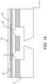
FIG. 14 is a cross-sectional view, not to scale of a fluid ejector chip containing an adhesive sealing tape according to a ninth embodiment of the disclosure. -
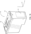
FIG. 15 , is a top perspective view of fluid fillable cartridge having a cover containing air vents therein. - For the purposes of this disclosure, the term "label" may be used interchangeably with the term "tape." The label is typically a polymeric, elastomeric, or fibrous-based backing material containing an adhesive layer for joining the label or adhesive sealing tape to a fluid ejection cartridge. A suitable backing material for the adhesive layer may be selected from thin film plastics such as a polyethylene terephthalate (PET), polyvinyl chloride (PVC), polyamide (PA), or synthetic paper such as YUPO FPG 80. The thickness of the backing material may range from about 20 to about 200 microns, preferably about 50 to about 70 microns.
- Suitable adhesives used for adhesive sealing tapes, as described herein, may have an initial removal force of about 9 gram-force per centimeter of sealing tape width that increase to about 45 gram-force per centimeter of sealing tape width after two years. A particularly suitable adhesive material is either a silicone or acrylic adhesive. The thickness of adhesive applied to the backing material may range from about 5 to about 25 microns. A cross-sectional view of an
adhesive sealing tape 2 containing abacking material 4 and anadhesive layer pattern 6 attached to afluid ejector chip 8 having an array of nozzle holes 10 therein is illustrated inFIG. 1 . - A
fluid fillable cartridge 12 is illustrated inFIGs. 2 and3 . A fluid fillable cartridge is defined as a fluid cartridge containing one or more open-top fluid reservoirs. In this case, thefluid fillable cartridge 12 includes two open-top fluid reservoirs fluid fillable cartridge 12 includes one dividingwall 16 between the twofluid reservoirs body 18 of the fluid fillable cartridge is typically a unitary molded body made of a polymeric material that is compatible with fluids inserted into the open-top fluid reservoirs - A
fluid ejector chip 20 containingarrays external surface 24 of the fluid fillable cartridge body by means of aflexible circuit 26. Referring again toFIG. 3 ,fluid supply slots top fluid reservoirs fluid ejector chip 20. - In order to protect the nozzle holes from contamination and debris during shipping and handling of the
fluid fillable cartridge 12, a protective adhesive sealing tape is attached to thefluid fillable cartridge 12. A first embodiment of theadhesive sealing tape 2 is illustrated inFIGs. 1 and4 . In this embodiment, theadhesive sealing tape 2 contains anadhesive layer pattern 6 that surrounds anarray 10 of nozzle holes and fluid ejectors on thefluid ejector chip 8, but theadhesive sealing tape 2 is devoid of adhesive in thearea 30 adjacent to thearray 10 of nozzle holes. The adhesive of theadhesive sealing tape 2 is patterned in such a way that the adhesive does not overlap any of thearray 10 of nozzle holes of thefluid ejector chip 8. Theadhesive layer pattern 6 may be provided as a frame around thearray 10 of nozzle holes as shown inFIG. 1 , or the entireadhesive sealing tape 40 may have an adhesive layer pattern as shown inFIG. 5 provided there is no adhesive in thearea 42 adjacent to thearray 10 of nozzle holes. - In another embodiment, illustrated in
FIG. 6 , thefluid ejector chip 20 contains multiple arrays of nozzle holes and fluid ejectors therefor, such asarrays adhesive sealing tape 46 contains anadhesive backing 48 that is patterned to isolate thearrays adhesive strip 44 betweeen thearrays top reservoirs - Another embodiment is illustrated in
FIG.7 . In this embodiment, theadhesive sealing tape 50 is cut to a size and shape so that the adhesive sealing tape covers a portion of theexternal surface 52 of the cartridge body beyond the area of thefluid ejector chip 8. Theadhesive pattern 54 may be applied in such a way as to seal around the perimeter of thefluid ejector chip 8. This embodiment of theadhesive sealing tape 50 may be useful in cases where it is not necessary to fill the fluid fillable cartridge prior to reaching the end user, but it is still necessary to protect thefluid ejector chip 8 from contamination and debris. This embodiment may also allow a wider tolerance for placement of theadhesive sealing tape 50 on the cartridge body compared to the embodiments ofFIGs. 4-6 thereby reducing assembly costs for the fluid fillable cartridge. -
FIG. 8 is a bottom side view of a fluidfillable cartridge 56 containing anadhesive sealing tape 58 with anadhesive pattern 60 that surrounds afluid ejector chip 62 as described with reference toFIG. 7 wherein an area of theadhesive sealing tape 58 covering thefluid ejector chip 62 is devoid of adhesive. Theadhesive sealing tape 58 may also be provided with apull tab 64 that is also devoid of adhesive and may be used by a user to remove theadhesive sealing tape 58 from thefluid fillable cartridge 56. Accordingly, all of the adhesive sealing tapes described in the preceding embodiments may include an extra length of backing material that extends beyond the fluid ejector chip and has a non-adhesive area to use as thepull tab 64 to assist in removing the adhesive sealing tape from the cartridge. The length by which the backing material extends may be immediately beyond the adhesive or further so that thepull tab 64 may wrap around or extend past a side of the cartridge body to a more readily visible and convenient to the user. - While the foregoing embodiments illustrate an adhesive sealing tape specifically configured to protect the fluid ejector chip from contamination and debris, the adhesive sealing tape may also be extended to cover other portions of the fluid fillable cartridge.
FIG. 9 is a top perspective view of thefluid fillable cartridge 56, wherein anadhesive sealing tape 66 is extended to cover an open-top fluid reservoir 68 in thecartridge 56 to seal the open-top fluid reservoir 68 thereby preventing debris from collecting in thereservoir 68 during handling and shipping. Theadhesive sealing tape 66 may include adhesive to attach the adhesive sealing tape to anedge 69 around the perimeter of the open topfluid reservoir 68 or adhesive may be applied to the entire area covering the open-top fluid reservoir 68. As described above, apull tab 64 may also be included to assist in removing theadhesive sealing tape 66 from thecartridge 56.FIG. 9 illustrates theadhesive sealing tape 66 only attached to one side of thefluid fillable cartridge 56. However, as shown inFIG. 10 , the adhesive sealing tape may have anextension 72 containing adhesive that attaches to a second side of thefluid fillable cartridge 56. - In another embodiment illustrated in
FIGs. 11-13 , anadhesive sealing tape 74 having apull tab 76 is cut so that the adhesive sealing tape is wrapped around afront side 78 of the fluid fillable cartridge without interfering with electrical connections on theflexible circuit 24 so that the electrical connections may be used to test the fluid ejector chip attached to thefluid fillable cartridge 56.FIG. 12 is an exploded top perspective view of thefluid fillable cartridge 56 and adhesive sealingtape 74 showing the pattern of adhesive 80 that surrounds the fluidejector chip area 82 that is devoid of adhesive.FIG. 13 is an exploded bottom perspective view of thefluid fillable cartridge 56 and adhesive sealingtape 74 showing the pattern of adhesive 84 that covers the open-top fluid reservoir 68. - In some embodiments, as illustrated in
FIG. 14 , anentire backing material 90 used for theadhesive sealing tape 92 is covered with adhesive 94. In areas of the adhesive sealing tape that would be in contact with the nozzle holes 10 of thefluid ejector chip 8, abuffer material 96 may be applied to a portion of theadhesive sealing tape 92 adjacent to the nozzle holes 10. Thebuffer material 96 is non-adhesive and may prevent any residue from contacting the nozzle holes. - In some embodiments, an adhesive preform is applied to the fluid fillable cartridge so that the adhesive preform surrounds the nozzle holes in the fluid ejector chip without overlapping the nozzle holes. A backing material is then applied to the adhesive preform to act as a seal to prevent debris and contamination from contacting the nozzle holes and to act as a seal for the fluid ejector chip. The adhesive preform is cut in such a way that when applied to the fluid ejector chip that the adhesive preform forms a window around the nozzle holes similar to the adhesive pattern of
FIGs, 1 and3-4 , with no adhesive contacting the nozzle holes. The backing material applied to the adhesive preform is devoid of adhesive. - In some embodiments, as illustrated for example in
FIG. 15 , a fluidfillable cartridge 100 includes acover 102 attached to thecartridge body 104. Thecover 102 includesair vents 106 for preventing a backpressure in the fluid fillable cartridge during fluid ejection. When the fluidfillable cartridge 100 contains acover 102 with air vents therein, an adhesive sealing tape may also be extended over thecover 102 to cover and protect theair vents 106 from debris during shipping and handling of the fluidfillable cartridge 100. - For the purposes of this specification and appended claims, unless otherwise indicated, all numbers expressing quantities, percentages or proportions, and other numerical values used in the specification and claims, are to be understood as being modified in all instances by the term "about." Accordingly, unless indicated to the contrary, the numerical parameters set forth in the following specification and attached claims are approximations that can vary depending upon the desired properties sought to be obtained by the present disclosure. At the very least, and not as an attempt to limit the application of the doctrine of equivalents to the scope of the claims, each numerical parameter should at least be construed in light of the number of reported significant digits and by applying ordinary rounding techniques.
- While particular embodiments have been described, alternatives, modifications, variations, improvements, and substantial equivalents that are or can be presently unforeseen can arise to applicants or others skilled in the art. Accordingly, the appended claims as filed and as they can be amended are intended to embrace all such alternatives, modifications, variations, improvements, and substantial equivalents.
Claims (16)
- A fluid fillable cartridge (12, 56, 100), characterized in that comprising:an open fluid reservoir (14a, 14b, 68) therein; anda fluid ejector chip (8, 20, 62), attached to an exposed surface of the fluid fillable cartridge (12, 56, 100) opposite to the open fluid reservoir (14a, 14b, 68),wherein the fluid fillable cartridge (12, 56, 100) comprising an adhesive sealing tape (2, 40, 46, 50, 58, 66, 74, 92) attached to the fluid fillable cartridge (12, 56, 100),wherein the adhesive sealing tape (2, 40, 46, 50, 58, 66, 74, 92) comprises an adhesive pattern (6, 54, 60, 94) on a first end of the adhesive sealing tape (2, 40, 46, 50, 58, 66, 74, 92) that is configured to attach the adhesive sealing tape (2, 40, 46, 50, 58, 66, 74, 92) adjacent to the fluid ejector chip (8, 20, 62) while being devoid of adhesive in nozzle hole areas (10, 22a, 22b) of the fluid ejector chip (8, 20, 62).
- The fluid fillable cartridge (56) of claim 1, wherein
the adhesive sealing tape (66, 74) further comprises an adhesive pattern on a second end of the adhesive sealing tape (66, 74) distal from the first end of the adhesive sealing tape (66, 74) that is configured to seal the open fluid reservoir (68) in the fluid fillable cartridge (56). - The fluid fillable cartridge (56) of claim 2, wherein
the adhesive sealing tape (66, 74) is configured to wrap around a first side wall of the fluid fillable cartridge (56) from the first end of the adhesive sealing tape (66, 74) to the second end of the adhesive sealing tape (66, 74). - The fluid fillable cartridge (56) of claim 3, wherein
the first end of the adhesive sealing tape (66, 74) is configured to overlap a second side wall of the fluid fillable cartridge (56). - The fluid fillable cartridge (12) of claim 1, wherein
the adhesive pattern (6) on the first end of a backing material (4) of the adhesive sealing tape (2) is configured to attach the adhesive sealing tape (2) to a body area (18) of the fluid fillable cartridge (12) adjacent to the fluid ejector chip (8). - The fluid fillable cartridge (12) of claim 5, wherein
the adhesive pattern (6) on the first end of the backing material (4) is configured to avoid adhesive contact with the fluid ejector chip (8). - A method for preventing contamination of nozzle holes (10, 22a, 22b) in a fluid ejector chip (8, 20, 62), characterized in that comprising:providing a fluid fillable cartridge (12, 56, 100) having an open fluid reservoir (14a, 14b, 68) therein and the fluid ejector chip (8, 20, 62) attached to an exposed surface of the fluid fillable cartridge (12, 56, 100) opposite to the open fluid reservoir (14a, 14b, 68), andattaching an adhesive sealing tape (2, 40, 46, 50, 58, 66, 74, 92) to the fluid fillable cartridge (12, 56, 100), wherein the adhesive sealing tape (2, 40, 46, 50, 58, 66, 74, 92) is patterned with an adhesive (6) on a first end of a backing material (4, 90) of the adhesive sealing tape (2, 40, 46, 50, 58, 66, 74, 92) that is configured to attach the adhesive sealing tape (2, 40, 46, 50, 58, 66, 74, 92) adjacent to the fluid ejector chip (8, 20, 62) while being devoid of adhesive in nozzle hole areas (10, 22a, 22b) of the fluid ejector chip (8, 20, 62).
- The method of claim 7, wherein
the adhesive sealing tape (66, 74) comprises an adhesive pattern on a second end of the adhesive sealing tape (66, 74) distal from the first end of the adhesive sealing tape (66, 74) that is configured to seal the open fluid reservoir (68) in the fluid fillable cartridge (56). - The method of claim 8, further comprising:
wrapping the adhesive sealing tape (66, 74) around a first side wall of the fluid fillable cartridge (56) from the first end of the adhesive sealing tape (66, 74) to the second end of the adhesive sealing tape (66, 74). - The method of claim 9, wherein
the first end of the adhesive sealing tape (66, 74) is configured to overlap a second side wall of the fluid fillable cartridge (56). - The method of claim 7, wherein
the adhesive sealing tape (2) is patterned with the adhesive (6) on the first end of the backing material (4) to attach the adhesive sealing tape (2) to a body area (18) of the fluid fillable cartridge (12) adjacent to the fluid ejector chip (8) without adhesive overlapping the fluid ejector chip (8). - A method for making an adhesive sealing tape (2, 40, 46, 50, 58, 66, 74, 92) for a fluid fillable cartridge (12, 56, 100), characterized in that the method comprising:providing a backing material (4) for the adhesive sealing tape (2, 40, 46, 50, 58, 66, 74, 92), wherein the backing material (4) has a first end and a second end distal from the first end, andapplying an adhesive (6) to the first end of the backing material (4), wherein the adhesive sealing tape (2, 40, 46, 50, 58, 66, 74, 92) has an adhesive pattern (6, 54, 60, 94) that is configured to attach the adhesive sealing tape (2, 40, 46, 50, 58, 66, 74, 92) adjacent to a fluid ejector chip (8, 20, 62) of the fluid fillable cartridge (12, 56, 100) while being devoid of adhesive in nozzle hole areas (10, 22a, 22b) of the fluid ejector chip (8, 20, 62).
- The method of claim 12, further comprising:
applying an adhesive pattern to the second end of the backing material (4) distal from the first end of the backing material (4) that is configured to seal an open fluid reservoir (68) in the fluid fillable cartridge (56). - The method of claim 13, further comprising:
wrapping the adhesive sealing tape (66, 74) around a first side wall of the fluid fillable cartridge (56) from the first end of the backing material (4) to the second end of the backing material (4). - The method of claim 14, wherein
The first end of the adhesive sealing tape (66, 74) is configured to overlap a second side wall of the fluid fillable cartridge (56). - The method of claim 12, whereinthe backing material (4) is patterned with the adhesive (6) on the first end of the backing material (4),wherein the adhesive pattern (6, 54, 60, 94) is sufficient to attach the adhesive sealing tape (2) to a body area (18) of the fluid fillable cartridge (12) adjacent to the fluid ejector chip (8) without adhesive overlapping the fluid ejector chip (8).
Applications Claiming Priority (1)
| Application Number | Priority Date | Filing Date | Title |
|---|---|---|---|
| US17/818,961 US12023935B2 (en) | 2022-08-10 | 2022-08-10 | Nozzle sealing tape |
Publications (1)
| Publication Number | Publication Date |
|---|---|
| EP4321342A1 true EP4321342A1 (en) | 2024-02-14 |
Family
ID=87378081
Family Applications (1)
| Application Number | Title | Priority Date | Filing Date |
|---|---|---|---|
| EP23185797.0A Withdrawn EP4321342A1 (en) | 2022-08-10 | 2023-07-17 | Fluid fillable cartridge, method for preventing contamination, method for making adhesive sealing tape |
Country Status (4)
| Country | Link |
|---|---|
| US (2) | US12023935B2 (en) |
| EP (1) | EP4321342A1 (en) |
| JP (1) | JP2024025704A (en) |
| CN (1) | CN117584632B (en) |
Cited By (1)
| Publication number | Priority date | Publication date | Assignee | Title |
|---|---|---|---|---|
| US12350941B2 (en) | 2022-08-10 | 2025-07-08 | Brady Worldwide, Inc. | Nozzle sealing tape |
Citations (4)
| Publication number | Priority date | Publication date | Assignee | Title |
|---|---|---|---|---|
| US5262802A (en) * | 1989-09-18 | 1993-11-16 | Canon Kabushiki Kaisha | Recording head assembly with single sealing member for ejection outlets and for an air vent |
| US6588875B1 (en) * | 2001-12-04 | 2003-07-08 | John W. Kleinhammer | Ink jet cartridge printhead seal |
| US20060221119A1 (en) * | 2005-03-31 | 2006-10-05 | Lexmark International, Inc. | Orifice plate protection device |
| US20220226806A1 (en) * | 2021-01-20 | 2022-07-21 | Funai Electric Co., Ltd. | Pipette-Fillable Printhead Body |
Family Cites Families (54)
| Publication number | Priority date | Publication date | Assignee | Title |
|---|---|---|---|---|
| JPS5865668A (en) | 1981-10-14 | 1983-04-19 | Konishiroku Photo Ind Co Ltd | Storage of ink jet print head |
| JP3151903B2 (en) | 1992-01-28 | 2001-04-03 | セイコーエプソン株式会社 | Ink jet recording head and recording device |
| JP3127573B2 (en) | 1992-06-04 | 2001-01-29 | セイコーエプソン株式会社 | Ink jet recording head and method of manufacturing the same |
| JPH05338160A (en) | 1992-06-05 | 1993-12-21 | Seiko Epson Corp | Ink jet recording head |
| JPH0664179A (en) | 1992-08-20 | 1994-03-08 | Canon Inc | Inkjet recording head |
| US5414454A (en) | 1993-04-30 | 1995-05-09 | Hewlett-Packard Company | Slit nozzle tape for inkjet printhead |
| DE4326564C2 (en) | 1993-08-07 | 1998-05-28 | Eastman Kodak Co | Nozzle cover for an ink printhead and method for applying the same |
| JPH07137277A (en) | 1993-11-15 | 1995-05-30 | Canon Inc | Ink container packaging material |
| JPH08230205A (en) | 1995-02-28 | 1996-09-10 | Canon Inc | Ink tank protection method and member, and ink tank having the same |
| JPH0958009A (en) | 1995-08-23 | 1997-03-04 | Seiko Epson Corp | Ink cartridge, its packaging case, and packaging method |
| US5847735A (en) | 1996-04-26 | 1998-12-08 | Pelikan Produktions Ag | Ink cartridge for a printer |
| JP3671555B2 (en) | 1996-10-30 | 2005-07-13 | 富士ゼロックス株式会社 | Ink tank |
| JPH11320897A (en) | 1998-03-11 | 1999-11-24 | Canon Inc | Recording head cap, recording head to which the cap can be attached, method and apparatus for attaching cap to recording head |
| DE60003767T2 (en) | 1999-10-29 | 2004-06-03 | Hewlett-Packard Co. (N.D.Ges.D.Staates Delaware), Palo Alto | Inkjet printhead with improved reliability |
| JP2001150668A (en) | 1999-11-25 | 2001-06-05 | Seiko Instruments Inc | Inkjet head |
| KR100385970B1 (en) | 1999-12-23 | 2003-06-02 | 삼성전자주식회사 | A sealing apparatus of inkjet print head |
| US6764170B2 (en) | 2001-06-14 | 2004-07-20 | Hewlett-Packard Development Company, L.P. | Removable label for sealing an ink-jet ink reservoir |
| CN1149150C (en) * | 2001-08-23 | 2004-05-12 | 国际联合科技股份有限公司 | Adhesive tape set for sealing jet orifice of ink-jet printing head |
| US6634732B2 (en) * | 2001-09-11 | 2003-10-21 | Hewlett-Packard Development Company, L.P. | Thermoplastic polymer film sealing of nozzles on fluid ejection devices and method |
| JP3885872B2 (en) | 2001-10-09 | 2007-02-28 | ブラザー工業株式会社 | Ink storage device and ink jet recording apparatus including the same |
| JP2003118140A (en) | 2001-10-16 | 2003-04-23 | Seiko Epson Corp | Reduced pressure packaged ink cartridge and reduced pressure packaging method |
| US6722756B2 (en) | 2002-07-01 | 2004-04-20 | Hewlett-Packard Development Company, L.P. | Capping shroud for fluid ejection device |
| US6764165B2 (en) | 2002-09-30 | 2004-07-20 | Hewlett-Packard Development Company, L.P. | Fluid ejection device and method of manufacturing a fluid ejection device |
| US20050029158A1 (en) | 2003-07-30 | 2005-02-10 | Hewlett-Packard Development Company, L.P. | Packaging assembly and method |
| JP2005111974A (en) | 2003-09-19 | 2005-04-28 | Fuji Xerox Co Ltd | Inkjet recording head and inkjet recording device |
| US7025439B2 (en) | 2004-03-15 | 2006-04-11 | Lexmark International, Inc. | Ink jet printer with extended nozzle plate and method |
| KR100656513B1 (en) | 2004-07-12 | 2006-12-13 | 삼성전자주식회사 | Inkjet Cartridge Nozzle Tape |
| JP2006137104A (en) | 2004-11-12 | 2006-06-01 | Canon Inc | Protective tape for liquid discharge head |
| JP2006159513A (en) | 2004-12-03 | 2006-06-22 | Canon Inc | Liquid discharge head and protective tape for the head |
| JP2006198937A (en) | 2005-01-21 | 2006-08-03 | Canon Inc | Ink jet recording head and manufacturing method thereof |
| JP2006212796A (en) * | 2005-02-01 | 2006-08-17 | Canon Inc | Protective member for ink jet recording head and method for storing ink jet recording head using this protective member |
| JP2007160864A (en) | 2005-12-16 | 2007-06-28 | Canon Inc | Liquid discharge head |
| JP4926537B2 (en) | 2006-05-09 | 2012-05-09 | キヤノン株式会社 | LIQUID DISCHARGE HEAD, INKJET CARTRIDGE, LIQUID DISCHARGE HEAD PROTECTIVE ADHESION METHOD AND LIQUID DISCHARGE HEAD PROTECTIVE TAPE |
| JP5020624B2 (en) | 2006-12-22 | 2012-09-05 | キヤノン株式会社 | Head cartridge, protective tape, and ejection port sealing method for ink jet recording head cartridge |
| JP4380713B2 (en) | 2007-03-01 | 2009-12-09 | セイコーエプソン株式会社 | Manufacturing method of liquid jet head unit |
| US7984967B2 (en) | 2007-04-13 | 2011-07-26 | Canon Kabushiki Kaisha | Ink jet head |
| US8083321B2 (en) * | 2007-05-23 | 2011-12-27 | Lexmark International, Inc. | Removable radiation cured composition and process for protecting a micro-fluid ejection head |
| JP4664944B2 (en) | 2007-06-18 | 2011-04-06 | 株式会社リコー | Refill ink cartridge |
| US8087747B2 (en) | 2007-07-10 | 2012-01-03 | Canon Kabushiki Kaisha | Ink jet recording head unit and production process thereof |
| JP4902477B2 (en) | 2007-09-26 | 2012-03-21 | シャープ株式会社 | Inkjet head unit |
| US8496320B2 (en) | 2008-05-08 | 2013-07-30 | Hewlett-Packard Development Company, L.P. | Ink cartridge having a staked vent sealing member |
| CN102015313B (en) | 2008-05-08 | 2015-03-25 | 惠普开发有限公司 | Ink cartridge with thermally fused vent sealing member |
| JP5178345B2 (en) | 2008-06-25 | 2013-04-10 | キヤノン株式会社 | Liquid discharge head unit |
| JP5532227B2 (en) | 2010-03-25 | 2014-06-25 | セイコーエプソン株式会社 | Liquid ejecting head and liquid ejecting apparatus |
| JP6214286B2 (en) | 2013-09-05 | 2017-10-18 | キヤノン株式会社 | Tape unit, liquid discharge head, and recording apparatus |
| JP5811378B2 (en) | 2014-04-16 | 2015-11-11 | セイコーエプソン株式会社 | Liquid ejecting head, liquid ejecting apparatus, and method of manufacturing liquid ejecting head |
| US9132654B1 (en) | 2014-07-08 | 2015-09-15 | Funai Electric Co., Ltd. | Label for inkjet printhead |
| JP6734063B2 (en) | 2016-01-29 | 2020-08-05 | 理想科学工業株式会社 | ink cartridge |
| US10814638B2 (en) * | 2018-05-08 | 2020-10-27 | Funai Electric Co. Ltd | Fluidic ejection cartridge for improved protective tape removal |
| US10987935B1 (en) * | 2020-01-14 | 2021-04-27 | Funai Electric Co. Ltd | Organic solvent sealing tape |
| JP7527869B2 (en) | 2020-07-07 | 2024-08-05 | キヤノン株式会社 | Storage device and liquid ejection device |
| WO2023149893A1 (en) | 2022-02-04 | 2023-08-10 | Hewlett-Packard Development Company, L.P. | Fluid ejection device components |
| US12023935B2 (en) | 2022-08-10 | 2024-07-02 | Funai Electric Co., Ltd. | Nozzle sealing tape |
| JP2024149426A (en) | 2023-04-07 | 2024-10-18 | キヤノン株式会社 | LIQUID CARTRIDGE AND METHOD FOR HANDLING PROTECTIVE MEMBER FOR LIQUID CARTRIDGE |
-
2022
- 2022-08-10 US US17/818,961 patent/US12023935B2/en active Active
-
2023
- 2023-07-17 EP EP23185797.0A patent/EP4321342A1/en not_active Withdrawn
- 2023-07-17 CN CN202310872822.8A patent/CN117584632B/en active Active
- 2023-08-03 JP JP2023127194A patent/JP2024025704A/en active Pending
-
2024
- 2024-05-30 US US18/677,967 patent/US12350941B2/en active Active
Patent Citations (4)
| Publication number | Priority date | Publication date | Assignee | Title |
|---|---|---|---|---|
| US5262802A (en) * | 1989-09-18 | 1993-11-16 | Canon Kabushiki Kaisha | Recording head assembly with single sealing member for ejection outlets and for an air vent |
| US6588875B1 (en) * | 2001-12-04 | 2003-07-08 | John W. Kleinhammer | Ink jet cartridge printhead seal |
| US20060221119A1 (en) * | 2005-03-31 | 2006-10-05 | Lexmark International, Inc. | Orifice plate protection device |
| US20220226806A1 (en) * | 2021-01-20 | 2022-07-21 | Funai Electric Co., Ltd. | Pipette-Fillable Printhead Body |
Cited By (1)
| Publication number | Priority date | Publication date | Assignee | Title |
|---|---|---|---|---|
| US12350941B2 (en) | 2022-08-10 | 2025-07-08 | Brady Worldwide, Inc. | Nozzle sealing tape |
Also Published As
| Publication number | Publication date |
|---|---|
| JP2024025704A (en) | 2024-02-26 |
| CN117584632B (en) | 2026-04-28 |
| US20240051305A1 (en) | 2024-02-15 |
| US12350941B2 (en) | 2025-07-08 |
| US20240316941A1 (en) | 2024-09-26 |
| US12023935B2 (en) | 2024-07-02 |
| CN117584632A (en) | 2024-02-23 |
Similar Documents
| Publication | Publication Date | Title |
|---|---|---|
| US6206499B1 (en) | Ink-jet recording head | |
| EP0729835B1 (en) | Member and method for protecting ink tank | |
| US12350941B2 (en) | Nozzle sealing tape | |
| US6793332B2 (en) | Ink housing device effectively preventing ink leakage | |
| US7984967B2 (en) | Ink jet head | |
| JP4380713B2 (en) | Manufacturing method of liquid jet head unit | |
| JP5532227B2 (en) | Liquid ejecting head and liquid ejecting apparatus | |
| CN113426615B (en) | Fluid ejection cartridge and method of removing protective tape from an ejection head thereof | |
| US9132654B1 (en) | Label for inkjet printhead | |
| EP0638426A1 (en) | Nozzle cover for an inkjet print head and method for applying the same | |
| JP5811378B2 (en) | Liquid ejecting head, liquid ejecting apparatus, and method of manufacturing liquid ejecting head | |
| US12059903B2 (en) | Storage device and liquid ejection apparatus | |
| EP1103381A2 (en) | Ink jet head | |
| JPH05338160A (en) | Ink jet recording head | |
| JPS5865668A (en) | Storage of ink jet print head | |
| JP3671555B2 (en) | Ink tank | |
| JPH07137277A (en) | Ink container packaging material | |
| JP6214286B2 (en) | Tape unit, liquid discharge head, and recording apparatus | |
| JP2006159513A (en) | Liquid discharge head and protective tape for the head | |
| JP2007160864A (en) | Liquid discharge head | |
| CN118650988A (en) | Liquid ejecting head and liquid ejecting device | |
| JP2005111974A (en) | Inkjet recording head and inkjet recording device | |
| JPH0664179A (en) | Inkjet recording head | |
| KR20010057861A (en) | A sealing apparatus of inkjet print head | |
| JP2006137104A (en) | Protective tape for liquid discharge head |
Legal Events
| Date | Code | Title | Description |
|---|---|---|---|
| PUAI | Public reference made under article 153(3) epc to a published international application that has entered the european phase |
Free format text: ORIGINAL CODE: 0009012 |
|
| STAA | Information on the status of an ep patent application or granted ep patent |
Free format text: STATUS: THE APPLICATION HAS BEEN PUBLISHED |
|
| AK | Designated contracting states |
Kind code of ref document: A1 Designated state(s): AL AT BE BG CH CY CZ DE DK EE ES FI FR GB GR HR HU IE IS IT LI LT LU LV MC ME MK MT NL NO PL PT RO RS SE SI SK SM TR |
|
| STAA | Information on the status of an ep patent application or granted ep patent |
Free format text: STATUS: REQUEST FOR EXAMINATION WAS MADE |
|
| 17P | Request for examination filed |
Effective date: 20240325 |
|
| RBV | Designated contracting states (corrected) |
Designated state(s): AL AT BE BG CH CY CZ DE DK EE ES FI FR GB GR HR HU IE IS IT LI LT LU LV MC ME MK MT NL NO PL PT RO RS SE SI SK SM TR |
|
| STAA | Information on the status of an ep patent application or granted ep patent |
Free format text: STATUS: THE APPLICATION HAS BEEN WITHDRAWN |
|
| 18W | Application withdrawn |
Effective date: 20241126 |
|
| 19U | Interruption of proceedings before grant |
Effective date: 20241024 |