EP1103381A2 - Ink jet head - Google Patents
Ink jet head Download PDFInfo
- Publication number
- EP1103381A2 EP1103381A2 EP00310062A EP00310062A EP1103381A2 EP 1103381 A2 EP1103381 A2 EP 1103381A2 EP 00310062 A EP00310062 A EP 00310062A EP 00310062 A EP00310062 A EP 00310062A EP 1103381 A2 EP1103381 A2 EP 1103381A2
- Authority
- EP
- European Patent Office
- Prior art keywords
- nozzle plate
- plate
- cover
- channels
- nozzle
- Prior art date
- Legal status (The legal status is an assumption and is not a legal conclusion. Google has not performed a legal analysis and makes no representation as to the accuracy of the status listed.)
- Withdrawn
Links
Images


Classifications
-
- B—PERFORMING OPERATIONS; TRANSPORTING
- B41—PRINTING; LINING MACHINES; TYPEWRITERS; STAMPS
- B41J—TYPEWRITERS; SELECTIVE PRINTING MECHANISMS, i.e. MECHANISMS PRINTING OTHERWISE THAN FROM A FORME; CORRECTION OF TYPOGRAPHICAL ERRORS
- B41J2/00—Typewriters or selective printing mechanisms characterised by the printing or marking process for which they are designed
- B41J2/005—Typewriters or selective printing mechanisms characterised by the printing or marking process for which they are designed characterised by bringing liquid or particles selectively into contact with a printing material
- B41J2/01—Ink jet
- B41J2/135—Nozzles
- B41J2/14—Structure thereof only for on-demand ink jet heads
- B41J2/14201—Structure of print heads with piezoelectric elements
- B41J2/14209—Structure of print heads with piezoelectric elements of finger type, chamber walls consisting integrally of piezoelectric material
-
- B—PERFORMING OPERATIONS; TRANSPORTING
- B41—PRINTING; LINING MACHINES; TYPEWRITERS; STAMPS
- B41J—TYPEWRITERS; SELECTIVE PRINTING MECHANISMS, i.e. MECHANISMS PRINTING OTHERWISE THAN FROM A FORME; CORRECTION OF TYPOGRAPHICAL ERRORS
- B41J2/00—Typewriters or selective printing mechanisms characterised by the printing or marking process for which they are designed
- B41J2/005—Typewriters or selective printing mechanisms characterised by the printing or marking process for which they are designed characterised by bringing liquid or particles selectively into contact with a printing material
- B41J2/01—Ink jet
- B41J2/135—Nozzles
- B41J2/14—Structure thereof only for on-demand ink jet heads
- B41J2002/14362—Assembling elements of heads
Definitions
- the present invention relates to an ink jet head mounted on an ink jet recording apparatus applied to, for example, a printer or a facsimile machine.
- an ink jet recording apparatus for recording letters or images on a recording medium using a recording head for expelling ink from a plurality of nozzles is known.
- the recording head opposed to the recording medium is provided in a head holder, and the head holder is mounted on a carriage to scan the recording medium in a direction orthogonal to the direction of conveyance of the recording medium.
- Fig. 6 is an exploded perspective view showing the main part of an example of such a recording head.
- Figs. 7A and 7B are a side sectional view and a frontal sectional view taken along the line X-X in Fig. 7A, respectively, showing the main part of the recording head.
- a plurality of channels 102 are provided side by side in an actuator plate 101 formed of piezoelectric ceramic in its width direction.
- the channels 102 are separated from one another by side walls 103.
- One end portion of the channels 102 in the longitudinal direction extends to one end face of the actuator plate 101, while the other end portion does not extend to the other end face, with the depth being gradually decreased.
- An electrode 105 for applying drive voltage is formed on the surface of the opening side of both side walls 103 and 103 of each channel 102 over the longitudinal direction.
- a cover plate 107 is joined by an adhesive 109 to the opening side of the channels 102 in the actuator plate 101.
- the gap between the shallow portions of the rear end portion of the channels 102 in the actuator plate 101 and the cover plate 107 is sealed with sealant 110.
- the cover plate 107 has a common ink chamber 111 which is a concave portion communicating with the shallow, other end portion of the channels 102, and an ink supply port 112 piercing from the bottom portion of the common ink chamber 111 in the opposite direction from the channels 102.
- An ink flow path 114 of a flow path block 113 communicates with and opens to the ink supply port 112. Further, a filter 116 is attached to an end portion of the ink flow path 114 of the flow path block 113 on the side of the ink supply port 112.
- a nozzle plate 115 is affixed and joined by an adhesive to an end face where the channels 102 of the joined body of the actuator plate 101 and the cover plate 107 are open.
- the width of the nozzle plate 115 is larger than the width of the end face of the joined body and the length of the nozzle plate 115 is larger than the length of the end face of the joined body.
- Nozzle openings 117 are formed in the nozzle plate 115 at positions opposed to the channels 102, respectively. Further, as shown in Fig.
- a nozzle plate cover 118 is fixed by the adhesive to the rear surface of the nozzle plate 115 so as to cover the outer peripheral surface of an end portion of the joined body of the actuator plate 101 and the cover plate 107 and to cover the rear surface of the nozzle plate 115.
- a wiring board 120 is fixedly attached to a surface of the actuator plate 101 which is opposite to the side of the nozzle plate 115 and opposite to the side of the cover plate 107.
- Wirings 122 connectedto the electrodes 105, respectively, using bonding wires 121, a flexible substrate, or the like are formed on the wiring board 120, such that drive voltage can be applied to the electrodes 105 via the wirings 122.
- the channels 102 are filled with ink from the ink flow path 114 via the ink supply port 112 and the common ink chamber 111.
- predetermined drive voltage act on side walls 103 on both sides of a predetermined channel 102 via the electrodes 105 the side walls 103 are deformed to change the volume in the predetermined channel 102, which leads to expulsion of ink in the channel 102 from the nozzle opening 117.
- Fig. 8 which is a frontal sectional view showing the main part
- positive drive voltage is applied to electrodes 105a and 105b in the channel 102a while electrodes 105c and 105d opposed to the electrodes 105a and 105b, respectively, are grounded.
- drive electric field toward the channel 102a acts on the side walls 103a and 103b.
- a water-repellent film having water repellency is provided on the surface of the nozzle plate 115 which is opposed to a printed material for the purpose of preventing a head from getting dirty due to attachment of ink, preventing clogging of the nozzle openings 117, and the like. Further, the head end face is cleaned at predetermined regular time intervals or at a desired time. The cleaning is typically carried out by wiping out the face of the nozzle plate 115 which is opposed to a printed material with a wiper formed of, for example, rubber which has a relatively high hardness (Hs 40-50) and does not swell.
- Hs 40-50 relatively high hardness
- the whole thickness of the nozzle plate 115 is exposed. Therefore, there is a problem that, when the nozzle plate 115 is wiped out with a wiper, or, when a printed material (printed paper) is not properly fed and is jammed to be crumpled, force in the direction of peeling the nozzle plate 115 off the wiper or the printed material acts on the exposed nozzle plate 115, and thus, the nozzle plate 115 is peeled off the end face of the joined body of the actuator plate 101 and the cover plate 107.
- a printed material printed paper
- the present invention is made in view of these circumstances, and an object of the present invention is to provide an ink jet head in which a nozzle plate does not peel off the end face of a joined body of an actuator plate and a cover plate and the durability of which is expected to be improved.
- an ink jet head comprises: an actuator plate formed of piezoelectric ceramic with a plurality of channels formed therein, the channels opening to one surface and to one end face; a cover plate with a common ink chamber and an ink supply port formed therein, the common ink chamber being joined to the one surface of the actuator plate to seal a part of openings of the channels and to communicate with the channels, and the ink supply port piercing from the bottom portion of the common ink chamber in a direction opposite to the channels; a flow path block provided with a broad ink flow path, the inlet side thereof communicating with a narrow opening in proximity to an ink inflow port and the outlet side thereof communicating with the ink supply port; and a nozzle plate sealing the one end face of the actuator plate and having nozzle openings corresponding to the channels, respectively, the ink jet head expelling ink filled in the channels from the nozzle openings by applying drive voltage to electrodes provided on side walls of the channels and
- the whole thickness of the nozzle plate is not exposed. Therefore, when the nozzle plate is wiped out with a wiper, or, when a printed material (printed paper) is not properly fed and is jammed to be crumpled, force in the direction of peeling the nozzle plate off the wiper or the printed material does not greatly act on a greatly exposed edge, and thus, the peeling of the nozzle plate off the end face of the joined body of the actuator plate and the cover plate is prevented and the durability can be expected to be improved.
- a printed material printed paper
- an ink jet head of the above first aspect of the invention is characterized in that the nozzle plate is formed so as to protrude from the outer edge of a front end of the joined body of the actuator plate and the cover plate, and the nozzle plate cover is shaped so as to surround the outer periphery and the rear surface of the nozzle plate.
- an ink jet head of the above first or second aspect of the invention is characterized in that the surface of the nozzle plate which is opposed to a printed material protrudes from the surface of the nozzle plate cover which is opposed to a printed material by 0 ⁇ m or more and half of the thickness of the nozzle plate or less.
- the peripheral surface of the nozzle plate is exposed more greatly than the nozzle plate cover for protection.
- force in the direction of peeling the nozzle plate off the wiper or the printed material acts on the exposed edges and the side surface of the nozzle plate, and thus, the nozzle plate is liable to peel off the end face of the joined body of the actuator plate and the cover plate.
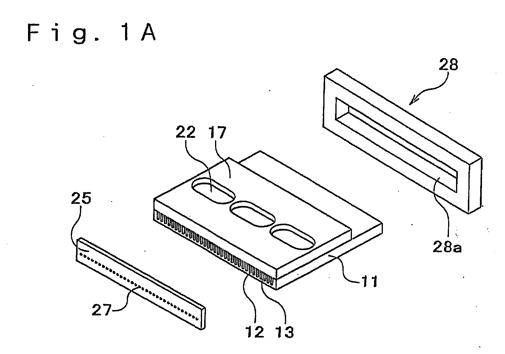
- Fig. 1A, 1B are exploded perspective views of an embodiment of an ink jet head according to the present invention.
- Fig. 1A is an overall view
- Fig. 1B is a partially broken exploded perspective view
- Fig. 2 is a perspective view of the embodiment when assembled
- Fig. 3 is a longitudinal sectional.
- a plurality of channels 12 are provided side by side in an actuator plate 11 formed of piezoelectric ceramic in its width direction.
- the channels 12 are separated from one another by side walls 13.
- One end portion of the channels 12 in the longitudinal direction is provided to extend to an end face of the actuator plate 11, while the other end portion is formed so as not to extend to the other end face, with the depth being gradually decreased.
- An electrode 15 for applying drive voltage is formed on the surface of the opening side of both side walls 13 and 13 of each channel 12 over the longitudinal direction.
- a cover plate 17 is joined by an adhesive to the opening side of the channels 12 in the actuator plate 11.
- the cover plate 17 has a common ink chamber 21 which is a concave portion communicating with the shallow, other end portion of the channels 12, and an ink supply port 22 piercing from the bottom portion of the common ink chamber 21 in the opposite direction from the channels 12.
- An ink flow path 24 of a flow path block 23 communicates with and opens to the ink supply port 22.
- a flow path block 23 has a built-in ink inflow port 29 for receiving ink conveyed from an ink cartridge which is not shown in the figures via a tube which is not shown in the figures, and has a built-in broad ink flow path 24 communicating with a narrow opening 26 on the outlet side of the ink inflow port 29, with the outlet side of the ink flow path 24 communicating with the ink supply port 22. Further, a filter 20 for removing a foreign matter in the ink is attached to an end portion of the ink flow path 24 of the flow path block 23 on the side of the ink supply port 22.
- the cover plate 17 can be formed of a ceramic plate, a metal plate, or the like, taking into consideration of deformation after joining to the actuator plate 11 formed of piezoelectric ceramic, it is preferable to use a ceramic plate having similar thermal expansion, particularly a piezoelectric ceramic plate.
- a nozzle plate 25 is affixed and joined by an adhesive to an end face where the channels 12 of the joined body of the actuator plate 11 and the cover plate 17 are open.
- Nozzle openings 27 are formed in the nozzle plate 25 at positions corresponding to the channels 12, respectively.
- the nozzle plate 25 is formed to be a little larger than the area of the end face where the channels 12 of the joined body of the actuator plate 11 and the cover plate 17 are open.
- the nozzle plate 25 is a polyimide film or the like with the nozzle openings 27 formed therein having the diameter of, for example, 25 ⁇ m using, for example, an excimer laser system.
- a water-repellent film having water repellency is provided on the surface of the nozzle plate 25 which is opposed to a printed material for the purpose of preventing attachment of ink and the like.
- a nozzle plate cover 28 having an opening 28a which can be fit to the nozzle plate 25 is disposed on an outer side surface of the nozzle plate 25 and on the periphery of the end portion where the channels 12 of the joined body of the actuator plate 11 and the cover plate 17 are open, and is joined by the adhesive to a part of the rear surface and the side surface of the nozzle plate 25 and to the outer side surface of the joined body of the actuator plate 11 and the cover plate 17.
- the nozzle plate cover 28 is for protecting the nozzle plate 25 from the situation that, when the nozzle plate 25 is wiped out with a wiper, or, when a printed material (printed paper) is not properly fed and is jammed to be crumpled, force in the direction of peeling the nozzle plate 25 off the wiper or the printed material acts and the nozzle plate 25 is peeled off the end face of the joined body of the actuator plate 11 and the cover plate 17.
- the nozzle plate cover 28 is attached such that the surface of the nozzle plate 25 which is opposed to a printed material is flush with the surface of the nozzle plate cover 28 which is opposed to a printed material or protrudes from the surface of the nozzle plate cover by a predetermined amount L.
- the protrusion amount L of the nozzle plate 25 in relation to the nozzle plate cover 28 is preferably 0 ⁇ m or larger and is half of the thickness of the nozzle plate or smaller.
- the protrusion amount L is preferably 25 ⁇ m or smaller. If the protrusion amount L is a negative value less than 0 ⁇ m, the wiping of the nozzle plate 25 with the wiper is not carried out satisfactorily, which is not preferable. Further, when L is larger than half of the thickness of the nozzle plate, the side surface of the nozzle plate 25 is exposed more greatly than the nozzle plate cover 28 for protection.
- nozzle plate 25 When the nozzle plate 25 is wiped out with a wiper, or, when a printed material (printed paper) is not properly fed and is jammed to be crumpled, force in the direction of peeling the nozzle plate off the wiper or the printed material acts on the exposed edge and the side surface, and thus, the nozzle plate 25 is liable to peel off the end face of the joined body of the actuator plate 11 and the cover plate 17, which is not preferable.
- a printed material printed paper
- the nozzle plate cover 28 and the nozzle plate 25 are positioned with a relatively high accuracy in this way, it is preferable that the nozzle plate cover 28 is formed of a material having a high rigidity, for example, stainless steel, aluminum, hard plastic, or the like.
- nozzle plate cover 28 is preferably integrally formed as shown in the figures, it may be structured to be dividable into two, for example.
- the end portion of the nozzle plate 25 on the side opposite to the surface opposed to a printed material is surrounded by the nozzle plate cover 28. Therefore, a situation is prevented in which, when the nozzle plate 25 is wiped out with a wiper, or, when a printed material (printed paper) is not properly fed and is jammed to be crumpled, force in the direction of peeling the nozzle plate 25 off the wiper or the printed material acts and the nozzle plate 25 is peeled off the end face of the joined body of the actuator plate 11 and the cover plate 17. This improves the durability.
- An ink jet head 30 (see Fig. 2) structured in this way is formed by, first, joining the actuator plate 11 formed of piezoelectric ceramic and the cover plate 17 using the adhesive, then joining the nozzle plate 25 to the end face of the joined body using the adhesive, and, at the same time, fitting and adhering the nozzle plate cover 28 onto the outer side surface of the nozzle plate 25 and onto the-joined body of the actuator plate 11 and the cover plate 17.
- Fig. 4 is a longitudinal sectional side showing another embodiment of an ink jet head according to the present invention.
- the nozzle plate 25 is formed such that its width is larger than the width of the end face of the joined body of the actuator plate 11 and the cover plate 17. Also, although not shown in the figures, the nozzle plate 25 is formed such that its length is larger than the length of the end face of the joined body of the actuator plate 11 and the cover plate 17.
- the nozzle plate cover 28 is formed so as to surround the peripheral surface of the nozzle plate 25 and so as to surround the outer periphery and the rear surface of the nozzle plate. The base portion of the nozzle plate cover 28 is joined to the outer peripheral surface of the end portion of the joined body of the actuator plate 11 and the cover plate 17.
- the protrusion amount L of the nozzle plate 25 in relation to the nozzle plate cover 28 is preferably 0 ⁇ m or larger and half of the thickness of the nozzle plate or smaller, the reason for which is the same as that described in the above embodiment.
- an ink jet head comprises a nozzle plate cover joined to the outer side surface of a joined body of an actuator plate and a cover plate and surrounding a nozzle plate to protect the nozzle plate, and is structured such that it is characterized in that the surface of the nozzle plate which is opposed to a printed material is flush with the surface of the nozzle plate cover which is opposed to a printed material or protrudes from the surface of the nozzle plate cover by half of the thickness of the nozzle plate or less.
- the peripheral surface of the nozzle plate is exposed not much, and thus, when the nozzle plate is wiped out with a wiper, br, when a printed material (printed paper) is not properly fed and is jammed to be crumpled, force in the direction of peeling the nozzle plate off the wiper or the printed material does not act on a greatly exposed edge and the outer peripheral surface, and thus, the peeling of the nozzle plate off the end face of the joined body of the actuator plate and the cover plate is prevented and the durability can be expected to be improved.
- a printed material printed paper
Abstract
Description
- The present invention relates to an ink jet head mounted on an ink jet recording apparatus applied to, for example, a printer or a facsimile machine.
- Conventionally, an ink jet recording apparatus for recording letters or images on a recording medium using a recording head for expelling ink from a plurality of nozzles is known. In such an ink jet recording apparatus, the recording head opposed to the recording medium is provided in a head holder, and the head holder is mounted on a carriage to scan the recording medium in a direction orthogonal to the direction of conveyance of the recording medium.
- Fig. 6 is an exploded perspective view showing the main part of an example of such a recording head. Figs. 7A and 7B are a side sectional view and a frontal sectional view taken along the line X-X in Fig. 7A, respectively, showing the main part of the recording head. As shown in Figs. 6 and 7, a plurality of
channels 102 are provided side by side in anactuator plate 101 formed of piezoelectric ceramic in its width direction. Thechannels 102 are separated from one another byside walls 103. One end portion of thechannels 102 in the longitudinal direction extends to one end face of theactuator plate 101, while the other end portion does not extend to the other end face, with the depth being gradually decreased. Anelectrode 105 for applying drive voltage is formed on the surface of the opening side of bothside walls channel 102 over the longitudinal direction. - A
cover plate 107 is joined by an adhesive 109 to the opening side of thechannels 102 in theactuator plate 101. The gap between the shallow portions of the rear end portion of thechannels 102 in theactuator plate 101 and thecover plate 107 is sealed withsealant 110. Thecover plate 107 has acommon ink chamber 111 which is a concave portion communicating with the shallow, other end portion of thechannels 102, and anink supply port 112 piercing from the bottom portion of thecommon ink chamber 111 in the opposite direction from thechannels 102. Anink flow path 114 of aflow path block 113 communicates with and opens to theink supply port 112. Further, afilter 116 is attached to an end portion of theink flow path 114 of theflow path block 113 on the side of theink supply port 112. - A
nozzle plate 115 is affixed and joined by an adhesive to an end face where thechannels 102 of the joined body of theactuator plate 101 and thecover plate 107 are open. The width of thenozzle plate 115 is larger than the width of the end face of the joined body and the length of thenozzle plate 115 is larger than the length of the end face of the joined body.Nozzle openings 117 are formed in thenozzle plate 115 at positions opposed to thechannels 102, respectively. Further, as shown in Fig. 7A, 7B, anozzle plate cover 118 is fixed by the adhesive to the rear surface of thenozzle plate 115 so as to cover the outer peripheral surface of an end portion of the joined body of theactuator plate 101 and thecover plate 107 and to cover the rear surface of thenozzle plate 115. - It is to be noted that a
wiring board 120 is fixedly attached to a surface of theactuator plate 101 which is opposite to the side of thenozzle plate 115 and opposite to the side of thecover plate 107.Wirings 122 connectedto theelectrodes 105, respectively, usingbonding wires 121, a flexible substrate, or the like are formed on thewiring board 120, such that drive voltage can be applied to theelectrodes 105 via thewirings 122. - In a recording head structured as described in the above, the
channels 102 are filled with ink from theink flow path 114 via theink supply port 112 and thecommon ink chamber 111. By making predetermined drive voltage act onside walls 103 on both sides of apredetermined channel 102 via theelectrodes 105, theside walls 103 are deformed to change the volume in thepredetermined channel 102, which leads to expulsion of ink in thechannel 102 from thenozzle opening 117. - For example, as shown in Fig. 8 which is a frontal sectional view showing the main part, in the case where ink is expelled from a nozzle opening 117 corresponding to a
channel 102a, positive drive voltage is applied toelectrodes channel 102a whileelectrodes electrodes channel 102a acts on theside walls actuator plate 101 formed of piezoelectric ceramic, due to a piezoelectric thickness sliding effect , theside walls channel 102, the volume in thechannel 102 is decreased to increase the pressure, and ink is expelled from thenozzle opening 117. - Further, in such a recording head, a water-repellent film having water repellency is provided on the surface of the
nozzle plate 115 which is opposed to a printed material for the purpose of preventing a head from getting dirty due to attachment of ink, preventing clogging of thenozzle openings 117, and the like. Further, the head end face is cleaned at predetermined regular time intervals or at a desired time. The cleaning is typically carried out by wiping out the face of thenozzle plate 115 which is opposed to a printed material with a wiper formed of, for example, rubber which has a relatively high hardness (Hs 40-50) and does not swell. - However, in the structure of the recording head described in the above, the whole thickness of the
nozzle plate 115 is exposed. Therefore, there is a problem that, when thenozzle plate 115 is wiped out with a wiper, or, when a printed material (printed paper) is not properly fed and is jammed to be crumpled, force in the direction of peeling thenozzle plate 115 off the wiper or the printed material acts on the exposednozzle plate 115, and thus, thenozzle plate 115 is peeled off the end face of the joined body of theactuator plate 101 and thecover plate 107. - The present invention is made in view of these circumstances, and an object of the present invention is to provide an ink jet head in which a nozzle plate does not peel off the end face of a joined body of an actuator plate and a cover plate and the durability of which is expected to be improved.
- In order to solve the above problem, according to a first aspect of the present invention, an ink jet head comprises: an actuator plate formed of piezoelectric ceramic with a plurality of channels formed therein, the channels opening to one surface and to one end face; a cover plate with a common ink chamber and an ink supply port formed therein, the common ink chamber being joined to the one surface of the actuator plate to seal a part of openings of the channels and to communicate with the channels, and the ink supply port piercing from the bottom portion of the common ink chamber in a direction opposite to the channels; a flow path block provided with a broad ink flow path, the inlet side thereof communicating with a narrow opening in proximity to an ink inflow port and the outlet side thereof communicating with the ink supply port; and a nozzle plate sealing the one end face of the actuator plate and having nozzle openings corresponding to the channels, respectively, the ink jet head expelling ink filled in the channels from the nozzle openings by applying drive voltage to electrodes provided on side walls of the channels and thereby changing the volume in the channels, and is characterized by comprising a nozzle plate cover joined to an outer side surface of the joined body of the actuator plate and the cover plate for surrounding the nozzle plate to protect the nozzle plate, and is characterized in that a surface of the nozzle plate which is opposed to a printed material is flush with a surface of the nozzle plate cover which is opposed to a printed material or protrudes from the surface of the nozzle plate cover in a predetermined range of height.
- By structuring the ink jet head in this way, the whole thickness of the nozzle plate is not exposed. Therefore, when the nozzle plate is wiped out with a wiper, or, when a printed material (printed paper) is not properly fed and is jammed to be crumpled, force in the direction of peeling the nozzle plate off the wiper or the printed material does not greatly act on a greatly exposed edge, and thus, the peeling of the nozzle plate off the end face of the joined body of the actuator plate and the cover plate is prevented and the durability can be expected to be improved.
- According to a second aspect of the present invention, an ink jet head of the above first aspect of the invention is characterized in that the nozzle plate is formed so as to protrude from the outer edge of a front end of the joined body of the actuator plate and the cover plate, and the nozzle plate cover is shaped so as to surround the outer periphery and the rear surface of the nozzle plate.
- By structuring the ink jet head in this way, action and effects similar to those of the above first aspect of the invention can be attained.
- According to a third aspect of the present invention, an ink jet head of the above first or second aspect of the invention is characterized in that the surface of the nozzle plate which is opposed to a printed material protrudes from the surface of the nozzle plate cover which is opposed to a printed material by 0 µm or more and half of the thickness of the nozzle plate or less.
- When the surface of the nozzle plate which is opposed to a printed material protrudes from the surface of the nozzle plate cover which is opposed to a printed material by less than 0 µm (a negative value), that is, when the surface of the nozzle plate which is opposed to a printed material receding with respect to the surface of the nozzle plate cover which is opposed to a printed material, ink remains in, for example, corner portions of the outer edges of the nozzle plate, and the wiping of the nozzle plate with the wiper is not carried out satisfactorily.
- When the surface of the nozzle plate which is opposed to a printed material protrudes from the surface of the nozzle plate cover which is opposed to a printed material by more than half of the thickness of the nozzle plate, the peripheral surface of the nozzle plate is exposed more greatly than the nozzle plate cover for protection. When the nozzle plate is wiped out with a wiper, or, when a printed material (printed paper) is not properly fed and is jammed to be crumpled, force in the direction of peeling the nozzle plate off the wiper or the printed material acts on the exposed edges and the side surface of the nozzle plate, and thus, the nozzle plate is liable to peel off the end face of the joined body of the actuator plate and the cover plate.
- Embodiments of the present invention will now be described by way of further example only and with reference to the accompanying drawings, in which:
- Fig. 1A, 1B are exploded perspective views of an embodiment of an ink jet head according to the present invention, in which Fig. 1A is an overall view, and Fig. 1B is a partially broken exploded perspective view;
- Fig. 2 is a perspective view of the embodiment when assembled;
- Fig. 3 is a longitudinal sectional view of the embodiment shown in Fig. 2;
- Fig. 4 is a longitudinal sectional side view of a second embodiment of an ink jet head according to the present invention;
- Fig. 5A-5D are sectional views showing a schematic manufacturing process of the second embodiment of an ink jet head according to the present invention;
- Fig. 6 is an exploded perspective view schematically showing the main part of a conventional recording head;
- Fig. 7A,7B are sectional views schematically showing the main part of the conventional recording head, in which Fig. 7A is a side sectional view, and Fig. 7B is a frontal sectional view taken along the line X-X in Fig. 7A; and
- Fig. 8 is frontal sectional view showing the main part of the conventional recording head and of the ink jet head according to the present invention, and illustrating a driving condition thereof.
-
- Though an embodiment of the present invention is described in the following with reference to the attached drawings, the present invention is not limited thereto.
- Fig. 1A, 1B are exploded perspective views of an embodiment of an ink jet head according to the present invention. Fig. 1A is an overall view, Fig. 1B is a partially broken exploded perspective view, Fig. 2 is a perspective view of the embodiment when assembled, and Fig. 3 is a longitudinal sectional.
- As shown in Fig. 1A, 1B, a plurality of
channels 12 are provided side by side in anactuator plate 11 formed of piezoelectric ceramic in its width direction. Thechannels 12 are separated from one another byside walls 13. - One end portion of the
channels 12 in the longitudinal direction is provided to extend to an end face of theactuator plate 11, while the other end portion is formed so as not to extend to the other end face, with the depth being gradually decreased. Anelectrode 15 for applying drive voltage is formed on the surface of the opening side of bothside walls channel 12 over the longitudinal direction. - A
cover plate 17 is joined by an adhesive to the opening side of thechannels 12 in theactuator plate 11. Thecover plate 17 has acommon ink chamber 21 which is a concave portion communicating with the shallow, other end portion of thechannels 12, and anink supply port 22 piercing from the bottom portion of thecommon ink chamber 21 in the opposite direction from thechannels 12. Anink flow path 24 of a flow path block 23 communicates with and opens to theink supply port 22. A flow path block 23 has a built-inink inflow port 29 for receiving ink conveyed from an ink cartridge which is not shown in the figures via a tube which is not shown in the figures, and has a built-in broadink flow path 24 communicating with anarrow opening 26 on the outlet side of theink inflow port 29, with the outlet side of theink flow path 24 communicating with theink supply port 22. Further, afilter 20 for removing a foreign matter in the ink is attached to an end portion of theink flow path 24 of the flow path block 23 on the side of theink supply port 22. - It is to be noted that, though the
cover plate 17 can be formed of a ceramic plate, a metal plate, or the like, taking into consideration of deformation after joining to theactuator plate 11 formed of piezoelectric ceramic, it is preferable to use a ceramic plate having similar thermal expansion, particularly a piezoelectric ceramic plate. - A
nozzle plate 25 is affixed and joined by an adhesive to an end face where thechannels 12 of the joined body of theactuator plate 11 and thecover plate 17 are open.Nozzle openings 27 are formed in thenozzle plate 25 at positions corresponding to thechannels 12, respectively. - In the present embodiment, the
nozzle plate 25 is formed to be a little larger than the area of the end face where thechannels 12 of the joined body of theactuator plate 11 and thecover plate 17 are open. Thenozzle plate 25 is a polyimide film or the like with thenozzle openings 27 formed therein having the diameter of, for example, 25 µm using, for example, an excimer laser system. Further, though not shown in the figures, a water-repellent film having water repellency is provided on the surface of thenozzle plate 25 which is opposed to a printed material for the purpose of preventing attachment of ink and the like. - In the present embodiment, a nozzle plate cover 28 having an
opening 28a which can be fit to thenozzle plate 25 is disposed on an outer side surface of thenozzle plate 25 and on the periphery of the end portion where thechannels 12 of the joined body of theactuator plate 11 and thecover plate 17 are open, and is joined by the adhesive to a part of the rear surface and the side surface of thenozzle plate 25 and to the outer side surface of the joined body of theactuator plate 11 and thecover plate 17. Thenozzle plate cover 28 is for protecting thenozzle plate 25 from the situation that, when thenozzle plate 25 is wiped out with a wiper, or, when a printed material (printed paper) is not properly fed and is jammed to be crumpled, force in the direction of peeling thenozzle plate 25 off the wiper or the printed material acts and thenozzle plate 25 is peeled off the end face of the joined body of theactuator plate 11 and thecover plate 17. Thenozzle plate cover 28 is attached such that the surface of thenozzle plate 25 which is opposed to a printed material is flush with the surface of the nozzle plate cover 28 which is opposed to a printed material or protrudes from the surface of the nozzle plate cover by a predetermined amount L. - The protrusion amount L of the
nozzle plate 25 in relation to thenozzle plate cover 28 is preferably 0 µm or larger and is half of the thickness of the nozzle plate or smaller. For example, if the thickness of the nozzle plate is 50 µm, the protrusion amount L is preferably 25 µm or smaller. If the protrusion amount L is a negative value less than 0 µm, the wiping of thenozzle plate 25 with the wiper is not carried out satisfactorily, which is not preferable. Further, when L is larger than half of the thickness of the nozzle plate, the side surface of thenozzle plate 25 is exposed more greatly than thenozzle plate cover 28 for protection. When thenozzle plate 25 is wiped out with a wiper, or, when a printed material (printed paper) is not properly fed and is jammed to be crumpled, force in the direction of peeling the nozzle plate off the wiper or the printed material acts on the exposed edge and the side surface, and thus, thenozzle plate 25 is liable to peel off the end face of the joined body of theactuator plate 11 and thecover plate 17, which is not preferable. - Since the
nozzle plate cover 28 and thenozzle plate 25 are positioned with a relatively high accuracy in this way, it is preferable that thenozzle plate cover 28 is formed of a material having a high rigidity, for example, stainless steel, aluminum, hard plastic, or the like. - It is to be noted that, though the
nozzle plate cover 28 is preferably integrally formed as shown in the figures, it may be structured to be dividable into two, for example. - In the present embodiment structured as above, the end portion of the
nozzle plate 25 on the side opposite to the surface opposed to a printed material is surrounded by thenozzle plate cover 28. Therefore, a situation is prevented in which, when thenozzle plate 25 is wiped out with a wiper, or, when a printed material (printed paper) is not properly fed and is jammed to be crumpled, force in the direction of peeling thenozzle plate 25 off the wiper or the printed material acts and thenozzle plate 25 is peeled off the end face of the joined body of theactuator plate 11 and thecover plate 17. This improves the durability. - An ink jet head 30 (see Fig. 2) structured in this way is formed by, first, joining the
actuator plate 11 formed of piezoelectric ceramic and thecover plate 17 using the adhesive, then joining thenozzle plate 25 to the end face of the joined body using the adhesive, and, at the same time, fitting and adhering the nozzle plate cover 28 onto the outer side surface of thenozzle plate 25 and onto the-joined body of theactuator plate 11 and thecover plate 17. - Fig. 4 is a longitudinal sectional side showing another embodiment of an ink jet head according to the present invention.
- In the present embodiment, as shown in Fig. 4, the
nozzle plate 25 is formed such that its width is larger than the width of the end face of the joined body of theactuator plate 11 and thecover plate 17. Also, although not shown in the figures, thenozzle plate 25 is formed such that its length is larger than the length of the end face of the joined body of theactuator plate 11 and thecover plate 17. Thenozzle plate cover 28 is formed so as to surround the peripheral surface of thenozzle plate 25 and so as to surround the outer periphery and the rear surface of the nozzle plate. The base portion of thenozzle plate cover 28 is joined to the outer peripheral surface of the end portion of the joined body of theactuator plate 11 and thecover plate 17. - The protrusion amount L of the
nozzle plate 25 in relation to thenozzle plate cover 28 is preferably 0 µm or larger and half of the thickness of the nozzle plate or smaller, the reason for which is the same as that described in the above embodiment. - It is to be noted that, when the
nozzle plate cover 28 is fitted and adhered, it is necessary to position both the surface of thenozzle plate 25 and the surface of thenozzle plate cover 28. Though the method to attain this is not specifically limited, in the present embodiment, the positioning was carried out as described in the following. - (1) As shown in Fig. 5A, a heat-
resistant tape 34 is affixed onto aglass plate 32, and then, thenozzle plate 25 is mounted thereon. - (2) As shown in Fig. 5B, the end face of the joined body
of the
actuator plate 11 and thecover plate 17 is positioned and mounted on thenozzle plate 25. - (3) As shown in Fig. 5C, the
nozzle plate cover 28 is set such that the space between itself and thenozzle plate 25 and the space between itself and the joined body of theactuator plate 11 and thecover plate 17 are well-balanced. The space between thenozzle plate 25 and thenozzle plate cover 28 and the space between the joined body of theactuator plate 11 and thecover plate 17 and thenozzle plate cover 28 are filled with thermosetting adhesive 36, which is then heated to be cured. - (4) As shown in Fig. 5D, the heat-
resistant tape 34 is peeled off the integrally formedink jet head 30.
According to the method described in the above, the surface of the
-
- It is to be noted that, since the principle of driving and the like of the embodiment of an ink jet head described in the above are the same as those described with respect to prior art, the description thereof is omitted herein.
- As described in the above, an ink jet head according to the present invention comprises a nozzle plate cover joined to the outer side surface of a joined body of an actuator plate and a cover plate and surrounding a nozzle plate to protect the nozzle plate, and is structured such that it is characterized in that the surface of the nozzle plate which is opposed to a printed material is flush with the surface of the nozzle plate cover which is opposed to a printed material or protrudes from the surface of the nozzle plate cover by half of the thickness of the nozzle plate or less. Therefore, the peripheral surface of the nozzle plate is exposed not much, and thus, when the nozzle plate is wiped out with a wiper, br, when a printed material (printed paper) is not properly fed and is jammed to be crumpled, force in the direction of peeling the nozzle plate off the wiper or the printed material does not act on a greatly exposed edge and the outer peripheral surface, and thus, the peeling of the nozzle plate off the end face of the joined body of the actuator plate and the cover plate is prevented and the durability can be expected to be improved.
Claims (3)
- An ink jet head comprising:an actuator plate formed of piezoelectric ceramic with a plurality of channels formed therein, the channels opening to one surface and to one end face;a cover plate with a common ink chamber and an ink supply port formed therein, the common ink chamber being joined to the one surface of the actuator plate to seal a part of openings of the channels and to communicate with the channels, and the ink supply port piercing from the bottom portion of the common ink chamber in a direction opposite to the channels;a flow path block provided with a broad ink flow path, the inlet side thereof communicating with a narrow opening in proximity to an ink inflow port and the outlet side thereof communicating with the ink supply port; anda nozzle plate sealing the one end face of the actuator plate and having nozzle openings corresponding to the channels, respectively,the ink jet head expelling ink filled in the channels from the nozzle openings by applying drive voltage to electrodes provided on side walls of the channels and thereby changing the volume in the channels,characterized by comprising a nozzle plate cover joined to an outer side surface of the joined body of the actuator plate and the cover plate for surrounding the outer periphery of the nozzle plate to protect the nozzle plate, and characterized in that a surface of the nozzle plate which is opposed to a printed material is flush with a surface of the nozzle plate cover which is opposed to a printed material, or protrudes from the surface of the nozzle plate cover in a predetermined range of height.
- An ink jet head as claimed in claim 1, characterized in that the nozzle plate is formed so as to protrude from the outer edge of a front end of the joined body of the actuator plate and the cover plate, and the nozzle plate cover is shaped so as to surround the outer periphery and the rear surface of the nozzle plate.
- An ink jet head as claimed in claim 1, characterized in that the surface of the nozzle plate which is opposed to a printed material protrudes from the surface of the nozzle plate cover which is opposed to a printed material by zero to half of the thickness of the nozzle plate.
Applications Claiming Priority (2)
| Application Number | Priority Date | Filing Date | Title |
|---|---|---|---|
| JP33470499 | 1999-11-25 | ||
| JP33470499A JP2001150668A (en) | 1999-11-25 | 1999-11-25 | Ink-jet head |
Publications (2)
| Publication Number | Publication Date |
|---|---|
| EP1103381A2 true EP1103381A2 (en) | 2001-05-30 |
| EP1103381A3 EP1103381A3 (en) | 2001-12-12 |
Family
ID=18280293
Family Applications (1)
| Application Number | Title | Priority Date | Filing Date |
|---|---|---|---|
| EP00310062A Withdrawn EP1103381A3 (en) | 1999-11-25 | 2000-11-13 | Ink jet head |
Country Status (3)
| Country | Link |
|---|---|
| US (1) | US6585357B1 (en) |
| EP (1) | EP1103381A3 (en) |
| JP (1) | JP2001150668A (en) |
Cited By (2)
| Publication number | Priority date | Publication date | Assignee | Title |
|---|---|---|---|---|
| EP1302320A2 (en) * | 2001-10-10 | 2003-04-16 | SII Printek Inc | Ink jet head, method of manufacturing the same and ink jet recording apparatus |
| GB2599902A (en) * | 2020-10-11 | 2022-04-20 | Mesa Tech Ltd | Printing apparatus and method |
Families Citing this family (3)
| Publication number | Priority date | Publication date | Assignee | Title |
|---|---|---|---|---|
| JP2005096148A (en) | 2003-09-22 | 2005-04-14 | Konica Minolta Holdings Inc | Inkjet head |
| JP5148555B2 (en) * | 2009-05-11 | 2013-02-20 | 東芝テック株式会社 | Inkjet head |
| JP2015080918A (en) * | 2013-10-23 | 2015-04-27 | キヤノン株式会社 | Liquid ejection head, and method for manufacturing liquid ejection head |
Family Cites Families (6)
| Publication number | Priority date | Publication date | Assignee | Title |
|---|---|---|---|---|
| DE69031666T2 (en) * | 1989-01-13 | 1998-04-02 | Canon Kk | Ink jet recording head, ink jet recording device and wiping method therefor |
| JPH03127489A (en) * | 1989-10-09 | 1991-05-30 | Ricoh Co Ltd | Membranous electroluminescence panel |
| JPH05301343A (en) * | 1992-04-27 | 1993-11-16 | Fujitsu Ltd | Ink jet recording head and recording apparatus |
| JP3132291B2 (en) * | 1993-06-03 | 2001-02-05 | ブラザー工業株式会社 | Method of manufacturing inkjet head |
| US5563641A (en) * | 1994-09-23 | 1996-10-08 | Compaq Computer Corporation | Removable orifice plate for ink jet printhead and securing apparatus |
| JP3468277B2 (en) * | 1997-04-30 | 2003-11-17 | セイコーエプソン株式会社 | Ink jet recording head and ink jet recording apparatus |
-
1999
- 1999-11-25 JP JP33470499A patent/JP2001150668A/en not_active Withdrawn
-
2000
- 2000-11-13 EP EP00310062A patent/EP1103381A3/en not_active Withdrawn
- 2000-11-14 US US09/712,575 patent/US6585357B1/en not_active Expired - Lifetime
Non-Patent Citations (1)
| Title |
|---|
| None |
Cited By (3)
| Publication number | Priority date | Publication date | Assignee | Title |
|---|---|---|---|---|
| EP1302320A2 (en) * | 2001-10-10 | 2003-04-16 | SII Printek Inc | Ink jet head, method of manufacturing the same and ink jet recording apparatus |
| EP1302320A3 (en) * | 2001-10-10 | 2003-11-12 | SII Printek Inc | Ink jet head, method of manufacturing the same and ink jet recording apparatus |
| GB2599902A (en) * | 2020-10-11 | 2022-04-20 | Mesa Tech Ltd | Printing apparatus and method |
Also Published As
| Publication number | Publication date |
|---|---|
| US6585357B1 (en) | 2003-07-01 |
| JP2001150668A (en) | 2001-06-05 |
| EP1103381A3 (en) | 2001-12-12 |
Similar Documents
| Publication | Publication Date | Title |
|---|---|---|
| JP3412149B2 (en) | Ink jet recording head | |
| JP5136752B2 (en) | Liquid ejecting head and liquid ejecting apparatus | |
| JP2007216666A (en) | Liquid jetting head and liquid jetting device | |
| CA2348929C (en) | Droplet ejection apparatus | |
| JP4380713B2 (en) | Manufacturing method of liquid jet head unit | |
| JP2006256029A (en) | Inkjet head and manufacturing method and image forming device using the inkjet head | |
| JP5532227B2 (en) | Liquid ejecting head and liquid ejecting apparatus | |
| US5374948A (en) | Ink jet recording head having an integral plate member larger than the head body | |
| EP1103381A2 (en) | Ink jet head | |
| JP2006231678A (en) | Liquid jetting head unit and liquid jetting apparatus | |
| JPH05330041A (en) | Ink-jet recording head and manufacture thereof | |
| JP4957896B2 (en) | Method for manufacturing nozzle forming member, method for manufacturing liquid jet head, and method for manufacturing liquid jet head unit | |
| JPH11207979A (en) | Ink-jet type recording head | |
| JP2009196354A (en) | Liquid jet head manufacturing method and liquid jet apparatus | |
| JP3019037B2 (en) | Printhead for inkjet printer | |
| JP3958063B2 (en) | Liquid jet recording head and recording apparatus | |
| JP3224094B2 (en) | Head unit connection structure | |
| JP2000141652A (en) | Head chip and head unit | |
| JP4826350B2 (en) | Liquid jet head | |
| EP0829359B1 (en) | Ink jet recording head and ink jet recording apparatus having such head | |
| JP2007062357A (en) | Liquid jetting head | |
| JP3076274B2 (en) | Inkjet head | |
| WO2020203907A1 (en) | Liquid ejecting head and recording device | |
| JPH11115191A (en) | Ink-jet type recording head | |
| JP2005096370A (en) | Liquid jet apparatus |
Legal Events
| Date | Code | Title | Description |
|---|---|---|---|
| PUAI | Public reference made under article 153(3) epc to a published international application that has entered the european phase |
Free format text: ORIGINAL CODE: 0009012 |
|
| AK | Designated contracting states |
Kind code of ref document: A2 Designated state(s): AT BE CH CY DE DK ES FI FR GB GR IE IT LI LU MC NL PT SE TR Kind code of ref document: A2 Designated state(s): DE GB |
|
| AX | Request for extension of the european patent |
Free format text: AL;LT;LV;MK;RO;SI |
|
| PUAL | Search report despatched |
Free format text: ORIGINAL CODE: 0009013 |
|
| AK | Designated contracting states |
Kind code of ref document: A3 Designated state(s): AT BE CH CY DE DK ES FI FR GB GR IE IT LI LU MC NL PT SE TR |
|
| AX | Request for extension of the european patent |
Free format text: AL;LT;LV;MK;RO;SI |
|
| 17P | Request for examination filed |
Effective date: 20020430 |
|
| AKX | Designation fees paid |
Free format text: DE GB |
|
| 17Q | First examination report despatched |
Effective date: 20050401 |
|
| STAA | Information on the status of an ep patent application or granted ep patent |
Free format text: STATUS: THE APPLICATION IS DEEMED TO BE WITHDRAWN |
|
| 18D | Application deemed to be withdrawn |
Effective date: 20060624 |