EP4321271A1 - Verfahren zur herstellung eines kraftfahrzeugbauteils durch warmumformen mit integriertem beschnitt - Google Patents
Verfahren zur herstellung eines kraftfahrzeugbauteils durch warmumformen mit integriertem beschnitt Download PDFInfo
- Publication number
- EP4321271A1 EP4321271A1 EP22189765.5A EP22189765A EP4321271A1 EP 4321271 A1 EP4321271 A1 EP 4321271A1 EP 22189765 A EP22189765 A EP 22189765A EP 4321271 A1 EP4321271 A1 EP 4321271A1
- Authority
- EP
- European Patent Office
- Prior art keywords
- forming
- tool
- motor vehicle
- edge trimming
- blank
- Prior art date
- Legal status (The legal status is an assumption and is not a legal conclusion. Google has not performed a legal analysis and makes no representation as to the accuracy of the status listed.)
- Granted
Links
Images




Classifications
-
- B—PERFORMING OPERATIONS; TRANSPORTING
- B21—MECHANICAL METAL-WORKING WITHOUT ESSENTIALLY REMOVING MATERIAL; PUNCHING METAL
- B21D—WORKING OR PROCESSING OF SHEET METAL OR METAL TUBES, RODS OR PROFILES WITHOUT ESSENTIALLY REMOVING MATERIAL; PUNCHING METAL
- B21D28/00—Shaping by press-cutting; Perforating
- B21D28/24—Perforating, i.e. punching holes
- B21D28/26—Perforating, i.e. punching holes in sheets or flat parts
-
- B—PERFORMING OPERATIONS; TRANSPORTING
- B21—MECHANICAL METAL-WORKING WITHOUT ESSENTIALLY REMOVING MATERIAL; PUNCHING METAL
- B21D—WORKING OR PROCESSING OF SHEET METAL OR METAL TUBES, RODS OR PROFILES WITHOUT ESSENTIALLY REMOVING MATERIAL; PUNCHING METAL
- B21D24/00—Special deep-drawing arrangements in, or in connection with, presses
- B21D24/16—Additional equipment in association with the tools, e.g. for shearing, for trimming
-
- B—PERFORMING OPERATIONS; TRANSPORTING
- B21—MECHANICAL METAL-WORKING WITHOUT ESSENTIALLY REMOVING MATERIAL; PUNCHING METAL
- B21D—WORKING OR PROCESSING OF SHEET METAL OR METAL TUBES, RODS OR PROFILES WITHOUT ESSENTIALLY REMOVING MATERIAL; PUNCHING METAL
- B21D37/00—Tools as parts of machines covered by this subclass
- B21D37/16—Heating or cooling
-
- B—PERFORMING OPERATIONS; TRANSPORTING
- B21—MECHANICAL METAL-WORKING WITHOUT ESSENTIALLY REMOVING MATERIAL; PUNCHING METAL
- B21D—WORKING OR PROCESSING OF SHEET METAL OR METAL TUBES, RODS OR PROFILES WITHOUT ESSENTIALLY REMOVING MATERIAL; PUNCHING METAL
- B21D22/00—Shaping without cutting, by stamping, spinning, or deep-drawing
- B21D22/02—Stamping using rigid devices or tools
-
- B—PERFORMING OPERATIONS; TRANSPORTING
- B21—MECHANICAL METAL-WORKING WITHOUT ESSENTIALLY REMOVING MATERIAL; PUNCHING METAL
- B21D—WORKING OR PROCESSING OF SHEET METAL OR METAL TUBES, RODS OR PROFILES WITHOUT ESSENTIALLY REMOVING MATERIAL; PUNCHING METAL
- B21D22/00—Shaping without cutting, by stamping, spinning, or deep-drawing
- B21D22/02—Stamping using rigid devices or tools
- B21D22/06—Stamping using rigid devices or tools having relatively-movable die parts
-
- B—PERFORMING OPERATIONS; TRANSPORTING
- B21—MECHANICAL METAL-WORKING WITHOUT ESSENTIALLY REMOVING MATERIAL; PUNCHING METAL
- B21D—WORKING OR PROCESSING OF SHEET METAL OR METAL TUBES, RODS OR PROFILES WITHOUT ESSENTIALLY REMOVING MATERIAL; PUNCHING METAL
- B21D22/00—Shaping without cutting, by stamping, spinning, or deep-drawing
- B21D22/20—Deep-drawing
- B21D22/208—Deep-drawing by heating the blank or deep-drawing associated with heat treatment
-
- B—PERFORMING OPERATIONS; TRANSPORTING
- B21—MECHANICAL METAL-WORKING WITHOUT ESSENTIALLY REMOVING MATERIAL; PUNCHING METAL
- B21D—WORKING OR PROCESSING OF SHEET METAL OR METAL TUBES, RODS OR PROFILES WITHOUT ESSENTIALLY REMOVING MATERIAL; PUNCHING METAL
- B21D22/00—Shaping without cutting, by stamping, spinning, or deep-drawing
- B21D22/20—Deep-drawing
- B21D22/22—Deep-drawing with devices for holding the edge of the blanks
-
- B—PERFORMING OPERATIONS; TRANSPORTING
- B21—MECHANICAL METAL-WORKING WITHOUT ESSENTIALLY REMOVING MATERIAL; PUNCHING METAL
- B21D—WORKING OR PROCESSING OF SHEET METAL OR METAL TUBES, RODS OR PROFILES WITHOUT ESSENTIALLY REMOVING MATERIAL; PUNCHING METAL
- B21D28/00—Shaping by press-cutting; Perforating
- B21D28/02—Punching blanks or articles with or without obtaining scrap; Notching
- B21D28/14—Dies
-
- B—PERFORMING OPERATIONS; TRANSPORTING
- B21—MECHANICAL METAL-WORKING WITHOUT ESSENTIALLY REMOVING MATERIAL; PUNCHING METAL
- B21D—WORKING OR PROCESSING OF SHEET METAL OR METAL TUBES, RODS OR PROFILES WITHOUT ESSENTIALLY REMOVING MATERIAL; PUNCHING METAL
- B21D35/00—Combined processes according to or processes combined with methods covered by groups B21D1/00 - B21D31/00
- B21D35/001—Shaping combined with punching, e.g. stamping and perforating
-
- B—PERFORMING OPERATIONS; TRANSPORTING
- B21—MECHANICAL METAL-WORKING WITHOUT ESSENTIALLY REMOVING MATERIAL; PUNCHING METAL
- B21D—WORKING OR PROCESSING OF SHEET METAL OR METAL TUBES, RODS OR PROFILES WITHOUT ESSENTIALLY REMOVING MATERIAL; PUNCHING METAL
- B21D35/00—Combined processes according to or processes combined with methods covered by groups B21D1/00 - B21D31/00
- B21D35/002—Processes combined with methods covered by groups B21D1/00 - B21D31/00
-
- B—PERFORMING OPERATIONS; TRANSPORTING
- B21—MECHANICAL METAL-WORKING WITHOUT ESSENTIALLY REMOVING MATERIAL; PUNCHING METAL
- B21D—WORKING OR PROCESSING OF SHEET METAL OR METAL TUBES, RODS OR PROFILES WITHOUT ESSENTIALLY REMOVING MATERIAL; PUNCHING METAL
- B21D43/00—Feeding, positioning or storing devices combined with, or arranged in, or specially adapted for use in connection with, apparatus for working or processing sheet metal, metal tubes or metal profiles; Associations therewith of cutting devices
- B21D43/28—Associations of cutting devices therewith
-
- B—PERFORMING OPERATIONS; TRANSPORTING
- B21—MECHANICAL METAL-WORKING WITHOUT ESSENTIALLY REMOVING MATERIAL; PUNCHING METAL
- B21D—WORKING OR PROCESSING OF SHEET METAL OR METAL TUBES, RODS OR PROFILES WITHOUT ESSENTIALLY REMOVING MATERIAL; PUNCHING METAL
- B21D53/00—Making other particular articles
- B21D53/88—Making other particular articles other parts for vehicles, e.g. cowlings, mudguards
-
- C—CHEMISTRY; METALLURGY
- C21—METALLURGY OF IRON
- C21D—MODIFYING THE PHYSICAL STRUCTURE OF FERROUS METALS; GENERAL DEVICES FOR HEAT TREATMENT OF FERROUS OR NON-FERROUS METALS OR ALLOYS; MAKING METAL MALLEABLE, e.g. BY DECARBURISATION OR TEMPERING
- C21D1/00—General methods or devices for heat treatment, e.g. annealing, hardening, quenching or tempering
- C21D1/18—Hardening; Quenching with or without subsequent tempering
-
- C—CHEMISTRY; METALLURGY
- C21—METALLURGY OF IRON
- C21D—MODIFYING THE PHYSICAL STRUCTURE OF FERROUS METALS; GENERAL DEVICES FOR HEAT TREATMENT OF FERROUS OR NON-FERROUS METALS OR ALLOYS; MAKING METAL MALLEABLE, e.g. BY DECARBURISATION OR TEMPERING
- C21D1/00—General methods or devices for heat treatment, e.g. annealing, hardening, quenching or tempering
- C21D1/62—Quenching devices
- C21D1/673—Quenching devices for die quenching
-
- C—CHEMISTRY; METALLURGY
- C21—METALLURGY OF IRON
- C21D—MODIFYING THE PHYSICAL STRUCTURE OF FERROUS METALS; GENERAL DEVICES FOR HEAT TREATMENT OF FERROUS OR NON-FERROUS METALS OR ALLOYS; MAKING METAL MALLEABLE, e.g. BY DECARBURISATION OR TEMPERING
- C21D7/00—Modifying the physical properties of iron or steel by deformation
- C21D7/13—Modifying the physical properties of iron or steel by deformation by hot working
-
- C—CHEMISTRY; METALLURGY
- C21—METALLURGY OF IRON
- C21D—MODIFYING THE PHYSICAL STRUCTURE OF FERROUS METALS; GENERAL DEVICES FOR HEAT TREATMENT OF FERROUS OR NON-FERROUS METALS OR ALLOYS; MAKING METAL MALLEABLE, e.g. BY DECARBURISATION OR TEMPERING
- C21D2261/00—Machining or cutting being involved
Definitions
- the present invention relates to a method for producing a motor vehicle component by hot forming and hot cutting according to the features in claim 1
- Hot forming processes for sheet metal blanks are well known from the prior art.
- hot forming and press hardening are known.
- a sheet metal blank made of a hardenable steel alloy is heated to a temperature above the Ac1 or Ac3 point.
- the board heated in this way is then placed in a forming tool and formed while it is warm.
- the forming tool is then held shut during a direct hot forming process and cooled quickly so that the formed blank is hardened.
- Tensile strengths greater than 1400 MPa are easily possible according to the state of the art.
- the peculiarity is that the hardened material structure can then only be mechanically reworked with great effort. This major effort includes, for example, edge trimming.
- the edge trimming is usually carried out using the forming process.
- the component precision is therefore particularly accurate with regard to the outer contour.
- the problem is that the already hardened circuit board can only be removed with great design effort and high abrasive wear on the tool.
- Laser cutting also leads to high costs in the production or manufacture of the component. Cold cutting on hardened components is not recommended due to the risk of (micro) cracks.
- edge trimming may be exacerbated as a further peculiarity if the blanks have different wall thicknesses, particularly for example with Tailor Welded Blanks (TWB), blanks that are welded together from different wall thicknesses or steel alloys.
- TWB Tailor Welded Blanks
- Weld seam protrusions, weld seam dips (notch inwards) beyond the edge contour of the plantain or even a board offset between the two connected boards are problematic and usually require re-trimming after the TWB has been welded together.
- the object of the present invention is to demonstrate a possibility of producing a component by hot forming in a particularly cost-effective manner and at the same time with increased precision.
- the method according to the invention is used to produce a motor vehicle component.
- the motor vehicle components can be, for example, a motor vehicle B-pillar, generally a motor vehicle pillar, a tunnel, a bumper or bumper support or the like.
- at least partially U-shaped, flangeless reinforcing components can be produced in cross section, as are often used as insert components or Patches are used to reinforce the above-mentioned components inside or outside and form a local double sheet metal layer. These are manufactured by hot forming and hot cutting, and optional press hardening in a combined tool. Everything is done in one press stroke.
- the method is characterized in that the inserted board is carried out before the start of forming or in the first period of forming and the trimming is completed during this period.
- the method provides that the circuit board is inserted into the hot forming tool at a temperature greater than 500° C., in particular greater than 550° C.
- the circuit board can also be inserted into the hot forming tool at a temperature greater than AC1 or greater than AC3 temperature.
- the Ac1 temperature is more than 700° C and the Ac3 temperature is more than 900° C.
- a stamp that advances the upper tool is arranged on the upper tool.
- the circuit board inserted into the hot forming tool is placed in particular on a lower mold jaw.
- the stamp is then lowered onto the board and clamps the board in a fixed position between the stamp and the lower mold jaw.
- the hot cutting process is then carried out. This can be done before the actual forming process begins.
- the hot cutting process is carried out in particular as an at least partial, in particular completely circumferential, edge trimming of the board.
- an externally rotating cutting tool is provided on the actual hot forming tool.
- the edge trimming can also be carried out completely in such a way that a partially circumferential blank is first cut, in particular before the blank is heated.
- the remaining edge trimming is then carried out, so that in total a completely circumferential edge trimming is carried out.
- there is no subsequent edge trimming is no longer necessary.
- no lasering or hard cutting is required.
- the cutting tool can be arranged completely relative to the upper tool and lower tool. However, the cutting tool can also be integrated into the upper tool and/or the lower tool, i.e. into an upper mold jaw and/or into a lower mold jaw.
- the edge trimming is carried out in a first time or first phase of the forming process.
- the edge trimming is carried out when the board itself is still completely in a flat, horizontal state or has a low degree of deformation. This is in particular during a period of less than 50%, in particular less than 30%, in particular less than 20%, of the forming progress.
- this period can also be related to the total press stroke of the upper tool and lower tool relative to each other.
- the cutting process is started and completed, at least 20%, preferably more than 30%, in particular more than 50% of the press stroke before reaching the bottom dead center, i.e. the forming tool is completely closed. This means, in the case of 50%, that the edge trimming is completed when the upper tool lowers onto the lower tool, based on the entire press stroke, that this has advanced a maximum of 50% and in particular before the press stroke reaches the bottom dead center of the forming tool.
- the hot forming process is then carried out or completed and optional press hardening takes place, especially if a hardenable steel alloy is used.
- the edge trimming completely cuts through the board's wall thickness.
- the edge trimming is carried out in particular at a temperature of 550° to 700° C. According to the invention, it has been found that at this temperature, depending on the steel alloy used, there is an optimum of cutting ability of the steel and abrasive wear on the cutting tools, in particular also in the material structure that occurs on the cutting edge.
- the trimmed blank to be formed is drawn into the interior of the resulting mold cavity.
- the possibly bent legs of the resulting motor vehicle component or formed component can then run vertically oriented, so that no vertically oriented trimming would possibly be possible.
- the edge trimming is completed, at least 20 mm, preferably more than 30 mm, in particular more than 50 mm, very particularly preferably more than 80 mm and in particular more than 100 mm before reaching the bottom dead center of the hot forming tool.
- hot forming tool and hot cutting tool are also used for the forming and cutting tool.
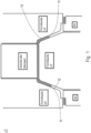
- FIGS 1a , 1b and 1c show a forming and cutting tool 1 according to the invention.
- the forming and cutting tool 1 has an upper tool 2 and a lower tool 3 for this purpose.
- a leading stamp 4 is arranged in the upper tool 2 itself, which clamps a circuit board 6 placed on a lower mold jaw 5 of the lower tool 3 onto it.
- the leading stamp 4 has previously been lowered.
- the board 6 is thus fixed in position and can no longer be moved, particularly in the horizontal direction H.
- Correspondingly opposite cutting edges 9 are now arranged on an upper mold jaw 7, which is part of the upper tool 2, and a lower sheet metal holder 8, which is part of the lower tool 3.
- the upper mold jaw 5 is trimmed at the edge 10.
- the edge trim 10 corresponds to the later external component edge 11, shown in Figure 1c .
- Cooling channels 19 can be seen, which can be provided for cooling all tool parts that are in contact with the formed circuit board to carry out press hardening.
- the cooling channels 19 are in the others Figures 1b - 3c not shown, but always provided on the tool.
- Figures 2a to 2c show a modification to Figures 1a to c.
- the edge trimming 10 takes place completely before the start of forming.
- a motor vehicle component 13 with a U-shaped cross-section is not produced here, but rather according to Figure 2c a motor vehicle component 13 with a hat-shaped cross section.
- Outwardly projecting flanges 14 protrude in the horizontal direction H.
- the lower sheet metal holder 8 in particular is made wider and also serves to form a mold cavity 12 with the upper tool 2 completely lowered to the bottom dead center.
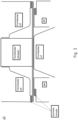
- Figures 3a to 3d show the production of a motor vehicle component 13 as a hat-shaped component analogously to Figure 2c .
- the edge trimming 10 is only carried out at a later point in time, i.e. approximately at a point in time in which at least 20 mm of distance in the press stroke direction 15 must be covered before reaching the bottom dead center of the forming tool.
- Figure 3b the inserted board 6 is fixed in position on the lower mold jaw by the leading stamp 4.
- the forming process has according to Figure 3b already started.
- the cutting tools or the opposing cutting edges 9 then carry out the cutting operation accordingly Figure 3c through.
- the forming process has progressed up to approximately 20% or the forming tool has been lowered in the press stroke direction 15 by approximately 20% of the distance to be covered by the press stroke.
- the edge trim 10 is already completely completed at this point, so that according to Figure 3d , with further lowering of the upper mold jaw and forming in connection with the lower sheet metal holder 8, the motor vehicle component 13 is then produced with flanges 14 projecting outwards in the horizontal direction H in the mold cavity 12.
- Figure 4 shows again two prefabricated circuit board blanks.
- a Tailor Welded Blank There are two board areas 6a and 6b with different wall thicknesses.
- the board areas 6a and 6b have an offset 16 to one another. Due to the circumferential edge trim 10, this offset 16 can be neglected, since a not in Figure 4a more closely adjusted circumferential edge is recut again in the course of the method according to the invention and no final edge trimming 10 or similar would have to be carried out.
- a circuit board 6 is also shown as a tailor welded blank.
- a weld seam 17 connecting the two board areas 6a and 6b has a lateral protruding weld seam projection 18. In the case of the circumferential edge trimming 10, this weld seam projection 18 is also cut off.
Landscapes
- Engineering & Computer Science (AREA)
- Mechanical Engineering (AREA)
- Chemical & Material Sciences (AREA)
- Crystallography & Structural Chemistry (AREA)
- Materials Engineering (AREA)
- Metallurgy (AREA)
- Organic Chemistry (AREA)
- Physics & Mathematics (AREA)
- Thermal Sciences (AREA)
- Shaping Metal By Deep-Drawing, Or The Like (AREA)
Abstract
Description
- Die vorliegende Erfindung betrifft ein Verfahren zur Herstellung eines Kraftfahrzeugbauteils durch Warmumformen und Warmschneiden gemäß den Merkmalen im Patentanspruch 1
- Aus dem Stand der Technik sind Warmumformverfahren von Blechplatinen hinreichend bekannt. Insbesondere ist das Warmumformen und Presshärten bekannt. Hierzu wird eine Blechplatine aus einer härtbaren Stahllegierung auf eine Temperatur über den Ac1- oder Ac3-Punkt erwärmt. Die so erwärmte Platine wird dann in ein Umformwerkzeug eingelegt und im warmen Zustand umgeformt. Im Anschluss wird das Umformwerkzeug bei einem direkten Warmformprozess zugehalten und rasch abgekühlt, so dass die umgeformte Platine gehärtet wird. Hierbei sind Zugfestigkeiten größer 1400 MPa nach dem Stand der Technik problemlos möglich. Die Besonderheit besteht darin, dass das gehärtete Werkstoffgefüge dann nur mit größerem Aufwand mechanisch nachbearbeitet werden kann. Zu diesem größeren Aufwand gehört beispielsweise ein Randbeschnitt. Der Randbeschnitt wird zur Erreichung einer besonders hohen Präzision des Bauteils meist nach dem Umformverfahren durchgeführt. Die Bauteilpräzision ist dadurch hinsichtlich der äußeren Kontur besonders genau. Problematisch ist jedoch, dass die bereits gehärtete Platine nur mit großem konstruktivem Aufwand und hohem abrasiven Verschleiß des Werkzeuges werden kann. Auch ein Laserschneiden führt zu einem hohen Kostenaufwand in der Fertigung bzw. Herstellung des Bauteils. Ein Kaltbeschnitt an gehärteten Bauteilen ist hinsichtlich (Mikro- )Rissgefahr nicht zu empfehlen.
- Die Problematik des Randbeschnitts wird unter Umständen als eine weitere Besonderheit darin verstärkt, wenn die Platinen unterschiedliche Wandstärken haben, insbesondere beispielsweise bei Tailor Welded Blanks (TWB), Platinen, die aus unterschiedlichen Wandstärken oder Stahllegierungen zusammengeschweißt sind. Schweißnahtüberstände, Schweißnahteinfall (Kerbe nach innen) über die Plantinenrandkontur hinaus oder auch ein Platinenversatz zwischen den beiden miteinander verbundenen Platinen sind problematisch und bedürfen meist eines Nachbeschnittes nach dem Zusammenschweißen der TWB.
- Aufgabe der vorliegenden Erfindung ist es, eine Möglichkeit aufzuzeigen, besonders kosteneffizient und gleichzeitig mit gesteigerter Präzision ein Bauteil durch Warmumformen herzustellen.
- Die zuvor genannte Aufgabe wird erfindungsgemäß mit einem Verfahren zur Herstellung eines Kraftfahrzeugbauteils durch Warmumformen und Warmschneiden mit den Merkmalen im Anspruch 1 gelöst. Vorteilhafte Weiterbildungen sind in den abhängigen Ansprüchen beschrieben.
- Das erfindungsgemäße Verfahren dient zur Herstellung eines Kraftfahrzeugbauteils. Die Kraftfahrzeugbauteile können beispielsweise eine Kraftfahrzeug-B-Säule, generell eine Kraftfahrzeugsäule, ein Tunnel, ein Bumper bzw. Stoßfängerträger oder ähnliches sein. Insbesondere sind so auch im Querschnitt wenigstens teilweise U-förmige, flanschlose Verstärkungsbauteile herstellbar, wie sie häufig als Einlegebauteile bzw. Patches zur Anwendung kommen, um o.g. Bauteile innen oder außen zu verstärken und eine lokale Doppelblechlage ausbilden. Diese werden durch Warmumformen und Warmschneiden, und optionales Presshärten in einem kombinierten Werkzeug hergestellt. Alles wird in einem Pressenhub durchgeführt.
- Das erfindungsgemäße Verfahren weist folgende Verfahrensschritte auf:
- Bereitstellen einer Platine aus einer insbesondere härtbaren Stahlblechlegierung,
- Vollständiges Erwärmen auf eine Temperatur größer Ac1, insbesondere größer Ac3,
- Einlegen in ein kombiniertes Umform- und Schneidewerkzeug,
- Fixieren der eingelegten Platine in dem Umform- und Schneidewerkzeug durch einen im Innenbereich des Werkzeuges angeordneten Stempel,
- Zumindest teilweise umlaufender Randbeschnitt vor Umformbeginn oder während eines Zeitraumes bis zu 50 % des Umformfortschrittes und/oder mindestens 20 %, bevorzugt mehr als 30 % des Pressenhubes vor dem unteren Totpunkt,
- Warmumformen in einem Pressenhub mit dem Randbeschnitt und Presshärten.
- Erfindungsgemäß zeichnet sich das Verfahren somit dadurch aus, dass die eingelegte Platine bereits vor Umformbeginn bzw. in der ersten Zeit des Umformens durchgeführt und der Beschnitt in diesem Zeitraum abgeschlossen ist.
- Es findet ausschließlich eine vertikale Schneidbewegung am Randbeschnitt statt. Das Schneidwerkzeug selber ist ausschließlich durch den Pressenhub selbst angetrieben. Es gibt keine weiteren Aktivantriebe ausschließlich für das Schneidwerkzeug. Es gibt auch keine Keilquerschieber. Ein Beschnitt in Horizontalrichtung findet nicht statt.
- Durch diese erfindungsgemäßen Maßnahmen ist es möglich, im Querschnitt C-förmige bzw. hutförmige Bauteile mit hohen Toleranzanforderungen zu fertigen. Ferner können gerade auch Bauteile hergestellt werden aus Tailor Welded Blanks bzw. Platinen mit unterschiedlichen Bereichen mit verschiedener Wandstärke. Es muss hier insbesondere kein Nachbeschnitt als Toleranzbeschnitt durchgeführt werden. Es entfallen ebenfalls Einlegetoleranzen gegenüber einem separaten Voreinlegen in das Warmumformwerkzeug sowie einem vorher erfolgendem reinen Platinenbeschnitt.
- Weiterhin ist es möglich, das im Querschnitt U-förmige oder C-förmige Umformbauteile hergestellt werden können, mithin flanschlose Bauteile, welche aufgrund der vertikalen Orientierung der U-förmigen bzw. C-förmigen Schenkel nach Abschluss des Umformvorganges nicht oder nur mit hohem Aufwand in einer Presse beschneidbar wären.
- Insbesondere sieht das Verfahren vor, dass die Platine in das Warmumformwerkzeug eingelegt wird bei einer Temperatur größer 500° C, insbesondere größer 550° C. Bevorzugt kann die Platine auch bei einer Temperatur größer AC1- oder größer AC3-Temperatur in das Warmumformwerkzeug eingelegt werden. Die Ac1 Temperatur beträgt je nach verwendeter Stahllegierung mehr als 700° C, die Ac3 Temperatur mehr als 900° C.
- Damit die Platine insbesondere lagefixiert ist, ist an dem Oberwerkzeug ein, dem Oberwerkzeug vorauseilender Stempel angeordnet. Die in das Warmumformwerkzeug eingelegte Platine ist insbesondere auf einer unteren Formbacke abgelegt. Der Stempel wird dann auf die Platine abgesenkt und klemmt die Platine zwischen Stempel und unterer Formbacke lagefixiert ein. Sodann wird der Warmschneidevorgang durchgeführt. Dies kann vor Beginn des eigentlichen Umformvorganges erfolgen.
- Der Warmschneidevorgang wird insbesondere als zumindest teilweiser, insbesondere vollständig umlaufender Randbeschnitt der Platine durchgeführt. Hierzu ist ein außen umlaufendes Schneidwerkzeug an dem eigentlichen Warmumformwerkzeug vorgesehen. Der Randbeschnitt kann auch vollständig derart erfolgen, dass zunächst ein teilweise umlaufender Platinenzuschnitt erfolgt, dies insbesondere vor dem Erwärmen der Platine. Während des Warmschneidens in dem hiesigen Umformwerkzeug erfolgt dann der restliche Randbeschnitt, so dass in Summe ein vollständig umlaufender Randbeschnitt durchgeführt ist. Insbesondere ist kein nachträglicher Randbeschnitt mehr nötig. Insbesondere wird auch kein Lasern bzw. Hartschneiden erforderlich.
- Das Schneidwerkzeug kann vollständig relativ zu Oberwerkzeug und Unterwerkzeug angeordnet sein. Das Schneidwerkzeug kann jedoch auch in das Oberwerkzeug und/oder das Unterwerkzeug, mithin in eine obere Formbacke und/oder in eine untere Formbacke integriert sein.
- Alternativ zu einem vollständigen Randbeschnitt vor Beginn des Umformens ist es auch möglich, dass der Randbeschnitt in einer ersten Zeit bzw. ersten Phase des Umformvorganges durchgeführt wird. Insbesondere ist der Randbeschnitt durchgeführt, wenn sich die Platine selbst noch vollständig in einem ebenen horizontalen Zustand oder geringen Umformgrad befindet. Dies ist insbesondere während eines Zeitraumes von weniger als 50 %, insbesondere weniger als 30 %, insbesondere weniger als 20 %, des Umformfortschrittes.
- Alternativ oder ergänzend kann dieser Zeitraum auch bezogen werden auf den insgesamt erfolgten Pressenhub von Oberwerkzeug und Unterwerkzeug zueinander. Insbesondere ist der Schneidvorgang begonnen und abgeschlossen, mindestens 20 %, bevorzugt mehr als 30 %, insbesondere mehr als 50 % des Pressenhubes vor Erreichen des unteren Totpunktes, mithin vollständig geschlossenem Umformwerkzeug. Dies bedeutet, für den Fall von 50 %, dass der Randbeschnitt abgeschlossen ist, wenn sich das Oberwerkzeug auf das Unterwerkzeug absenkt, bezogen auf den gesamten Pressenhub, dass dieser maximal 50 % fortgeschritten ist und insbesondere bevor der Pressenhub den unteren Totpunkt des Umformwerkzeuges erreicht.
- Im Anschluss an den Randbeschnitt wird dann der Warmumformvorgang durchgeführt bzw. abgeschlossen und es findet ein optionales Presshärten statt, insbesondere, wenn eine härtbare Stahllegierung verwendet wird.
- Der Randbeschnitt durchtrennt die Platine insbesondere vollständig in ihrer Wandstärke.
- Der Randbeschnitt wird insbesondere bei einer Temperatur von 550° bis 700° C durchgeführt. Es hat sich erfindungsgemäß herausgestellt, dass bei dieser Temperatur, je nach verwendeter Stahllegierung, ein Optimum aus Schneidfähigkeit des Stahls und abrasivem Verschleiß an den Schneidwerkzeugen ergibt, insbesondere auch in dem sich einstellenden Werkstoffgefüge an der Schneidkante.
- Ist der Randbeschnitt durchgeführt, so wird insbesondere die umzuformende, beschnittene Platine in das Innere des sich ergebenden Formhohlraumes eingezogen. Die eventuell abgebogenen Schenkel des sich ergebenden Kraftfahrzeugbauteils bzw. Umformbauteils können dann vertikal orientiert verlaufen, so dass ggf. kein vertikal orientierter Beschnitt durchführbar wäre.
- Dies wird durch einen vorauseilenden Randbeschnitt im horizontalen Zustand der Platine erfindungsgemäß gelöst.
- Insbesondere ist der Randbeschnitt abgeschlossen, mindestens 20 mm bevorzugt mehr als 30 mm, insbesondere mehr als 50 mm, ganz besonders bevorzugt mehr als 80 mm und insbesondere mehr als 100 mm vor Erreichen des unteren Totpunktes des Warm umformwerkzeuges.
- Im Zuge dieses Schutzrechts wird für das Umform- und Schneidewerkzeug auch der Begriff Warmumformwerkzeug und Warmschneidewerkzeug verwendet.
- Weitere Vorteile, Merkmale, Eigenschaften, Aspekte der vorliegenden Erfindung sind Gegenstand der nachfolgenden Beschreibung. Diese dienen dem einfacheren Verständnis der Erfindung. Bevorzugte Ausgestaltungsvarianten sind in schematischen Figuren dargestellt. Es zeigen:
- Figur 1a bis 1c
- ein erfindungsgemäßes Umform- und Schneidewerkzeug
- Figur 2a bis 2c
- Abwandlungen zu
Figuren 1a bis 1c - Figur 3a bis 3d
- die Herstellung eines Kraftfahrzeugbauteils 13 als hutförmiges Bauteil
- Figur 4a + 4b
- zwei vorgefertigte Platinenbereiche
- In den Figuren werden für gleiche und ähnliche Bauteile dieselben Bezugszeichen verwendet, auch wenn eine wiederholte Aufzählung aus Vereinfachungsgründen entfällt.
-
Figuren 1a ,1b und1c zeigen ein erfindungsgemäßes Umform- und Schneidewerkzeug 1. Das Umform- und Schneidewerkzeug 1 weist dazu ein Oberwerkzeug 2 und ein Unterwerkzeug 3 auf. Im Oberwerkzeug 2 selbst ist ein vorauseilender Stempel 4 angeordnet, der eine auf einer unteren Formbacke 5 des Unterwerkzeugs 3 abgelegte Platine 6 auf dieser einklemmt. Der vorauseilende Stempel 4 ist zuvor abgesenkt worden. Die Platine 6 ist somit lagefixiert und kann insbesondere in Horizontalrichtung H nicht mehr verschoben werden. An einer oberen Formbacke 7, welche Bestandteil des Oberwerkzeuges 2 ist, sowie einen unteren Blechhalter 8, welcher Bestandteil des Unterwerkzeuges 3 ist, sind nunmehr korrespondierend gegenüberliegende Schneidkanten 9 angeordnet. - Durch weiteres Absenken, dargestellt in
Figur 1b , der oberen Formbacke 5 wird ein Randbeschnitt 10 durchgeführt. Der Randbeschnitt 10 entspricht dabei der späteren außen umlaufenden Bauteilkante 11, dargestellt inFigur 1c . - Zum Zeitpunkt von
Figur 1b hat der Umformvorgang selbst noch nicht begonnen. Der Randbeschnitt 10 ist jedoch vollständig durchgeführt. Durch weiteres Absenken der oberen Formbacke 7 wird der Blechhalter 8 relativ zur unteren Formbacke 5 abgesenkt. GemäßFigur 1c findet dann der Umformvorgang in einem sich ergebenden Formhohlraum 12 statt. Der Umformvorgang ist dargestellt abgeschlossen und resultiert in einem Querschnitt wenigstens längenabschnittsweise U-förmigen, flanschlosen Kraftfahrzeugbauteil 13. Das Kraftfahrzeugbauteil 13 ist hergestellt aus der umzuformenden Platine 6. Die Platine 6 ist dazu in einen Innenraum des Umformwerkzeugs bzw. in einen Innenraum des Formhohlraums 12 eingezogen worden. - In
Figur 1a sind Kühlkanäle 19 erkennbar, die zur Kühlung aller mit der umgeformten Platine in Kontakt stehenden Werkzeugteile zur Durchführung des Presshärten vorgesehen sein können. Die Kühlkanäle 19 sind in den anderenFiguren 1b - 3c nicht gezeigt, am Werkzeug aber stets vorgesehen. -
Figuren 2a bis 2c zeigen eine Abwandlung zuFiguren 1a bis c. Auch hier erfolgt der Randbeschnitt 10 vollständig vor dem Umformbeginn. Im Unterschied zuFigur 1c wird hier jedoch kein im Querschnitt U-förmiges Kraftfahrzeugbauteil 13 hergestellt, sondern gemäßFigur 2c ein im Querschnitt hutförmiges Kraftfahrzeugbauteil 13. Nach außen abstehende Flansche 14 stehen in Horizontalrichtung H ab. Hierzu ist insbesondere der untere Blechhalter 8 breiter ausgebildet und dient auch zur Bildung eines Formhohlraumes 12 bei vollständig im unteren Totpunkt abgesenkten Oberwerkzeug 2. -
Figuren 3a bis 3d zeigen die Herstellung eines Kraftfahrzeugbauteils 13 als hutförmiges Bauteil analog zuFigur 2c . Hier wird jedoch der Randbeschnitt 10 erst zu einem späteren Zeitpunkt durchgeführt, mithin ca. zu einem Zeitpunkt, in dem noch mindestens 20 mm vor Erreichen des unteren Totpunktes des Umformwerkzeuges an Weg in Pressenhubrichtung 15 zurückgelegt werden müssen. So wird auch hier gemäßFigur 3b die eingelegte Platine 6 durch den vorauseilenden Stempel 4 lagefixiert auf der unteren Formbacke. Der Umformvorgang hat jedoch gemäßFigur 3b bereits begonnen. Die Schneidwerkzeuge bzw. die sich gegenüberliegenden Schneidkanten 9 führen dann die Schneidoperation gemäßFigur 3c durch. Hier ist der Umformvorgang beispielsweise bis zu ca. 20 % fortgeschritten bzw. ist das Umformwerkzeug in Pressenhubrichtung 15 um ca. 20 % des zurückzulegenden Weges des Pressenhubes abgesenkt. Der Randbeschnitt 10 ist zu diesem Zeitpunkt bereits jedoch vollständig abgeschlossen, so dass gemäßFigur 3d , bei weiterem Absenken von oberer Formbacke sowie Umformung in Verbindung mit dem unteren Blechhalter 8 dann das Kraftfahrzeugbauteil 13 mit in Horizontalrichtung H nach außen abstehenden Flanschen 14 in dem Formhohlraum 12 hergestellt ist. -
Figur 4 zeigt nochmals zwei vorgefertigte Platinenzuschnitte. Im Falle vonFigur 4a eine Tailor Welded Blank. Es gibt zwei Platinenbereiche 6a und 6b mit unterschiedlicher Wandstärke. Die Platinenbereiche 6a und 6b haben einen Versatz 16 zueinander. Durch den umlaufenden Randbeschnitt 10 kann dieser Versatz 16 vernachlässigt werden, da ein nicht inFigur 4a näher eingestellter umlaufender Rand nochmals im Zuge des erfindungsgemäßen Verfahrens nachgeschnitten wird und kein endgültiger Randbeschnitt 10 oder ähnliches durchgeführt werden müsste. - Im Falle von
Figur 4b ist ebenfalls eine Platine 6 als Tailor Welded Blank gezeigt. Eine die beiden Platinenbereiche 6a und 6b verbindende Schweißnaht 17 weist einen seitliche überstehenden Schweißnahtüberstand 18 auf. Im Falle des umlaufenden Randbeschnitts 10 wird auch dieser Schweißnahtüberstand 18 abgeschnitten. -
- 1 -
- Umform- und Schneidwerkzeug
- 2 -
- Oberwerkzeug
- 3 -
- Unterwerkzeug
- 4 -
- Stempel
- 5 -
- untere Formbacke
- 6 -
- Platine
- 7 -
- obere Formback
- 8 -
- Blechhalter
- 9 -
- Schneidkante
- 10 -
- Randbeschnitt
- 11 -
- Bauteilkante
- 12 -
- Formhohlraum
- 13 -
- Kraftfahrzeugbauteil
- 14 -
- Flansch
- 15 -
- Pressenhubrichtung
- 16 -
- Versatz
- 17 -
- Schweißnaht
- 18 -
- Schweißnahtüberstand
- 19
- Kühlkanal
- 6a -
- Platinenbereich
- 6b -
- Platinenbereich
- H -
- Horizontalrichtung
Claims (10)
- Verfahren zur Herstellung eines Kraftfahrzeugbauteils (13) durch Warmumformen und Warmschneiden und Presshärten:• Bereitstellen einer Platine (6) aus einer härtbaren Stahlblechlegierung,• Vollständiges Erwärmen auf eine Temperatur größer Ac1, insbesondere größer Ac3,• Einlegen in ein kombiniertes Umform- und Schneidewerkzeug (1),• Fixieren der eingelegten Platine (6) in dem Umform- und Schneidewerkzeug (1) durch einen im Innenbereich des Werkzeuges angeordneten Stempel (4),• Zumindest teilweise umlaufender Randbeschnitt (10) vor Umformbeginn oder während eines Zeitraumes bis zu 50 % des Umformfortschrittes und/oder größer 20 %, bevorzugt mehr als 30 % des Pressenhubes vor dem unteren Totpunkt,• Warmumformen in einem Pressenhub mit dem Randbeschnitt (10) und Presshärten.
- Verfahren nach Anspruch 1, dadurch gekennzeichnet, dass der Randbeschnitt (10) vollständig umlaufend ausgeführt wird.
- Verfahren nach Anspruch 1 oder 2, dadurch gekennzeichnet, dass der Randbeschnitt (10) die Platine (6) vollständig in ihrer Wandstärke durchtrennt.
- Verfahren nach einem der vorhergehenden Ansprüche, dadurch gekennzeichnet, dass das Kraftfahrzeugbauteil (13) im Querschnitt U-förmig oder hutförmig ausgebildet wird.
- Verfahren nach einem der vorhergehenden Ansprüche, dadurch gekennzeichnet, dass der Randbeschnitt (10) bei 550° bis 750°C durchgeführt wird.
- Verfahren nach einem der vorhergehenden Ansprüche, dadurch gekennzeichnet, dass die umzuformende Platine (6) nach erfolgtem Beschnitt durch den weiteren Umformvorgang in das Innere des Umformwerkzeuges eingezogen wird.
- Verfahren nach einem der vorhergehenden Ansprüche, dadurch gekennzeichnet, dass ein TailorWelded Blank umgeformt wird, wobei die Platine (6) mindestens zwei Bereiche mit voneinander verschiedenen Wandstärken und/oder verschiedener Stahllegierungen aufweist.
- Verfahren nach einem der vorhergehenden Ansprüche, dadurch gekennzeichnet, dass der Randbeschnitt (10) mindestens 20 mm, bevorzugt 30 mm und besonders bevorzugt mehr als 100mm vor Erreichen des unteren Totpunktes durchgeführt wird.
- Verfahren nach einem der vorhergehenden Ansprüche, dadurch gekennzeichnet, dass der Stempel (4) die Platine (6) zum Fixieren auf eine untere Formbacke (5) des Werkzeuges drückt.
- Verfahren nach einem der vorhergehenden Ansprüche, dadurch gekennzeichnet, dass der Stempel, die Formbacke sowie alle weiteren Werkzeugteile, die mit der zum Kraftfahrzeugbauteil (13) umgeformten Platine (6) in Kontakt stehenden Werkzeugteile zum Presshärten aktiv gekühlt sind.
Priority Applications (4)
| Application Number | Priority Date | Filing Date | Title |
|---|---|---|---|
| EP22189765.5A EP4321271B1 (de) | 2022-08-10 | 2022-08-10 | Verfahren zur herstellung eines kraftfahrzeugbauteils durch warmumformen mit integriertem beschnitt |
| ES22189765T ES2991841T3 (es) | 2022-08-10 | 2022-08-10 | Procedimiento para la fabricación de un componente de vehículo de motor mediante conformado en caliente con recorte integrado |
| CN202310981894.6A CN117583478A (zh) | 2022-08-10 | 2023-08-04 | 通过热成型、热切割和冲压硬化生产机动车构件的方法 |
| US18/232,081 US20240123486A1 (en) | 2022-08-10 | 2023-08-09 | Method for producing a motor vehicle component by hot-forming with integrated cut |
Applications Claiming Priority (1)
| Application Number | Priority Date | Filing Date | Title |
|---|---|---|---|
| EP22189765.5A EP4321271B1 (de) | 2022-08-10 | 2022-08-10 | Verfahren zur herstellung eines kraftfahrzeugbauteils durch warmumformen mit integriertem beschnitt |
Publications (2)
| Publication Number | Publication Date |
|---|---|
| EP4321271A1 true EP4321271A1 (de) | 2024-02-14 |
| EP4321271B1 EP4321271B1 (de) | 2024-07-31 |
Family
ID=82898954
Family Applications (1)
| Application Number | Title | Priority Date | Filing Date |
|---|---|---|---|
| EP22189765.5A Active EP4321271B1 (de) | 2022-08-10 | 2022-08-10 | Verfahren zur herstellung eines kraftfahrzeugbauteils durch warmumformen mit integriertem beschnitt |
Country Status (4)
| Country | Link |
|---|---|
| US (1) | US20240123486A1 (de) |
| EP (1) | EP4321271B1 (de) |
| CN (1) | CN117583478A (de) |
| ES (1) | ES2991841T3 (de) |
Citations (4)
| Publication number | Priority date | Publication date | Assignee | Title |
|---|---|---|---|---|
| DE102011110597A1 (de) * | 2010-08-18 | 2012-07-26 | Elisabeth Braun | Warmumformvorrichtung mit Schneideeinrichtung |
| EP3072980A1 (de) * | 2015-03-26 | 2016-09-28 | weba Werkzeugbau Betriebs GmbH | Verfahren und vorrichtung zur herstellung eines partiell gehärteten formteils |
| DE102018215545B4 (de) * | 2018-09-12 | 2020-08-20 | Volkswagen Aktiengesellschaft | Verfahren zum Herstellen eines pressgehärteten Blechformteils und Presshärtewerkzeug |
| DE102020201407A1 (de) * | 2020-02-05 | 2021-08-05 | Volkswagen Aktiengesellschaft | Verfahren und Werkzeug zur Herstellung eines pressgehärteten und beschnittenen Blechformteils |
Family Cites Families (3)
| Publication number | Priority date | Publication date | Assignee | Title |
|---|---|---|---|---|
| RU2015129987A (ru) * | 2013-03-13 | 2017-04-17 | Магна Интернэшнэл Инк. | Обработка поковок |
| DE102015101668A1 (de) * | 2015-02-05 | 2016-08-11 | Benteler Automobiltechnik Gmbh | Zweifach fallendes Heiz- und Formwerkzeug sowie Verfahren zur Herstellung warmumgeformter und pressgehärteter Kraftfahrzeugbauteile |
| ES2827455T3 (es) * | 2016-02-25 | 2021-05-21 | Benteler Automobiltechnik Gmbh | Método de fabricación de un componente de automóvil con al menos dos zonas de resistencia mutuamente diferentes |
-
2022
- 2022-08-10 EP EP22189765.5A patent/EP4321271B1/de active Active
- 2022-08-10 ES ES22189765T patent/ES2991841T3/es active Active
-
2023
- 2023-08-04 CN CN202310981894.6A patent/CN117583478A/zh active Pending
- 2023-08-09 US US18/232,081 patent/US20240123486A1/en active Pending
Patent Citations (4)
| Publication number | Priority date | Publication date | Assignee | Title |
|---|---|---|---|---|
| DE102011110597A1 (de) * | 2010-08-18 | 2012-07-26 | Elisabeth Braun | Warmumformvorrichtung mit Schneideeinrichtung |
| EP3072980A1 (de) * | 2015-03-26 | 2016-09-28 | weba Werkzeugbau Betriebs GmbH | Verfahren und vorrichtung zur herstellung eines partiell gehärteten formteils |
| DE102018215545B4 (de) * | 2018-09-12 | 2020-08-20 | Volkswagen Aktiengesellschaft | Verfahren zum Herstellen eines pressgehärteten Blechformteils und Presshärtewerkzeug |
| DE102020201407A1 (de) * | 2020-02-05 | 2021-08-05 | Volkswagen Aktiengesellschaft | Verfahren und Werkzeug zur Herstellung eines pressgehärteten und beschnittenen Blechformteils |
Also Published As
| Publication number | Publication date |
|---|---|
| US20240123486A1 (en) | 2024-04-18 |
| ES2991841T3 (es) | 2024-12-05 |
| EP4321271B1 (de) | 2024-07-31 |
| CN117583478A (zh) | 2024-02-23 |
Similar Documents
| Publication | Publication Date | Title |
|---|---|---|
| DE102009003668B4 (de) | Vorrichtung und Verfahren zur Herstellung zumindest teilweise geschlossener Profile oder Halbzeuge aus einer Platine | |
| EP1986801B1 (de) | Verfahren und vorrichtung zum herstellen eines ausschnittes oder durchbruchs in der wandung eines nach dem innenhochdruck-umformverfahren ausgebildeten bauteils | |
| EP2802425B1 (de) | Vorrichtung und verfahren zum tiefziehen von schalenteilen mit integriertem kopf- und zargenbeschnitt | |
| EP3401032B1 (de) | Verbundwerkzeug und verfahren zur herstellung eines blechbauteils | |
| DE102009038896B4 (de) | Verfahren zur Herstellung eines aus einem ersten und zweiten Bauteil gefügten Strukturbauteils sowie Vorrichtung zur Durchführung des Verfahrens | |
| EP2512702A1 (de) | Verfahren und vorrichtung zur herstellung eines halbschalenteils | |
| EP2874765B1 (de) | Verfahren zum herstellen eines umgeformten und zumindest bereichsweise gehärteten metallblechbauteils sowie presshärtwerkzeug zum herstellen eines solchen bauteiles | |
| EP2432605A1 (de) | Verfahren zur herstellung eines metallbauteils aus einem warmverprägten ausgangsmaterial | |
| DE102018215545B4 (de) | Verfahren zum Herstellen eines pressgehärteten Blechformteils und Presshärtewerkzeug | |
| EP3088092B1 (de) | Warmumform- und presshärtewerkzeug sowie verfahren zum betreiben des warmumform- und presshärtewerkzeuges | |
| DE3423155A1 (de) | Verfahren zur herstellung einer verschlussplatteneinheit fuer einen schiebeverschluss | |
| DE19842750B4 (de) | Verfahren und Herstellung von tiefgezogenen Hohlteilen und Ziehwerkzeug | |
| DE102013019634A1 (de) | Herstellung eines Blechformteils mit lokalem elektromagnetischen Umformen des Blechmaterials zur Erzeugung einer Blechformteilkante | |
| WO2018127480A1 (de) | Verfahren zum herstellen von blechbauteilen und vorrichtung hierfür | |
| DE102005051403B3 (de) | Verfahren zur Herstellung eines Blechformteiles | |
| DE102017102356B3 (de) | Verfahren und Vorrichtung zum Herstellen eines Kragens an einem Werkstück | |
| DE102006026805A1 (de) | Vorrichtung und Verfahren zum Warmumformen eines Halbzeugs | |
| EP4321271B1 (de) | Verfahren zur herstellung eines kraftfahrzeugbauteils durch warmumformen mit integriertem beschnitt | |
| WO2005075279A1 (de) | Bautell mit einem verbindungsbereich, sowie verfahren und werkzeug zu seiner herstellung | |
| DE102006049146B4 (de) | Verfahren zur Herstellung einer aus mindestens zwei miteinander verbundenen Blechteilen bestehenden Baugruppe | |
| WO2019048025A1 (de) | Verfahren zur herstellung eines bauteils und werkzeug dafür | |
| DE19927101A1 (de) | Verfahren und Vorrichtung zum Clinchen | |
| DE3906957A1 (de) | Verfahren zur herstellung von rohrartigen bauteilen | |
| EP3509771B1 (de) | Verfahren und werkzeug zur herstellung von blechbauteilen | |
| EP1758698B1 (de) | Verfahren und vorrichtung zum blechformen und härten |
Legal Events
| Date | Code | Title | Description |
|---|---|---|---|
| STAA | Information on the status of an ep patent application or granted ep patent |
Free format text: STATUS: EXAMINATION IS IN PROGRESS |
|
| PUAI | Public reference made under article 153(3) epc to a published international application that has entered the european phase |
Free format text: ORIGINAL CODE: 0009012 |
|
| 17P | Request for examination filed |
Effective date: 20230427 |
|
| AK | Designated contracting states |
Kind code of ref document: A1 Designated state(s): AL AT BE BG CH CY CZ DE DK EE ES FI FR GB GR HR HU IE IS IT LI LT LU LV MC MK MT NL NO PL PT RO RS SE SI SK SM TR |
|
| GRAP | Despatch of communication of intention to grant a patent |
Free format text: ORIGINAL CODE: EPIDOSNIGR1 |
|
| STAA | Information on the status of an ep patent application or granted ep patent |
Free format text: STATUS: GRANT OF PATENT IS INTENDED |
|
| INTG | Intention to grant announced |
Effective date: 20240306 |
|
| GRAS | Grant fee paid |
Free format text: ORIGINAL CODE: EPIDOSNIGR3 |
|
| GRAA | (expected) grant |
Free format text: ORIGINAL CODE: 0009210 |
|
| STAA | Information on the status of an ep patent application or granted ep patent |
Free format text: STATUS: THE PATENT HAS BEEN GRANTED |
|
| AK | Designated contracting states |
Kind code of ref document: B1 Designated state(s): AL AT BE BG CH CY CZ DE DK EE ES FI FR GB GR HR HU IE IS IT LI LT LU LV MC MK MT NL NO PL PT RO RS SE SI SK SM TR |
|
| REG | Reference to a national code |
Ref country code: CH Ref legal event code: EP Ref country code: GB Ref legal event code: FG4D Free format text: NOT ENGLISH |
|
| REG | Reference to a national code |
Ref country code: DE Ref legal event code: R096 Ref document number: 502022001346 Country of ref document: DE |
|
| REG | Reference to a national code |
Ref country code: IE Ref legal event code: FG4D Free format text: LANGUAGE OF EP DOCUMENT: GERMAN |
|
| REG | Reference to a national code |
Ref country code: LT Ref legal event code: MG9D |
|
| REG | Reference to a national code |
Ref country code: NL Ref legal event code: MP Effective date: 20240731 |
|
| REG | Reference to a national code |
Ref country code: ES Ref legal event code: FG2A Ref document number: 2991841 Country of ref document: ES Kind code of ref document: T3 Effective date: 20241205 |
|
| PG25 | Lapsed in a contracting state [announced via postgrant information from national office to epo] |
Ref country code: PT Free format text: LAPSE BECAUSE OF FAILURE TO SUBMIT A TRANSLATION OF THE DESCRIPTION OR TO PAY THE FEE WITHIN THE PRESCRIBED TIME-LIMIT Effective date: 20241202 |
|
| PG25 | Lapsed in a contracting state [announced via postgrant information from national office to epo] |
Ref country code: PT Free format text: LAPSE BECAUSE OF FAILURE TO SUBMIT A TRANSLATION OF THE DESCRIPTION OR TO PAY THE FEE WITHIN THE PRESCRIBED TIME-LIMIT Effective date: 20241202 |
|
| PG25 | Lapsed in a contracting state [announced via postgrant information from national office to epo] |
Ref country code: NO Free format text: LAPSE BECAUSE OF FAILURE TO SUBMIT A TRANSLATION OF THE DESCRIPTION OR TO PAY THE FEE WITHIN THE PRESCRIBED TIME-LIMIT Effective date: 20241031 |
|
| PG25 | Lapsed in a contracting state [announced via postgrant information from national office to epo] |
Ref country code: FI Free format text: LAPSE BECAUSE OF FAILURE TO SUBMIT A TRANSLATION OF THE DESCRIPTION OR TO PAY THE FEE WITHIN THE PRESCRIBED TIME-LIMIT Effective date: 20240731 Ref country code: GR Free format text: LAPSE BECAUSE OF FAILURE TO SUBMIT A TRANSLATION OF THE DESCRIPTION OR TO PAY THE FEE WITHIN THE PRESCRIBED TIME-LIMIT Effective date: 20241101 Ref country code: PL Free format text: LAPSE BECAUSE OF FAILURE TO SUBMIT A TRANSLATION OF THE DESCRIPTION OR TO PAY THE FEE WITHIN THE PRESCRIBED TIME-LIMIT Effective date: 20240731 Ref country code: NL Free format text: LAPSE BECAUSE OF FAILURE TO SUBMIT A TRANSLATION OF THE DESCRIPTION OR TO PAY THE FEE WITHIN THE PRESCRIBED TIME-LIMIT Effective date: 20240731 |
|
| PG25 | Lapsed in a contracting state [announced via postgrant information from national office to epo] |
Ref country code: BG Free format text: LAPSE BECAUSE OF FAILURE TO SUBMIT A TRANSLATION OF THE DESCRIPTION OR TO PAY THE FEE WITHIN THE PRESCRIBED TIME-LIMIT Effective date: 20240731 |
|
| PG25 | Lapsed in a contracting state [announced via postgrant information from national office to epo] |
Ref country code: LV Free format text: LAPSE BECAUSE OF FAILURE TO SUBMIT A TRANSLATION OF THE DESCRIPTION OR TO PAY THE FEE WITHIN THE PRESCRIBED TIME-LIMIT Effective date: 20240731 |
|
| PG25 | Lapsed in a contracting state [announced via postgrant information from national office to epo] |
Ref country code: IS Free format text: LAPSE BECAUSE OF FAILURE TO SUBMIT A TRANSLATION OF THE DESCRIPTION OR TO PAY THE FEE WITHIN THE PRESCRIBED TIME-LIMIT Effective date: 20241130 |
|
| PG25 | Lapsed in a contracting state [announced via postgrant information from national office to epo] |
Ref country code: HR Free format text: LAPSE BECAUSE OF FAILURE TO SUBMIT A TRANSLATION OF THE DESCRIPTION OR TO PAY THE FEE WITHIN THE PRESCRIBED TIME-LIMIT Effective date: 20240731 |
|
| PG25 | Lapsed in a contracting state [announced via postgrant information from national office to epo] |
Ref country code: RS Free format text: LAPSE BECAUSE OF FAILURE TO SUBMIT A TRANSLATION OF THE DESCRIPTION OR TO PAY THE FEE WITHIN THE PRESCRIBED TIME-LIMIT Effective date: 20241031 |
|
| PG25 | Lapsed in a contracting state [announced via postgrant information from national office to epo] |
Ref country code: RS Free format text: LAPSE BECAUSE OF FAILURE TO SUBMIT A TRANSLATION OF THE DESCRIPTION OR TO PAY THE FEE WITHIN THE PRESCRIBED TIME-LIMIT Effective date: 20241031 Ref country code: PL Free format text: LAPSE BECAUSE OF FAILURE TO SUBMIT A TRANSLATION OF THE DESCRIPTION OR TO PAY THE FEE WITHIN THE PRESCRIBED TIME-LIMIT Effective date: 20240731 Ref country code: NO Free format text: LAPSE BECAUSE OF FAILURE TO SUBMIT A TRANSLATION OF THE DESCRIPTION OR TO PAY THE FEE WITHIN THE PRESCRIBED TIME-LIMIT Effective date: 20241031 Ref country code: NL Free format text: LAPSE BECAUSE OF FAILURE TO SUBMIT A TRANSLATION OF THE DESCRIPTION OR TO PAY THE FEE WITHIN THE PRESCRIBED TIME-LIMIT Effective date: 20240731 Ref country code: LV Free format text: LAPSE BECAUSE OF FAILURE TO SUBMIT A TRANSLATION OF THE DESCRIPTION OR TO PAY THE FEE WITHIN THE PRESCRIBED TIME-LIMIT Effective date: 20240731 Ref country code: IS Free format text: LAPSE BECAUSE OF FAILURE TO SUBMIT A TRANSLATION OF THE DESCRIPTION OR TO PAY THE FEE WITHIN THE PRESCRIBED TIME-LIMIT Effective date: 20241130 Ref country code: HR Free format text: LAPSE BECAUSE OF FAILURE TO SUBMIT A TRANSLATION OF THE DESCRIPTION OR TO PAY THE FEE WITHIN THE PRESCRIBED TIME-LIMIT Effective date: 20240731 Ref country code: GR Free format text: LAPSE BECAUSE OF FAILURE TO SUBMIT A TRANSLATION OF THE DESCRIPTION OR TO PAY THE FEE WITHIN THE PRESCRIBED TIME-LIMIT Effective date: 20241101 Ref country code: FI Free format text: LAPSE BECAUSE OF FAILURE TO SUBMIT A TRANSLATION OF THE DESCRIPTION OR TO PAY THE FEE WITHIN THE PRESCRIBED TIME-LIMIT Effective date: 20240731 Ref country code: BG Free format text: LAPSE BECAUSE OF FAILURE TO SUBMIT A TRANSLATION OF THE DESCRIPTION OR TO PAY THE FEE WITHIN THE PRESCRIBED TIME-LIMIT Effective date: 20240731 |
|
| PG25 | Lapsed in a contracting state [announced via postgrant information from national office to epo] |
Ref country code: DK Free format text: LAPSE BECAUSE OF FAILURE TO SUBMIT A TRANSLATION OF THE DESCRIPTION OR TO PAY THE FEE WITHIN THE PRESCRIBED TIME-LIMIT Effective date: 20240731 Ref country code: SM Free format text: LAPSE BECAUSE OF FAILURE TO SUBMIT A TRANSLATION OF THE DESCRIPTION OR TO PAY THE FEE WITHIN THE PRESCRIBED TIME-LIMIT Effective date: 20240731 Ref country code: RO Free format text: LAPSE BECAUSE OF FAILURE TO SUBMIT A TRANSLATION OF THE DESCRIPTION OR TO PAY THE FEE WITHIN THE PRESCRIBED TIME-LIMIT Effective date: 20240731 |
|
| PG25 | Lapsed in a contracting state [announced via postgrant information from national office to epo] |
Ref country code: LU Free format text: LAPSE BECAUSE OF NON-PAYMENT OF DUE FEES Effective date: 20240810 |
|
| PG25 | Lapsed in a contracting state [announced via postgrant information from national office to epo] |
Ref country code: MC Free format text: LAPSE BECAUSE OF FAILURE TO SUBMIT A TRANSLATION OF THE DESCRIPTION OR TO PAY THE FEE WITHIN THE PRESCRIBED TIME-LIMIT Effective date: 20240731 Ref country code: EE Free format text: LAPSE BECAUSE OF FAILURE TO SUBMIT A TRANSLATION OF THE DESCRIPTION OR TO PAY THE FEE WITHIN THE PRESCRIBED TIME-LIMIT Effective date: 20240731 |
|
| PG25 | Lapsed in a contracting state [announced via postgrant information from national office to epo] |
Ref country code: SK Free format text: LAPSE BECAUSE OF FAILURE TO SUBMIT A TRANSLATION OF THE DESCRIPTION OR TO PAY THE FEE WITHIN THE PRESCRIBED TIME-LIMIT Effective date: 20240731 Ref country code: IT Free format text: LAPSE BECAUSE OF FAILURE TO SUBMIT A TRANSLATION OF THE DESCRIPTION OR TO PAY THE FEE WITHIN THE PRESCRIBED TIME-LIMIT Effective date: 20240731 |
|
| REG | Reference to a national code |
Ref country code: DE Ref legal event code: R097 Ref document number: 502022001346 Country of ref document: DE |
|
| PLBE | No opposition filed within time limit |
Free format text: ORIGINAL CODE: 0009261 |
|
| STAA | Information on the status of an ep patent application or granted ep patent |
Free format text: STATUS: NO OPPOSITION FILED WITHIN TIME LIMIT |
|
| REG | Reference to a national code |
Ref country code: BE Ref legal event code: MM Effective date: 20240831 |
|
| 26N | No opposition filed |
Effective date: 20250501 |
|
| PG25 | Lapsed in a contracting state [announced via postgrant information from national office to epo] |
Ref country code: BE Free format text: LAPSE BECAUSE OF NON-PAYMENT OF DUE FEES Effective date: 20240831 |
|
| PG25 | Lapsed in a contracting state [announced via postgrant information from national office to epo] |
Ref country code: FR Free format text: LAPSE BECAUSE OF NON-PAYMENT OF DUE FEES Effective date: 20240930 |
|
| PG25 | Lapsed in a contracting state [announced via postgrant information from national office to epo] |
Ref country code: IE Free format text: LAPSE BECAUSE OF NON-PAYMENT OF DUE FEES Effective date: 20240810 |
|
| PG25 | Lapsed in a contracting state [announced via postgrant information from national office to epo] |
Ref country code: SE Free format text: LAPSE BECAUSE OF FAILURE TO SUBMIT A TRANSLATION OF THE DESCRIPTION OR TO PAY THE FEE WITHIN THE PRESCRIBED TIME-LIMIT Effective date: 20240731 |
|
| PGFP | Annual fee paid to national office [announced via postgrant information from national office to epo] |
Ref country code: ES Payment date: 20250926 Year of fee payment: 4 |
|
| PGFP | Annual fee paid to national office [announced via postgrant information from national office to epo] |
Ref country code: DE Payment date: 20250826 Year of fee payment: 4 |
|
| PGFP | Annual fee paid to national office [announced via postgrant information from national office to epo] |
Ref country code: AT Payment date: 20251020 Year of fee payment: 4 |
|
| PGFP | Annual fee paid to national office [announced via postgrant information from national office to epo] |
Ref country code: CZ Payment date: 20250806 Year of fee payment: 4 |
|
| PG25 | Lapsed in a contracting state [announced via postgrant information from national office to epo] |
Ref country code: CY Free format text: LAPSE BECAUSE OF FAILURE TO SUBMIT A TRANSLATION OF THE DESCRIPTION OR TO PAY THE FEE WITHIN THE PRESCRIBED TIME-LIMIT; INVALID AB INITIO Effective date: 20220810 |
|
| PG25 | Lapsed in a contracting state [announced via postgrant information from national office to epo] |
Ref country code: HU Free format text: LAPSE BECAUSE OF FAILURE TO SUBMIT A TRANSLATION OF THE DESCRIPTION OR TO PAY THE FEE WITHIN THE PRESCRIBED TIME-LIMIT; INVALID AB INITIO Effective date: 20220810 |
|
| REG | Reference to a national code |
Ref country code: CH Ref legal event code: H13 Free format text: ST27 STATUS EVENT CODE: U-0-0-H10-H13 (AS PROVIDED BY THE NATIONAL OFFICE) Effective date: 20260324 |
|
| PG25 | Lapsed in a contracting state [announced via postgrant information from national office to epo] |
Ref country code: CH Free format text: LAPSE BECAUSE OF NON-PAYMENT OF DUE FEES Effective date: 20250831 |