EP4321106A2 - Instrument chirurgical - Google Patents
Instrument chirurgical Download PDFInfo
- Publication number
- EP4321106A2 EP4321106A2 EP23218944.9A EP23218944A EP4321106A2 EP 4321106 A2 EP4321106 A2 EP 4321106A2 EP 23218944 A EP23218944 A EP 23218944A EP 4321106 A2 EP4321106 A2 EP 4321106A2
- Authority
- EP
- European Patent Office
- Prior art keywords
- surgical instrument
- accessory
- shaft
- nose tube
- carriage
- Prior art date
- Legal status (The legal status is an assumption and is not a legal conclusion. Google has not performed a legal analysis and makes no representation as to the accuracy of the status listed.)
- Pending
Links
- 230000007246 mechanism Effects 0.000 title description 26
- 230000008878 coupling Effects 0.000 claims description 17
- 238000010168 coupling process Methods 0.000 claims description 17
- 238000005859 coupling reaction Methods 0.000 claims description 17
- 238000013519 translation Methods 0.000 claims description 9
- 230000013011 mating Effects 0.000 claims description 8
- 238000000034 method Methods 0.000 description 12
- 238000004891 communication Methods 0.000 description 10
- 238000005520 cutting process Methods 0.000 description 8
- 210000001519 tissue Anatomy 0.000 description 8
- 239000000463 material Substances 0.000 description 6
- 210000000988 bone and bone Anatomy 0.000 description 5
- 210000000689 upper leg Anatomy 0.000 description 5
- 241000721076 Echinodorus cordifolius Species 0.000 description 4
- 230000003287 optical effect Effects 0.000 description 4
- 238000001356 surgical procedure Methods 0.000 description 4
- 238000012546 transfer Methods 0.000 description 3
- 230000005355 Hall effect Effects 0.000 description 2
- 230000008901 benefit Effects 0.000 description 2
- 230000000694 effects Effects 0.000 description 2
- 230000006870 function Effects 0.000 description 2
- 238000005096 rolling process Methods 0.000 description 2
- 230000001133 acceleration Effects 0.000 description 1
- 238000002591 computed tomography Methods 0.000 description 1
- 230000009977 dual effect Effects 0.000 description 1
- 230000005484 gravity Effects 0.000 description 1
- 238000003384 imaging method Methods 0.000 description 1
- 239000000696 magnetic material Substances 0.000 description 1
- 238000002595 magnetic resonance imaging Methods 0.000 description 1
- 238000004519 manufacturing process Methods 0.000 description 1
- 239000003550 marker Substances 0.000 description 1
- 238000005259 measurement Methods 0.000 description 1
- 238000012986 modification Methods 0.000 description 1
- 230000004048 modification Effects 0.000 description 1
- 230000000399 orthopedic effect Effects 0.000 description 1
- 230000036316 preload Effects 0.000 description 1
- 230000008569 process Effects 0.000 description 1
- 238000012545 processing Methods 0.000 description 1
- 210000004872 soft tissue Anatomy 0.000 description 1
- 125000006850 spacer group Chemical group 0.000 description 1
- 238000009987 spinning Methods 0.000 description 1
- 238000003860 storage Methods 0.000 description 1
Images


Classifications
-
- A—HUMAN NECESSITIES
- A61—MEDICAL OR VETERINARY SCIENCE; HYGIENE
- A61B—DIAGNOSIS; SURGERY; IDENTIFICATION
- A61B17/00—Surgical instruments, devices or methods, e.g. tourniquets
- A61B17/16—Bone cutting, breaking or removal means other than saws, e.g. Osteoclasts; Drills or chisels for bones; Trepans
- A61B17/1613—Component parts
- A61B17/1615—Drill bits, i.e. rotating tools extending from a handpiece to contact the worked material
- A61B17/1617—Drill bits, i.e. rotating tools extending from a handpiece to contact the worked material with mobile or detachable parts
-
- A—HUMAN NECESSITIES
- A61—MEDICAL OR VETERINARY SCIENCE; HYGIENE
- A61B—DIAGNOSIS; SURGERY; IDENTIFICATION
- A61B17/00—Surgical instruments, devices or methods, e.g. tourniquets
- A61B17/16—Bone cutting, breaking or removal means other than saws, e.g. Osteoclasts; Drills or chisels for bones; Trepans
- A61B17/1613—Component parts
- A61B17/162—Chucks or tool parts which are to be held in a chuck
-
- A—HUMAN NECESSITIES
- A61—MEDICAL OR VETERINARY SCIENCE; HYGIENE
- A61B—DIAGNOSIS; SURGERY; IDENTIFICATION
- A61B17/00—Surgical instruments, devices or methods, e.g. tourniquets
- A61B17/16—Bone cutting, breaking or removal means other than saws, e.g. Osteoclasts; Drills or chisels for bones; Trepans
- A61B17/1613—Component parts
- A61B17/1622—Drill handpieces
- A61B17/1624—Drive mechanisms therefor
-
- A—HUMAN NECESSITIES
- A61—MEDICAL OR VETERINARY SCIENCE; HYGIENE
- A61B—DIAGNOSIS; SURGERY; IDENTIFICATION
- A61B17/00—Surgical instruments, devices or methods, e.g. tourniquets
- A61B17/16—Bone cutting, breaking or removal means other than saws, e.g. Osteoclasts; Drills or chisels for bones; Trepans
- A61B17/1613—Component parts
- A61B17/1626—Control means; Display units
-
- A—HUMAN NECESSITIES
- A61—MEDICAL OR VETERINARY SCIENCE; HYGIENE
- A61B—DIAGNOSIS; SURGERY; IDENTIFICATION
- A61B17/00—Surgical instruments, devices or methods, e.g. tourniquets
- A61B17/16—Bone cutting, breaking or removal means other than saws, e.g. Osteoclasts; Drills or chisels for bones; Trepans
- A61B17/1613—Component parts
- A61B17/1628—Motors; Power supplies
-
- A—HUMAN NECESSITIES
- A61—MEDICAL OR VETERINARY SCIENCE; HYGIENE
- A61B—DIAGNOSIS; SURGERY; IDENTIFICATION
- A61B17/00—Surgical instruments, devices or methods, e.g. tourniquets
- A61B17/32—Surgical cutting instruments
- A61B17/320016—Endoscopic cutting instruments, e.g. arthroscopes, resectoscopes
- A61B17/32002—Endoscopic cutting instruments, e.g. arthroscopes, resectoscopes with continuously rotating, oscillating or reciprocating cutting instruments
-
- A—HUMAN NECESSITIES
- A61—MEDICAL OR VETERINARY SCIENCE; HYGIENE
- A61B—DIAGNOSIS; SURGERY; IDENTIFICATION
- A61B34/00—Computer-aided surgery; Manipulators or robots specially adapted for use in surgery
- A61B34/20—Surgical navigation systems; Devices for tracking or guiding surgical instruments, e.g. for frameless stereotaxis
-
- A—HUMAN NECESSITIES
- A61—MEDICAL OR VETERINARY SCIENCE; HYGIENE
- A61B—DIAGNOSIS; SURGERY; IDENTIFICATION
- A61B34/00—Computer-aided surgery; Manipulators or robots specially adapted for use in surgery
- A61B34/25—User interfaces for surgical systems
-
- A—HUMAN NECESSITIES
- A61—MEDICAL OR VETERINARY SCIENCE; HYGIENE
- A61B—DIAGNOSIS; SURGERY; IDENTIFICATION
- A61B17/00—Surgical instruments, devices or methods, e.g. tourniquets
- A61B2017/00367—Details of actuation of instruments, e.g. relations between pushing buttons, or the like, and activation of the tool, working tip, or the like
- A61B2017/00398—Details of actuation of instruments, e.g. relations between pushing buttons, or the like, and activation of the tool, working tip, or the like using powered actuators, e.g. stepper motors, solenoids
-
- A—HUMAN NECESSITIES
- A61—MEDICAL OR VETERINARY SCIENCE; HYGIENE
- A61B—DIAGNOSIS; SURGERY; IDENTIFICATION
- A61B17/00—Surgical instruments, devices or methods, e.g. tourniquets
- A61B2017/00982—General structural features
- A61B2017/00991—Telescopic means
-
- A—HUMAN NECESSITIES
- A61—MEDICAL OR VETERINARY SCIENCE; HYGIENE
- A61B—DIAGNOSIS; SURGERY; IDENTIFICATION
- A61B34/00—Computer-aided surgery; Manipulators or robots specially adapted for use in surgery
- A61B34/20—Surgical navigation systems; Devices for tracking or guiding surgical instruments, e.g. for frameless stereotaxis
- A61B2034/2046—Tracking techniques
- A61B2034/2055—Optical tracking systems
- A61B2034/2057—Details of tracking cameras
-
- A—HUMAN NECESSITIES
- A61—MEDICAL OR VETERINARY SCIENCE; HYGIENE
- A61B—DIAGNOSIS; SURGERY; IDENTIFICATION
- A61B34/00—Computer-aided surgery; Manipulators or robots specially adapted for use in surgery
- A61B34/20—Surgical navigation systems; Devices for tracking or guiding surgical instruments, e.g. for frameless stereotaxis
- A61B2034/2046—Tracking techniques
- A61B2034/2059—Mechanical position encoders
-
- F—MECHANICAL ENGINEERING; LIGHTING; HEATING; WEAPONS; BLASTING
- F16—ENGINEERING ELEMENTS AND UNITS; GENERAL MEASURES FOR PRODUCING AND MAINTAINING EFFECTIVE FUNCTIONING OF MACHINES OR INSTALLATIONS; THERMAL INSULATION IN GENERAL
- F16H—GEARING
- F16H25/00—Gearings comprising primarily only cams, cam-followers and screw-and-nut mechanisms
- F16H25/18—Gearings comprising primarily only cams, cam-followers and screw-and-nut mechanisms for conveying or interconverting oscillating or reciprocating motions
- F16H25/20—Screw mechanisms
- F16H2025/2053—Screws in parallel arrangement driven simultaneously with an output member moved by the screws
Definitions
- the present disclosure relates generally to surgical instruments and, more particularly, to a surgical instrument with a telescoping nose mechanism for use in a system for tracking and controlling the surgical instrument.
- Tracking systems assist surgeons during surgeries that require the precise locating of instruments such as surgical instruments. Such surgeries include neurosurgery, spine, and orthopedic surgery.
- the tracking system tracks a position and orientation of the surgical instrument during the surgical procedure and often displays the position and/or orientation of the instrument on a monitor in conjunction with a preoperative image or an intraoperative image of the patient (preoperative images are typically prepared by MRI or CT scans, while intraoperative images may be prepared using a fluoroscope, low level x-ray or any similar device).
- the surgical instrument be used free hand without the aid of a cutting jig, guide arm or other constraining mechanism to establish the location to which the cutting implement at the end of the instrument is applied. See, for example, U.S. Patent No. 6,757,582 to Brisson et al.
- the tracking system typically employs a camera that detects a tracking device located on the surgical instrument.
- the tracking device has a plurality of optical markers such as light emitting diodes (LEDs) to determine the position and orientation of the surgical instrument.
- the position of the surgical instrument usually correlates to the coordinates of a working end of the instrument in three-dimensional space, the x, y, z or Cartesian coordinates, relative to the camera.
- the orientation of the surgical instrument means the pitch, roll, and yaw of the instrument. When both the position and the orientation of the surgical instrument are defined, the relative position of that instrument is known to the tracking system.
- the pencil-style hand-held surgical instrument is held by the hand of the user to perform a medical/surgical task on the tissue of the patient such as shape or remove tissue such as bone from a femur.
- the pencil-style handheld surgical instrument makes use of a telescoping nose for a depth degree of freedom.
- the pencil-style hand-held surgical instrument also makes use of two additional degrees of freedom which are provided via a pivoting gimbal mechanism.
- the instrument includes a portion having a threaded nose tube that translates linearly.
- a motor telescopes the nose tube using an elongated rotor with a long internal thread directly engaging the nose tube.
- the nose tube has an external thread on a proximal end, which directly interfaces with the rotor of the motor. As the rotor spins in one direction, the nose tube pulls in (due to the nose tube being keyed) and spinning in the opposite direction results in the nose tube pushing out.
- An example of such a pencil-style hand-held surgical instrument is disclosed in pending patent application U.S. Patent Application Publication No. 2013/0060278, filed August 31, 2012 , the entire disclosure of which is hereby expressly incorporated by reference.
- the surgical instrument comprises a hand-held portion configured to be manipulated by a user and a pivoting portion operatively coupled to the hand-held portion.
- the pivoting portion is configured to pivot with respect to the hand-held portion according to first and second degrees of freedom.
- the pivoting portion includes a telescoping nose mechanism including a nose tube, an intermediate unit having a carriage extending from the nose tube to enable linear translation of the nose tube, and a drive motor cooperating with the carriage to linearly translate the nose tube relative to the hand-held portion with respect to a third degree of freedom.
- the surgical instrument comprises a nose tube, a drive motor including a drive gear, and an intermediate unit coupled between the nose tube and the drive motor.
- the intermediate unit includes a plurality of leadscrews each being threaded and having a driven gear at one end.
- the intermediate unit includes a carriage being threaded for interfacing with the leadscrews.
- the drive gear is configured to interface with each of the driven gears to enable rotation of each of the leadscrews such that the carriage linearly translates along the leadscrews to enable telescoping of the nose tube.
- the surgical instrument comprises a pivoting portion and a shaft disposed in the pivoting portion.
- a first drive motor is disposed in the pivoting portion and is configured to rotate the shaft.
- a second drive motor is disposed in the pivoting portion and is configured to linearly translate the shaft.
- the second drive motor includes a rotor and a drive gear each defining an aperture extending therethrough to receive the shaft and to enable the shaft to freely rotate and linearly translate therethrough.
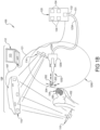
- a tracking and control system 100 used in conjunction with a surgical instrument 1200 is shown.
- the surgical instrument 1200 is used with an accessory 202.
- the accessory 202 has a rotatable shaft 203 and a distal end tip 204 at one end of the shaft 203.
- the accessory 202 is the component that performs a medical/surgical task or procedure on tissue of a patient.
- the types of accessories 202 that can be driven by the surgical instrument 1200 include shavers, drill bits, burs, ultrasonic tools, material delivery accessories, measurement devices, imaging accessories, or the like.
- the depicted accessory 202 is a bur (cutting accessory) that has at its distal end 204 a spherical bur head for removing bone and a proximal end 205 having a keyed double-D shape as illustrated in Figures 18A and 18B .
- the surgical instrument 1200 rotates the shaft 203 and distal end tip 204 of the accessory 202 and the tracking and control system 100 tracks the surgical instrument 1200 to keep the distal end tip 204 of the accessory 202 that is attached to the instrument 1200 in a desired relationship to a predefined boundary.
- distal means away from the user holding the surgical instrument 1200 and towards the tissue to which the instrument is applied.
- Proximal means towards the user holding the surgical instrument 1200 and away from the tissue to which the instrument is applied.
- the tracking and control system 100 controls the position of the distal end tip 204 of the accessory 202 relative to a home position on the surgical instrument 1200. It should be appreciated that this control prevents the distal end tip 204 of the accessory 202 from colliding with or breaching a boundary at the surgical site to which the accessory 202 is applied.
- the surgical instrument 1200 has a hand-held configuration.
- the hand-held configuration shown is a pencil-grip configuration.
- the surgical instrument 1200 includes a drill portion (also referred to as a pivoting portion), generally indicated at 1202, for example, referenced in Figures 2-6 , coupled to the accessory 202, and a hand-held portion 1204 held by the hand of the user, which provides two pivoting degrees of freedom of the drill portion 1202.
- the accessory 202 rotates, e.g., a bur, a drill bit, etc.
- the drill portion 1202 rotates the accessory 202 about a rotational axis R ( Figure 2 ).
- the rotational axis R moves relative to the hand-held portion 1204 in pitch and yaw.
- the drill portion 1202 telescopes the accessory 202 along a linear or depth axis Z relative to the home position.
- the depth axis "Z" and the rotational axis "R" are the same axis.
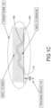
- the surgical instrument 1200 and accessory 202 are shown being used to shape a portion of a femur 102. It should be appreciated that the surgical instrument 1200 can be used to remove or otherwise treat other types of tissue, including soft tissue as well as other bones of the human body.
- the femur 102 has a target volume 104 of material that is to be removed by the distal end tip 204.
- the target volume 104 is defined by a boundary called the work boundary 106.
- This work boundary 106 defines the surface of the bone that should remain after the procedure.
- the tracking and control system 100 tracks and controls the surgical instrument 1200 to ensure that the distal end tip 204 only removes the target volume 104 of material and does not extend beyond the work boundary 106.
- the work boundary 106 in other embodiments may be defined by any shape or size and may include 2-D or 3-D shapes, lines, trajectories, surfaces, linear paths, non-linear paths, volumes, planes, bore holes, contours, and the like.
- the work boundary 106 can define a 2-D or 3-D boundary across which the surgical instrument 1200 should not cross.
- the work boundary 106 may define a line, path, trajectory or course along which the accessory 202 of the surgical instrument 1200 should travel. It should be appreciated that, in these cases, the work boundary 106 is also referred to as a work path, work trajectory or work course.
- the tracking and control system 100 includes a navigation unit 108.
- the navigation unit 108 tracks the positions and orientations of the femur 102 and surgical instrument 1200.
- the navigation unit 108 includes a camera 110 and a navigation computer 112 that receives and processes signals from the camera 110.
- the camera 110 is connected to the navigation computer 112 by a data connection 107.
- the data connection 107 may be an IEEE 1394 interface, which is a serial bus interface standard for high-speed communications and isochronous real-time data transfer. It should be appreciated that the data connection 107 could also use a company specific protocol.
- One camera 110 that can be incorporated into the tracking and control system 100 is the FlashPoint ® 6000 Camera sold by Stryker Corporation of Kalamazoo, Michigan.
- the camera 110 includes three separate high resolution CCD cameras (not shown).
- the CCD cameras detect infrared (IR) signals.
- the camera 110 is mounted to a stand (not shown) to position the camera 110 above the zone in which the procedure is to take place to provide the camera 110 with a field of view of trackers 114 and 116 attached to the hand-held portion 1204 and femur 102, respectively, that, ideally, is free from obstructions.
- Each tracker 114 and 116 has a plurality of optical markers in the form of light emitting diodes, such as three LEDs (not shown), that transmit infrared light to the camera 110.
- the optical markers are three or more light reflectors (not shown) for use with a camera unit (not shown) that transmits light that reflects off the light reflectors.
- additional trackers may be affixed to other bones, tissue, or other parts of the body, tools, or equipment.
- the trackers 114 and 116 may also be referred to as tracking devices 114 and 116, respectively.
- the navigation computer 112 can be a personal computer such as a laptop computer.
- the navigation computer 112 has a display 113, central processing unit (not shown), memory (not shown), and storage (not shown).
- the navigation computer 112 is loaded with software.
- the software converts the signals received from the camera 110 into data representative of the position and orientation of the objects to which trackers 114 and 116 are attached.
- an input device such as a mouse or other suitable pointer-input device and keyboard.
- the navigation computer 112 Based on the light captured signals forwarded from the camera 110, the navigation computer 112 determines the position of each optical marker and thus the position and orientation of the objects to which they are attached relative to the camera 110.
- An example of the camera 110, navigation computer 112, and trackers 114, 116 are shown in U.S. Patent No. 7,725,162 to Malackowski et al. , the disclosure of which is hereby incorporated by reference, including the camera, navigation computer and trackers and associated methods of operation and use disclosed therein.
- the tracking and control system 100 includes an instrument controller 120 in communication with the navigation computer 112 via a data connection 121.
- the instrument controller 120 may be or may include a computer.
- the data connection 121 may be an IEEE 1394 interface, which is a serial bus interface standard for high-speed communications and isochronous real-time data transfer. In another implementation, the data connection 121 could use a company specific protocol.
- the instrument controller 120 communicates with the surgical instrument 1200 by a data connection 123. It should be appreciated that, in some implementations, the navigation computer 112 and instrument controller 120 may be a single unit.
- the tracking and control system 100 includes a plurality of motor controllers 124 in communication with each of a plurality of motors of the surgical instrument 1200 via motor power connections 125.
- the instrument controller 120 is in communication with the motor controllers 124 via data connections 126.
- the data connection 126 may be a high-speed data communication protocol such as EtherCat. In another implementation, the data connection 126 could use a company specific protocol.
- the motor controllers 124 power and position actuators of the surgical instrument 1200 via the motor power connections 125. It should be appreciated that, in some implementations, the motor controllers 124 may be a single unit.
- the tracking and control system 100 may further include an instrument driver 130.
- the instrument driver 130 provides power to an accessory drive motor to be described of the drill portion 1202 to control the power and/or speed of the accessory 202.
- the power supply and control components internal to instrument driver 130 may be similar those in the surgical instrument control console described in U.S. Patent No.
- the instrument driver 130 is in communication with the instrument controller 120 via a data connection 131.
- the data connection 131 may be an IEEE 1394 interface, which is a serial bus interface standard for high-speed communications and isochronous real-time data transfer.
- the data connection 131 could use a company specific protocol. It should be appreciated that, in other implementations, the instrument driver 130 could be integrated into or part of the instrument controller 120.
- the tracking and control system 100 includes the instrument controller 120 in communication with the navigation computer 112 via a data connection 121.
- the instrument controller 120 includes or contains the motor controllers 124 and a power supply 132 for each of the motors of the surgical instrument 1200.
- the instrument controller 120 communicates with the surgical instrument 1200 by a data connection 123A.
- the makeup of the connection 123A may differ from that of Figure 1A and a common power connection 131 is required to power the plurality of motors of the surgical instrument 1200.
- This type of embodiment may also impact the type and amount of electronics embedded within the surgical instrument 1200.
- this embodiment may significantly reduce the size and number of connections between the surgical instrument 1200 and instrument controller 120.
- the instrument controller 120 may include a personal computer, etc.
- the instrument controller 120 defines a constraint boundary 111 that is located a predetermined distance from the work boundary 106 to define a buffer 105.
- the instrument controller 120 determines the position of the center of the distal end tip 204, relative to the constraint boundary 111 to control the surgical instrument 1200.
- the relative distance between the working boundary 106 and the constraint boundary 111 is a function, in part, of the geometry of the accessory 202. For example, if the accessory 202 includes the distal end tip 204 as a spherical bur head, the constraint boundary 111 is one-half the diameter of the bur head. It should be appreciated that, when the centroid of the bur head is on the constraint boundary 111, the bur's outer cutting surface is at the work boundary 106.
- the surgical instrument 1200 communicates with the instrument controller 120 via the data connection 123.
- the data connection 123 provides the path for the input and output required to control the surgical instrument 1200 based on the position and orientation data generated by the navigation computer 112 and transmitted to the instrument controller 120.
- the surgical instrument 1200 can be used in the tracking and control system 100 shown in Figures 1A and 1B as described above. As set forth above, the tracking and control system 100 tracks the positions and orientations of the target volume 104 and the surgical instrument 1200 to keep the distal end tip 204 of the accessory 202 at the target volume 104. It should be appreciated that the surgical instrument 1200 typically includes the data connection 123 for connection to the tracking and control system 100, and specifically to the instrument controller 120.
- the surgical instrument 1200 includes a distal assembly, also referred to as the drill portion 1202, and a proximal assembly, also referred to as the hand-held portion 1204.
- the hand-held portion 1204 is manipulated by the user, and in some embodiments, manually supported and moved by the user.
- the user operates the surgical instrument 1200 by grasping and supporting the hand-held portion 1204 and the surgical instrument 1200 is unsupported by other mechanical arms, frames, etc.
- the surgical instrument 1200 may be attached to a robotic arm or manipulator, which in some modes, enables the user to manually interface with the hand-held portion 1204 to control movement of the robotic arm or manipulator.
- a robotic arm or manipulator which in some modes, enables the user to manually interface with the hand-held portion 1204 to control movement of the robotic arm or manipulator.
- One example of such instrument is described in United States Patent Application Publication No.
- the accessory 202 is movably coupled to the hand-held portion 1204 by the drill portion 1202.
- the drill portion 1202 releasably holds the accessory 202 and drives the accessory 202 to perform the medical/surgical task on the tissue of the patient, and moves the accessory 202 in the linear or depth axis Z in a depth degree of freedom to prevent the distal end tip 204 of the accessory 202 from colliding with or breaching the work boundary 106 of the target volume 104 to which the accessory 202 is being applied.
- the two pivot degrees-of-freedom contained within the hand-held portion 1204, work in a coordinated fashion with the above-described linear or depth degree-of-freedom.
- the hand-held portion 1204 engages the drill portion 1202 and moves the drill portion 1202 to adjust the pitch and yaw of the accessory 202 to prevent the distal end tip 204 of the accessory 202 from colliding with or breaching the work boundary 106 of the target volume 104.
- pitch is the up-down angular orientation (i.e., the X-axis shown in the Figures) of the drill portion 1202 and accessory 202 relative to a horizontal plane through a center of a gimbal 1312 to be described and "yaw” is the right-left angular orientation (i.e., the Y-axis shown in the Figures) of the drill portion 1202 and accessory 202 relative to a vertical plane through the center of the gimbal 1312. It should be appreciated that the range of motion of the distal end tip 204 of the accessory 202 relative to the drill portion 1202 is defined by the tracking and control system 100.
- the hand-held portion 1204 includes an outer casing 1206 and the drill portion 1202 includes an outer casing 1208 that remains rotationally fixed about the Z-axis relative to the outer casing 1206 of the hand-held portion 1204.
- the drill portion 1202 also includes a bushing casing 1210 fixed to the outer casing 1208 and a movable nose tube 1212 that extends from the bushing casing 1210 and supports the accessory 202. It should be appreciated that the hand-held portion 1204 engages the drill portion 1202 and adjusts the pitch and yaw of the drill portion 1202 relative to the hand-held portion 1204 in the same manner as disclosed in U.S. Patent Application Publication No.
- the drill portion 1202 includes an accessory drive mechanism, generally indicated at 1214, coupled to the accessory 202 for rotating and providing torque to the accessory 202 about the rotational axis R.
- the drive mechanism 1214 includes a drive motor 1216, also referred to as an accessory drive motor, disposed in the outer casing 1208 for driving an intermediate shaft 1224, which drives an interconnecting shaft 1270 (also referred to as "bur shaft”), which finally drives the shaft 203 of the accessory 202.
- the drill portion 1202 and the accessory 202 move relative to the hand-held portion 1204 in a plurality of degrees of freedom.
- the surgical instrument 1200 includes a plurality of actuators, e.g., a linear drive motor 1226 to be described, yaw motor 1223, and pitch motor 1227, operatively coupled to the accessory 202 for moving the accessory 202 in a plurality of degrees of freedom relative to the hand-held portion 1204. It should be appreciated that, at least one of the actuators, and more specifically, the yaw motor 1223 and the pitch motor 1227, move the drive mechanism 1214 and the accessory drive motor 1216 in pitch and yaw relative to the hand-held portion 1204.
- the outer casing 1208 is movable by at least one of the actuators, e.g., the yaw motor 1223 in yaw and the pitch motor 1227 in pitch relative to the hand-held portion 1204. Motors are connected to the motor controllers 124.
- the linear drive motor 1226 may actuate in a linear or rotational manner.
- the yaw and pitch motors 1223, 1227 may be like those disclosed in U.S. Patent Application Publication No. 2013/0060278 , incorporated herein by reference, and may move the drill portion 1202 in yaw and pitch in the same manner.
- the plurality of actuators e.g., linear drive motor 1226, yaw motor 1223, and pitch motor 1227, are capable of moving the accessory 202 relative to the hand-held portion 1204 in at least three degrees of freedom including pitch, yaw, and depth.
- the accessory drive motor 1216 acts as a fourth degree-of-freedom by selectively controlling the rotational speed of the accessory 202.
- the drill portion 1202 supports the accessory 202 and one of the actuators and is movable by at least another of the actuators. Specifically, the drill portion 1202, and more specifically, the outer casing 1208, supports the linear drive motor 1226 and the accessory drive motor 1216.
- the linear drive motor 1226 translates the accessory 202 along the drill's depth axis Z.
- the drill portion 1202 is movable by the yaw motor 1223 and the pitch motor 1227.
- the yaw motor 1223 and pitch motor 1227 move the accessory drive motor 1216 and the linear drive motor 1226 in pitch and yaw relative to the hand-held portion 1204.
- the accessory drive motor 1216 can be controlled by the instrument driver 130 ( Figure 1A ) or the motor controller 124 ( Figure 1B ).
- the accessory drive motor 1216 includes an electromagnetic coil 1217 and a rotor 1218 that is rotatably coupled to the outer casing 1208 to drive the accessory 202.
- the rotor 1218 can include at least one bearing 1220 at each end operatively engaging the outer casing 1208 via the electromagnetic coil 1217 to rotatably couple the rotor 1218 to the outer casing 1208 and allow rotation of the rotor 1218 relative to the outer casing 1208.
- the electromagnetic coil 1217 rotates the rotor 1218.
- the rotor 1218 drives an intermediate shaft 1224 via a double "D" connection as illustrated in Figure 11B .
- the drill portion 1202 may include any suitable means internal to the accessory drive motor 1216 and/or the linear drive motor 1226 to determine and control the position of the accessory 202.
- the motors 1216, 1226 may be equipped with hall-effect sensors measuring signals based on the sensed magnet fields from the rotor and which vary as a function of the rotational position of the associated motor rotor.
- rotary position encoders or absolute angular position encoders may be used.
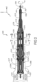
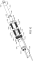
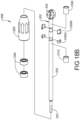
- the drill portion 1202 also includes a telescoping nose mechanism, generally indicated at 1222.
- the telescoping nose mechanism 1222 includes an intermediate shaft 1224 disposed in the outer casing 1208 and extending from the rotor 1218 for transmitting rotation from the accessory drive motor 1216 to the accessory 202 for driving the accessory 202.
- the telescoping nose mechanism 1222 also includes a linear drive motor, generally indicated at 1226, and a linear block (also referred to as an intermediate unit), generally indicated at 1228 cooperating with the linear drive motor 1226 to telescope or translate the nose tube 1212 along the linear or depth axis Z.
- the linear drive motor 1226 includes an electromagnetic coil 1229 and a rotor 1230 having an aperture 1232 extending axially therethrough to allow the intermediate shaft 1224 to extend through the linear drive motor 1226 and be rotatably connected to the accessory drive motor 1216.
- the rotor 1230 can include at least one or more bearing 1234 engaging the outer casing 1208 via the electromagnetic coil 1229 at one end and the linear block 1228 at the other axial end.
- the linear drive motor 1226 also includes a drive gear 1236 at one end of the rotor 1230 to engage the linear block 1228.
- the electromagnetic coil 1229 rotates the rotor 1230.
- the intermediate shaft 1224 has elongated flats 1225 at each axial end to form a double "D" connection.
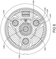
- the linear block 1228 includes a plurality of leadscrews 1238 extending axially and spaced circumferentially. In the embodiment illustrated, there are three (3) leadscrews 1238. Each of the leadscrews 1238 has a plurality of threads 1239 therealong. Each of the leadscrews 1238 includes a driven pinion gear 1240 at one end thereof. The pinion gear 1240 includes a plurality of teeth to engage the teeth of the rotor's drive gear 1236.
- the linear block 1228 also includes a carriage 1242 to move linearly or axially along the leadscrews 1238.
- the carriage 1242 extends from the nose tube 1212 and provides a mechanical interface between the leadscrews 1238 and the nose tube 1212.
- the carriage 1242 is integrally formed as part of the nose tube 1212 such that they form part of a common component.
- the carriage 1242 and the nose tube 1212 are separate components.
- the carriage 1242 includes threads 1247 to interface with the threads 1239 of the leadscrews 1238. The carriage 1242 may cooperate with the leadscrews 1238 according to various embodiments.
- the carriage 1242 includes a central aperture 1244 extending axially therethrough to receive the nose tube 1212.
- the carriage 1242 also includes a plurality of secondary apertures 1246 spaced radially from the central aperture 1244 and circumferentially and extending axially therethrough.
- the secondary apertures 1246 include the threads 1247 therein to engage the threads 1239 of the leadscrews 1238.
- the nose tube 1212 may have a flange 1248 extending radially to locate the carriage 1242 relative to the nose tube 1212 and a flanged bushing 1249 disposed in the nose tube 1212 and engaging the carriage 1242. It should be appreciated that all three pinion gears 1240 engaged with the drive gear 1236 results in coordinated motion of the three leadscrews 1238 as the linear drive rotor 1230 rotates.
- the carriage 1242 may not have the central aperture 1244 depending on factors such as whether the carriage 1242 and nose tube 1212 are formed of the same component, and the like.
- the secondary apertures 1246 may be replaced with alternative configurations, such as partially circular portions, rolling mechanisms (e.g., bearings), or the like, for interfacing with the threads 1239 of the leadscrews 1238.
- the carriage 1242 is axially trapped or fixed at the proximal end of the nose tube 1212.
- the carriage 1242 and the nose tube 1212 may be configured to exhibit tight axial compliance such that the carriage 1242 does not wobble relative to the nose tube 1212 in the depth Z-axis direction.
- This axial compliance may be zero or so tight that there is effectively no tolerance that needs to be accounted for.
- the nose tube 1212 and the carriage 1242 may be configured to enable relatively large radial compliance to adjust for tolerances.
- the radial compliance may be much greater than the tight axial compliance between the carriage 1242 and the nose tube 1212.
- Such radial compliance may be implemented in various manners.
- an inner diameter of the central aperture 1244 of the carriage 1242 is deliberately larger than the outer diameter of the nose tube 1212 to provide a gap therebetween and allow the carriage 1242 to move radially with respect to the nose tube 1212.
- the secondary apertures 1246 when present, may include an inner diameter being deliberately larger than the outer diameter of the leadscrews 1238.
- biasing members such as springs
- the carriage 1242 and/or nose tube 1212 may be comprised of or have coupled thereto deformable materials for accommodating the radial movement.
- the linear block 1228 also includes an end holder 1250 disposed about one end of the lead screws 1238.
- the end holder 1250 includes a central aperture 1252 extending axially therethrough to receive the nose tube 1212.
- the end holder 1250 also includes a plurality of secondary apertures 1254 spaced radially from the central aperture 1252 and circumferentially and extending axially therethrough.
- Each aperture 1254 includes a bearing 1256 to rotatably support one end of the leadscrews 1238.
- the end holder 1250 is disposed in the outer casing 1208 and is fixed relative thereto.
- the linear block 1228 also includes a housing 1258 disposed about the other end of the leadscrews 1238 and connected to the bearing 1234 disposed about the rotor 1230.
- the housing 1258 extends axially and is connected to the end holder 1250 by a plurality of fasteners 1260.
- the housing 1258 is disposed in the outer casing 1208 and is fixed relative thereto.
- the other end of the leadscrews 1238 are rotatably disposed in the housing 1250 by bearings 1262.
- the intermediate shaft 1224 is rotatably supported in the housing 1258 by a bearing 1264.
- the intermediate shaft 1224 is supported in three locations and the middle bearing 1264 is supported by dual O-rings 1265.
- the distal end of the intermediate shaft 1224 is rotatably supported and axially fixed to the nose tube 1212 by a bearing 1266 ( Figure 5 ). This results in the intermediate shaft 1224 following the position of the nose tube 1212 as it telescopes in and out.
- the linear block 1228 further includes a translation encoder 1268 disposed about the housing 1258 to sense the linear position of the carriage 1242. It should be appreciated that the translation encoder 1268 senses a position of the carriage 1242, which provides one method for the position of the nose tube 1212 and accessory 202 to be determined. This could be accomplished by placing a magnet on the carriage 1242 and one or more hall-efFect sensors along the housing 1258. Other techniques for measuring or determining the position of the nose tube 1212 and accessory 202 may be utilized, such as electromagnetic sensors, or the like.
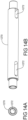
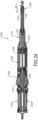
- the drive mechanism 1214 includes the interconnecting shaft 1270 disposed within the nose tube 1212 and interconnecting the distal end of the intermediate shaft 1224 and the proximal end 205 of the shaft 203 of the accessory 202.
- the interconnecting shaft 1270 has a double-D shape opening 1272 at each end as illustrated in Figure 14A but can be any suitable shape without departing from the scope of the present invention.
- Each end of the interconnecting shaft 1270 is supported in the nose tube 1212 by a bearing 1274.
- the double-D shaped openings 1272 are connected to the keyed ends of the shafts 1224 and 203 such that rotation of the intermediate shaft 1224 is transmitted to the accessory shaft 203. It should also be appreciated that the interconnecting shaft 1270 transmits torque from the intermediate shaft 1224 to the accessory shaft 203 of the accessory 202.
- the telescoping nose mechanism 1222 also includes a linear bushing 1276 disposed in the nose tube 1212.
- the bushing 1276 is generally cylindrical in shape with a generally circular cross-section.
- the bushing 1276 includes a central aperture 1278 extending axially therethrough to receive the nose tube 1212.
- the bushing 1276 also includes a plurality of internal channels or keyways 1280 extending radially from the central aperture and axially therealong for receiving the protrusions or external tabs 1282 of the nose tube 1212.
- Each internal keyway 1280 receives one of the external tabs 1282 of the nose tube 1212.
- the keyways 1280 extend parallel to the depth axis Z and are sized and shaped to restrain the external tabs 1282 to movement along the depth axis Z.
- the bushing 1276 may be formed from a different type of material than the casing 1208.
- the bushing 1276 may be formed of a material that provides a low-friction interface with the nose tube 1212 and may be formed of a non-magnetic material to allow for position sensing. It should be appreciated that the external tabs 1282 of the nose tube 1212 are keyed to the linear bushing 1276 to prevent rolling about its axis. It should also be appreciated that the bushing 1276 is fixed relative to the outer casing 1210.
- the telescoping nose mechanism 1222 includes the nose tube 1212 extending axially and telescopes relative to the outer casing 1210.
- the nose tube 1212 is moved by the linear block 1228 along the depth axis Z relative to the outer casing 1210. It should be appreciated that, the external tabs 1282 slide in the keyways 1280, respectively, as the nose tube 1212 moves along the depth axis Z.
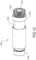
- the telescoping nose mechanism 1222 includes an adapter or insert 1283 connected or inserted to the distal end 1284 of the nose tube 1212 by a suitable mechanism such as press-fitting.
- the insert 1283 has an external threaded portion 1285 at a distal end.
- the telescoping nose mechanism 1222 includes one or more bearings 1286 disposed inside the nose tube 1212 and configured to engage and rotatably support the accessory shaft 203 of the accessory 202.
- the telescoping nose mechanism 1222 also includes a plurality of spacers 1288 and 1294 disposed inside the nose tube 1212 and spaced axially by a spring 1292 therebetween to preload the numerous bearings within the nose tube 1212.
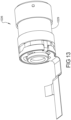
- the accessory 202 may include a coupling ("bur") assembly 1298 to rotatably couple the accessory shaft 203 of the accessory 202 to the nose tube 1212 via the insert 1283 so that the accessory 202 rotates about the rotational axis R upon rotation relative to the nose tube 1212.
- the coupling assembly 1298 includes a connector 1300 having a bore 1302 extending axially therethrough with internal threads 1304 at one end to retain the coupling assembly 1298 to the threaded end 1285 of the insert 1283.
- the coupling assembly 1298 also includes one or more bearings 1306 disposed in the bore 1302 between the connector 1300 and the accessory shaft 203 of the accessory 202 to allow rotation therebetween.
- the coupling assembly 1298 also includes flanged clam shells 1309A and 1309B to trap or capture inner races of the bearings 1306 in place relative to the accessory shaft 203.
- the coupling assembly 1298 also includes sleeves 1308 and 1310 disposed on the accessory shaft 203 about the flanged clam shells 1309A and 1309B. It should be appreciated that the above embodiment of the coupling assembly 1298 should not be considered limiting. It should also be appreciated that alternative methods for securing the coupling assembly 1298 to the nose tube 1212 are permissible as well as alternative manufacturing methods for securing the inner races of the bearing 1306 in place relative to the accessory shaft 203.
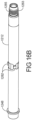
- nose tube 1212 supports the accessory 202 and is movable relative to the casings 1208 and 1210 in translation along the depth axis Z, i.e., the nose tube 1212, which is typically cylindrical, adjusts the position of the accessory 202 along the depth axis Z.
- Figures 20-25 show the nose tube 1212 moved to different locations relative to the outer casings 1208 and 1210 along the depth axis Z. Specifically, in Figure 20 the nose tube 1212 is nearly fully retracted, and in Figure 24 , the nose tube 1218 is nearly fully extended. Figures 21-23 show a position between those shown in Figures 20 and 24 . Specifically, Figure 22 shows the nose tube 1212 in a "home" position. Figure 21 shows the nose tube 1212 in an intermediate position between the fully retracted position and the home position. Figure 23 shows the nose tube 1212 in an intermediate position between the home position and the fully extended position. Figure 25 shows all of the positions illustrated in Figures 20-25 .
- the drill portion 1202 includes a gimbal 1312 to support movement of the accessory 202 in at least two pivoting degrees of freedom relative to the hand-held portion 1204.
- the accessory 202 is adjustable in pitch and yaw about the gimbal 1312.
- the gimbal 1312 is fixed along the depth axis Z relative to the hand-held portion 1204. It should be appreciated that the nose tube 1212 translates linearly relative to the gimbal 1312 along the drill's depth axis Z.
- the gimbal 1312 is integrated into the outer casing 1208 of the drill portion 1202 so the drill portion 1202 and the accessory 202 are able to pivot relative to the hand-held portion 1204.
- the gimbal 1312 may be located around the approximate center of gravity G of drill portion 1202 to minimize the mass moment of inertia of the drill portion 1202 as the drill portion 1202 is pivoted to maximize the angular acceleration for a given supplied torque.
- a trigger or foot pedal, or alternatively a button, can be supported by the outer casing 1206 of the hand-held portion 1204 to power the accessory drive motor 1214, i.e., to selectively supply power to or not supply power to the accessory 202.
- the surgical instrument 1200 may include a sensor (not shown) disposed inside the surgical instrument 1200. The sensor generates a signal if the trigger is actuated and/or not actuated. The output signals from the sensor are forwarded by a data connection 123 ( Figure 1A ) to instrument driver console 130.
- the instrument driver 130 Based on the state of this sensor signal, the instrument driver 130 applies energization signals to the accessory drive motor 1214 when the distal end tip 204 of the accessory 202 is in the boundary 106 of target volume 104.
- a foot pedal (not shown) can be in communication with the instrument controller 120 to control the accessory drive motor 1214 by providing on/off instructions to the accessory drive motor 1214.
- the instrument driver 120 when the distal end tip 204 of the accessory 202 is outside of the boundary 106 of the target volume 104, the instrument driver 120 does not apply an energization signal to the accessory drive motor 1214 even if the trigger is actuated.
- the tracking and control system 100 can be configured such that the instrument driver console 130 applies an energization signal to reduce the speed of the accessory 202 when the distal end tip 204 of the accessory 202 enters the buffer 105 of the target volume 104 or as the range of motion of the tool is consumed.
- control systems/methods for controlling movement/operation of the accessory 202 can be like those described in U.S. Patent Application Publication No. 2013/0060278, filed August 31, 2012 , entitled "SURGICAL INSTRUMENT INCLUDING HOUSING, A CUTTING ACCESSORY THAT EXTENDS FROM THE HOUSING AND ACTUATORS THAT ESTABLISH THE POSITION OF THE CUTTING ACCESSORY RELATIVE TO THE HOUSING,” hereby incorporated by reference.
Landscapes
- Health & Medical Sciences (AREA)
- Life Sciences & Earth Sciences (AREA)
- Surgery (AREA)
- Engineering & Computer Science (AREA)
- Animal Behavior & Ethology (AREA)
- Veterinary Medicine (AREA)
- Biomedical Technology (AREA)
- Heart & Thoracic Surgery (AREA)
- Medical Informatics (AREA)
- Molecular Biology (AREA)
- Nuclear Medicine, Radiotherapy & Molecular Imaging (AREA)
- General Health & Medical Sciences (AREA)
- Public Health (AREA)
- Orthopedic Medicine & Surgery (AREA)
- Dentistry (AREA)
- Oral & Maxillofacial Surgery (AREA)
- Robotics (AREA)
- Human Computer Interaction (AREA)
- Surgical Instruments (AREA)
- General Engineering & Computer Science (AREA)
- Mechanical Engineering (AREA)
- Manipulator (AREA)
Applications Claiming Priority (3)
| Application Number | Priority Date | Filing Date | Title |
|---|---|---|---|
| US201562260851P | 2015-11-30 | 2015-11-30 | |
| EP16819223.5A EP3383285B1 (fr) | 2015-11-30 | 2016-11-30 | Instrument chirurgical avec embout de mécanisme télescopique |
| PCT/US2016/064128 WO2017095870A2 (fr) | 2015-11-30 | 2016-11-30 | Instrument chirurgical comprenant un mécanisme de bec télescopique |
Related Parent Applications (1)
| Application Number | Title | Priority Date | Filing Date |
|---|---|---|---|
| EP16819223.5A Division EP3383285B1 (fr) | 2015-11-30 | 2016-11-30 | Instrument chirurgical avec embout de mécanisme télescopique |
Publications (2)
| Publication Number | Publication Date |
|---|---|
| EP4321106A2 true EP4321106A2 (fr) | 2024-02-14 |
| EP4321106A3 EP4321106A3 (fr) | 2024-05-22 |
Family
ID=57614456
Family Applications (2)
| Application Number | Title | Priority Date | Filing Date |
|---|---|---|---|
| EP23218944.9A Pending EP4321106A3 (fr) | 2015-11-30 | 2016-11-30 | Instrument chirurgical |
| EP16819223.5A Active EP3383285B1 (fr) | 2015-11-30 | 2016-11-30 | Instrument chirurgical avec embout de mécanisme télescopique |
Family Applications After (1)
| Application Number | Title | Priority Date | Filing Date |
|---|---|---|---|
| EP16819223.5A Active EP3383285B1 (fr) | 2015-11-30 | 2016-11-30 | Instrument chirurgical avec embout de mécanisme télescopique |
Country Status (6)
| Country | Link |
|---|---|
| US (3) | US10568640B2 (fr) |
| EP (2) | EP4321106A3 (fr) |
| JP (2) | JP6949021B2 (fr) |
| AU (2) | AU2016365200B2 (fr) |
| CA (1) | CA3005991A1 (fr) |
| WO (1) | WO2017095870A2 (fr) |
Families Citing this family (13)
| Publication number | Priority date | Publication date | Assignee | Title |
|---|---|---|---|---|
| US11006977B2 (en) * | 2015-10-05 | 2021-05-18 | Global Medical Inc | Growing rod for treating spinal deformities and method for using same |
| US10405929B1 (en) * | 2015-11-18 | 2019-09-10 | Bradley S. Seltmann | Attachment mechanism for surgical tool tracking system |
| EP4321106A3 (fr) * | 2015-11-30 | 2024-05-22 | Stryker Corporation | Instrument chirurgical |
| US10384353B2 (en) | 2016-05-16 | 2019-08-20 | Kurion, Inc. | System and method for a robotic manipulator system |
| GB2554363B (en) | 2016-09-21 | 2021-12-08 | Cmr Surgical Ltd | User interface device |
| US11523833B2 (en) * | 2017-02-17 | 2022-12-13 | Globus Medical, Inc. | Surgical rotary tool |
| US10945797B2 (en) * | 2019-01-29 | 2021-03-16 | Covidien Lp | Geared actuation mechanisms for surgical instruments such as for use in robotic surgical systems |
| US11638589B2 (en) | 2019-10-04 | 2023-05-02 | Gyrus Acmi, Inc. | Rotatable surgical instrument with bearing |
| JP7348042B2 (ja) * | 2019-11-26 | 2023-09-20 | 株式会社ナカニシ | 外科用骨切削器具 |
| US11751960B2 (en) * | 2020-06-18 | 2023-09-12 | Cilag Gmbh International | Robotic surgical tools that translate through instrument driver |
| US11925406B2 (en) | 2020-09-14 | 2024-03-12 | Covidien Lp | End effector assemblies for surgical instruments |
| WO2022074647A1 (fr) * | 2020-10-06 | 2022-04-14 | Carevature Medical Ltd. | Dispositif, système et procédé pour décompression spinale robotisée |
| US11957422B2 (en) | 2020-10-15 | 2024-04-16 | Covidien Lp | Surgical instruments for use in robotic surgical systems and methods relating to the same |
Citations (5)
| Publication number | Priority date | Publication date | Assignee | Title |
|---|---|---|---|---|
| US6757582B2 (en) | 2002-05-03 | 2004-06-29 | Carnegie Mellon University | Methods and systems to control a shaping tool |
| US7422582B2 (en) | 2004-09-29 | 2008-09-09 | Stryker Corporation | Control console to which powered surgical handpieces are connected, the console configured to simultaneously energize more than one and less than all of the handpieces |
| US7725162B2 (en) | 2000-01-27 | 2010-05-25 | Howmedica Leibinger Inc. | Surgery system |
| US20130060278A1 (en) | 2011-09-02 | 2013-03-07 | Stryker Corporation | Surgical instrument including housing, a cutting accessory that extends from the housing and actuators that establish the position of the cutting accessory relative to the housing |
| US20140276943A1 (en) | 2013-03-13 | 2014-09-18 | Stryker Corporation | Systems and Methods for Establishing Virtual Constraint Boundaries |
Family Cites Families (31)
| Publication number | Priority date | Publication date | Assignee | Title |
|---|---|---|---|---|
| US3847154A (en) * | 1972-09-22 | 1974-11-12 | Weck & Co Edward | Surgical drill with detachable hand-piece |
| US5888200A (en) * | 1996-08-02 | 1999-03-30 | Stryker Corporation | Multi-purpose surgical tool system |
| US6017354A (en) * | 1996-08-15 | 2000-01-25 | Stryker Corporation | Integrated system for powered surgical tools |
| US5911722A (en) * | 1998-07-23 | 1999-06-15 | Millenium Devices Llc | Leban/Gordon surgical hand driver |
| JP4295459B2 (ja) * | 2000-02-18 | 2009-07-15 | ストライカー コーポレイション | 外科用器具の切断アクセサリー |
| US7001391B2 (en) * | 2001-03-21 | 2006-02-21 | Medtronic, Inc. | Surgical instrument with rotary cutting member and quick release coupling arrangement |
| DE10239673A1 (de) | 2002-08-26 | 2004-03-11 | Markus Schwarz | Vorrichtung zur Bearbeitung von Teilen |
| US20050160856A1 (en) | 2003-04-24 | 2005-07-28 | Toyota Jidosha Kabushiki Kaisha | Planetary differential screw type rotary/linear motion converter |
| DE112006000553B4 (de) * | 2005-03-31 | 2015-11-05 | Thk Co., Ltd. | Schubkraftübertragungsvorrichtung |
| US7597699B2 (en) * | 2005-07-25 | 2009-10-06 | Rogers William G | Motorized surgical handpiece |
| DE102005056818A1 (de) | 2005-11-24 | 2007-05-31 | Aesculap Ag & Co. Kg | Chirurgisches Führungsinstrument |
| US7927327B2 (en) * | 2006-04-25 | 2011-04-19 | Ethicon Endo-Surgery, Inc. | Medical instrument having an articulatable end effector |
| US8560047B2 (en) | 2006-06-16 | 2013-10-15 | Board Of Regents Of The University Of Nebraska | Method and apparatus for computer aided surgery |
| JP2008019902A (ja) * | 2006-07-11 | 2008-01-31 | Mabuchi Motor Co Ltd | 直動アクチュエータ |
| WO2008083079A2 (fr) | 2006-12-27 | 2008-07-10 | Mako Surgical Corp. | Appareil et procédé de fourniture d'une butée positive réglable dans l'espace |
| EP3199112B1 (fr) * | 2008-06-26 | 2019-10-30 | Smart Medical Devices, Inc. | Perceuse médicale avec ensemble de guidage à entrainement axial |
| US8597316B2 (en) * | 2008-09-05 | 2013-12-03 | Stryker Corporation | Cutting accessory for use with a medical/surgical powered handpiece, the accessory having retention features that facilitate the fine or coarse adjustment of the extension of the accessory shaft |
| KR101287985B1 (ko) * | 2008-10-08 | 2013-07-19 | 엔티엔 가부시키가이샤 | 원격 조작형 액츄에이터 |
| WO2010101086A1 (fr) * | 2009-03-06 | 2010-09-10 | Ntn株式会社 | Système de navigation pour organe de commande à distance |
| EP2467798B1 (fr) | 2009-08-17 | 2020-04-15 | Mazor Robotics Ltd. | Dispositif permettant d'améliorer la précision d'opérations manuelles |
| JP2012034883A (ja) | 2010-08-09 | 2012-02-23 | Ntn Corp | 遠隔操作型アクチュエータ |
| US9314306B2 (en) * | 2010-09-17 | 2016-04-19 | Hansen Medical, Inc. | Systems and methods for manipulating an elongate member |
| US9107691B2 (en) | 2010-10-19 | 2015-08-18 | Distal Access, Llc | Apparatus for rotating medical devices, systems including the apparatus, and associated methods |
| US9060794B2 (en) * | 2011-10-18 | 2015-06-23 | Mako Surgical Corp. | System and method for robotic surgery |
| US8968312B2 (en) * | 2011-11-16 | 2015-03-03 | Covidien Lp | Surgical device with powered articulation wrist rotation |
| US9342632B2 (en) | 2012-03-02 | 2016-05-17 | Massachusetts Institute Of Technology | Methods and apparatus for handheld tool |
| EP2846865B1 (fr) | 2012-05-09 | 2019-07-24 | Merit Medical Systems, Inc. | Dispositif de couple |
| CA2902238A1 (fr) * | 2013-03-15 | 2014-09-18 | Stryker Corporation | Effecteur terminal d'un manipulateur robotique chirurgical |
| US9155545B2 (en) * | 2013-10-31 | 2015-10-13 | Enteroptyx, Inc. | Surgical drill handpiece with adjustable cutting tool guard |
| TWI548388B (zh) * | 2013-12-30 | 2016-09-11 | 國立臺灣大學 | 骨科手術之手持式機器人以及其控制方法 |
| EP4321106A3 (fr) * | 2015-11-30 | 2024-05-22 | Stryker Corporation | Instrument chirurgical |
-
2016
- 2016-11-30 EP EP23218944.9A patent/EP4321106A3/fr active Pending
- 2016-11-30 JP JP2018527912A patent/JP6949021B2/ja active Active
- 2016-11-30 EP EP16819223.5A patent/EP3383285B1/fr active Active
- 2016-11-30 CA CA3005991A patent/CA3005991A1/fr active Pending
- 2016-11-30 AU AU2016365200A patent/AU2016365200B2/en active Active
- 2016-11-30 WO PCT/US2016/064128 patent/WO2017095870A2/fr active Application Filing
- 2016-11-30 US US15/365,022 patent/US10568640B2/en active Active
-
2020
- 2020-01-22 US US16/749,509 patent/US11607231B2/en active Active
-
2021
- 2021-07-15 JP JP2021117300A patent/JP7154350B2/ja active Active
-
2022
- 2022-01-28 AU AU2022200551A patent/AU2022200551B2/en active Active
- 2022-12-21 US US18/085,647 patent/US20230131101A1/en active Pending
Patent Citations (5)
| Publication number | Priority date | Publication date | Assignee | Title |
|---|---|---|---|---|
| US7725162B2 (en) | 2000-01-27 | 2010-05-25 | Howmedica Leibinger Inc. | Surgery system |
| US6757582B2 (en) | 2002-05-03 | 2004-06-29 | Carnegie Mellon University | Methods and systems to control a shaping tool |
| US7422582B2 (en) | 2004-09-29 | 2008-09-09 | Stryker Corporation | Control console to which powered surgical handpieces are connected, the console configured to simultaneously energize more than one and less than all of the handpieces |
| US20130060278A1 (en) | 2011-09-02 | 2013-03-07 | Stryker Corporation | Surgical instrument including housing, a cutting accessory that extends from the housing and actuators that establish the position of the cutting accessory relative to the housing |
| US20140276943A1 (en) | 2013-03-13 | 2014-09-18 | Stryker Corporation | Systems and Methods for Establishing Virtual Constraint Boundaries |
Also Published As
| Publication number | Publication date |
|---|---|
| EP4321106A3 (fr) | 2024-05-22 |
| WO2017095870A3 (fr) | 2017-07-20 |
| JP6949021B2 (ja) | 2021-10-13 |
| US20200155169A1 (en) | 2020-05-21 |
| JP2018537188A (ja) | 2018-12-20 |
| JP2021176554A (ja) | 2021-11-11 |
| US20230131101A1 (en) | 2023-04-27 |
| EP3383285A2 (fr) | 2018-10-10 |
| AU2016365200B2 (en) | 2021-10-28 |
| US11607231B2 (en) | 2023-03-21 |
| JP7154350B2 (ja) | 2022-10-17 |
| WO2017095870A4 (fr) | 2017-08-24 |
| CA3005991A1 (fr) | 2017-06-08 |
| WO2017095870A2 (fr) | 2017-06-08 |
| US20170150975A1 (en) | 2017-06-01 |
| AU2022200551A1 (en) | 2022-02-17 |
| US10568640B2 (en) | 2020-02-25 |
| EP3383285B1 (fr) | 2024-01-17 |
| AU2016365200A1 (en) | 2018-05-31 |
| AU2022200551B2 (en) | 2024-03-21 |
Similar Documents
| Publication | Publication Date | Title |
|---|---|---|
| AU2022200551B2 (en) | Surgical instrument with telescoping nose mechanism | |
| US11937881B2 (en) | Systems and methods for identifying and tracking physical objects during a robotic surgical procedure | |
| EP2830528B1 (fr) | Un stabilisateur pour un instrument chirurgical | |
| US9554812B2 (en) | Tool with integrated navigation and guidance system and related apparatus and methods | |
| EP1951139B1 (fr) | Mecanisme de contrainte d'outil | |
| IL265371A (en) | Monitoring and guidance system for robotic analysis system and method | |
| KR20190038591A (ko) | 추적되는 동력식 드릴 어셈블리 | |
| US10765489B2 (en) | Tool placement manipulator | |
| WO2019140533A1 (fr) | Instrument chirurgical robotisé | |
| CN218572248U (zh) | 关节成型执行器及外科手术系统 | |
| CN115151211A (zh) | 外科手术机器人系统 | |
| CA3099132A1 (fr) | Perceuse chirurgicale motorisee ayant un ensemble de transducteur comprenant au moins deux dispositifs de capteur de rotation destines a etre utilises dans la determination de la profondeur d'alesage d'un trou fore | |
| WO2021074450A1 (fr) | Guide d'instrument de commande de profondeur pour chirurgie robotique | |
| US20230240793A1 (en) | Quick-Connect Mounting System For Surgical Components | |
| CN116370014A (zh) | 关节成型执行器及外科手术系统 | |
| EP3900660B1 (fr) | Effecteur d'extrémité pour l'arthroplastie robotique de l'épaule | |
| CN113038899A (zh) | 机器人式脊柱外科手术系统和方法 | |
| US20230240766A1 (en) | Automatic robotic procedure for skin cutting, tissue pathway, and dilation creation | |
| WO2023112732A1 (fr) | Système robotisé et procédé d'enregistrement de coordonnées | |
| Mitsuishi et al. | A neurosurgical robot for the deep surgical field characterized by an offset-type forceps and natural input capability | |
| KR101976961B1 (ko) | 도구를 포지셔닝하기 위한 장치 | |
| JP2023548566A (ja) | 手持ち式ロボット手術機器システムおよび方法 | |
| WO2023099997A1 (fr) | Dispositif d'accès multi-optionnel |
Legal Events
| Date | Code | Title | Description |
|---|---|---|---|
| PUAI | Public reference made under article 153(3) epc to a published international application that has entered the european phase |
Free format text: ORIGINAL CODE: 0009012 |
|
| STAA | Information on the status of an ep patent application or granted ep patent |
Free format text: STATUS: THE APPLICATION HAS BEEN PUBLISHED |
|
| AC | Divisional application: reference to earlier application |
Ref document number: 3383285 Country of ref document: EP Kind code of ref document: P |
|
| AK | Designated contracting states |
Kind code of ref document: A2 Designated state(s): AL AT BE BG CH CY CZ DE DK EE ES FI FR GB GR HR HU IE IS IT LI LT LU LV MC MK MT NL NO PL PT RO RS SE SI SK SM TR |
|
| REG | Reference to a national code |
Ref country code: DE Ref legal event code: R079 Free format text: PREVIOUS MAIN CLASS: A61B0017000000 Ipc: A61B0017160000 |
|
| PUAL | Search report despatched |
Free format text: ORIGINAL CODE: 0009013 |
|
| AK | Designated contracting states |
Kind code of ref document: A3 Designated state(s): AL AT BE BG CH CY CZ DE DK EE ES FI FR GB GR HR HU IE IS IT LI LT LU LV MC MK MT NL NO PL PT RO RS SE SI SK SM TR |
|
| RIC1 | Information provided on ipc code assigned before grant |
Ipc: A61B 17/00 20060101ALN20240412BHEP Ipc: A61B 34/20 20160101ALI20240412BHEP Ipc: A61B 17/32 20060101ALI20240412BHEP Ipc: A61B 17/16 20060101AFI20240412BHEP |