EP2467798B1 - Dispositif permettant d'améliorer la précision d'opérations manuelles - Google Patents
Dispositif permettant d'améliorer la précision d'opérations manuelles Download PDFInfo
- Publication number
- EP2467798B1 EP2467798B1 EP10809631.4A EP10809631A EP2467798B1 EP 2467798 B1 EP2467798 B1 EP 2467798B1 EP 10809631 A EP10809631 A EP 10809631A EP 2467798 B1 EP2467798 B1 EP 2467798B1
- Authority
- EP
- European Patent Office
- Prior art keywords
- region
- robotic
- operating
- operating tool
- tool
- Prior art date
- Legal status (The legal status is an assumption and is not a legal conclusion. Google has not performed a legal analysis and makes no representation as to the accuracy of the status listed.)
- Active
Links
- 210000000988 bone and bone Anatomy 0.000 claims description 28
- 238000001514 detection method Methods 0.000 claims description 15
- 238000013459 approach Methods 0.000 claims description 11
- 210000004204 blood vessel Anatomy 0.000 claims description 10
- 210000005036 nerve Anatomy 0.000 claims description 8
- 238000001574 biopsy Methods 0.000 claims description 6
- 230000008859 change Effects 0.000 claims description 6
- 238000012377 drug delivery Methods 0.000 claims description 6
- 210000000056 organ Anatomy 0.000 claims description 6
- 230000000399 orthopedic effect Effects 0.000 claims description 6
- 238000001356 surgical procedure Methods 0.000 claims description 6
- 210000004872 soft tissue Anatomy 0.000 claims description 5
- 206010028980 Neoplasm Diseases 0.000 claims description 4
- 210000004556 brain Anatomy 0.000 claims description 4
- 238000002604 ultrasonography Methods 0.000 claims description 4
- 230000017531 blood circulation Effects 0.000 claims description 2
- 230000001537 neural effect Effects 0.000 claims description 2
- 230000033001 locomotion Effects 0.000 description 14
- 238000000034 method Methods 0.000 description 14
- 238000007493 shaping process Methods 0.000 description 7
- 231100001261 hazardous Toxicity 0.000 description 6
- 210000003484 anatomy Anatomy 0.000 description 5
- 238000003384 imaging method Methods 0.000 description 5
- 239000007943 implant Substances 0.000 description 5
- 238000003801 milling Methods 0.000 description 5
- 238000012937 correction Methods 0.000 description 4
- 230000003287 optical effect Effects 0.000 description 3
- 230000000007 visual effect Effects 0.000 description 3
- 230000009471 action Effects 0.000 description 2
- 230000008901 benefit Effects 0.000 description 2
- 239000008280 blood Substances 0.000 description 2
- 210000004369 blood Anatomy 0.000 description 2
- 230000002596 correlated effect Effects 0.000 description 2
- 230000001419 dependent effect Effects 0.000 description 2
- 238000005516 engineering process Methods 0.000 description 2
- 230000004044 response Effects 0.000 description 2
- 241000567769 Isurus oxyrinchus Species 0.000 description 1
- 238000002679 ablation Methods 0.000 description 1
- 230000005540 biological transmission Effects 0.000 description 1
- 238000005345 coagulation Methods 0.000 description 1
- 230000015271 coagulation Effects 0.000 description 1
- 238000000576 coating method Methods 0.000 description 1
- 238000013461 design Methods 0.000 description 1
- 238000005553 drilling Methods 0.000 description 1
- 210000003414 extremity Anatomy 0.000 description 1
- 210000003127 knee Anatomy 0.000 description 1
- 210000000629 knee joint Anatomy 0.000 description 1
- 238000013150 knee replacement Methods 0.000 description 1
- 238000003698 laser cutting Methods 0.000 description 1
- 230000007246 mechanism Effects 0.000 description 1
- 238000002355 open surgical procedure Methods 0.000 description 1
- 238000012545 processing Methods 0.000 description 1
- 239000000523 sample Substances 0.000 description 1
- 230000008685 targeting Effects 0.000 description 1
- 210000001364 upper extremity Anatomy 0.000 description 1
Images

Classifications
-
- B—PERFORMING OPERATIONS; TRANSPORTING
- B25—HAND TOOLS; PORTABLE POWER-DRIVEN TOOLS; MANIPULATORS
- B25J—MANIPULATORS; CHAMBERS PROVIDED WITH MANIPULATION DEVICES
- B25J17/00—Joints
- B25J17/02—Wrist joints
- B25J17/0208—Compliance devices
- B25J17/0216—Compliance devices comprising a stewart mechanism
-
- A—HUMAN NECESSITIES
- A61—MEDICAL OR VETERINARY SCIENCE; HYGIENE
- A61B—DIAGNOSIS; SURGERY; IDENTIFICATION
- A61B17/00—Surgical instruments, devices or methods, e.g. tourniquets
- A61B17/16—Bone cutting, breaking or removal means other than saws, e.g. Osteoclasts; Drills or chisels for bones; Trepans
- A61B17/1662—Bone cutting, breaking or removal means other than saws, e.g. Osteoclasts; Drills or chisels for bones; Trepans for particular parts of the body
- A61B17/1675—Bone cutting, breaking or removal means other than saws, e.g. Osteoclasts; Drills or chisels for bones; Trepans for particular parts of the body for the knee
-
- A—HUMAN NECESSITIES
- A61—MEDICAL OR VETERINARY SCIENCE; HYGIENE
- A61B—DIAGNOSIS; SURGERY; IDENTIFICATION
- A61B34/00—Computer-aided surgery; Manipulators or robots specially adapted for use in surgery
- A61B34/30—Surgical robots
-
- B—PERFORMING OPERATIONS; TRANSPORTING
- B25—HAND TOOLS; PORTABLE POWER-DRIVEN TOOLS; MANIPULATORS
- B25J—MANIPULATORS; CHAMBERS PROVIDED WITH MANIPULATION DEVICES
- B25J9/00—Programme-controlled manipulators
- B25J9/16—Programme controls
- B25J9/1674—Programme controls characterised by safety, monitoring, diagnostic
- B25J9/1676—Avoiding collision or forbidden zones
-
- A—HUMAN NECESSITIES
- A61—MEDICAL OR VETERINARY SCIENCE; HYGIENE
- A61B—DIAGNOSIS; SURGERY; IDENTIFICATION
- A61B17/00—Surgical instruments, devices or methods, e.g. tourniquets
- A61B2017/00017—Electrical control of surgical instruments
- A61B2017/00022—Sensing or detecting at the treatment site
- A61B2017/00106—Sensing or detecting at the treatment site ultrasonic
-
- A—HUMAN NECESSITIES
- A61—MEDICAL OR VETERINARY SCIENCE; HYGIENE
- A61B—DIAGNOSIS; SURGERY; IDENTIFICATION
- A61B34/00—Computer-aided surgery; Manipulators or robots specially adapted for use in surgery
- A61B34/20—Surgical navigation systems; Devices for tracking or guiding surgical instruments, e.g. for frameless stereotaxis
- A61B2034/2046—Tracking techniques
- A61B2034/2055—Optical tracking systems
-
- A—HUMAN NECESSITIES
- A61—MEDICAL OR VETERINARY SCIENCE; HYGIENE
- A61B—DIAGNOSIS; SURGERY; IDENTIFICATION
- A61B34/00—Computer-aided surgery; Manipulators or robots specially adapted for use in surgery
- A61B34/30—Surgical robots
- A61B2034/304—Surgical robots including a freely orientable platform, e.g. so called 'Stewart platforms'
-
- A—HUMAN NECESSITIES
- A61—MEDICAL OR VETERINARY SCIENCE; HYGIENE
- A61B—DIAGNOSIS; SURGERY; IDENTIFICATION
- A61B90/00—Instruments, implements or accessories specially adapted for surgery or diagnosis and not covered by any of the groups A61B1/00 - A61B50/00, e.g. for luxation treatment or for protecting wound edges
- A61B90/06—Measuring instruments not otherwise provided for
- A61B2090/061—Measuring instruments not otherwise provided for for measuring dimensions, e.g. length
Definitions
- the present invention relates to the field of robotic correction of hand-directed tool operation, especially as applied to the correction of deviation from a preplanned surgical plan, or the correction of deviation from a targeted region by a surgeon or physician using a hand-held surgical tool.
- Another example where the precision of the operator's manual dexterity may be a limiting feature occurs when targeting a point close to a sensitive anatomical structure, often for a procedure in soft tissue. Contact with the sensitive anatomical structure could be damaging to the subject. Examples of such procedures are in tumor removal, biopsy performance, precise drug delivery, and others.
- proximity sensors or various imaging methods can be used to detect hazardous features such as blood vessels or nerves close to the target area. A warning such as a visual or audible signal can be issued to the surgeon or physician if, when aiming for the target area, the hazardous feature is approached by a predetermined distance.
- Doppler ultrasound flow detection can be used to detect blood vessels by the flow of blood therein, and neuro-monitors can be used to detect the presence and position of nerve structures.
- a proximity warning is provided when the potentially damaging surgical tool is at a predetermined safety margin from the structure.
- the real-time sensor provides a visual or audio warning signal when approaching the forbidden zone, reliance is still laid on the dexterity of the surgeon or physician to avoid damage, such that the predetermined safety margin is generally chosen conservatively, to avoid potential damage.
- Another approach to bone shaping is to control the surgical tool while it is held "simultaneously" by the surgeon and the robot.
- the tool is held by the robotic arm, most conveniently at its upper extremity, so that the surgeon can hold the main part of the tool's body using a natural grip without impedance from the robotic arm. So long as the tool is within the allowed region of operation, as defined by the preoperative plan, the robot is transparent to the surgeon's hand motion, and allows the surgeon to perform the manual operation he intends. However, the moment that the surgeon's hand strays beyond of the permitted limits of operation, the robot control detects this departure, and stiffens the joints to physically block the tool.
- This procedure is called the "active constraint” approach, in which the tool is manipulated by the surgeon, but is blocked by the robot when moved beyond the allowed region.
- Two commercial systems are currently available, using this approach for shaping of the knee joint - the Acrobot system (www.acrobot.co.uk) manufactured by Acrobot Ltd., of London, E1, U.K., and the Rio system ( www.makosurgical.com ), manufactured by Mako Surgical Corporation, of Ft. Lauderdale, Fl, U.S.A..
- Alternatives to the "active constraint” approach are those that apply a control to the surgical tool itself, such as stopping its operation, or retracting the milling or cutting head from the forbidden zone, such as in system supplied by Blue Belt Technologies Inc. of Pittsburg, PA.
- US 2005/171553 A1 describes a drill actuated relative to its housing along six degrees of freedom and a detection system adapted to relate the position of the drill relative to an object and to change the alignment of the drill, if the pose of the housing deviates outside a region where the drill is forbidden to operate.
- the present disclosure proposes a robotic system that remains stiff and hence inoperative so long as the surgeon is operating within the allowed region, but which become actively controlled once the surgeon exceeds the allowed limits and enters a forbidden region.
- the hand-held robot thus corrects the surgeon's free hand motions and compensates for their deviations, so that the tool remains in the allowed region or follows the pre-planned path even when the surgeon's hand deviates from the planned trajectory more than the predetermined allowance.
- the pose and path of the robotic operating head is ascertained in real time by means of a navigation or tracking system, or by use of an imaging system with signal processing capability to define the pose of the robotic operating head, used to determine the real time positions of the head or the tool born by the head and of the body part on which the tool is operating.
- the position of the robotic operating head is determined by means of a proximity device to measure the closeness of the operating head to a damage sensitive feature, such as a blood vessel, a nerve, a sensitive region of the brain, a bodily organ, or other areas the surgeon wants to avoid.
- One exemplary implementation involves a robotic system comprising:
- the region where the operating tool is forbidden to operate may be a region in which the operating tool deviates by more than a predetermined amount from a preset path of operation, or alternatively, a region which deviates more than a predetermined amount from a surgical plan for execution on a subject.
- the operating tool may be a surgical tool for performing an orthopedic operation on a bone of the subject.
- implementations may further involve a robotic system as described above, wherein the detection system comprises a tracking system which detects the pose of at least one of the gripping body, the robotically controlled platform, the operating tool and the object containing the region in which the operating tool is forbidden to operate.
- the detection system comprises a tracking system which detects the pose of at least one of the gripping body, the robotically controlled platform, the operating tool and the object containing the region in which the operating tool is forbidden to operate.
- the region where the operating tool is forbidden to operate is a region which is closer by more than a predetermined distance from a feature which may be damaged by the operating tool.
- the operating tool may be forbidden to operate in a region which deviates more than a predetermined amount from a surgical plan for execution on a subject.
- the operating tool may be a surgical tool for performing a surgical procedure in soft tissue close to a damage sensitive organ of a subject. Examples of such a damage sensitive organ include a nerve, a blood vessel, a bodily organ, and a sensitive region of the brain.
- the surgical tool may then be any one of a biopsy needle, a drug delivery needle, and a scalpel, and the surgical procedure may be any one of tumor removal, biopsy performance, and drug delivery.
- Such systems where the operating tool is forbidden to operate in a region which is closer by more than a predetermined distance from a feature which may be damaged may involve use of a detection system comprising a proximity sensor for determining the distance of the operating tool to the damage sensitive area.
- the proximity sensor may then comprise either of an ultrasound Doppler blood flow sensor, or a neural monitor.
- robotic system may comprise:
- the object on which the operating tool is to operate may be a subject's bone, and the operating tool is then a surgical tool for performing an orthopedic operation on the bone.
- the tracking system may comprise a tracker head mounted on the object on which the operating tool is to operate and a tracking target mounted on at least one of the gripping body of the robotic operating head or the robotically controlled platform.
- the tracking system may comprise a tracker head mounted on at least one of the gripping body on the robotic operating head or the robotically controlled platform, and a tracking target mounted on the object on which the operating tool is to operate.
- the object may be a damage-sensitive feature of a subject.
- This feature could be any one of a blood vessel, a nerve, a bodily organ or a sensitive brain section.
- the position detection system could be a proximity sensor.
- system is described in this disclosure is applicable to a surgical environment, it is understood that the system is not intended to be limited to surgical use, but can also be used for other non-medical applications, such as scribing, three dimensional modeling, and the like.
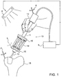
- Fig. 1 illustrates an exemplary hand-held robotic system using the principle described hereinabove.
- the system described herewithin is a surgical system, illustrated here for shaping a bone, but it is to be understood that this is only one exemplary application of such a system and it can equally well be used for other applications where a hand guided operation is to be controlled to ensure that the operator does not deviate from predetermined bounds. Another such example is shown hereinbelow.
- the robotic system includes a hand held robotic operating head 10, which is constructed of two parts.
- An upper part 11 is in the form of a gripping handle which is shaped so that it can be comfortably held in the hand 12 of the surgeon performing the operation.
- the surgeon uses a preoperative plan to decide in which pose (spatial position and angular orientation) to hold the head and which path to follow.
- the operating tool whether a drill, a milling head, or any other surgical tool would be connected directly to the gripping handle
- the tool 13 is connected to the gripping handle, and hence to the surgeon's hand, only through a controlled robot 14.
- the base 15 of the robot is attached to the gripping handle 11, while the operating tool 13 is held in the robotically controlled platform 16 of the robot.
- the robot can be of any type, and is illustrated in this disclosure as a Stewart-Gough parallel robot type, which has 6-extendible operating links between the base and the moveable platform.
- a Stewart-Gough parallel robot type which has 6-extendible operating links between the base and the moveable platform.
- Such a robot is used to illustrate the implementation shown in the drawings and it clearly shows the operating action of the robot to correct the surgeon's deviation from the allowed path.
- the robotic structure used can be of any suitable type, and in particular, a robot with actuating motors incorporated within the handle above the output platform may provide a more compact configuration. Compact dimensions are an important characteristic for such a hand-held application.
- the operating head 10 is shown being used by the surgeon in a unicodyler knee replacement procedure, to mill the surface of a bone 18 with the operating tool 13, so that the milled bone head matches a preselected unicompartmental implant.
- the surgeon has planned the optimal location of the implant, and from this plan, the milled shape of the knee surface is calculated.
- This shape is input to the controller 8 as the preoperative plan which the surgeon has to adhere to accurately in order to ensure compliance with the planned operation, and hence a good fit of the implant on the bone.
- a tracking system is used intra-operatively, to enable dynamic referencing of the bone 18 on which the operation is being performed with the robotic operating head 10. This is performed in order to link the locations of the bone and the robotic operating head 10 to the same coordinate system, so that movements of the robotic operating head can be correlated with the position of the bone.
- the tracking system may utilize a tracker 6 surveilling the operating site, and determining the pose of the robotic operating head 10 and of the subject's bone 18 by means of referencing targets 2, 4, attached to these items. If an optical tracking system is used, the referencing targets may conveniently be constructed of a plurality of light emitting diodes (LEDs) arranged in a predetermined pattern.
- LEDs light emitting diodes
- the tracker 6 may then include optical sensors which are able to determine the pose of the referencing targets, such as by means of triangulation.
- Alternative configurations may include the use of retro-reflectors in the referencing targets 2, 4, in which case the tracker 6 would include both the light emitting sources (usually LED's) and the detectors for receiving the light retro-reflected from the referencing targets.
- trackers are now available which operate in a completely passive mode, requiring no light emitting sources, and relying solely on high reflection coatings on the referencing targets, to reflect the ambient light to the tracker detector 6.
- the tracking system transfers the positional data relating to the robotic operating head and to the bone to the system controller 8, which also contains the preoperative plan data.
- the robot 14 remains locked and the entire robotic operating head 10 is manipulated as one rigid body. Once the surgeon deviates from the allowed path or pose, this deviation is detected by the tracked position of the referencing target 4 on the robotic operating head 10, and the controller is programmed to send a correction signal to the robot 14 to alter its pose, such that the tool tip 13 is brought back into the allowed region, even though the surgeon's hand has directed the robotic operating head 10 beyond those limits.
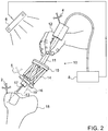
- FIG. 2 This situation is shown in Fig. 2 , where it is seen that the surgeon's hand 12 has deviated, as shown by the axis 19 of the hand grip, from the angle which would maintain the axis 17 of the cutting tool 1 3 in the correct position and pose relative to the bone 18.
- this deviation has been sensed by the navigation 6 and control system 8, and the pose of the robot 14 has been changed in order to maintain the cutting tool 13 in the correct position and pose relative to the bone 18, despite the surgeon's hand deviation.
- the robot 14 thus compensates for the surgeon's deviation and provides accurate compliance with the preoperative plan.
- the robot In order to accomplish this successfully, the robot must react in real-time, which means that the system should have a response time sufficiently short that even with the most rapid movement the surgeon may make, the system will correct departure from the allowed preoperative plan before any damage is done. Typically, this means that the system should have a response bandwidth of the order of at least 10 Hz in order to follow the fastest human hand movements expected in such operations. Furthermore, the surgeon should not make movements much further from the allowed region that would cause the robot to exceed its working envelope. In general, both of these limitations should be achievable with the available robotic actuating motors and robotic control systems.
- the robotic actuators used can be of any type that can supply the required forces and the required speed, such that not only suitable electro-magnetic motors but also piezoelectric, hydraulic or pneumatic actuators may be used.
- warning signal may be incorporated in the system, to advise the surgeon when his hand motion approaches the borders of the allowed region of operation according to the preoperative plan.
- a warning signal may be generated by the robot control, and could also be graduated, such as in intensity, tone or frequency, to indicate the extent of deviation of the surgeon from the preoperative plan.
- Possible implementations of this warning signal could be by an audible signal, or by a visual signal, or by some form of tactic feedback provided by the robot to the surgeon's hand.
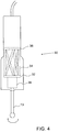
- Fig. 3 shows an additional exemplary application of the hand-held robot of Fig. 1 , for performing a targeted procedure in a region 20 of soft tissue of a subject close to a sensitive anatomical structure, such as a nerve or a critical blood vessel 25.
- a sensitive anatomical structure such as a nerve or a critical blood vessel 25.
- Contact with the sensitive anatomical structure could be damaging to the subject. Examples of such a procedure could be in tumor removal, biopsy performance, precise drug delivery, and others.
- the surgeon or physician can be warned of the presence of the hazardous feature either by an imaging system, such as a fluoroscopic system or by an ultrasonic imaging system, a probe of which 24 is shown in Fig.
- a proximity sensor 29 attached to the needle 22 or surgical tool, which provides a warning signal when the sensor approaches the hazardous feature by a predetermined distance.
- Techniques such as Doppler ultrasound flow detection can be used to detect blood vessels by the flow of blood therein, and neuro-monitors can be used to detect the presence and position of nerve structures.
- the proximity sensor can advantageously deliver its warning signal by radio transmission to the control unit 8. Even for open surgical procedures, where the surgeon or physician could see the damage-sensitive feature, the robotically controlled system of this disclosure enables him to perform the desired procedure close to the damage-sensitive feature without fear that he will cause damage to the feature by a careless and unintentional movement of the hand.
- Either the imaging system or the proximity sensor provides a signal input to the control system 8, which then provides a feedback to the robot 10 to prevent the needle 22 or surgical tool from approaching the sensitive feature, even if the surgeon or physician's hand movement would have directed it to do so.
- Fig. 3 where, although the axis 26 of the handle would have directed the needle 22 straight at the blood vessel 25, the robotic control has changed the pose of the robot so as to divert the needle away from the blood vessel 25 and back to its intended target 20.
- This implementation differs from that shown in Fig. 2 , in that the control system does not limit the operating head to operation within a predefined envelope, but rather prevents the operating head from getting too close to a forbidden region of operation.
- both implementations share the common feature that the robotic control uses a warning signal provided by a position detection system in order to prevent the operating head from operating in a region where the operator's hand movement would have directed it to do so.
- this robotic compensation system has the advantage over prior art free-hand manual proximity warning systems in that the accuracy of the procedure can be increased compared to that of prior art systems having no active control of the surgeon's hand position. It is possible to provide greater precision and thus to operate closer to hazardous locations than using manual proximity warning systems, and thus to achieve a better operational result.
- FIG. 4 shows a schematic cut-away representation of a complete robotic operating head 30 with a robot of sufficiently compact design that it can be incorporated into the body profile of the head.
- the head thus becomes much more compact and readily handled by the surgeon than that shown schematically in Figs 1 to 3 .
- a schematic outline of a robot is shown in dotted lines within the body of the head.
- the surgical tool 13, shown in the example of Fig. 4 with a milling bur on its working extremity may be rotated by means of a motor 38 mounted on the moving platform 32 of the robot, or by a shaft driven by a motor located remotely.
- the moving platform 32 may be actuated by means of robotically actuating arms 34 which are affixed at the end remote from the driven platform to the robotic base, 36, which is fixed relative to the complete robotic operating head 30.
- robotically actuating arms 34 which are affixed at the end remote from the driven platform to the robotic base, 36, which is fixed relative to the complete robotic operating head 30.
- any other suitable robot structure may equally well be used, with its base attached to the robotic operating head 30 and with its driven output element bearing the surgical tool.
- a tracking target 5 can be mounted on the robotic moving platform 16 of the robot 14, such that the actual position of the surgical tool 13 is tracked directly. Since the system controller 8 knows the pose of the robot 14 and hence the positional relation between the gripping portion 11 of the robotic operating head and the surgical tool 13, the use of both of these tracking targets 4, 5, provides a level of redundancy which may be used for increasing the safety of the system.
- the tracking could advantageously be performed locally, such as by mounting the tracker on the bone 18 and the tracking target or targets on the robotic operating head, either on the gripper part 11 or on the robotically directed tool holder platform 16, or on both, or vice versa with the tracker on the robotic operating head (whether the gripper part 11 or the moveable platform 16, or on both) and a tracking target on the bone 18.
Landscapes
- Engineering & Computer Science (AREA)
- Health & Medical Sciences (AREA)
- Surgery (AREA)
- Life Sciences & Earth Sciences (AREA)
- Robotics (AREA)
- Heart & Thoracic Surgery (AREA)
- General Health & Medical Sciences (AREA)
- Biomedical Technology (AREA)
- Mechanical Engineering (AREA)
- Medical Informatics (AREA)
- Molecular Biology (AREA)
- Animal Behavior & Ethology (AREA)
- Nuclear Medicine, Radiotherapy & Molecular Imaging (AREA)
- Public Health (AREA)
- Veterinary Medicine (AREA)
- Dentistry (AREA)
- Oral & Maxillofacial Surgery (AREA)
- Orthopedic Medicine & Surgery (AREA)
- Manipulator (AREA)
Claims (15)
- Système robotique comprenant :
une tête d'opération robotique à main (10) comprenant :un corps de préhension (11) adapté pour être tenu par l'opérateur (12) ; etun robot (14) ayant une base (15) et une plateforme à commande robotique (16), ladite base étant fixée audit corps de préhension (11) et ladite plateforme à commande robotique étant conçue pour porter un outil d'opération (13) ;dans lequel ladite tête d'opération robotique est telle que ledit opérateur peut manipuler librement la tête d'opération robotique entière ; etun système de détection (6) adapté pour faire part de la position dudit outil d'opération par rapport à un objet (18) sur lequel opère ledit outil d'opération, ledit robot étant adapté pour utiliser une donnée dudit système de détection afin de changer la pose de ladite plateforme à commande robotique si ledit corps de préhension dévie d'un degré qui ferait opérer ledit outil d'opération dans une région dudit objet où il est interdit audit outil d'opération d'opérer, caractérisé en ce que ledit système robotique est configuré de manière autonome pour être inopérant de telle sorte que ladite tête d'opération robotique à main soit rigide lorsque ladite donnée indique que ledit outil d'opération opère à l'extérieur de ladite région où il est interdit audit outil d'opération d'opérer et en ce que ladite tête d'opération robotique à main est configurée pour être activement commandée par ledit système robotique une fois que ladite donnée indique que ledit outil d'opération a atteint ladite région où il est interdit audit outil d'opération d'opérer. - Système robotique selon la revendication 1, dans lequel ladite région où il est interdit audit outil d'opération d'opérer est une région dans laquelle ledit outil d'opération dévie de plus d'un degré prédéfini à partir d'une trajectoire d'opération préétablie.
- Système robotique selon la revendication 1, dans lequel ladite région où il est interdit audit outil d'opération d'opérer est une région qui dévie de plus qu'un degré prédéfini d'un plan chirurgical destiné à être exécuté sur un sujet.
- Système robotique selon l'une des revendications 2 ou 3, dans lequel ledit outil d'opération est un outil chirurgical destiné à effectuer une opération orthopédique sur un os du sujet.
- Système robotique selon l'une quelconque des revendications précédentes, dans lequel ledit système de détection comprend un système de suivi qui détecte la pose dudit corps de préhension, de ladite plateforme à commande robotique, dudit outil d'opération et/ou dudit objet.
- Système robotique selon la revendication 1, dans lequel ladite région où il est interdit audit outil d'opération d'opérer est une région qui est plus proche de plus d'une distance prédéfinie d'une caractéristique susceptible d'être endommagée par ledit outil d'opération.
- Système robotique selon la revendication 1, dans lequel ladite région où il est interdit audit outil d'opération d'opérer est une région qui dévie de plus qu'un degré prédéfini d'un plan chirurgical destiné à être exécuté sur un sujet.
- Système robotique selon la revendication 6, dans lequel ledit outil d'opération est un outil chirurgical destiné à effectuer une intervention chirurgicale dans des tissus mous (20) à proximité d'une région sensible aux dommages d'un sujet.
- Système robotique selon la revendication 8, dans lequel ledit outil chirurgical est l'un quelconque d'une aiguille de biopsie (22), d'une aiguille d'administration de médicament (22) et d'un scalpel.
- Système robotique selon l'une quelconque des revendications 8 et 9, dans lequel ladite procédure chirurgicale est l'une quelconque de l'ablation de tumeur, de la réalisation de biopsie et de l'administration de médicament.
- Système robotique selon la revendication 8, dans lequel ladite région sensible aux dommages comprend l'un quelconque d'un nerf, d'un vaisseau sanguin (25), d'un organe corporel et d'une région sensible du cerveau.
- Système robotique selon l'une quelconque des revendications 8 à 11, dans lequel ledit système de détection comprend un capteur de proximité (29) permettant de déterminer la distance dudit outil d'opération à ladite région sensible aux dommages et dans lequel ledit robot est en outre adapté pour utiliser une sortie dudit capteur de proximité afin de changer la pose de ladite plateforme à commande robotique si ledit corps de préhension s'approche de ladite région sensible aux dommages d'un degré prédéfini.
- Système robotique selon la revendication 12, dans lequel ledit capteur de proximité comprend soit un débitmètre sanguin à ultrason à effet Doppler, soit un moniteur neuronal.
- Système robotique selon l'une quelconque des revendications précédentes, dans lequel ledit système de détection comprend un système de suivi ayant soit :(a) une tête de suivi montée sur ledit objet (18) soit une cible de suivi (4), (5) montée sur ledit corps de préhension et/ou sur ladite plateforme à commande robotique, ou(b) une tête de suivi, montée sur ledit corps de préhension et/ou sur ladite plateforme à commande robotique, et une cible de suivi (4), (5), montée sur ledit objet (18).
- Système robotique selon l'une quelconque des revendications précédentes, dans lequel ledit système robotique est configuré pour générer un signal d'avertissement gradué indiquant l'étendue de la déviation dudit opérateur par rapport à un plan préopératoire.
Applications Claiming Priority (2)
| Application Number | Priority Date | Filing Date | Title |
|---|---|---|---|
| US27210909P | 2009-08-17 | 2009-08-17 | |
| PCT/IL2010/000667 WO2011021192A1 (fr) | 2009-08-17 | 2010-08-17 | Dispositif permettant d'améliorer la précision d'opérations manuelles |
Publications (3)
| Publication Number | Publication Date |
|---|---|
| EP2467798A1 EP2467798A1 (fr) | 2012-06-27 |
| EP2467798A4 EP2467798A4 (fr) | 2016-10-05 |
| EP2467798B1 true EP2467798B1 (fr) | 2020-04-15 |
Family
ID=43606695
Family Applications (1)
| Application Number | Title | Priority Date | Filing Date |
|---|---|---|---|
| EP10809631.4A Active EP2467798B1 (fr) | 2009-08-17 | 2010-08-17 | Dispositif permettant d'améliorer la précision d'opérations manuelles |
Country Status (4)
| Country | Link |
|---|---|
| US (2) | US10828786B2 (fr) |
| EP (1) | EP2467798B1 (fr) |
| CA (1) | CA2770507C (fr) |
| WO (1) | WO2011021192A1 (fr) |
Families Citing this family (179)
| Publication number | Priority date | Publication date | Assignee | Title |
|---|---|---|---|---|
| US8010180B2 (en) | 2002-03-06 | 2011-08-30 | Mako Surgical Corp. | Haptic guidance system and method |
| DE10239673A1 (de) * | 2002-08-26 | 2004-03-11 | Markus Schwarz | Vorrichtung zur Bearbeitung von Teilen |
| US10653497B2 (en) | 2006-02-16 | 2020-05-19 | Globus Medical, Inc. | Surgical tool systems and methods |
| US10893912B2 (en) | 2006-02-16 | 2021-01-19 | Globus Medical Inc. | Surgical tool systems and methods |
| US10357184B2 (en) | 2012-06-21 | 2019-07-23 | Globus Medical, Inc. | Surgical tool systems and method |
| US8588892B2 (en) | 2008-12-02 | 2013-11-19 | Avenir Medical Inc. | Method and system for aligning a prosthesis during surgery using active sensors |
| WO2011021192A1 (fr) * | 2009-08-17 | 2011-02-24 | Mazor Surgical Technologies Ltd. | Dispositif permettant d'améliorer la précision d'opérations manuelles |
| AU2011342900A1 (en) | 2010-12-17 | 2013-07-18 | Intellijoint Surgical Inc. | Method and system for aligning a prosthesis during surgery |
| US9921712B2 (en) | 2010-12-29 | 2018-03-20 | Mako Surgical Corp. | System and method for providing substantially stable control of a surgical tool |
| US9119655B2 (en) | 2012-08-03 | 2015-09-01 | Stryker Corporation | Surgical manipulator capable of controlling a surgical instrument in multiple modes |
| US9308050B2 (en) | 2011-04-01 | 2016-04-12 | Ecole Polytechnique Federale De Lausanne (Epfl) | Robotic system and method for spinal and other surgeries |
| US9026242B2 (en) * | 2011-05-19 | 2015-05-05 | Taktia Llc | Automatically guided tools |
| CA3067299A1 (fr) | 2011-09-02 | 2013-03-07 | Stryker Corporation | Instrument chirurgical comprenant un boitier, un accessoire de coupe qui s'etend a partir du boitier et des actionneurs qui etablissent la position de l'accessoire de coupe par rapport au boitier |
| US9060794B2 (en) * | 2011-10-18 | 2015-06-23 | Mako Surgical Corp. | System and method for robotic surgery |
| JP6366506B2 (ja) | 2011-11-04 | 2018-08-01 | ザ・ジョンズ・ホプキンス・ユニバーシティ | 安定性を有する顕微手術ロボットおよびロボットシステム |
| US9314188B2 (en) | 2012-04-12 | 2016-04-19 | Intellijoint Surgical Inc. | Computer-assisted joint replacement surgery and navigation systems |
| US11317971B2 (en) | 2012-06-21 | 2022-05-03 | Globus Medical, Inc. | Systems and methods related to robotic guidance in surgery |
| US10624710B2 (en) | 2012-06-21 | 2020-04-21 | Globus Medical, Inc. | System and method for measuring depth of instrumentation |
| US11864839B2 (en) | 2012-06-21 | 2024-01-09 | Globus Medical Inc. | Methods of adjusting a virtual implant and related surgical navigation systems |
| US11864745B2 (en) | 2012-06-21 | 2024-01-09 | Globus Medical, Inc. | Surgical robotic system with retractor |
| US11399900B2 (en) | 2012-06-21 | 2022-08-02 | Globus Medical, Inc. | Robotic systems providing co-registration using natural fiducials and related methods |
| US10842461B2 (en) | 2012-06-21 | 2020-11-24 | Globus Medical, Inc. | Systems and methods of checking registrations for surgical systems |
| US11298196B2 (en) | 2012-06-21 | 2022-04-12 | Globus Medical Inc. | Surgical robotic automation with tracking markers and controlled tool advancement |
| US11253327B2 (en) | 2012-06-21 | 2022-02-22 | Globus Medical, Inc. | Systems and methods for automatically changing an end-effector on a surgical robot |
| US11395706B2 (en) | 2012-06-21 | 2022-07-26 | Globus Medical Inc. | Surgical robot platform |
| JP2015528713A (ja) | 2012-06-21 | 2015-10-01 | グローバス メディカル インコーポレイティッド | 手術ロボットプラットフォーム |
| US11589771B2 (en) | 2012-06-21 | 2023-02-28 | Globus Medical Inc. | Method for recording probe movement and determining an extent of matter removed |
| US10136954B2 (en) | 2012-06-21 | 2018-11-27 | Globus Medical, Inc. | Surgical tool systems and method |
| US10231791B2 (en) | 2012-06-21 | 2019-03-19 | Globus Medical, Inc. | Infrared signal based position recognition system for use with a robot-assisted surgery |
| US10874466B2 (en) | 2012-06-21 | 2020-12-29 | Globus Medical, Inc. | System and method for surgical tool insertion using multiaxis force and moment feedback |
| US11974822B2 (en) | 2012-06-21 | 2024-05-07 | Globus Medical Inc. | Method for a surveillance marker in robotic-assisted surgery |
| US11857266B2 (en) | 2012-06-21 | 2024-01-02 | Globus Medical, Inc. | System for a surveillance marker in robotic-assisted surgery |
| US11896446B2 (en) | 2012-06-21 | 2024-02-13 | Globus Medical, Inc | Surgical robotic automation with tracking markers |
| US10646280B2 (en) | 2012-06-21 | 2020-05-12 | Globus Medical, Inc. | System and method for surgical tool insertion using multiaxis force and moment feedback |
| US10758315B2 (en) | 2012-06-21 | 2020-09-01 | Globus Medical Inc. | Method and system for improving 2D-3D registration convergence |
| US10350013B2 (en) | 2012-06-21 | 2019-07-16 | Globus Medical, Inc. | Surgical tool systems and methods |
| US11607149B2 (en) | 2012-06-21 | 2023-03-21 | Globus Medical Inc. | Surgical tool systems and method |
| US11116576B2 (en) | 2012-06-21 | 2021-09-14 | Globus Medical Inc. | Dynamic reference arrays and methods of use |
| US11793570B2 (en) | 2012-06-21 | 2023-10-24 | Globus Medical Inc. | Surgical robotic automation with tracking markers |
| US10799298B2 (en) | 2012-06-21 | 2020-10-13 | Globus Medical Inc. | Robotic fluoroscopic navigation |
| US11963755B2 (en) | 2012-06-21 | 2024-04-23 | Globus Medical Inc. | Apparatus for recording probe movement |
| US11045267B2 (en) | 2012-06-21 | 2021-06-29 | Globus Medical, Inc. | Surgical robotic automation with tracking markers |
| US11857149B2 (en) | 2012-06-21 | 2024-01-02 | Globus Medical, Inc. | Surgical robotic systems with target trajectory deviation monitoring and related methods |
| US11786324B2 (en) | 2012-06-21 | 2023-10-17 | Globus Medical, Inc. | Surgical robotic automation with tracking markers |
| US9820818B2 (en) | 2012-08-03 | 2017-11-21 | Stryker Corporation | System and method for controlling a surgical manipulator based on implant parameters |
| CA2879414A1 (fr) | 2012-08-03 | 2014-02-06 | Stryker Corporation | Systemes et procedes pour chirurgie robotique |
| US9226796B2 (en) | 2012-08-03 | 2016-01-05 | Stryker Corporation | Method for detecting a disturbance as an energy applicator of a surgical instrument traverses a cutting path |
| DE202013012276U1 (de) * | 2012-09-30 | 2016-01-20 | M.S.T. Medical Surgery Technologies Ltd. | Vorrichtung zum unterstützen eines laparoskopischeneingriffs - lenk- und manövriergelenkwerkzeug |
| US9652591B2 (en) | 2013-03-13 | 2017-05-16 | Stryker Corporation | System and method for arranging objects in an operating room in preparation for surgical procedures |
| AU2014248758B2 (en) | 2013-03-13 | 2018-04-12 | Stryker Corporation | System for establishing virtual constraint boundaries |
| US9247998B2 (en) | 2013-03-15 | 2016-02-02 | Intellijoint Surgical Inc. | System and method for intra-operative leg position measurement |
| CN105431102B (zh) * | 2013-06-11 | 2018-01-30 | 迷你麦克斯医疗 | 用于身体部分的计划量的处理的系统 |
| FR3010628B1 (fr) | 2013-09-18 | 2015-10-16 | Medicrea International | Procede permettant de realiser la courbure ideale d'une tige d'un materiel d'osteosynthese vertebrale destinee a etayer la colonne vertebrale d'un patient |
| US9283048B2 (en) | 2013-10-04 | 2016-03-15 | KB Medical SA | Apparatus and systems for precise guidance of surgical tools |
| FR3012030B1 (fr) | 2013-10-18 | 2015-12-25 | Medicrea International | Procede permettant de realiser la courbure ideale d'une tige d'un materiel d'osteosynthese vertebrale destinee a etayer la colonne vertebrale d'un patient |
| TWI548388B (zh) | 2013-12-30 | 2016-09-11 | 國立臺灣大學 | 骨科手術之手持式機器人以及其控制方法 |
| WO2015107099A1 (fr) | 2014-01-15 | 2015-07-23 | KB Medical SA | Appareil entaillé pour guider un instrument pouvant être introduit le long d'un axe pendant une chirurgie rachidienne |
| WO2015121311A1 (fr) | 2014-02-11 | 2015-08-20 | KB Medical SA | Poignée stérile de commande d'un système chirurgical robotique à partir d'un champ stérile |
| US10004562B2 (en) | 2014-04-24 | 2018-06-26 | Globus Medical, Inc. | Surgical instrument holder for use with a robotic surgical system |
| EP3136973B1 (fr) | 2014-04-28 | 2019-08-14 | Mazor Robotics Ltd. | Robot tenu à la main et guidé par ultrasons |
| US10828120B2 (en) | 2014-06-19 | 2020-11-10 | Kb Medical, Sa | Systems and methods for performing minimally invasive surgery |
| US10765438B2 (en) * | 2014-07-14 | 2020-09-08 | KB Medical SA | Anti-skid surgical instrument for use in preparing holes in bone tissue |
| WO2016008880A1 (fr) | 2014-07-14 | 2016-01-21 | KB Medical SA | Instrument chirurgical anti-dérapage destiné à être utilisé pour préparer des trous dans un tissu osseux |
| KR102511541B1 (ko) * | 2014-09-23 | 2023-03-16 | 씽크 써지컬, 인크. | 다평면의 가변형상 지그재그 절단 접이식 드릴 시스템 |
| JP6731920B2 (ja) | 2014-12-02 | 2020-07-29 | カーベー メディカル エスアー | 外科手術中のロボット支援式体積除去 |
| US10013808B2 (en) | 2015-02-03 | 2018-07-03 | Globus Medical, Inc. | Surgeon head-mounted display apparatuses |
| EP3258872B1 (fr) | 2015-02-18 | 2023-04-26 | KB Medical SA | Systèmes pour pratiquer des micromanipulations chirurgicales à la colonne vertébrale avec un système chirurgical robotique en utilisant une technique percutanée |
| US10646298B2 (en) | 2015-07-31 | 2020-05-12 | Globus Medical, Inc. | Robot arm and methods of use |
| US10058394B2 (en) | 2015-07-31 | 2018-08-28 | Globus Medical, Inc. | Robot arm and methods of use |
| US10080615B2 (en) | 2015-08-12 | 2018-09-25 | Globus Medical, Inc. | Devices and methods for temporary mounting of parts to bone |
| US10687905B2 (en) | 2015-08-31 | 2020-06-23 | KB Medical SA | Robotic surgical systems and methods |
| US10034716B2 (en) | 2015-09-14 | 2018-07-31 | Globus Medical, Inc. | Surgical robotic systems and methods thereof |
| US9771092B2 (en) | 2015-10-13 | 2017-09-26 | Globus Medical, Inc. | Stabilizer wheel assembly and methods of use |
| US10058393B2 (en) | 2015-10-21 | 2018-08-28 | P Tech, Llc | Systems and methods for navigation and visualization |
| WO2017079655A2 (fr) | 2015-11-04 | 2017-05-11 | Mcafee Paul C | Procédés et appareil pour chirurgie de reconstruction spinale et mesure de la longueur spinale et de l'espacement intervertébral, de la tension et de la rotation |
| CN108348294A (zh) | 2015-11-24 | 2018-07-31 | 思想外科有限公司 | 用于全膝关节置换术中的主动式机器人钉配置 |
| US10568640B2 (en) | 2015-11-30 | 2020-02-25 | Stryker Corporation | Surgical instrument with telescoping nose mechanism |
| US10285715B2 (en) * | 2015-12-21 | 2019-05-14 | Warsaw Orthopedic, Inc. | Surgical instrument and method |
| WO2017117369A1 (fr) | 2015-12-31 | 2017-07-06 | Stryker Corporation | Système et procédés pour réaliser une intervention chirurgicale sur un patient au niveau d'un site cible défini par un objet virtuel |
| WO2017130060A1 (fr) | 2016-01-26 | 2017-08-03 | Ciriello Christopher John | Système de traitement dentaire automatisé |
| US10448910B2 (en) | 2016-02-03 | 2019-10-22 | Globus Medical, Inc. | Portable medical imaging system |
| US11058378B2 (en) | 2016-02-03 | 2021-07-13 | Globus Medical, Inc. | Portable medical imaging system |
| US10842453B2 (en) | 2016-02-03 | 2020-11-24 | Globus Medical, Inc. | Portable medical imaging system |
| US10117632B2 (en) | 2016-02-03 | 2018-11-06 | Globus Medical, Inc. | Portable medical imaging system with beam scanning collimator |
| US11883217B2 (en) | 2016-02-03 | 2024-01-30 | Globus Medical, Inc. | Portable medical imaging system and method |
| US10866119B2 (en) | 2016-03-14 | 2020-12-15 | Globus Medical, Inc. | Metal detector for detecting insertion of a surgical device into a hollow tube |
| JP2017176307A (ja) * | 2016-03-29 | 2017-10-05 | ソニー株式会社 | 医療用支持アームの制御装置、医療用支持アーム装置の制御方法及び医療用システム |
| EP3241518A3 (fr) | 2016-04-11 | 2018-01-24 | Globus Medical, Inc | Procédés et systèmes d'outil chirurgical |
| EP3451946A1 (fr) * | 2016-05-03 | 2019-03-13 | Bien-Air Holding SA | Système de surveillance préopératoire des nerfs intégrée |
| GB201615438D0 (en) * | 2016-09-12 | 2016-10-26 | Imp Innovations Ltd | Apparatus and method for assisting tool use |
| US11039893B2 (en) | 2016-10-21 | 2021-06-22 | Globus Medical, Inc. | Robotic surgical systems |
| US11974761B2 (en) * | 2016-12-08 | 2024-05-07 | Orthotaxy S.A.S. | Surgical system for cutting an anatomical structure according to at least one target plane |
| US11607229B2 (en) * | 2016-12-08 | 2023-03-21 | Orthotaxy S.A.S. | Surgical system for cutting an anatomical structure according to at least one target plane |
| WO2018109556A1 (fr) | 2016-12-12 | 2018-06-21 | Medicrea International | Systèmes et procédés pour des implants rachidiens spécifiques au patient |
| WO2018112025A1 (fr) * | 2016-12-16 | 2018-06-21 | Mako Surgical Corp. | Techniques pour modifier le fonctionnement d'un outil dans un système robotisé chirurgical sur la base de la comparaison des états réels et commandés de l'outil par rapport à un site chirurgical |
| WO2018132835A1 (fr) * | 2017-01-16 | 2018-07-19 | Smith & Nephew, Inc. | Outil chirurgical suivi à extension régulée |
| EP3351202B1 (fr) | 2017-01-18 | 2021-09-08 | KB Medical SA | Guide d'instrument universel destiné à des systèmes chirurgicaux robotiques |
| EP3360502A3 (fr) | 2017-01-18 | 2018-10-31 | KB Medical SA | Navigation robotique de systèmes chirurgicaux robotiques |
| JP2018114280A (ja) | 2017-01-18 | 2018-07-26 | ケービー メディカル エスアー | ロボット外科用システムのための汎用器具ガイド、外科用器具システム、及びそれらの使用方法 |
| JP7304820B2 (ja) * | 2017-02-14 | 2023-07-07 | アトラクシス エス・アー・エール・エル | 圧縮および/またはcmosウィンドウイングを用いた高速光学追跡 |
| CA3059462A1 (fr) * | 2017-02-22 | 2018-08-30 | Christopher John Ciriello | Systeme de traitement dentaire automatise |
| US11071594B2 (en) | 2017-03-16 | 2021-07-27 | KB Medical SA | Robotic navigation of robotic surgical systems |
| EP3612125A1 (fr) | 2017-04-21 | 2020-02-26 | Medicrea International | Système de suivi intra-opératoire pour assister la chirurgie rachidienne |
| US11135015B2 (en) | 2017-07-21 | 2021-10-05 | Globus Medical, Inc. | Robot surgical platform |
| US11027432B2 (en) | 2017-09-06 | 2021-06-08 | Stryker Corporation | Techniques for controlling position of an end effector of a robotic device relative to a virtual constraint |
| US11382666B2 (en) | 2017-11-09 | 2022-07-12 | Globus Medical Inc. | Methods providing bend plans for surgical rods and related controllers and computer program products |
| US10898252B2 (en) | 2017-11-09 | 2021-01-26 | Globus Medical, Inc. | Surgical robotic systems for bending surgical rods, and related methods and devices |
| US11794338B2 (en) | 2017-11-09 | 2023-10-24 | Globus Medical Inc. | Robotic rod benders and related mechanical and motor housings |
| US11134862B2 (en) | 2017-11-10 | 2021-10-05 | Globus Medical, Inc. | Methods of selecting surgical implants and related devices |
| AU2018368440B2 (en) | 2017-11-16 | 2022-03-03 | Aivita Biomedical, Inc. | Use of cell membrane-bound signaling factors |
| US10918422B2 (en) | 2017-12-01 | 2021-02-16 | Medicrea International | Method and apparatus for inhibiting proximal junctional failure |
| CA3086691A1 (fr) * | 2018-01-22 | 2019-07-25 | Claronav Inc. | Instrument chirurgical robotise |
| US20190254753A1 (en) | 2018-02-19 | 2019-08-22 | Globus Medical, Inc. | Augmented reality navigation systems for use with robotic surgical systems and methods of their use |
| US10573023B2 (en) | 2018-04-09 | 2020-02-25 | Globus Medical, Inc. | Predictive visualization of medical imaging scanner component movement |
| US10888385B2 (en) | 2018-07-09 | 2021-01-12 | Point Robotics Medtech Inc. | Calibration device and calibration method for surgical instrument |
| US11612438B2 (en) | 2018-09-05 | 2023-03-28 | Point Robotics Medtech Inc. | Navigation system and method for medical operation by a robotic system using a tool |
| US11337742B2 (en) | 2018-11-05 | 2022-05-24 | Globus Medical Inc | Compliant orthopedic driver |
| US11278360B2 (en) | 2018-11-16 | 2022-03-22 | Globus Medical, Inc. | End-effectors for surgical robotic systems having sealed optical components |
| US11602402B2 (en) | 2018-12-04 | 2023-03-14 | Globus Medical, Inc. | Drill guide fixtures, cranial insertion fixtures, and related methods and robotic systems |
| US11744655B2 (en) | 2018-12-04 | 2023-09-05 | Globus Medical, Inc. | Drill guide fixtures, cranial insertion fixtures, and related methods and robotic systems |
| US11471169B1 (en) | 2019-01-07 | 2022-10-18 | Smith & Nephew, Inc. | Tracked surgical tool with flexible lumen and exposure control |
| WO2020163587A1 (fr) | 2019-02-06 | 2020-08-13 | The Johns Hopkins University | Imagerie de tomographie par cohérence optique peropératoire externe et interne pour distribution de matériau sous-rétinien |
| US11918313B2 (en) | 2019-03-15 | 2024-03-05 | Globus Medical Inc. | Active end effectors for surgical robots |
| US11419616B2 (en) | 2019-03-22 | 2022-08-23 | Globus Medical, Inc. | System for neuronavigation registration and robotic trajectory guidance, robotic surgery, and related methods and devices |
| US20200297357A1 (en) | 2019-03-22 | 2020-09-24 | Globus Medical, Inc. | System for neuronavigation registration and robotic trajectory guidance, robotic surgery, and related methods and devices |
| US11571265B2 (en) | 2019-03-22 | 2023-02-07 | Globus Medical Inc. | System for neuronavigation registration and robotic trajectory guidance, robotic surgery, and related methods and devices |
| US11806084B2 (en) | 2019-03-22 | 2023-11-07 | Globus Medical, Inc. | System for neuronavigation registration and robotic trajectory guidance, and related methods and devices |
| US11382549B2 (en) | 2019-03-22 | 2022-07-12 | Globus Medical, Inc. | System for neuronavigation registration and robotic trajectory guidance, and related methods and devices |
| US11317978B2 (en) | 2019-03-22 | 2022-05-03 | Globus Medical, Inc. | System for neuronavigation registration and robotic trajectory guidance, robotic surgery, and related methods and devices |
| US11406454B2 (en) | 2019-03-29 | 2022-08-09 | Gyrus Acmi, Inc. | Anti-perforation device |
| US11925417B2 (en) | 2019-04-02 | 2024-03-12 | Medicrea International | Systems, methods, and devices for developing patient-specific spinal implants, treatments, operations, and/or procedures |
| US11877801B2 (en) | 2019-04-02 | 2024-01-23 | Medicrea International | Systems, methods, and devices for developing patient-specific spinal implants, treatments, operations, and/or procedures |
| US11045179B2 (en) | 2019-05-20 | 2021-06-29 | Global Medical Inc | Robot-mounted retractor system |
| US11628023B2 (en) | 2019-07-10 | 2023-04-18 | Globus Medical, Inc. | Robotic navigational system for interbody implants |
| AU2020315615A1 (en) * | 2019-07-15 | 2022-02-17 | Stryker Corporation | Robotic hand-held surgical instrument systems and methods |
| US11571171B2 (en) | 2019-09-24 | 2023-02-07 | Globus Medical, Inc. | Compound curve cable chain |
| US11426178B2 (en) | 2019-09-27 | 2022-08-30 | Globus Medical Inc. | Systems and methods for navigating a pin guide driver |
| US11864857B2 (en) | 2019-09-27 | 2024-01-09 | Globus Medical, Inc. | Surgical robot with passive end effector |
| US11890066B2 (en) | 2019-09-30 | 2024-02-06 | Globus Medical, Inc | Surgical robot with passive end effector |
| US11510684B2 (en) | 2019-10-14 | 2022-11-29 | Globus Medical, Inc. | Rotary motion passive end effector for surgical robots in orthopedic surgeries |
| EP3811892A1 (fr) | 2019-10-24 | 2021-04-28 | Point Robotics Medtech Inc. | Dispositif et procédé d'étalonnage pour instrument chirurgical |
| JP7154606B2 (ja) * | 2019-12-05 | 2022-10-18 | 炳碩生醫股▲フン▼有限公司 | 手術用器具の校正装置及び校正方法 |
| EP4081153A1 (fr) | 2019-12-23 | 2022-11-02 | Mazor Robotics Ltd. | Système robotique à bras multiples pour chirurgie de la colonne vertébrale à guidage d'imagerie |
| US11769251B2 (en) | 2019-12-26 | 2023-09-26 | Medicrea International | Systems and methods for medical image analysis |
| WO2021147268A1 (fr) * | 2020-01-23 | 2021-07-29 | 诺创智能医疗科技(杭州)有限公司 | Bras de robot chirurgical et robot chirurgical |
| CN113561220B (zh) * | 2020-01-23 | 2022-07-01 | 诺创智能医疗科技(杭州)有限公司 | 手术机械臂、计算机设备及计算机可读存储介质 |
| CN111227940B (zh) * | 2020-01-23 | 2021-11-30 | 诺创智能医疗科技(杭州)有限公司 | 手术机械臂及手术机器人 |
| WO2021147270A1 (fr) * | 2020-01-23 | 2021-07-29 | 诺创智能医疗科技(杭州)有限公司 | Bras de robot chirurgical et robot chirurgical |
| US11464581B2 (en) | 2020-01-28 | 2022-10-11 | Globus Medical, Inc. | Pose measurement chaining for extended reality surgical navigation in visible and near infrared spectrums |
| US11382699B2 (en) | 2020-02-10 | 2022-07-12 | Globus Medical Inc. | Extended reality visualization of optical tool tracking volume for computer assisted navigation in surgery |
| US11207150B2 (en) | 2020-02-19 | 2021-12-28 | Globus Medical, Inc. | Displaying a virtual model of a planned instrument attachment to ensure correct selection of physical instrument attachment |
| US11253216B2 (en) | 2020-04-28 | 2022-02-22 | Globus Medical Inc. | Fixtures for fluoroscopic imaging systems and related navigation systems and methods |
| US11510750B2 (en) | 2020-05-08 | 2022-11-29 | Globus Medical, Inc. | Leveraging two-dimensional digital imaging and communication in medicine imagery in three-dimensional extended reality applications |
| US11153555B1 (en) | 2020-05-08 | 2021-10-19 | Globus Medical Inc. | Extended reality headset camera system for computer assisted navigation in surgery |
| US11382700B2 (en) | 2020-05-08 | 2022-07-12 | Globus Medical Inc. | Extended reality headset tool tracking and control |
| KR20230010216A (ko) * | 2020-05-11 | 2023-01-18 | 씽크 써지컬, 인크. | 로봇 절제 동안 측정으로 안내되는 재처리 |
| US11317973B2 (en) | 2020-06-09 | 2022-05-03 | Globus Medical, Inc. | Camera tracking bar for computer assisted navigation during surgery |
| US11382713B2 (en) | 2020-06-16 | 2022-07-12 | Globus Medical, Inc. | Navigated surgical system with eye to XR headset display calibration |
| US11877807B2 (en) | 2020-07-10 | 2024-01-23 | Globus Medical, Inc | Instruments for navigated orthopedic surgeries |
| US11793588B2 (en) | 2020-07-23 | 2023-10-24 | Globus Medical, Inc. | Sterile draping of robotic arms |
| US11737831B2 (en) | 2020-09-02 | 2023-08-29 | Globus Medical Inc. | Surgical object tracking template generation for computer assisted navigation during surgical procedure |
| US11523785B2 (en) | 2020-09-24 | 2022-12-13 | Globus Medical, Inc. | Increased cone beam computed tomography volume length without requiring stitching or longitudinal C-arm movement |
| US11911112B2 (en) | 2020-10-27 | 2024-02-27 | Globus Medical, Inc. | Robotic navigational system |
| US11941814B2 (en) | 2020-11-04 | 2024-03-26 | Globus Medical Inc. | Auto segmentation using 2-D images taken during 3-D imaging spin |
| US20240008910A1 (en) * | 2020-11-06 | 2024-01-11 | Stryker Corporation | Robotic Hand-Held Surgical Instrument Systems And Methods |
| US11717350B2 (en) | 2020-11-24 | 2023-08-08 | Globus Medical Inc. | Methods for robotic assistance and navigation in spinal surgery and related systems |
| EP4011312B1 (fr) * | 2020-12-10 | 2023-08-23 | DePuy Ireland Unlimited Company | Système chirurgical robotique |
| US11696809B2 (en) * | 2020-12-30 | 2023-07-11 | Point Robotics (Singapore) Pte. Ltd. | Medical device for manipulating surgical tools |
| CN113017834B (zh) * | 2021-02-26 | 2023-07-18 | 杭州柳叶刀机器人有限公司 | 一种关节置换手术导航装置及方法 |
| AU2022247392A1 (en) | 2021-03-31 | 2023-09-28 | Moon Surgical Sas | Co-manipulation surgical system for use with surgical instruments for performing laparoscopic surgery |
| US11844583B2 (en) | 2021-03-31 | 2023-12-19 | Moon Surgical Sas | Co-manipulation surgical system having an instrument centering mode for automatic scope movements |
| US11832909B2 (en) | 2021-03-31 | 2023-12-05 | Moon Surgical Sas | Co-manipulation surgical system having actuatable setup joints |
| US11819302B2 (en) | 2021-03-31 | 2023-11-21 | Moon Surgical Sas | Co-manipulation surgical system having user guided stage control |
| US11812938B2 (en) | 2021-03-31 | 2023-11-14 | Moon Surgical Sas | Co-manipulation surgical system having a coupling mechanism removeably attachable to surgical instruments |
| US11857273B2 (en) | 2021-07-06 | 2024-01-02 | Globus Medical, Inc. | Ultrasonic robotic surgical navigation |
| US11439444B1 (en) | 2021-07-22 | 2022-09-13 | Globus Medical, Inc. | Screw tower and rod reduction tool |
| US11918304B2 (en) | 2021-12-20 | 2024-03-05 | Globus Medical, Inc | Flat panel registration fixture and method of using same |
| US11839442B1 (en) | 2023-01-09 | 2023-12-12 | Moon Surgical Sas | Co-manipulation surgical system for use with surgical instruments for performing laparoscopic surgery while estimating hold force |
| CN117301044A (zh) * | 2023-08-31 | 2023-12-29 | 北京纳通医用机器人科技有限公司 | 末端工具的运动控制方法、装置、设备及存储介质 |
Citations (1)
| Publication number | Priority date | Publication date | Assignee | Title |
|---|---|---|---|---|
| US20060142657A1 (en) * | 2002-03-06 | 2006-06-29 | Mako Surgical Corporation | Haptic guidance system and method |
Family Cites Families (10)
| Publication number | Priority date | Publication date | Assignee | Title |
|---|---|---|---|---|
| US6535794B1 (en) | 1993-02-23 | 2003-03-18 | Faro Technologoies Inc. | Method of generating an error map for calibration of a robot or multi-axis machining center |
| DE19700402C2 (de) | 1997-01-08 | 1999-12-30 | Ferdinand Peer | Instrument zur Kompensation des Handzitterns bei der Manipulation feiner Strukturen |
| US6810281B2 (en) | 2000-12-21 | 2004-10-26 | Endovia Medical, Inc. | Medical mapping system |
| WO2002060653A2 (fr) * | 2001-01-29 | 2002-08-08 | The Acrobot Company Limited | Robots a action limitee |
| JP4295086B2 (ja) | 2001-07-11 | 2009-07-15 | ヌバシブ, インコーポレイテッド | 手術の間の神経近接度、神経の方向、および病理学を決定するシステムおよび方法 |
| DE10239673A1 (de) * | 2002-08-26 | 2004-03-11 | Markus Schwarz | Vorrichtung zur Bearbeitung von Teilen |
| US7204835B2 (en) | 2004-02-02 | 2007-04-17 | Gyrus Medical, Inc. | Surgical instrument |
| JP2010514512A (ja) * | 2006-12-27 | 2010-05-06 | マコ サージカル コーポレーション | 空間内に調節可能なポジティブストップを設ける装置および方法 |
| US20080228072A1 (en) * | 2007-03-16 | 2008-09-18 | Warsaw Orthopedic, Inc. | Foreign Body Identifier |
| WO2011021192A1 (fr) | 2009-08-17 | 2011-02-24 | Mazor Surgical Technologies Ltd. | Dispositif permettant d'améliorer la précision d'opérations manuelles |
-
2010
- 2010-08-17 WO PCT/IL2010/000667 patent/WO2011021192A1/fr active Application Filing
- 2010-08-17 EP EP10809631.4A patent/EP2467798B1/fr active Active
- 2010-08-17 US US13/390,500 patent/US10828786B2/en active Active
- 2010-08-17 CA CA2770507A patent/CA2770507C/fr not_active Expired - Fee Related
-
2020
- 2020-09-15 US US17/021,723 patent/US20200406480A1/en active Pending
Patent Citations (1)
| Publication number | Priority date | Publication date | Assignee | Title |
|---|---|---|---|---|
| US20060142657A1 (en) * | 2002-03-06 | 2006-06-29 | Mako Surgical Corporation | Haptic guidance system and method |
Also Published As
| Publication number | Publication date |
|---|---|
| EP2467798A4 (fr) | 2016-10-05 |
| WO2011021192A1 (fr) | 2011-02-24 |
| EP2467798A1 (fr) | 2012-06-27 |
| US10828786B2 (en) | 2020-11-10 |
| CA2770507A1 (fr) | 2011-02-24 |
| US20200406480A1 (en) | 2020-12-31 |
| US20120143084A1 (en) | 2012-06-07 |
| CA2770507C (fr) | 2019-01-08 |
Similar Documents
| Publication | Publication Date | Title |
|---|---|---|
| US20200406480A1 (en) | Device for improving the accuracy of manual operations | |
| AU2020226980B2 (en) | Multi-planar variable geometry zigzag cut articulating drilling system | |
| US10441366B2 (en) | Actively controlled optical tracker with a robot | |
| EP3551098B1 (fr) | Système chirurgical destiné à couper une structure anatomique selon au moins un plan de coupe cible | |
| US9119638B2 (en) | Device and method for treating parts of a human or animal body | |
| AU2014240998B2 (en) | System for arranging objects in an operating room in preparation for surgical procedures | |
| JP2018516107A (ja) | 外科用工具の自律移動の際に同外科用工具を制御するためのシステム及び方法 | |
| CN113811258A (zh) | 用于操纵外科手术器械的切割引导件的机器人系统和方法 | |
| US20220361972A1 (en) | Surgical robotic system | |
| US20200008889A1 (en) | Calibration device and calibration method for surgical instrument | |
| US20240024039A1 (en) | Systems And Methods For Visibly Communicating A Condition To A Tracker Using Remote Illumination | |
| US20230240793A1 (en) | Quick-Connect Mounting System For Surgical Components | |
| US20220039898A1 (en) | Robotic surgical system including a coupler for connecting a tool to a manipulator and methods of using the coupler | |
| EP4342397A1 (fr) | Système chirurgical de coupe au laser avec suivi d'orifice d'accès chirurgical | |
| EP4088681A1 (fr) | Système de guidage d'un outil chirurgical comprenant un axe opératoire par rapport a une structure anatomique |
Legal Events
| Date | Code | Title | Description |
|---|---|---|---|
| PUAI | Public reference made under article 153(3) epc to a published international application that has entered the european phase |
Free format text: ORIGINAL CODE: 0009012 |
|
| 17P | Request for examination filed |
Effective date: 20120316 |
|
| AK | Designated contracting states |
Kind code of ref document: A1 Designated state(s): AL AT BE BG CH CY CZ DE DK EE ES FI FR GB GR HR HU IE IS IT LI LT LU LV MC MK MT NL NO PL PT RO SE SI SK SM TR |
|
| RAP1 | Party data changed (applicant data changed or rights of an application transferred) |
Owner name: MAZOR ROBOTICS LTD. |
|
| DAX | Request for extension of the european patent (deleted) | ||
| RA4 | Supplementary search report drawn up and despatched (corrected) |
Effective date: 20160901 |
|
| RIC1 | Information provided on ipc code assigned before grant |
Ipc: B25J 9/16 20060101ALI20160826BHEP Ipc: A61B 34/30 20160101ALI20160826BHEP Ipc: A61B 17/16 20060101ALI20160826BHEP Ipc: B25J 17/02 20060101ALI20160826BHEP Ipc: G06F 19/00 20110101AFI20160826BHEP |
|
| STAA | Information on the status of an ep patent application or granted ep patent |
Free format text: STATUS: EXAMINATION IS IN PROGRESS |
|
| 17Q | First examination report despatched |
Effective date: 20170831 |
|
| RAP1 | Party data changed (applicant data changed or rights of an application transferred) |
Owner name: MAZOR ROBOTICS LTD. |
|
| REG | Reference to a national code |
Ref country code: DE Ref legal event code: R079 Ref document number: 602010063939 Country of ref document: DE Free format text: PREVIOUS MAIN CLASS: G06F0019000000 Ipc: A61B0017160000 |
|
| GRAP | Despatch of communication of intention to grant a patent |
Free format text: ORIGINAL CODE: EPIDOSNIGR1 |
|
| STAA | Information on the status of an ep patent application or granted ep patent |
Free format text: STATUS: GRANT OF PATENT IS INTENDED |
|
| RIC1 | Information provided on ipc code assigned before grant |
Ipc: B25J 9/16 20060101ALI20191009BHEP Ipc: A61B 34/30 20160101ALI20191009BHEP Ipc: A61B 17/16 20060101AFI20191009BHEP Ipc: A61B 34/20 20160101ALI20191009BHEP Ipc: B25J 17/02 20060101ALI20191009BHEP |
|
| INTG | Intention to grant announced |
Effective date: 20191030 |
|
| GRAS | Grant fee paid |
Free format text: ORIGINAL CODE: EPIDOSNIGR3 |
|
| GRAA | (expected) grant |
Free format text: ORIGINAL CODE: 0009210 |
|
| STAA | Information on the status of an ep patent application or granted ep patent |
Free format text: STATUS: THE PATENT HAS BEEN GRANTED |
|
| AK | Designated contracting states |
Kind code of ref document: B1 Designated state(s): AL AT BE BG CH CY CZ DE DK EE ES FI FR GB GR HR HU IE IS IT LI LT LU LV MC MK MT NL NO PL PT RO SE SI SK SM TR |
|
| REG | Reference to a national code |
Ref country code: CH Ref legal event code: EP Ref country code: GB Ref legal event code: FG4D |
|
| REG | Reference to a national code |
Ref country code: DE Ref legal event code: R096 Ref document number: 602010063939 Country of ref document: DE |
|
| REG | Reference to a national code |
Ref country code: IE Ref legal event code: FG4D |
|
| REG | Reference to a national code |
Ref country code: AT Ref legal event code: REF Ref document number: 1256375 Country of ref document: AT Kind code of ref document: T Effective date: 20200515 |
|
| REG | Reference to a national code |
Ref country code: NL Ref legal event code: MP Effective date: 20200415 |
|
| REG | Reference to a national code |
Ref country code: LT Ref legal event code: MG4D |
|
| PG25 | Lapsed in a contracting state [announced via postgrant information from national office to epo] |
Ref country code: NL Free format text: LAPSE BECAUSE OF FAILURE TO SUBMIT A TRANSLATION OF THE DESCRIPTION OR TO PAY THE FEE WITHIN THE PRESCRIBED TIME-LIMIT Effective date: 20200415 Ref country code: PT Free format text: LAPSE BECAUSE OF FAILURE TO SUBMIT A TRANSLATION OF THE DESCRIPTION OR TO PAY THE FEE WITHIN THE PRESCRIBED TIME-LIMIT Effective date: 20200817 Ref country code: LT Free format text: LAPSE BECAUSE OF FAILURE TO SUBMIT A TRANSLATION OF THE DESCRIPTION OR TO PAY THE FEE WITHIN THE PRESCRIBED TIME-LIMIT Effective date: 20200415 Ref country code: FI Free format text: LAPSE BECAUSE OF FAILURE TO SUBMIT A TRANSLATION OF THE DESCRIPTION OR TO PAY THE FEE WITHIN THE PRESCRIBED TIME-LIMIT Effective date: 20200415 Ref country code: GR Free format text: LAPSE BECAUSE OF FAILURE TO SUBMIT A TRANSLATION OF THE DESCRIPTION OR TO PAY THE FEE WITHIN THE PRESCRIBED TIME-LIMIT Effective date: 20200716 Ref country code: NO Free format text: LAPSE BECAUSE OF FAILURE TO SUBMIT A TRANSLATION OF THE DESCRIPTION OR TO PAY THE FEE WITHIN THE PRESCRIBED TIME-LIMIT Effective date: 20200715 Ref country code: IS Free format text: LAPSE BECAUSE OF FAILURE TO SUBMIT A TRANSLATION OF THE DESCRIPTION OR TO PAY THE FEE WITHIN THE PRESCRIBED TIME-LIMIT Effective date: 20200815 Ref country code: SE Free format text: LAPSE BECAUSE OF FAILURE TO SUBMIT A TRANSLATION OF THE DESCRIPTION OR TO PAY THE FEE WITHIN THE PRESCRIBED TIME-LIMIT Effective date: 20200415 |
|
| REG | Reference to a national code |
Ref country code: AT Ref legal event code: MK05 Ref document number: 1256375 Country of ref document: AT Kind code of ref document: T Effective date: 20200415 |
|
| PG25 | Lapsed in a contracting state [announced via postgrant information from national office to epo] |
Ref country code: HR Free format text: LAPSE BECAUSE OF FAILURE TO SUBMIT A TRANSLATION OF THE DESCRIPTION OR TO PAY THE FEE WITHIN THE PRESCRIBED TIME-LIMIT Effective date: 20200415 Ref country code: BG Free format text: LAPSE BECAUSE OF FAILURE TO SUBMIT A TRANSLATION OF THE DESCRIPTION OR TO PAY THE FEE WITHIN THE PRESCRIBED TIME-LIMIT Effective date: 20200715 Ref country code: LV Free format text: LAPSE BECAUSE OF FAILURE TO SUBMIT A TRANSLATION OF THE DESCRIPTION OR TO PAY THE FEE WITHIN THE PRESCRIBED TIME-LIMIT Effective date: 20200415 |
|
| PG25 | Lapsed in a contracting state [announced via postgrant information from national office to epo] |
Ref country code: AL Free format text: LAPSE BECAUSE OF FAILURE TO SUBMIT A TRANSLATION OF THE DESCRIPTION OR TO PAY THE FEE WITHIN THE PRESCRIBED TIME-LIMIT Effective date: 20200415 |
|
| REG | Reference to a national code |
Ref country code: DE Ref legal event code: R097 Ref document number: 602010063939 Country of ref document: DE |
|
| PG25 | Lapsed in a contracting state [announced via postgrant information from national office to epo] |
Ref country code: AT Free format text: LAPSE BECAUSE OF FAILURE TO SUBMIT A TRANSLATION OF THE DESCRIPTION OR TO PAY THE FEE WITHIN THE PRESCRIBED TIME-LIMIT Effective date: 20200415 Ref country code: EE Free format text: LAPSE BECAUSE OF FAILURE TO SUBMIT A TRANSLATION OF THE DESCRIPTION OR TO PAY THE FEE WITHIN THE PRESCRIBED TIME-LIMIT Effective date: 20200415 Ref country code: SM Free format text: LAPSE BECAUSE OF FAILURE TO SUBMIT A TRANSLATION OF THE DESCRIPTION OR TO PAY THE FEE WITHIN THE PRESCRIBED TIME-LIMIT Effective date: 20200415 Ref country code: RO Free format text: LAPSE BECAUSE OF FAILURE TO SUBMIT A TRANSLATION OF THE DESCRIPTION OR TO PAY THE FEE WITHIN THE PRESCRIBED TIME-LIMIT Effective date: 20200415 Ref country code: ES Free format text: LAPSE BECAUSE OF FAILURE TO SUBMIT A TRANSLATION OF THE DESCRIPTION OR TO PAY THE FEE WITHIN THE PRESCRIBED TIME-LIMIT Effective date: 20200415 Ref country code: CZ Free format text: LAPSE BECAUSE OF FAILURE TO SUBMIT A TRANSLATION OF THE DESCRIPTION OR TO PAY THE FEE WITHIN THE PRESCRIBED TIME-LIMIT Effective date: 20200415 Ref country code: IT Free format text: LAPSE BECAUSE OF FAILURE TO SUBMIT A TRANSLATION OF THE DESCRIPTION OR TO PAY THE FEE WITHIN THE PRESCRIBED TIME-LIMIT Effective date: 20200415 Ref country code: DK Free format text: LAPSE BECAUSE OF FAILURE TO SUBMIT A TRANSLATION OF THE DESCRIPTION OR TO PAY THE FEE WITHIN THE PRESCRIBED TIME-LIMIT Effective date: 20200415 |
|
| PLBE | No opposition filed within time limit |
Free format text: ORIGINAL CODE: 0009261 |
|
| STAA | Information on the status of an ep patent application or granted ep patent |
Free format text: STATUS: NO OPPOSITION FILED WITHIN TIME LIMIT |
|
| PG25 | Lapsed in a contracting state [announced via postgrant information from national office to epo] |
Ref country code: PL Free format text: LAPSE BECAUSE OF FAILURE TO SUBMIT A TRANSLATION OF THE DESCRIPTION OR TO PAY THE FEE WITHIN THE PRESCRIBED TIME-LIMIT Effective date: 20200415 Ref country code: SK Free format text: LAPSE BECAUSE OF FAILURE TO SUBMIT A TRANSLATION OF THE DESCRIPTION OR TO PAY THE FEE WITHIN THE PRESCRIBED TIME-LIMIT Effective date: 20200415 |
|
| 26N | No opposition filed |
Effective date: 20210118 |
|
| PG25 | Lapsed in a contracting state [announced via postgrant information from national office to epo] |
Ref country code: MC Free format text: LAPSE BECAUSE OF FAILURE TO SUBMIT A TRANSLATION OF THE DESCRIPTION OR TO PAY THE FEE WITHIN THE PRESCRIBED TIME-LIMIT Effective date: 20200415 |
|
| REG | Reference to a national code |
Ref country code: CH Ref legal event code: PL |
|
| PG25 | Lapsed in a contracting state [announced via postgrant information from national office to epo] |
Ref country code: LI Free format text: LAPSE BECAUSE OF NON-PAYMENT OF DUE FEES Effective date: 20200831 Ref country code: CH Free format text: LAPSE BECAUSE OF NON-PAYMENT OF DUE FEES Effective date: 20200831 Ref country code: LU Free format text: LAPSE BECAUSE OF NON-PAYMENT OF DUE FEES Effective date: 20200817 |
|
| REG | Reference to a national code |
Ref country code: BE Ref legal event code: MM Effective date: 20200831 |
|
| PG25 | Lapsed in a contracting state [announced via postgrant information from national office to epo] |
Ref country code: SI Free format text: LAPSE BECAUSE OF FAILURE TO SUBMIT A TRANSLATION OF THE DESCRIPTION OR TO PAY THE FEE WITHIN THE PRESCRIBED TIME-LIMIT Effective date: 20200415 |
|
| PG25 | Lapsed in a contracting state [announced via postgrant information from national office to epo] |
Ref country code: IE Free format text: LAPSE BECAUSE OF NON-PAYMENT OF DUE FEES Effective date: 20200817 Ref country code: BE Free format text: LAPSE BECAUSE OF NON-PAYMENT OF DUE FEES Effective date: 20200831 |
|
| PG25 | Lapsed in a contracting state [announced via postgrant information from national office to epo] |
Ref country code: TR Free format text: LAPSE BECAUSE OF FAILURE TO SUBMIT A TRANSLATION OF THE DESCRIPTION OR TO PAY THE FEE WITHIN THE PRESCRIBED TIME-LIMIT Effective date: 20200415 Ref country code: MT Free format text: LAPSE BECAUSE OF FAILURE TO SUBMIT A TRANSLATION OF THE DESCRIPTION OR TO PAY THE FEE WITHIN THE PRESCRIBED TIME-LIMIT Effective date: 20200415 Ref country code: CY Free format text: LAPSE BECAUSE OF FAILURE TO SUBMIT A TRANSLATION OF THE DESCRIPTION OR TO PAY THE FEE WITHIN THE PRESCRIBED TIME-LIMIT Effective date: 20200415 |
|
| PG25 | Lapsed in a contracting state [announced via postgrant information from national office to epo] |
Ref country code: MK Free format text: LAPSE BECAUSE OF FAILURE TO SUBMIT A TRANSLATION OF THE DESCRIPTION OR TO PAY THE FEE WITHIN THE PRESCRIBED TIME-LIMIT Effective date: 20200415 |
|
| PGFP | Annual fee paid to national office [announced via postgrant information from national office to epo] |
Ref country code: GB Payment date: 20230720 Year of fee payment: 14 |
|
| PGFP | Annual fee paid to national office [announced via postgrant information from national office to epo] |
Ref country code: FR Payment date: 20230720 Year of fee payment: 14 Ref country code: DE Payment date: 20230720 Year of fee payment: 14 |