EP4318883B1 - Stator, motor und fahrzeug - Google Patents
Stator, motor und fahrzeug Download PDFInfo
- Publication number
- EP4318883B1 EP4318883B1 EP22210578.5A EP22210578A EP4318883B1 EP 4318883 B1 EP4318883 B1 EP 4318883B1 EP 22210578 A EP22210578 A EP 22210578A EP 4318883 B1 EP4318883 B1 EP 4318883B1
- Authority
- EP
- European Patent Office
- Prior art keywords
- oil
- stator
- core
- lamination
- axial direction
- Prior art date
- Legal status (The legal status is an assumption and is not a legal conclusion. Google has not performed a legal analysis and makes no representation as to the accuracy of the status listed.)
- Active
Links
Images





Classifications
-
- H—ELECTRICITY
- H02—GENERATION; CONVERSION OR DISTRIBUTION OF ELECTRIC POWER
- H02K—DYNAMO-ELECTRIC MACHINES
- H02K1/00—Details of the magnetic circuit
- H02K1/06—Details of the magnetic circuit characterised by the shape, form or construction
- H02K1/12—Stationary parts of the magnetic circuit
- H02K1/20—Stationary parts of the magnetic circuit with channels or ducts for flow of cooling medium
-
- H—ELECTRICITY
- H02—GENERATION; CONVERSION OR DISTRIBUTION OF ELECTRIC POWER
- H02K—DYNAMO-ELECTRIC MACHINES
- H02K5/00—Casings; Enclosures; Supports
- H02K5/04—Casings or enclosures characterised by the shape, form or construction thereof
- H02K5/20—Casings or enclosures characterised by the shape, form or construction thereof with channels or ducts for flow of cooling medium
-
- H—ELECTRICITY
- H02—GENERATION; CONVERSION OR DISTRIBUTION OF ELECTRIC POWER
- H02K—DYNAMO-ELECTRIC MACHINES
- H02K9/00—Arrangements for cooling or ventilating
- H02K9/19—Arrangements for cooling or ventilating for machines with closed casing and closed-circuit cooling using a liquid cooling medium, e.g. oil
- H02K9/193—Arrangements for cooling or ventilating for machines with closed casing and closed-circuit cooling using a liquid cooling medium, e.g. oil with provision for replenishing the cooling medium; with means for preventing leakage of the cooling medium
-
- Y—GENERAL TAGGING OF NEW TECHNOLOGICAL DEVELOPMENTS; GENERAL TAGGING OF CROSS-SECTIONAL TECHNOLOGIES SPANNING OVER SEVERAL SECTIONS OF THE IPC; TECHNICAL SUBJECTS COVERED BY FORMER USPC CROSS-REFERENCE ART COLLECTIONS [XRACs] AND DIGESTS
- Y02—TECHNOLOGIES OR APPLICATIONS FOR MITIGATION OR ADAPTATION AGAINST CLIMATE CHANGE
- Y02T—CLIMATE CHANGE MITIGATION TECHNOLOGIES RELATED TO TRANSPORTATION
- Y02T10/00—Road transport of goods or passengers
- Y02T10/60—Other road transportation technologies with climate change mitigation effect
- Y02T10/64—Electric machine technologies in electromobility
Definitions
- the present invention relates to the field of motor technologies, and more particularly, to a stator, a motor and a vehicle.
- the motor liquid cooling system comprises at least two groups of flow channel structures which are sequentially connected along the axial direction of a stator core, and a flow guide structure which is connected with the flow channel structures, the flow guide structure comprises a liquid collecting part and a liquid guide part connected with the liquid collecting part, and the liquid collecting part is communicated with the flow channel structure; the liquid guide part comprises at least one liquid guide hole, and the liquid guide hole corresponds to the winding and is used for guiding the cooling liquid of the liquid collection part to the winding.
- the at least two groups of flow channel structures can perform heat dissipation on the stator core, and the diversion structures connected with the flow channel structures can perform heat dissipation on the windings, so that cooling and heat dissipation of the stator core and the windings can be considered, and the overall heat dissipation capability of the motor can be improved; meanwhile, by means of the winding heat dissipation mode, the requirement for the sealing environment can be lowered, and the power requirement for an oil pump can be lowered.
- WO2021217294A1 is a cooling system for a driving motor of a new energy automobile.
- the driving motor comprises a motor housing, a stator iron core provided in the motor housing and a stator winding provided inside the stator iron core.
- the stator iron core is formed by stacking iron core laminations.
- the cooling system is characterized in comprising: a flow-guiding structure used to guide a flow of a coolant around the periphery of the stator iron core so as to cool the stator iron core, the flow-guiding structure comprising flow-splitting regions and flow-converging regions arranged in an alternating manner; one or more coolant inlets for intake of the coolant from outside the cooling system; a flow-guiding cover used to guide the coolant to flow toward an end portion of the stator winding so as to cool the end portion of the stator winding; and a flow-converging port allowing the coolant in the flow-guiding structure to pass therethrough, such that the coolant flows from the periphery of the stator iron core toward the flow-guiding cover.
- US2018054095A1 discloses a motor cooling system utilizing axial cooling channels.
- CN114598052A belongs to the technical field of vehicle accessories, and particularly provides a motor for a vehicle and the vehicle.
- the invention aims to solve the problems that the heat dissipation area of the outer surface of an iron core is small and the convective heat transfer coefficient of the heat dissipation surface is small in the process of spraying and cooling the outer surface of the iron core in the existing motor for the vehicle.
- the motor for the vehicle comprises a stator and an oil inlet pipeline
- the stator comprises multiple stacks of first punching sheets
- the first punching sheets are arranged to be in a circular ring shape
- oil duct holes are formed in the first punching sheets
- the multiple stacks of first punching sheets are arranged in an overlapped mode in the axial direction of the first punching sheets
- the multiple stacks of first punching sheets arranged in an overlapped mode jointly define a cylinder structure
- the oil duct holes in the multiple stacks of first punching sheets are communicated with one another to form a cooling oil duct
- the oil inlet pipeline is communicated with the cooling oil duct
- the cooling oil channels are arranged to enable cooling oil to flow in the axial direction of the stator and also enable the cooling oil to flow in the multiple cooling oil channels in the radial direction of the stator, so that the cooling effect of the interior of the stator is improved.
- the present invention aims to solve at least one of the technical problems in the related art to a certain extent.
- embodiments of the present invention propose a stator, to improve the heat dissipation efficiency of the stator.
- the stator includes a stator core and a stator winding.
- the stator core includes a plurality of stator teeth and a core oil passage extending in an axial direction of the stator.
- the stator winding is wound on the stator teeth, the stator winding is wound on the stator teeth, and a projection of the stator winding and a projection of the core oil passage in the axial direction of the stator are at least partially overlapped.
- the core oil passage includes a spiral first oil passage section
- the stator core includes a first lamination and a second lamination stacked with each other
- the first lamination has a first oil hole passing through the first lamination along the axial direction of the stator
- the second lamination has a second oil hole passing through the second lamination along the axial direction of the stator
- the first oil hole and the second oil hole are staggered in a peripheral direction of the stator and in partial communication with each other
- at least one first lamination is adjacent to at least one second lamination to define the first oil passage section.
- a plurality of first laminations and a plurality of second laminations are provided, and at least part of the first laminations and at least part of the second laminations are sequentially and alternately arranged along the axial direction of the stator to define the first oil passage section.
- the core oil passage further includes a straight through second oil passage section.
- a part of the first laminations are sequentially adjacent, and the first oil holes of adjacent first laminations are aligned in the peripheral direction of the stator to define the second oil passage section, and/or a part of the second laminations are sequentially adjacent, and the second oil holes of adjacent second laminations are aligned in the peripheral direction of the stator to define the second oil passage section.
- a plurality of first oil passage sections are provided, and at least one second oil passage section is between two adjacent first oil passage sections in the axial direction of the stator; and/or a plurality of second oil passage sections are provided, and at least one first oil passage section is between two adjacent second oil passage sections in the axial direction of the stator.
- the core oil passage passes through the stator core along the axial direction of the stator, and at least one port of the core oil passage defines a core oil outlet.
- the stator winding includes a winding end, and the winding end is at a side of the stator core in the axial direction of the stator. A projection of the core oil outlet and a projection of the winding end in the axial direction of the stator are at least partially overlapped.
- the core oil passage includes a first portion and a second portion, the first portion is closer to an axis of the stator than the second portion in the axial direction of the stator, and the core oil outlet is arranged in the second portion.
- the stator core includes a yoke portion coupled to the stator teeth, the first portion is in the yoke portion, and at least part of the second portion is in the stator teeth.
- the first portion and the second portion are staggered in a radial direction of the stator
- the core oil passage further includes a third portion, the third portion is between the first portion and the second portion in the axial direction of the stator, and the first portion is in communication with the second portion through the third portion.
- a part of the third portion is in the yoke portion, and the other part of the third portion is in the stator teeth.
- the first portion includes at least one of the first oil passage section and the second oil passage section.
- a plurality of core oil passages are provided, the plurality of core oil passages are arranged along the peripheral direction of the stator, each of the core oil passages includes the first oil passage section, and first oil passage sections of the plurality of core oil passages are in communication with each other.
- each first lamination defines a plurality of first oil holes, the plurality of first oil holes in a same first lamination are spaced apart along the peripheral direction of the stator, and a first interval is defined between two adjacent first oil holes in the same first lamination.
- Each second lamination defines a plurality of second oil holes, the plurality of second oil holes in a same second lamination are spaced apart along the peripheral direction of the stator, and a second interval is defined between two adjacent second oil holes in the same second lamination.
- a size of the first interval is smaller than a size of the second oil hole, and a size of the second interval is smaller than a size of the first oil hole, in the first oil passage section, each first interval is arranged corresponding to an adjacent second oil hole in the peripheral direction of the stator, and each second interval is arranged corresponding to an adjacent first oil hole in the peripheral direction of the stator, such that the first oil passage sections of the plurality of core oil passages are in communication with each other.
- first lamination and the second lamination have an identical structure, and the first lamination and the second lamination adjacent to each other are staggered at a preset angle in the peripheral direction of the stator to define the first oil passage section.
- each of two ports of the core oil passage defines the core oil outlet
- the stator core has a core oil inlet in communication with the core oil passage
- the core oil inlet is located between two core oil outlets of the core oil passage in the axial direction of the stator.
- At least one core oil inlet is arranged close to a side of the stator core in the axial direction of the stator; and/or at least one core oil inlet is a middle oil inlet, and the middle oil inlet is equidistant from the two core oil outlets of the core oil passage in the axial direction of the stator.
- the core oil inlet is an oil inlet groove with an opening facing outwards, and the oil inlet groove has groove side walls opposite to each other in the peripheral direction of the stator.
- the stator core further includes a third lamination, the third lamination is stacked with the first lamination and the second lamination, the third lamination has a communicating groove passing through the third lamination along the axial direction of the stator, and the communicating groove defines the oil inlet groove.
- the core oil inlet is an oil-inlet annular groove with an opening facing outwards, and the oil-inlet annular groove surrounds the peripheral direction of the stator and is in communication with the plurality of core oil passages.
- the stator core further includes a third lamination
- the third lamination is stacked with the first lamination and the second lamination.
- the third lamination is between the first lamination and the second lamination in the axial direction of the stator, and an outer diameter of the third lamination is smaller than an outer diameter of the first lamination and an outer diameter of the second lamination, such that the third lamination, the first lamination and the second lamination define the oil-inlet annular groove, or the third lamination is between two adjacent first laminations in the axial direction of the stator, and the outer diameter of the third lamination is smaller than the outer diameters of the first laminations, such that the third lamination and the two adjacent first laminations define the oil-inlet annular groove, or the third lamination is between two adjacent second laminations in the axial direction of the stator, and the outer diameter of the third lamination is smaller than the outer diameters of the second laminations, such that the third lamination and the two adjacent second laminations define the oil-inlet annular
- a projection of at least one of the first oil hole and the second oil hole in the axial direction of the stator has a circular shape, a rectangular shape, a T-shape or a cross-shape.
- Embodiments of the present invention further propose a motor having the above stator.
- the motor according to embodiments of the present invention includes a housing and a stator.
- the housing has a first housing oil inlet, and the stator is in the housing.
- the stator is a stator of any of the above-described embodiments, and the core oil passage is in communication with the first housing oil inlet.
- the motor further includes an oil spraying ring, the oil spraying ring is in the housing, the oil spraying ring is on at least one side of the stator core in the axial direction of the stator, and the oil spraying ring has an oil ring channel, an oil ring inlet and an oil spraying hole, each of the oil ring inlet and the oil spraying hole is in communication with the oil ring channel, and the oil spraying hole is oriented towards the winding end to spray cooling oil to the winding end.
- the oil ring inlet is in communication with the core oil passage, and/or the housing has a second housing oil inlet in communication with the oil ring inlet.
- the oil spraying ring has an accommodating groove with a groove opening facing towards the stator core, at least a part of the winding end is in the accommodating groove, a plurality of oil spraying holes are provided, a part of the plurality of oil spraying holes are axial oil spraying holes extending in the axial direction of the stator, and the other part of the plurality of oil spraying holes are radial oil spraying holes extending in the radial direction of the stator, the axial oil spraying hole is in a groove bottom wall of the accommodating groove, and the radial oil spraying hole is in a groove side wall of the accommodating groove.
- the groove side wall includes an inner groove wall and an outer groove wall, the inner groove wall and the outer groove wall are spaced apart, and the inner groove wall is at an inner side of the outer groove wall.
- a plurality of radial oil spraying holes are provided, a part of the plurality of radial oil spraying holes are inner oil spraying holes, the other part of the plurality of radial oil spraying holes are outer oil spraying holes, the inner oil spraying hole is in an outer side face of the inner groove wall, and the outer oil spraying hole is in an inner side face of the outer groove wall.
- a plurality of axial oil spraying holes are provided, and the plurality of axial oil spraying holes are spaced apart along the peripheral direction of the stator; a plurality of outer oil spraying holes are provided, and the plurality of outer oil spraying holes are spaced apart along the peripheral direction of the stator; and a plurality of inner oil spraying holes are provided, and the plurality of inner oil spraying holes are spaced apart along the peripheral direction of the stator.
- each outer oil spraying hole and adjacent inner oil spraying hole are staggered in the peripheral direction of the stator.
- the oil spraying ring includes a first barrel, a second barrel and an annular plate, each of the first barrel and the second barrel is coupled to the plate, the plate, the first barrel and the second barrel define the accommodating groove, the first barrel forms the inner groove wall, and the second barrel forms the outer groove wall.
- the plate has a first cavity
- the first barrel has a second cavity
- the second barrel has a third cavity
- the first cavity, the second cavity and the third cavity are in communication with each other, such that the plate, the first barrel and the second barrel define the oil ring channel, and the oil ring inlet is in the plate.
- a part of the plate is at an inner side of the inner groove wall to form a fixing portion, and the fixing portion has a fixing hole configured for a fastener to pass through.
- Embodiments of the present invention further propose a vehicle having the above motor.
- the vehicle according to embodiments of the present invention includes a vehicle body and a motor.
- the motor is on the vehicle body, and the motor is a motor of any of above-described embodiments.
- the core oil passage extending in the axial direction of the stator includes the spiral first oil passage section, such that the contact area between the cooling oil and the stator core is increased compared with the related art in which the core oil passage of the stator core is parallel to the axial direction of the stator core, thus improving the heat dissipation efficiency of the stator and facilitating the reliable operation of the motor having the stator.
- the cooling mode of the motors mainly includes an air cooling mode, a water cooling mode and an oil cooling mode.
- the air cooling mode can only be applied to the cooling of low performance motors.
- the water cooling mode has some defects since the cooling water cannot directly contact the parts to be cooled. With the advantages of the natural electrical insulation and the high structural design freedom, the oil cooling mode has become the first choice for cooling a high-performance motor.
- stator of the motor generates a lot of heat, and its main heat is generated by a stator core and a stator winding. If the stator of the motor cannot be effectively cooled, it will directly lead to a low reliability, a low stability and a low efficiency of the motor operation, which will seriously affect reliable and stable operation of the vehicle.
- a plurality of core oil passages are arranged in the stator core and parallel to an axis of the stator core, such that the stator core is cooled by the cooling oil in the core oil passages.
- the above core oil passage is parallel to an axial direction of the stator core, resulting in a small contact area between the cooling oil and the stator core and thus a low heat dissipation efficiency of the stator core, which is still not conducive to the reliable and stable operation of the motor and the vehicle having the motor.
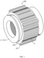
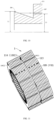
- a stator 100 includes a stator core 1 and a stator winding 2, and the stator core 1 includes a plurality of stator teeth 116 and a core oil passage 121 extending in an axial direction of the stator 100.
- the stator winding 2 is wound on the stator teeth 116, and a projection of the stator winding 2 and a projection of the core oil passage 121 in the axial direction of the stator 100 are at least partially overlapped.
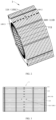
- the core oil passage 121 includes a spiral first oil passage section 103.
- the stator core 1 includes a first lamination 109 and a second lamination 110 stacked with each other.
- the first lamination 109 has a first oil hole 101 passing through the first lamination along the axial direction of the stator 100
- the second lamination 110 has a second oil hole 102 passing through the second lamination along the axial direction of the stator 100.
- the first oil hole 101 and the second oil hole 102 are staggered in a peripheral direction of the stator 100 and in partial communication with each other.
- At least one first lamination 109 is adjacent to at least one second lamination 110 to define the first oil passage section 103.
- the peripheral direction of the stator 100 refers to a circumferential direction surrounding an axis of the stator 100.
- the projection of the stator winding 2 and the projection of the core oil passage 121 in the axial direction of the stator 100 are at least partially overlapped, such that cooling oil in the core oil passage 121 is closer to the stator winding 2, which can realize the cooling and heat dissipation for the stator winding 2.
- the first oil hole 101 and the second oil hole 102 are staggered in the peripheral direction of the stator 100 and in partial communication with each other, such that S0 is greater than S1, and S0 is greater than S2.
- the core oil passage 121 extending in the axial direction of the stator 100 includes the spiral first oil passage section 103, such that the contact area between the cooling oil and the stator core 1 is increased compared with the related art in which the core oil passage 121 of the stator core is parallel to the axial direction of the stator core, thus improving the heat dissipation efficiency of the stator 100 and facilitating the reliable operation of the motor having the stator 100.
- stator 100 according to embodiments of the present invention has advantages of high heat dissipation efficiency and so on.
- a projection of at least one of the first oil hole 101 and the second oil hole 102 in the axial direction of the stator 100 has a circular shape, a rectangular shape, a T-shape or a cross-shape.
- a projection of at least one of the first oil hole 101 and the second oil hole 102 in the axial direction of the stator 100 has a circular shape, a rectangular shape, a T-shape or a cross-shape, which can be understood as: a projection of the first oil hole 101 in the axial direction of the stator 100 has a circular shape, a rectangular shape, a T-shape or a cross-shape, and a projection of the second oil hole 102 in the axial direction of the stator 100 has a shape other than any of the circular shape, the rectangular shape, the T-shape and the cross-shape; or, the projection of the second oil hole 102 in the axial direction of the stator 100 has a circular shape, a rectangular shape, a T-shape or a cross-shape, and the projection of the first oil hole 101 in the axial direction of the stator 100 has a shape other than any of the circular shape, the rectangular shape, the T-shape and the cross-shap
- each of the projection of the first oil hole 101 and the projection of the second oil hole 102 in the axial direction of the stator 100 has a rectangular shape.
- the projection of at least one of the first oil hole 101 and the second oil hole 102 in the axial direction of the stator 100 has the circular shape, the rectangular shape, the T-shape or the cross-shape, such that it is convenient to process and manufacture the first oil hole 101 and the second oil hole 102, which is conducive to reducing the cost of the stator 100 according to embodiments of the present invention.
- a plurality of first laminations 109 and a plurality of second laminations 110 are provided, and at least part of the first laminations 109 and at least part of the second laminations 110 are sequentially and alternately arranged along the axial direction of the stator 100 to define the first oil passage section 103.
- a plurality of first laminations 109 and a plurality of second laminations 110 are provided, and the number of the first laminations 109 and the number of the second laminations 110 are equal.
- the plurality of first laminations 109 and the plurality of the second laminations 110 are sequentially and alternately arranged along the axial direction of the stator 100 to define the first oil passage section 103.
- the plurality of first laminations 109 and the plurality of the second laminations 110 are sequentially and alternately arranged along the axial direction of the stator 100 to define the first oil passage section 103, such that a length of the first oil passage section 103 is longer, and hence the contact area between the cooling oil and the stator core 1 is larger, thus further improving the heat dissipation efficiency of the stator core 1.
- the core oil passage 121 further includes a second oil passage section 104.
- first laminations 109 are sequentially adjacent along the axial direction of the stator 100, and the first oil holes 101 of the adjacent first laminations 109 are aligned in the peripheral direction of the stator 100 to define the second oil passage section 104.
- a part of the first laminations 109 and a part of the second laminations 110 are sequentially and alternately arranged along the axial direction of the stator 100 to define the first oil passage section 103, and another part of the second laminations 109 are sequentially adjacent along the axial direction of the stator 100 to define a straight through second oil passage section 104.
- the straight through second oil passage section 104 has a smaller flow resistance for the cooling oil, which is conducive to the rapid flow of the cooling oil.
- the cooling oil has a higher heat dissipation efficiency for the stator core 1.
- a part of the second laminations 110 are sequentially adjacent, and the second oil holes 102 of the adjacent second laminations 110 are aligned in the peripheral direction of the stator 100 to define the second oil passage section 104.
- the core oil passage 121 includes the first oil passage section 103 and the second oil passage section 104, such that the heat dissipation efficiency of the stator core 1 and the flow rate of the cooling oil can be balanced by setting the length of the first oil passage section 103 and the length of the second oil passage section 104.
- first oil passage sections 103 are provided, and at least one second oil passage section 104 is between two adjacent first oil passage sections 103 in the axial direction of the stator 100.
- first oil passage sections 103 are provided, and the second oil passage section 104 is between the two first oil passage sections 103 in the axial direction of the stator 100.
- a plurality of second oil passage sections 104 are provided, and at least one first oil passage section 103 is between two adjacent second oil passage sections 104 in the axial direction of the stator 100.
- the plurality of first oil passage sections 103 are provided, and at least one second oil passage section 104 is between two adjacent first oil passage sections 103; or, the plurality of second oil passage sections 104 are provided, and at least one first oil passage section 103 is between two adjacent second oil passage sections 104, such that the heat dissipation efficiency of the stator core 1 and the flow rate of the cooling oil can be balanced by setting the number and the relative position of the first oil passage sections 103 and the second oil passage sections 104.
- the core oil passage 121 passes through the stator core 1 along the axial direction of the stator 100, and at least one port of the core oil passage 121 defines a core oil outlet 105.
- the stator winding 2 includes a winding end 201, and the winding end 201 is at a side of the stator core 1 in the axial direction of the stator 100.
- a projection of the core oil outlet 105 and the projection of the winding end in the axial direction of the stator 100 are at least partially overlapped.
- the stator 100 includes the stator winding 2, the stator winding 2 has the winding end 201, and the winding end 201 is at a side of the stator core 1 in the axial direction of the stator 100.
- the projection of the core oil outlet 105 and the projection the winding end 201 in the axial direction of the stator 100 are at least partially overlapped, such that the cooling oil flowing from the core oil outlet 105 may be sprayed to the winding end 201, thus realizing the cooling and heat dissipation of the winding end 201, and improving the utilization rate of the cooling oil and the heat dissipation efficiency of the stator 100.
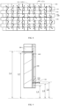
- the core oil passage 121 includes a first portion 106 and a second portion 107 arranged along the axial direction of the stator.
- the core oil outlet 105 is arranged in the second portion 107.
- the first portion 106 is father away from the axis of the stator 100 than the second portion 107.
- the stator 100 includes the stator winding 2, the stator winding 2 has the winding end 201, and the winding end 201 is at a side of the stator core 1 in the axial direction of the stator 100.
- a maximum distance between an outer side of the winding end 201 and the axis of the stator 100 is L1
- a minimum distance between the first portion 106 and the axis of the stator 100 is L2
- a minimum distance between the second portion 107 and the axis of the stator 100 is L3
- L2 is greater than L1
- L3 is less than L1, such that the first portion 106 is closer to the axis of the stator 100 than the second portion 107 in the axial direction of the stator 100.
- the cooling oil in the core oil passage 121 flows from the core oil outlet 105 of the second portion 107, the cooling oil may be sprayed to the winding end 201 of the stator winding 2 along the axial direction of the stator 100 to realize the cooling and heat dissipation of the winding end 201, thus further improving the utilization rate of the cooling oil and the heat dissipation efficiency of the stator 100.
- the stator core 1 includes a yoke portion 117 and stator teeth 116 coupled to each other.
- the first portion 106 is in the yoke portion 117, and at least part of the second portion 107 is in the stator teeth 116.
- At least part of the second portion 107 is in the stator teeth 116, which can be understood as: a part of the second portion 107 is in the yoke portion 117, and the other part of the second portion 107 is in the stator teeth 116; or, the second portion 107 is wholly in the stator teeth 116.
- the whole core oil passage 121 is generally arranged at a position close to the stator teeth 116, or even in the stator teeth 116.
- the setting position of the core oil passage 121 will affect the electromagnetic performance of the stator 100, and thus affect the performance of the motor.
- the core oil passage 121 includes the first portion 106 and the second portion 107, the first portion 106 is in the yoke portion 117, and at least part of the second portion 107 is in the stator teeth 116, such that the cooling oil from the core oil outlet 105 may be sprayed to the winding end 201 to cool the winding end 201, while avoiding that the core oil passage 121 is too close to the stator teeth 116, which is conducive to improving the electromagnetic performance of the stator 100 and thus the performance of the motor.
- the first portion 106 and the second portion 107 are staggered in a radial direction of the stator 100.
- the core oil passage 121 further includes a third portion 108, and the third portion 108 is between the first portion 106 and the second portion 107 in the axial direction of the stator 100.
- the first portion 106 is in communication with the second portion 107 through the third portion 108.
- the first portion 106 is at an outer side of the second portion 107, an outer end of the third portion 108 is in communication with the first portion 106, and an inner end of the third portion 108 is in communication with the second portion 107.
- the third portion 108 is utilized to realize the communication of the first portion 106 and the second portion 107.
- Inner refers to a side close to the axis of the stator 100 on a plane perpendicular to the axis of the stator 100
- outer refers to a side away from the axis of the stator 100 on the plane perpendicular to the axis of the stator 100.
- a minimum distance between the first portion 106 and the axis of the stator 100 is L2
- a distance between the outer end of the third portion 108 and the axis of the stator 100 is L4
- a distance between the inner end of the third portion 108 and the axis of the stator 100 is L5
- a maximum distance between the second portion 107 and the axis of the stator 100 is L6, L4 is greater than L2, and L5 is less than L6, such that the communication of the first portion 106 and the second portion 107 is realized through the third portion 108.
- the first portion 106 and the second portion 107 are staggered in the radial direction of the stator 100, such that it is convenient to arrange the first portion 106 farther away from the stator teeth 116, which is conducive to improving the electromagnetic performance of the stator 100 and thus the performance of the motor.
- the communication of the first portion 106 and the second portion 107 is conveniently realized by arrangement of the third portion 108.
- a part of the third portion 108 is in the yoke portion 117, and the other part of the third portion 108 is in the stator teeth 116.
- the third portion 108 includes an inner side portion 1081 and an outer side portion 1082, the inner side portion 1081 is in the stator teeth 116 and the outer side portion 1082 is in the yoke portion 117.
- a part of the third portion 108 is in the yoke portion 117, and the other part of the third portion 108 is in the stator teeth 116, such that the third portion 108 is arranged farther away from the stator teeth 116 under the condition that the communication of the first portion 106 and the second portion 107 is realized through the third portion 108 conveniently, which is conducive to improving the electromagnetic performance of the stator 100 and thus the performance of the motor.
- the first portion 106 includes at least one of the first oil passage section 103 and the second oil passage section 104.
- the first portion 106 includes at least one of the first oil passage section 103 and the second oil passage section 104, which can be understood as: the first portion 106 only includes the first oil passage section 103, and does not include the second oil passage section 104; or, the first portion 106 only includes the second oil passage section 104 and does not include the first oil passage section 103; or, the first portion 106 includes both the first oil passage section 103 and the second oil passage section 104.
- a plurality of core oil passages 121 are provided, and the plurality of core oil passages 121 are arranged along the peripheral direction of the stator 100.
- Each of the core oil passages 121 includes the first oil passage section 103, and first oil passage sections 103 of the plurality of core oil passages 121 are in communication with each other.
- the plurality of core oil passages 121 are arranged along the peripheral direction of the stator 100, such that the cooling oil may be supplied to the plurality of core oil passages 121, and the cooling oil in the plurality of core oil passages 121may be used for heat exchange with the stator core 1, which is conducive to improving the heat dissipation efficiency of the stator core 1.
- the first oil passage sections 103 of the plurality of core oil passages 121 are in communication with each other, such that the cooling oil can be supplied to the plurality of core oil passages 121 through one core oil inlet 114 in communication with one of the first oil passage sections 103, thus facilitating the supply of oil to the plurality of core oil passages 121.
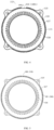
- a plurality of first oil holes 101 are provided in each first lamination 109, and the plurality of first oil holes 101 in a same first lamination 109 are spaced apart along the peripheral direction of the stator 100.
- a first interval 1093 is defined between two adjacent first oil holes 101 in the same first lamination 109.
- a plurality of second oil holes 102 are provided in each second lamination 110, and the plurality of second oil holes 102 in a same second lamination 110 are spaced apart along the peripheral direction of the stator 100.
- a second interval 1101 is defined between two adjacent second oil holes 102 in the same second lamination 110.
- each first interval 1093 is arranged corresponding to an adjacent second oil hole 102 in the peripheral direction of the stator 100, and each second interval 1101 is arranged corresponding to an adjacent first oil hole 101 in the peripheral direction of the stator 100.
- each first interval 1093 is arranged corresponding to the adjacent second oil hole 102 in the peripheral direction of the stator 100
- each second interval 1101 is arranged corresponding to the adjacent first oil hole 101 in the peripheral direction of the stator 100, such that each first oil hole 101 is in communication with two adjacent second oil holes 102 in the same second lamination 110, and each second oil hole 102 is in communication with two adjacent first oil holes 101 in the same first lamination 109. Therefore, the first oil passage sections 103 of the plurality of core oil passages 121 are in communication with each other.
- the size of the first interval 1093 is smaller than the size of the first oil hole 101 and the size of the second oil hole 102
- the size of the second interval 1101 is smaller than the size of the first oil hole 101 and the size of the second oil hole 102, such that each first oil hole 101 is in communication with two adjacent second oil holes 102, and each second oil hole 102 is in communication with two adjacent first oil holes 101, and hence the first oil passage sections 103 of the plurality of core oil passages 121 are in communication with each other.
- first lamination 109 and the second lamination 110 it is not only convenient to realize the communication of the first oil passage sections 103 of the plurality of core oil passages 121, but also conducive to further improving the contact area between the cooling oil and the stator core 1, thus further improving the heat dissipation efficiency of the stator core 1.
- first lamination 109 and the second lamination 110 have an identical structure, and the first lamination 109 and the second lamination 110 adjacent to each other are staggered at a preset angle in the peripheral direction of the stator 100 to define the first oil passage section 103.
- the size of the first interval 1093 and the size of the second interval 1101 are identical, the size of the first oil hole 101 and the size of the second oil hole 102 are identical, and each first oil hole 101 is located at a middle of two adjacent second oil holes 102.
- the first lamination 109 and the second lamination 110 have the identical structure, such that only a same type of laminations needs to be designed and manufactured, and the first oil passage section 103 may be formed by stacking the laminations, which is convenient for the design and manufacture of the stator core 1 and is conducive to reducing the cost of the stator core 1.
- each of two ports of the core oil passage 121 defines the core oil outlet 105.
- the stator core 1 has the core oil inlet 114 in communication with the core oil passage 121.
- the core oil inlet 114 is located between two core oil outlets 105 of the core oil passage 121 in the axial direction of the stator 100.
- a position of the core oil inlet 114 in the axial direction of the stator 100 depends on the uniformity requirement of the stator 100 for the cooling oil flow at two ends of the stator 100.
- the core oil inlet 114 is preferably in the middle of the stator core 1.
- the core oil inlet 114 may be arranged close to a side in the axial direction of the stator 100 according to the actual requirement.
- the core oil inlet 114 is between the two core oil outlets 105 of the core oil passage 121, such that it is convenient to set the position of the core oil inlet 114 according to the cooling requirement of the stator 100, thus achieving the cooling and heat dissipation of the stator 100 more effectively.
- At least one core oil inlet 114 is arranged close to a side of the stator core 1 in the axial direction of the stator 100.
- At least one core oil inlet 114 is arranged close to a side of the stator core 1 in the axial direction of the stator 100, which can be understood as: when one core oil inlet 114 is provided, the core oil inlet 114 is arranged close to a side of the stator core 1 in the axial direction of the stator 100; when a plurality of core oil inlets 114 are provided, each of the plurality of core oil inlets 114 may be arranged close to a side of the stator core 1 in the axial direction of the stator 100, or a part of the plurality of core oil inlets 114 may be arranged close to a side of the stator core 1 in the axial direction of the stator 100, and the other part of the plurality of core oil inlets 114 are located in the middle of the stator core 1 in the axial direction of the stator 100.
- two core oil inlets 114 are provided, one of the two core oil inlets 114 is in the middle of the stator core 1 in the axial direction of the stator 100, and the other of the two core oil inlets 114 is arranged close to a side of the stator core 1 in the axial direction of the stator 100.
- At least one core oil inlet 114 is a middle oil inlet, and the middle oil inlet is equidistant from the two core oil outlets 105 of the core oil passage 121 in the axial direction of the stator 100.
- At least one core oil inlet 114 is a middle oil inlet, which can be understood as: when one core oil inlet 114 is provided, the core oil inlet 114 is the middle oil inlet; when a plurality of core oil inlets 114 are provided, each of the plurality of core oil inlets 114 may be the middle oil inlet, or a part of the plurality of core oil inlets 114 may be middle oil inlets, and the other part of the plurality of core oil inlets 114 are arranged close to a side of the stator core 1 in the axial direction of the stator 100.
- one core oil inlet 114 is provided, the one core oil inlet 114 is the middle oil inlet, and the middle oil inlet is in the middle of the stator core 1 in the axial direction of the stator 100.
- two core oil inlets 114 are provided, one of the two core oil inlets 114 is the middle oil inlet, and the middle oil inlet is in the middle of the stator core 1 in the axial direction of the stator 100.
- the core oil inlet 114 is an oil inlet groove 1091 with an opening facing outwards, and the oil inlet groove 1091 has groove side walls 10911 opposite to each other in the peripheral direction of the stator 100.
- the stator core 1 further includes a third lamination 113, and the third lamination 113 is stacked with the first lamination 109 and the second lamination 110.
- the third lamination 113 has a communicating groove passing through the third lamination 113 along the axial direction of the stator 100, and the communicating groove defines the oil inlet groove 1091.
- the stator core 1 further includes the third lamination 113, and the third lamination 113 has the communicating groove passing through the third lamination 113 along the axial direction of the stator 100.
- the communicating groove has a first groove opening 10912 and a second groove opening 10913 opposite to each other in the axial direction of the stator 100.
- the third lamination 113 is stacked with the first lamination 109 and the second lamination 110, the first groove opening 10912 of the communicating groove is in communication with the first oil hole 101 of the first lamination 109, and the second groove opening 10913 of the communicating groove is in communication with the second oil hole 102 of the second lamination 110.
- the oil inlet groove 1091 may be defined by one communicating groove or a plurality of communicating grooves.
- the communicating groove is the oil inlet groove 1091;
- the stator core 1 further includes a plurality of third laminations 113, and the plurality of third laminations 113 are stacked with each other sequentially.
- the communicating grooves in the plurality of third laminations 113 are aligned in the peripheral direction of the stator 100, such that the plurality of communicating grooves define the oil inlet groove 1091.
- the communicating grooves of the third laminations 113 located at two ends in the axial direction of the stator 100 are in communication with the first oil hole 101 of the first lamination 109 and the second oil hole 102 of the second laminate on 110, respectively.
- the third lamination 113 may be selected according to the position of the core oil inlet 114 when assembling the stator core 1, to define the core oil inlet 114. Therefore, it is convenient to design and manufacture the stator core 1, and it is conducive to reducing the cost of the stator core 1.
- the core oil inlet 114 is an oil-inlet annular groove 1092 with an opening facing outwards, and the oil-inlet annular groove 1092 surrounds the peripheral direction of the stator 100 and is in communication with the plurality of core oil passages 121.
- the stator core 1 further includes the third lamination 113, and the third lamination 113 is stacked with the first lamination 109 and the second lamination 110.
- the third lamination 113 is between the first lamination 109 and the second lamination 110 in the axial direction of the stator 100.
- An outer diameter of the third lamination 113 is smaller than an outer diameter of the first lamination 109 and an outer diameter of the second lamination 110, such that the third lamination 113, the first lamination 109 and the second lamination 110 define the oil-inlet annular groove 1092.
- the oil-inlet annular groove 1092 has a first groove wall 10921 and a second groove wall 10922 opposite to each other in the axial direction of the stator 100.
- the first oil hole 101 of one first lamination 109 is in the first groove wall 10921
- the second oil hole of one second lamination 110 is in the second groove wall 10922, to communicate the oil-inlet annular groove 1092 with the core oil passage 121.
- the oil-inlet annular groove 1092 may be defined by one third lamination 113, one first lamination and one second lamination 110, or defined by a plurality of third laminations 113, one first lamination 109 and one second lamination 110.
- the third lamination 113 is located between the first lamination 109 and the second lamination 110 in the axial direction of the stator 100.
- the oil-inlet annular groove 1092 is defined by a plurality of third laminations 113, one first lamination 109 and one second lamination 110, the plurality of third laminations 113 are located between the first lamination 109 and the second lamination 110 in the axial direction of the stator 100.
- the third lamination 113 is between two adjacent first laminations 109 in the axial direction of the stator 100, and the outer diameter of the third lamination 113 is smaller than the outer diameters of the first laminations 109, such that the third lamination 113 and the adjacent two first laminations 109 define the oil-inlet annular groove 1092.
- the oil-inlet annular groove 1092 has the first groove wall 10921 and the second groove wall 10922 opposite to each other in the axial direction of the stator 100.
- the first oil hole 101 of one of the first laminations 109 is in the first groove wall 10921, and the first oil hole 101 of one of the first laminations 109 is in the second groove wall 10922, to communicate the oil-inlet annular groove 1092 with the core oil passage 121.
- the oil-inlet annular groove 1092 may be defined by one third lamination 113 and two first laminations, or defined by a plurality of third laminations 113 and two first laminations 109.
- the third lamination 113 is located between the two first laminations 109 in the axial direction of the stator 100.
- the oil-inlet annular groove 1092 is defined by a plurality of third laminations 113 and two first laminations 109, the plurality of third laminations 113 are located between the two first laminations 109 in the axial direction of the stator 100.
- the third lamination 113 is between two adjacent second laminations 110 in the axial direction of the stator 100, and the outer diameter of the third lamination 113 is smaller than the outer diameters of the second laminations 110, such that the third lamination 113 and the two adjacent second laminations 110 define the oil-inlet annular groove 1092.
- the oil-inlet annular groove 1092 has the first groove wall 10921 and the second groove wall 10922 opposite to each other in the axial direction of the stator 100.
- the second oil hole 102 of one of the second laminations 110 is in the first groove wall 10921, and the second oil hole 102 of one of the second laminations 110 is in the second groove wall 10922, to communicate the oil-inlet annular groove 1092 with the core oil passage 121.
- the oil-inlet annular groove 1092 may be defined by one third lamination 113 and two second laminations 110, or defined by a plurality of third laminations 113 and two second laminations 110.
- the third lamination 113 is located between the two second laminations 110 in the axial direction of the stator 100.
- the oil-inlet annular groove 1092 is defined by a plurality of third laminations 113 and two second laminations 110, the plurality of third laminations 113 are located between the two second laminations 110 in the axial direction of the stator 100.
- the third lamination 113 may be selected according to the position of the core oil inlet 114 when assembling the stator core 1, to define the core oil inlet 114. Therefore, it is convenient to design and process the stator core 1, and it is conducive to reducing the cost of the stator core 1.
- the third lamination 113 has a plurality of third oil holes 118, and a plurality of third oil holes 118 are provided in each third lamination 113.
- the plurality of third oil holes 118 in a same third lamination 113 are spaced apart along the peripheral direction of the stator 100, and a third interval 1131 is defined between two adjacent third oil holes 118 in the same third lamination 113.
- a size of the third interval 1131 and the size of the first interval are identical, and a size of the third oil hole 118 and the size of the first oil hole 101 are identical.
- the difference between the third lamination 113 and the first lamination 109 and the second lamination 110 is that the third lamination 113 has a structure configured to define the core oil inlet 114, i.e., compared with the first lamination 109 and the second lamination 110, the third lamination 113 has the communicating groove or the outer diameter of the third lamination 113 is smaller than the outer diameter of the first lamination 109 and the outer diameter of the second lamination 110.
- the third oil hole 118 and the first oil hole 101 are staggered in the peripheral direction of the stator 100 and in partial communication with each other.
- the third oil hole 118 and the second oil hole 101 are staggered in the peripheral direction of the stator core 1 and in partial communication with each other.
- the third oil hole 118 and the first oil hole 101 are aligned in the peripheral direction of the stator 100.
- the third oil hole 118 and the second oil hole 101 are aligned in the peripheral direction of the stator core 1.
- the stator core 1 further includes a plurality of fourth laminations 111, and the plurality of fourth laminations 111 are stacked with each other.
- the fourth lamination 111 has a plurality of fourth oil holes 119.
- the plurality of fourth oil holes 119 in a same fourth lamination 111 are spaced apart along the peripheral direction of the stator 100.
- the fourth oil holes 119 in adjacent fourth laminations 111 are in one-to-one correspondence and in communication with each other, to define the second portion 107.
- the fourth oil holes 119 in adjacent fourth laminations 111 are in one-to-one correspondence and in communication with each other, which can be understood as: corresponding fourth oil holes 119 are aligned in the peripheral direction of the stator 100, such that the second portion 107 is a straight through type; or, the corresponding fourth oil holes 119 are staggered in the peripheral direction of the stator 100 and in partial communication with each other, such that the second portion 107 is a spiral structure.
- the stator core 1 further includes a plurality of fifth laminations 112, and the plurality of fifth laminations 112 are stacked with each other.
- the fifth lamination 112 has a plurality of fifth oil holes 120, and the plurality of fifth oil holes 120 in a same fifth lamination 112 are spaced apart along the peripheral direction of the stator 100.
- the fifth oil holes 120 in adjacent fifth laminations 112 are in one-to-one correspondence and in communication with each other, to define the third portion 108.
- the fifth oil holes 120 in adjacent fifth laminations 112 are in one-to-one correspondence and in communication with each other, which can be understood as: corresponding fifth oil holes 120 are aligned in the peripheral direction of the stator 100, such that the third portion 108 is a straight through type; or, the corresponding fifth oil holes 120 are staggered in the peripheral direction of the stator 100 and in partial communication with each other, such that the third portion 108 is a spiral structure.
- the stator 100 is composed by stacking and compressing perforated laminations (the first lamination 109, the second lamination 110, the third lamination 113, the fourth lamination 111 and the fifth lamination 112), and the laminations may be reliably coupled by welding, riveting, bonding or other processes.
- the core oil inlet 114 may be formed by stamping on the lamination, or by other processes such as machining or wire cutting.
- the first portion 106 may only include the first oil passage section 103.
- the first portion 106 may adopt a combined design including the first oil passage section 103 and the second oil passage section 104.
- the cooling oil enters along the radial direction of the stator 100, flows through the core oil passage 121 to the core oil outlets 105 at two ends of the stator core 1, and is sprayed out from the core oil outlet 105 to directly cool the winding end 201 of the stator winding 2. Since no other parts are needed to define a closed oil cavity, the design of parts in the system is greatly simplified and the heat dissipation capacity is improved. Both the stator winding 2 and the stator core 1 are fully and evenly cooled, thus effectively reducing the risk of high temperature aging failure of the motor insulation, and improving the power density and torque density of the motor 1000 simultaneously.
- a motor 1000 includes a housing 400 and a stator 100.
- the housing 400 has a first housing oil inlet 401, the stator 100 is in the housing 400, the stator 100 is a stator 100 of any of the above described embodiments, and the core oil passage 121 is in communication with the first housing oil inlet 401.
- the motor 1000 according to embodiments of the present invention has advantages of a high reliability and so on.
- the stator 100 and the housing 400 may be fixed by adopting an interference fit, a bolt or a key.
- the stator 100 has a coupling hole 115, and the stator 100 is fixedly coupled to the housing 400 through a bolt passing through the coupling hole 115.
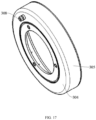
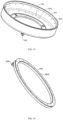
- the motor 1000 further includes an oil spraying ring 3, and the oil spraying ring 3 is in the housing 400.
- the oil spraying ring 3 is on at least one side of the stator core 1 in the axial direction of the stator 100.
- the oil spraying ring 3 has an oil ring channel 307, an oil ring inlet 308 and an oil spraying hole 310.
- Each of the oil ring inlet 308 and the oil spraying hole 310 is in communication with the oil ring channel 307.
- the oil spraying hole 310 is oriented towards the winding end 201 to spray the cooling oil to the winding end 201.
- the oil ring inlet 308 is in communication with the core oil passage 121, and/or the housing 400 has a second housing oil inlet 402 in communication with the oil ring inlet 308.
- the oil ring inlet 308 is in communication with the core oil passage 121, and/or the housing 400 has a second housing oil inlet 402 in communication with the oil ring inlet 308, which can be understood as: the oil ring inlet 308 is in communication with the core oil passage 121, and the housing 400 does not have a second housing oil inlet 402. At this time, the oil ring inlet 308 is in communication with the core oil passage 121, and the cooling oil may be supplied to the oil ring channel 307 through the core oil passage 121; or, the oil ring inlet 308 is not in communication with the core oil passage 121, but the housing 400 has the second housing oil inlet 402.
- the oil ring inlet 308 is in communication with the second housing oil inlet 402, and the cooling oil may be supplied to the oil ring channel 307 through the second housing oil inlet 402; or, the oil ring inlet 308 is in communication with the core oil passage 121, and the housing 400 has the second housing oil inlet 402.
- the oil ring inlet 308 is in communication with each of the core oil passage 121 and the second housing oil inlet 402, and the cooling oil may be supplied to the oil ring channel 307 through the second housing oil inlet 402 and the core oil passage 121.
- the cooling oil is supplied to the oil ring channel 307, such that the cooling oil in the oil ring channel 307 may be sprayed to the winding end 201 through the oil spraying hole 310 to cool the winding end 201 and dissipate the heat of the winding end 201.
- the arrangement of the oil spraying ring 3 can further improve the cooling and heat dissipation effect of the stator 100, which is conducive to further improving the reliability of the motor 1000 having the stator 100.
- the two oil spraying rings 3 are a first oil spraying ring 301 and a second oil spraying ring 302, respectively.
- the first oil spraying ring 301 and the second oil spraying ring 302 are at two sides of the stator core 1 in the axial direction of the stator 100, respectively.
- the first oil spraying ring 301 may realize the cooling and heat dissipation of the winding end 201 on a side of the stator core 1
- the second oil spraying ring 302 may realize the cooling and heat dissipation of the winding end 201 on the other side of the stator core 1.
- first oil spraying ring 301 and the second oil spraying ring 302 have an identical structure and an identical size.
- the oil spraying ring 3 has an accommodating groove 303 with an opening facing towards the stator core 1, and at least part of the winding end 201 is in the accommodating groove 303.
- a plurality of oil spraying holes 310 are provided.
- a part of the plurality of oil spraying holes 310 are an axial oil spraying hole 3041 extending in the axial direction of the stator 100, and the other part of the plurality of oil spraying holes 310 are a radial oil spraying hole 311 extending in the radial direction of the stator 100.
- the axial oil spraying hole is in a groove bottom wall 3031 of the accommodating groove 303, and the radial oil spraying hole 311 is in the groove side wall 3032 of the accommodating groove 303.
- At least part of the winding end 201 is in the accommodating groove 303, which can be understood as: a part of the winding end 201 is in the accommodating groove 303, and the other part of the winding end 201 is outside the accommodating groove 303; or, the winding end 201 is wholly in the accommodating groove 303.
- At least part of the winding end 201 is in the accommodating groove 303, and the axial oil spraying hole is in the groove bottom wall 3031 of the accommodating groove 303, such that the cooling oil may be sprayed to the winding end 201 along the axial direction of the stator 100; the radial oil spraying hole 311 is in the groove side wall 3032 of the accommodating groove 303, such that the cooling oil may be sprayed to the winding end 201 along the radial direction of the stator 100, thus realizing the cooling and heat dissipation of many portions of the winding end 201, which is conducive to further improving the cooling and heat dissipation effect of the stator 100 and to further improving the reliability of the motor 1000 having the stator 100.
- the groove side wall 3032 includes an inner groove wall 30321 and an outer groove wall 30322, the inner groove wall 30321 and the outer groove wall 30322 are spaced apart, and the inner groove wall 30321 is at an inner side of the outer groove wall 30322.
- a plurality of radial oil spraying holes 311 are provided, a part of the plurality of radial oil spraying holes 311 are an inner oil spraying hole 3061, and the other part of the plurality of radial oil spraying holes 311 are an outer oil spraying hole 3051.
- the inner oil spraying hole 3061 is in an outer side face of the inner groove wall 30321, and the outer oil spraying hole 3051 is in an inner side face of the outer groove wall 30322.
- the inner oil spraying hole 3061 is in the inner groove wall 30321, such that the cooling oil in the oil ring channel may be sprayed to an inner side face of the winding end 201 through the inner oil spraying hole 3061, thus realizing the cooling and heat dissipation of the inner side face of the winding end 201.
- the outer oil spraying hole 3051 is in the outer groove wall 30322, such that the cooling oil in the oil ring channel may be sprayed to an outer side face of the winding end 201 through the outer oil spraying hole 3051, thus realizing the cooling and heat dissipation of the outer side face of the winding end 201.
- the design of the plurality of radial oil spraying holes 311 described above can more effectively realize the cooling and heat dissipation of the winding end 201, which is conducive to further improving the cooling and heat dissipation effect of the stator 100 and to further improving the reliability of the motor 1000 having the stator 100.
- a plurality of axial oil spraying holes 3041 are provided, and the plurality of axial oil spraying holes 3041 are spaced apart along the peripheral direction of the stator 100.
- a plurality of outer oil spraying holes 3051 are provided, and the plurality of outer oil spraying holes 3051 are spaced apart along the peripheral direction of the stator 100.
- a plurality of inner oil spraying holes 3061 are provided, and the plurality of inner oil spraying holes 3061 are spaced apart along the peripheral direction of the stator 100.
- each outer oil spraying hole 3051 and adjacent inner oil spraying hole 3061 are staggered in the peripheral direction of the stator 100.
- Each outer oil spraying hole 3051 and adjacent inner oil spraying hole 3061 are staggered in the peripheral direction of the stator 100, thus further facilitating the injection of the cooling oil by 360° along the peripheral direction of the winding end 201 to the winding end 201, which is conducive to further improving the cooling and heat dissipation effect of the stator 100 and to further improving the reliability of the motor 1000 having the stator 100.
- the oil spraying ring 3 includes a first barrel 305, a second barrel 306, and an annular plate 304.
- Each of the first barrel 305 and the second barrel 306 is coupled to the plate 304.
- the plate 304, the first barrel 305, and the second barrel 306 define the accommodating groove 303.
- the first barrel 305 defines the inner groove wall 30321, and the second barrel 306 defines the outer groove wall 30322.
- the overall structure of the oil spraying ring 3 is simple, which is convenient for the design and manufacture, and is conducive to reducing the cost of the stator 100.
- the plate 304 has a first cavity 3042
- the first barrel 305 has a second cavity 3052
- the second barrel 306 has a third cavity 3062.
- the first cavity 3042, the second cavity 3052 and the third cavity 3062 are in communication with each other, such that the plate 304, the first barrel 305 and the second barrel 306 define the oil ring channel 307.
- the oil ring inlet 308 is in the plate 304.
- the plate 304 is designed to have the first cavity 3042
- the first barrel 305 is designed to have the second cavity 3052
- the second barrel 306 is designed to have the third cavity 3062, such that the first cavity 3042, the second cavity 3052, and the third cavity 3062 are in communication with each other to define the oil ring channel, which further facilitates the design and manufacture of the oil spraying ring 3 and is conducive to reducing the cost of the stator 100.
- the plate 304, the first barrel 305 and the second barrel 306 are coupled by a plastic welding process.
- laser welding or infrared welding is preferred.
- an ultrasonic and vibration friction welding process or other processes may be used.
- part of the plate 304 is at an inner side of the inner groove wall 30321 to define a fixing portion 309, and the fixing portion 309 has a fixing hole 3091 configured for a fastener to pass through.
- part of the plate 304 is located at an inner side of the second barrel 306 to define the fixing portion 309, and the fixing portion 309 has the fixing hole 3091.
- the oil spraying ring 3 may be fixed to the housing 400 or other components through the fastener passing through the fixing hole 3091.
- the housing 400 has a threaded hole, and a screw passes through the fixing hole 3091 of the oil spraying ring 3 and is threaded with the threaded hole, thus realizing the fixed mounting of the oil spraying ring 3.
- the oil spraying ring 3 is further fixedly coupled to the stator core 1 through the fastener, or the oil spraying ring 3 may further be fixed to the housing 400 or the stator core 1 by means of a pressing plate or a squeezing fit.
- the oil spraying ring 3 may only include the plate 304 and the first barrel 305.
- the plate 304 has the axial oil spraying hole 3041, and the first barrel 305 has the outer oil spraying hole 3051.
- the oil ring inlet 308 may be in the plate 304.
- the oil spraying ring 3 only includes the plate 304, and the plate 304 has the axial oil spraying hole 3041.
- the oil ring inlet 308 is in the plate 304.
- the oil spraying ring 3 only includes the first barrel 305, and the first barrel 305 has the outer oil spraying hole 3051.
- the oil ring inlet 308 is in an end of the first barrel 305 facing away from the stator core 1.
- the oil spraying ring 3 only includes the second barrel 306, and the second barrel 306 has the inner oil spraying hole 3061.
- the oil ring inlet 308 is in an end of the second barrel 306 facing away from the stator core 1.
- the oil spraying ring 3 is made of oil resistant and high temperature resistant plastics, such as PA6, PA66, PBT, PPA, PPS.
- a metal may also be used in case of sufficient space and high strength requirements.
- the number, the size and the position of the oil spraying hole in the oil spraying ring 3 are designed according to the actual situation.
- the oil spraying ring 3 is sealed with the second housing oil inlet 402 through a sealing member.
- the sealing member may be an O-ring.
- the oil spraying ring 3 may also be coupled to the second housing oil inlet 402 by means of a small clearance fit or a transition fit.
- the motor 1000 according to embodiments of the present invention has the following advantages:
- a vehicle according to embodiments of the present invention includes a vehicle body and a motor 1000.
- the motor 1000 is on the vehicle body, and the motor 1000 is a motor 1000 of any of the above-described embodiments.
- the motor 1000 may be used as power of the vehicle.
- the vehicle according to embodiments of the present invention has advantages of a high reliability and so on.
- first and second are only used for descriptive purposes and cannot be understood as indicating or implying relative importance or implicitly indicating the number of indicated technical features.
- the features defined by “first” and “second” may include at least one of the features explicitly or implicitly.
- a plurality of means at least two such as two or three, unless otherwise expressly and specifically defined.
- terms such as “mounted,” “connected,” “coupled,” and “fixed” shall be understood broadly, and may be, for example, fixed connections, detachable connections, or integral connections; may also be mechanical or electrical connections or intercommunication; may also be direct connections or indirect connections via intervening media; may also be inner communications or interactions of two elements.
- mounted may be, for example, fixed connections, detachable connections, or integral connections; may also be mechanical or electrical connections or intercommunication; may also be direct connections or indirect connections via intervening media; may also be inner communications or interactions of two elements.
- a structure in which a first feature is "on" or “below” a second feature may include an embodiment in which the first feature is in direct contact with the second feature, or may further include an embodiment in which the first feature and the second feature are in indirect contact through intermediate media.
- a first feature "on,” “above,” or “on top of” a second feature may include an embodiment in which the first feature is right or obliquely “on,” “above,” or “on top of” the second feature, or just means that the first feature is at a height higher than that of the second feature
- a first feature "below,” “under,” or “on bottom of” a second feature may include an embodiment in which the first feature is right or obliquely “below,” “under,” or “on bottom of” the second feature, or just means that the first feature is at a height lower than that of the second feature.
Landscapes
- Engineering & Computer Science (AREA)
- Power Engineering (AREA)
- Iron Core Of Rotating Electric Machines (AREA)
Claims (14)
- Ein Stator (100), der folgende Merkmale aufweist:einen Statorkern (1), der eine Mehrzahl von Statorzähnen (116) und einen Kernöldurchgang (121) aufweist, der sich in einer Axialrichtung des Stators (100) erstreckt; undeine Statorwicklung (2), die auf die Mehrzahl von Statorzähnen (116) gewickelt ist, wobei sich ein Vorsprung der Statorwicklung (2) und ein Vorsprung des Kernöldurchgangs (121) in der Axialrichtung des Stators (100) zumindest teilweise überlappen,wobei der Kernöldurchgang (121) einen spiralförmigen ersten Öldurchgangsabschnitt (103) aufweist, der Statorkern (1) eine erste Laminierung (109) und eine zweite Laminierung (110) aufweist, die miteinander gestapelt sind, die erste Laminierung (109) ein erstes Ölloch (101) aufweist, das entlang der Axialrichtung des Stators (100) durch die erste Laminierung (109) verläuft, die zweite Laminierung (110) ein zweites Ölloch (102) aufweist, das entlang der Axialrichtung des Stators (100) durch die zweite Laminierung (110) verläuft, das erste Ölloch (101) und das zweite Ölloch (102) in einer Umfangsrichtung des Stators (100) versetzt sind und in teilweiser Kommunikation miteinander sind, und zumindest eine erste Laminierung (109) benachbart zu zumindest einer zweiten Laminierung (110) ist, um den ersten Öldurchgangsabschnitt (103) zu definieren,wobei der Kernöldurchgang (121) entlang der Axialrichtung des Stators (100) durch den Statorkern (1) verläuft, und zumindest ein Anschluss des Kernöldurchgangs (121) einen Kernölauslass (105) definiert;die Statorwicklung (2) ein Wicklungsende (201) aufweist, und das Wicklungsende (201) in der Axialrichtung des Stators (100) an einer Seite des Statorkerns (1) ist; undein Vorsprung des Kernölauslasses (105) und ein Vorsprung des Wicklungsendes (201) in der Axialrichtung des Stators (100) zumindest teilweise überlappen;wobei der Kernöldurchgang (121) einen ersten Abschnitt (106) und einen zweiten Abschnitt (107) aufweist, wobei der erste Abschnitt (106) weiter von einer Achse des Stators (100) entfernt ist als der zweite Abschnitt (107) in der radialen Richtung des Stators (100), und der Kernölauslass (105) in dem zweiten Abschnitt (107) angeordnet ist;wobei der Statorkern (1) einen Jochabschnitt (117) aufweist, der mit den Statorzähnen (116) gekoppelt ist, der erste Abschnitt (106) in dem Jochabschnitt (117) ist, und zumindest ein Teil des zweiten Abschnitts (107) in den Statorzähnen (116) ist;wobei der erste Abschnitt (106) und der zweite Abschnitt (107) in einer radialen Richtung des Stators (100) versetzt sind, der Kernöldurchgang (121) ferner einen dritten Abschnitt (108) aufweist, und der erste Abschnitt (106) durch den dritten Abschnitt (108) mit dem zweiten Abschnitt (107) in Kommunikation ist;wobei ein Teil des dritten Abschnitts (108) in dem Jochabschnitt (117) ist, und der andere Teil des dritten Abschnitts (108) in den Statorzähnen (116) ist, und der erste Abschnitt (106) den ersten Öldurchgangsabschnitt (103) aufweist,dadurch gekennzeichnet, dass der erste Abschnitt (106) und der zweite Abschnitt (107) sich in der Axialrichtung jeweils an zwei Seiten des dritten Abschnitts (108) befinden, und der dritte Abschnitt (108) in der Axialrichtung des Stators (100) zwischen dem ersten Abschnitt (106) und dem zweiten Abschnitt (107) ist, und der dritte Abschnitt (108) ein radial äußeres Ende, das mit einem Ende des ersten Abschnitts (106) verbunden ist, und ein radial inneres Ende aufweist, das mit einem Ende des zweiten Abschnitts (107) verbunden ist.
- Der Stator (100) gemäß Anspruch 1, wobei eine Mehrzahl von ersten Laminierungen (109) und eine Mehrzahl von zweiten Laminierungen (110) vorgesehen sind, und zumindest ein Teil der ersten Laminierungen (109) und zumindest ein Teil der zweiten Laminierungen (110) sequentiell und abwechselnd entlang der Axialrichtung des Stators (100) angeordnet sind, um den ersten Öldurchgangsabschnitt (103) zu definieren.
- Der Stator (100) gemäß Anspruch 2, wobei der Kernöldurchgang (121) ferner einen geraden durchgehenden zweiten Öldurchgangsabschnitt (104) aufweist;ein Teil der ersten Laminierungen (109) sequentiell benachbart sind, und die ersten Öllöcher (101) von benachbarten ersten Laminierungen (109) in der Umfangsrichtung des Stators (100) ausgerichtet sind, um den zweiten Öldurchgangsabschnitt (104) zu definieren, und/oderein Teil der zweiten Laminierungen (110) sequentiell benachbart sind, und die zweiten Öllöcher (102) von benachbarten zweiten Laminierungen (110) in der Umfangsrichtung des Stators (100) ausgerichtet sind, um den zweiten Öldurchgangsabschnitt (104) zu definieren.
- Der Stator (100) gemäß Anspruch 3, wobei eine Mehrzahl von ersten Öldurchgangsabschnitten (103) vorgesehen ist, und zumindest ein zweiter Öldurchgangsabschnitt (104) in der Axialrichtung des Stators (100) zwischen zwei benachbarten ersten Öldurchgangsabschnitten (103) ist; und/oder
eine Mehrzahl von zweiten Öldurchgangsabschnitten (104) vorgesehen ist, und zumindest ein erster Öldurchgangsabschnitt (103) in der Axialrichtung des Stators (100) zwischen zwei benachbarten zweiten Öldurchgangsabschnitten (104) ist. - Der Stator (100) gemäß einem der Ansprüche 1 bis 4, wobei eine Mehrzahl von Kernöldurchgängen (121) vorgesehen ist, die Mehrzahl von Kernöldurchgängen (121) entlang der Umfangsrichtung des Stators (100) angeordnet ist, jeder der Kernöldurchgänge (121) den ersten Öldurchgangsabschnitt (103) aufweist, und die ersten Öldurchgangsabschnitte (103) der Mehrzahl von Kernöldurchgängen (121) in Kommunikation miteinander sind;vorzugsweise eine Mehrzahl von ersten Öllöchern (101) in jeder ersten Laminierung (109) vorgesehen ist, die Mehrzahl von ersten Öllöchern (101) in einer gleichen ersten Laminierung (109) entlang der Umfangsrichtung des Stators (100) beabstandet ist, und zwischen zwei benachbarten ersten Öllöchern (101) in der gleichen ersten Laminierung (109) ein erster Abstand (1093) definiert ist;eine Mehrzahl von zweiten Öllöchern (102) in jeder zweiten Laminierung (110) vorgesehen ist, die Mehrzahl von zweiten Öllöchern (102) in einer gleichen zweiten Laminierung (110) entlang der Umfangsrichtung des Stators (100) beabstandet ist, und zwischen zwei benachbarten zweiten Öllöchern (102) in der gleichen zweiten Laminierung (110) ein zweiter Abstand (1101) definiert ist;in der Umfangsrichtung des Stators (100) eine Größe des ersten Abstands (1093) kleiner ist als eine Größe des zweiten Öllochs (102), und eine Größe des zweiten Abstands (1101) kleiner ist als eine Größe des ersten Öllochs (101), in dem ersten Öldurchgangsabschnitt (103) jeder erste Abstand (1093) entsprechend einem benachbarten zweiten Ölloch (102) in der Umfangsrichtung des Stators (100) angeordnet ist, und jeder zweite Abstand (1101) entsprechend einem benachbarten ersten Ölloch (101) in der Umfangsrichtung des Stators (100) angeordnet ist, so dass die ersten Öldurchgangsabschnitte (103) der Mehrzahl von Kernöldurchgängen (121) in Kommunikation miteinander sind; undvorzugsweise die erste Laminierung (109) und die zweite Laminierung (110) eine identische Struktur aufweisen, und die erste Laminierung (109) und die zweite Laminierung (110) benachbart zueinander in einem voreingestellten Winkel in der Umfangsrichtung des Stators (100) versetzt sind, um den ersten Öldurchgangsabschnitt (103) zu definieren.
- Der Stator (100) gemäß Anspruch 5, wobei der Kernöldurchgang (121) entlang der Axialrichtung des Stators (100) durch den Statorkern (1) verläuft, jeder von zwei Anschlüssen des Kernöldurchgangs (121) einen Kernölauslass (105) definiert, der Statorkern (1) einen Kernöleinlass (114) in Kommunikation mit dem Kernöldurchgang (121) aufweist, und der Kernöleinlass (114) sich in der Axialrichtung des Stators (100) zwischen zwei Kernölauslässen (105) des Kernöldurchgangs (121) befindet.
- Der Stator (100) gemäß Anspruch 6, wobei zumindest ein Kernöleinlass (114) in der Axialrichtung des Stators (100) nahe an einer Seite des Statorkerns (1) angeordnet ist; und/oderzumindest ein Kernöleinlass (114) ein mittlerer Öleinlass ist, und der mittlere Öleinlass in der Axialrichtung des Stators (100) äquidistant von den zwei Kernölauslässen (105) des Kernöldurchgangs (121) ist; oderder Kernöleinlass (114) eine Öleinlassrille (1091) mit einer Öffnung ist, die nach außen gerichtet ist, und die Öleinlassrille (1091) Rillenseitenwände (10911) aufweist, die einander in der Umfangsrichtung des Stators (100) gegenüberliegen;vorzugsweise der Statorkern (1) ferner eine dritte Laminierung (113) aufweist, die dritte Laminierung (113) mit der ersten Laminierung (109) und der zweiten Laminierung (110) gestapelt ist, die dritte Laminierung (113) eine Kommunikationsrille aufweist, die entlang der Axialrichtung des Stators (100) durch die dritte Laminierung (113) verläuft, und die Kommunikationsrille die Öleinlassrille (1091) definiert.
- Der Stator (100) gemäß Anspruch 6 oder 7, wobei der Kernöleinlass (114) eine ringförmige Öleinlassrille (1092) mit einer Öffnung ist, die nach außen gerichtet ist, und die ringförmige Öleinlassrille (1092) die Umfangsrichtung des Stators (100) umgibt und mit der Mehrzahl von Kernöldurchgängen (121) in Kommunikation ist.
- Der Stator (100) gemäß Anspruch 8, wobei der Statorkern (1) ferner eine dritte Laminierung (113) aufweist und die dritte Laminierung (113) mit der ersten Laminierung (109) und der zweiten Laminierung (110) gestapelt ist;die dritte Laminierung (113) in der Axialrichtung des Stators (100) zwischen der ersten Laminierung (109) und der zweiten Laminierung (110) ist, und ein Außendurchmesser der dritten Laminierung (113) kleiner ist als ein Außendurchmesser der ersten Laminierung (109) und ein Außendurchmesser der zweiten Laminierung (110), so dass die dritte Laminierung (113), die erste Laminierung (109) und die zweite Laminierung (110) die ringförmige Öleinlassrille (1092) definieren, oderdie dritte Laminierung (113) in der Axialrichtung des Stators (100) zwischen zwei benachbarten ersten Laminierungen (109) ist, und der Außendurchmesser der dritten Laminierung (113) kleiner ist als die Außendurchmesser der ersten Laminierungen (109), so dass die dritte Laminierung (113) und die zwei benachbarten ersten Laminierungen (109) die ringförmige Öleinlassrille (1092) definieren, oderdie dritte Laminierung (113)) in der Axialrichtung des Stators (100) zwischen zwei benachbarten zweiten Laminierungen (110ist, und der Außendurchmesser der dritten Laminierung (113) kleiner ist als die Außendurchmesser der zweiten Laminierungen (110), so dass die dritte Laminierung (113) und die zwei benachbarten zweiten Laminierungen (110) die ringförmige Öleinlassrille (1092) definieren.
- Der Stator (100) gemäß einem der Ansprüche 1 bis 9, wobei ein Vorsprung von zumindest einem von dem ersten Ölloch (101) und dem zweiten Ölloch (102) in der Axialrichtung des Stators (100) eine Kreisform, eine Rechteckform, eine T-Form oder eine Kreuzform aufweist.
- Ein Motor (1000), der folgende Merkmale aufweist:ein Gehäuse (400) mit einem ersten Gehäuseöleinlass (401);einen Stator (100) gemäß einem der Ansprüche 1 bis 10, wobei der Stator (100) in dem Gehäuse (400) ist, und der Kernöldurchgang (121) mit dem ersten Gehäuseöleinlass (401) in Kommunikation ist.
- Der Motor (1000) gemäß Anspruch 11, wobei die Statorwicklung (2) ein Wicklungsende (201) aufweist, das Wicklungsende (201) in der Axialrichtung des Stators (100) an einer Seite des Statorkerns (1) ist, der Motor (1000) ferner einen Ölsprühring (3) aufweist, wobei der Ölsprühring (3) in dem Gehäuse (400) ist, der Ölsprühring (3) in der Axialrichtung des Stators (100) an zumindest einer Seite des Statorkerns (1) ist, und der Ölsprühring (3) einen Ölringkanal (307), einen Ölringeinlass (308) und ein Ölsprühloch (310) aufweist, wobei jeder von dem Ölringeinlass (308) und dem Ölsprühloch (310) mit dem Ölringkanal (307) in Kommunikation ist, und das Ölsprühloch (310) zu dem Wicklungsende (201) hin ausgerichtet ist, um das Kühlöl zu dem Wicklungsende (201) zu sprühen; undder Ölringeinlass (308) mit dem Kernöldurchgang (121) in Kommunikation ist, und/oderdas Gehäuse (400) einen zweiten Gehäuseöleinlass (402) in Kommunikation mit dem ÖIringeinlass (308) aufweist.
- Der Motor (1000) gemäß Anspruch 12, wobei der Ölsprühring (3) eine Aufnahmerille (303) mit einer Öffnung aufweist, die zu dem Statorkern (1) gerichtet ist, wobei zumindest ein Teil des Wicklungsendes (201) in der Aufnahmerille (303) ist, eine Mehrzahl von Ölsprühlöchern (310) vorgesehen ist, ein Teil der Mehrzahl von Ölsprühlöchern (310) ein axiales Ölsprühloch (3041) ist, das sich in der Axialrichtung des Stators (100) erstreckt, und der andere Teil der Mehrzahl von Ölsprühlöchern (310) ein radiales Ölsprühloch (311) ist, das sich in der radialen Richtung des Stators (100) erstreckt, das axiale Ölsprühloch (3041) in einer Rillenunterwand (3031) der Aufnahmerille (303) ist, und das radiale Ölsprühloch (311) in der Rillenseitenwand (3032) der Aufnahmerille (303) ist;vorzugsweise die Rillenseitenwand (3032) eine innere Rillenwand (30321) und eine äußere Rillenwand (30322) aufweist, die innere Rillenwand (30321) und die äußere Rillenwand (30322) beabstandet sind, und die innere Rillenwand (30321) an einer Innenseite der äußeren Rillenwand (30322) ist; undeine Mehrzahl von radialen Ölsprühlöchern (311) vorgesehen ist, ein Teil der Mehrzahl von radialen Ölsprühlöchern (311) ein inneres Ölsprühloch (3061) ist, der andere Teil der Mehrzahl von radialen Ölsprühlöchern (311) ein äußeres Ölsprühloch (3051) ist, das innere Ölsprühloch (3061) in einer äußeren Seitenfläche der inneren Rillenwand (30321) ist, und das äußere Ölsprühloch (3051) in einer inneren Seitenfläche der äußeren Rillenwand (30322) ist;vorzugsweise eine Mehrzahl von axialen Ölsprühlöchern (3041) vorgesehen ist, und die Mehrzahl von axialen Ölsprühlöchern (3041) entlang der Umfangsrichtung des Stators (100) beabstandet ist;eine Mehrzahl von äußeren Ölsprühlöchern (3051) vorgesehen ist, und die Mehrzahl von äußeren Ölsprühlöchern (3051) entlang der Umfangsrichtung des Stators (100) beabstandet ist; undeine Mehrzahl von inneren Ölsprühlöchern (3061) vorgesehen ist, und die Mehrzahl von inneren Ölsprühlöchern (3061) entlang der Umfangsrichtung des Stators (100) beabstandet ist;vorzugsweise jedes äußere Ölsprühloch (3051) und benachbarte innere Ölsprühloch (3061) in der Umfangsrichtung des Stators (100) versetzt sind; oderder Ölsprühring (3) einen ersten Zylinder (305), einen zweiten Zylinder (306) und eine ringförmige Platte (304) aufweist, jeder von dem ersten Zylinder (305) und dem zweiten Zylinder (306) mit der Platte (304) gekoppelt ist, die Platte (304), der erste Zylinder (305) und der zweite Zylinder (306) die Aufnahmerille (303) definieren, der erste Zylinder (305) die innere Rillenwand (30321) bildet, und der zweite Zylinder (306) die äußere Rillenwand (30322) bildet;vorzugsweise die Platte (304) einen ersten Hohlraum (3042) aufweist, der erste Zylinder (305) einen zweiten Hohlraum (3052) aufweist, der zweite Zylinder (306) einen dritten Hohlraum (3062) aufweist, der erste Hohlraum (3042), der zweite Hohlraum (3052) und der dritte Hohlraum (3062) in Kommunikation miteinander sind, so dass die Platte (304), der erste Zylinder (305) und der zweite Zylinder (306) den Ölringkanal (307) definieren, und der ÖIringeinlass (308) in der Platte (304) ist; oderein Teil der Platte (304) an einer Innenseite der inneren Rillenwand (30321) ist, um einen Befestigungsabschnitt (309) zu bilden, und der Befestigungsabschnitt (309) ein Befestigungsloch (3091) aufweist, das konfiguriert ist, damit ein Befestigungselement durch dasselbe verläuft.
- Ein Fahrzeug, das folgende Merkmale aufweist:eine Fahrzeugkarosserie; undeinen Motor (1000) gemäß einem der Ansprüche 11 bis 13, wobei der Motor (1000) an der Fahrzeugkarosserie ist.
Applications Claiming Priority (1)
| Application Number | Priority Date | Filing Date | Title |
|---|---|---|---|
| CN202210940378.4A CN115242004A (zh) | 2022-08-05 | 2022-08-05 | 定子、电机和车辆 |
Publications (2)
| Publication Number | Publication Date |
|---|---|
| EP4318883A1 EP4318883A1 (de) | 2024-02-07 |
| EP4318883B1 true EP4318883B1 (de) | 2025-06-11 |
Family
ID=83680165
Family Applications (1)
| Application Number | Title | Priority Date | Filing Date |
|---|---|---|---|
| EP22210578.5A Active EP4318883B1 (de) | 2022-08-05 | 2022-11-30 | Stator, motor und fahrzeug |
Country Status (3)
| Country | Link |
|---|---|
| US (1) | US12374942B2 (de) |
| EP (1) | EP4318883B1 (de) |
| CN (1) | CN115242004A (de) |
Families Citing this family (13)
| Publication number | Priority date | Publication date | Assignee | Title |
|---|---|---|---|---|
| CN118554672A (zh) * | 2023-02-27 | 2024-08-27 | 北京车和家汽车科技有限公司 | 油冷电机及车辆 |
| CN116247840A (zh) * | 2023-02-27 | 2023-06-09 | 联合汽车电子有限公司 | 一种冷却电机 |
| CN116388446A (zh) * | 2023-02-28 | 2023-07-04 | 华为数字能源技术有限公司 | 一种电机及动力总成 |
| CN116032039B (zh) * | 2023-03-31 | 2023-07-07 | 天蔚蓝电驱动科技(江苏)有限公司 | 定子组件和扁线电机 |
| CN116613907B (zh) * | 2023-06-29 | 2024-11-12 | 小米汽车科技有限公司 | 定子铁芯、驱动电机和车辆 |
| CN119496312A (zh) * | 2023-08-15 | 2025-02-21 | 博西华电器(江苏)有限公司 | 用于电机的定子、电机及家用电器 |
| DE102024203534A1 (de) * | 2024-04-17 | 2025-10-23 | Zf Friedrichshafen Ag | Blechpaket für einen Stator einer elektrischen Maschine |
| DE102024112496A1 (de) * | 2024-05-03 | 2025-11-06 | Bayerische Motoren Werke Aktiengesellschaft | Strömungselement zur Kühlung eines Stators einer elektrischen Maschine |
| CN118263998B (zh) * | 2024-05-28 | 2024-10-08 | 小米汽车科技有限公司 | 定子、电机和车辆 |
| CN118659556A (zh) * | 2024-05-31 | 2024-09-17 | 深蓝汽车科技有限公司 | 电机及具有其的车辆 |
| USD1137138S1 (en) * | 2025-01-02 | 2026-07-28 | Donut Lab Development Oü | Electric motor |
| DE102025103374A1 (de) | 2025-01-30 | 2026-07-30 | Audi Aktiengesellschaft | Sprühring für eine elektrische Maschine zum Kühlen von Statorwicklungen sowie elektrische Maschine |
| CN121238861B (zh) * | 2025-02-21 | 2026-08-04 | 上海理想汽车科技有限公司 | 转子、电机、电驱动系统及车辆 |
Family Cites Families (22)
| Publication number | Priority date | Publication date | Assignee | Title |
|---|---|---|---|---|
| JP3806303B2 (ja) * | 2000-12-11 | 2006-08-09 | 三菱重工業株式会社 | 発電機における冷却構造 |
| JP5470015B2 (ja) * | 2009-12-04 | 2014-04-16 | 株式会社日立製作所 | 回転電機 |
| JP5706793B2 (ja) * | 2011-09-20 | 2015-04-22 | 日立建機株式会社 | 発電電動機とこれを用いた電動車両 |
| US20130278092A1 (en) | 2012-04-24 | 2013-10-24 | Hamilton Sundstrand Corporation | Stator cooling channel tolerant to localized blockage |
| JP6221947B2 (ja) | 2014-06-04 | 2017-11-01 | 株式会社デンソー | 回転電機 |
| DE102015215762A1 (de) | 2015-08-19 | 2017-02-23 | Continental Automotive Gmbh | Blechpaket und Verfahren zu dessen Herstellung |
| US20180054095A1 (en) | 2016-08-17 | 2018-02-22 | Atieva, Inc. | Motor Cooling System Utilizing Axial Cooling Channels |
| US10778056B2 (en) * | 2017-05-16 | 2020-09-15 | Hamilton Sunstrand Corporation | Generator with enhanced stator cooling and reduced windage loss |
| EP3644480B1 (de) * | 2017-06-19 | 2022-10-26 | LG Magna e-Powertrain Co., Ltd. | Elektromotor mit ölspritzteil |
| JP7078360B2 (ja) * | 2017-06-27 | 2022-05-31 | トヨタ自動車株式会社 | ロータコア |
| KR102452689B1 (ko) * | 2017-09-26 | 2022-10-11 | 현대자동차주식회사 | 오일 코일순환방식 모터 및 친환경차량 |
| CN108768011B (zh) * | 2018-05-02 | 2024-04-05 | 浙江大学 | 一种电机定子冷却结构 |
| KR102113230B1 (ko) * | 2019-01-25 | 2020-05-20 | 엘지전자 주식회사 | 전동기 |
| KR102172262B1 (ko) * | 2019-01-25 | 2020-10-30 | 엘지전자 주식회사 | 전동기 |
| EP4145676B1 (de) | 2020-04-26 | 2026-05-13 | SAIC MOTOR Corporation Limited | Kühlsystem für antriebsmotor eines automobils mit neuer energie |
| CN114069915B (zh) * | 2020-08-03 | 2022-10-25 | 安徽威灵汽车部件有限公司 | 车用驱动电机和车辆 |
| CN112615445B (zh) * | 2020-11-25 | 2022-05-13 | 华为数字能源技术有限公司 | 电机、动力总成和设备 |
| CN113422473A (zh) * | 2021-05-14 | 2021-09-21 | 珠海格力电器股份有限公司 | 外圈喷油结构、驱动电机和新能源汽车 |
| CN214755963U (zh) | 2021-05-14 | 2021-11-16 | 珠海格力电器股份有限公司 | 定子冷却结构、驱动电机和新能源汽车 |
| CN113852223B (zh) | 2021-10-20 | 2023-02-10 | 广州小鹏汽车科技有限公司 | 电机液冷系统及电机 |
| CN113824224A (zh) | 2021-10-20 | 2021-12-21 | 广州小鹏汽车科技有限公司 | 定子铁芯及电机 |
| CN114598052B (zh) * | 2022-03-02 | 2024-02-02 | 蔚来动力科技(合肥)有限公司 | 用于车辆的电机及车辆 |
-
2022
- 2022-08-05 CN CN202210940378.4A patent/CN115242004A/zh active Pending
- 2022-11-29 US US18/071,513 patent/US12374942B2/en active Active
- 2022-11-30 EP EP22210578.5A patent/EP4318883B1/de active Active
Also Published As
| Publication number | Publication date |
|---|---|
| EP4318883A1 (de) | 2024-02-07 |
| CN115242004A (zh) | 2022-10-25 |
| US12374942B2 (en) | 2025-07-29 |
| US20240048009A1 (en) | 2024-02-08 |
Similar Documents
| Publication | Publication Date | Title |
|---|---|---|
| US12374942B2 (en) | Stator, motor and vehicle | |
| EP4277088A1 (de) | Stator für motor und ölgekühlter motor | |
| CN116317242B (zh) | 一种油冷电机 | |
| CN107276275B (zh) | 一种轴向冷却电机 | |
| EP4418495B1 (de) | Statoranordnung, motor und fahrzeug | |
| EP4239856A1 (de) | Elektromotor für fahrzeug und fahrzeug | |
| JP2006033916A (ja) | 電動機の冷却装置 | |
| WO2021217294A1 (zh) | 一种用于新能源汽车的驱动电机的冷却系统 | |
| WO2024179305A1 (zh) | 油冷电机及车辆 | |
| CN117353481A (zh) | 具有周向流道的定子冲片、电机、动力总成及电动汽车 | |
| CN222602139U (zh) | 用于冷却绕组端部的定子铁芯、电机、动力总成及电动车 | |
| CN119324601A (zh) | 一种定子与喷油组件集成的油冷电机 | |
| WO2024124853A1 (zh) | 一种油冷电机及其转子组件 | |
| CN217984694U (zh) | 定子铁芯、定子、电机和车辆 | |
| CN119628266A (zh) | 一种油冷电机定子结构及其电机 | |
| CN116032039A (zh) | 定子组件和扁线电机 | |
| CN219812015U (zh) | 油冷电机 | |
| CN218850473U (zh) | 电机定子组件、驱动电机及车辆 | |
| WO2026000856A1 (zh) | 电机 | |
| WO2025092978A1 (zh) | 具有冷却孔的定子冲片、电机、动力总成及电动车 | |
| CN218352277U (zh) | 一种油冷驱动电机 | |
| CN116613907A (zh) | 定子铁芯、驱动电机和车辆 | |
| CN223553105U (zh) | 定子铁芯、定子及电机 | |
| CN223109754U (zh) | 转子冷却装置、电机及车辆 | |
| CN120546313A (zh) | 电机和车辆 |
Legal Events
| Date | Code | Title | Description |
|---|---|---|---|
| PUAI | Public reference made under article 153(3) epc to a published international application that has entered the european phase |
Free format text: ORIGINAL CODE: 0009012 |
|
| STAA | Information on the status of an ep patent application or granted ep patent |
Free format text: STATUS: REQUEST FOR EXAMINATION WAS MADE |
|
| 17P | Request for examination filed |
Effective date: 20221130 |
|
| AK | Designated contracting states |
Kind code of ref document: A1 Designated state(s): AL AT BE BG CH CY CZ DE DK EE ES FI FR GB GR HR HU IE IS IT LI LT LU LV MC ME MK MT NL NO PL PT RO RS SE SI SK SM TR |
|
| GRAP | Despatch of communication of intention to grant a patent |
Free format text: ORIGINAL CODE: EPIDOSNIGR1 |
|
| STAA | Information on the status of an ep patent application or granted ep patent |
Free format text: STATUS: GRANT OF PATENT IS INTENDED |
|
| INTG | Intention to grant announced |
Effective date: 20250114 |
|
| P01 | Opt-out of the competence of the unified patent court (upc) registered |
Free format text: CASE NUMBER: APP_8626/2025 Effective date: 20250220 |
|
| GRAS | Grant fee paid |
Free format text: ORIGINAL CODE: EPIDOSNIGR3 |
|
| GRAA | (expected) grant |
Free format text: ORIGINAL CODE: 0009210 |
|
| STAA | Information on the status of an ep patent application or granted ep patent |
Free format text: STATUS: THE PATENT HAS BEEN GRANTED |
|
| AK | Designated contracting states |
Kind code of ref document: B1 Designated state(s): AL AT BE BG CH CY CZ DE DK EE ES FI FR GB GR HR HU IE IS IT LI LT LU LV MC ME MK MT NL NO PL PT RO RS SE SI SK SM TR |
|
| REG | Reference to a national code |
Ref country code: GB Ref legal event code: FG4D |
|
| REG | Reference to a national code |
Ref country code: CH Ref legal event code: EP |
|
| REG | Reference to a national code |
Ref country code: DE Ref legal event code: R096 Ref document number: 602022015770 Country of ref document: DE |
|
| REG | Reference to a national code |
Ref country code: IE Ref legal event code: FG4D |
|
| PG25 | Lapsed in a contracting state [announced via postgrant information from national office to epo] |
Ref country code: ES Free format text: LAPSE BECAUSE OF FAILURE TO SUBMIT A TRANSLATION OF THE DESCRIPTION OR TO PAY THE FEE WITHIN THE PRESCRIBED TIME-LIMIT Effective date: 20250611 Ref country code: FI Free format text: LAPSE BECAUSE OF FAILURE TO SUBMIT A TRANSLATION OF THE DESCRIPTION OR TO PAY THE FEE WITHIN THE PRESCRIBED TIME-LIMIT Effective date: 20250611 |
|
| REG | Reference to a national code |
Ref country code: LT Ref legal event code: MG9D |
|
| PG25 | Lapsed in a contracting state [announced via postgrant information from national office to epo] |
Ref country code: GR Free format text: LAPSE BECAUSE OF FAILURE TO SUBMIT A TRANSLATION OF THE DESCRIPTION OR TO PAY THE FEE WITHIN THE PRESCRIBED TIME-LIMIT Effective date: 20250912 Ref country code: NO Free format text: LAPSE BECAUSE OF FAILURE TO SUBMIT A TRANSLATION OF THE DESCRIPTION OR TO PAY THE FEE WITHIN THE PRESCRIBED TIME-LIMIT Effective date: 20250911 |
|
| REG | Reference to a national code |
Ref country code: NL Ref legal event code: MP Effective date: 20250611 |
|
| PG25 | Lapsed in a contracting state [announced via postgrant information from national office to epo] |
Ref country code: BG Free format text: LAPSE BECAUSE OF FAILURE TO SUBMIT A TRANSLATION OF THE DESCRIPTION OR TO PAY THE FEE WITHIN THE PRESCRIBED TIME-LIMIT Effective date: 20250611 |
|
| PG25 | Lapsed in a contracting state [announced via postgrant information from national office to epo] |
Ref country code: HR Free format text: LAPSE BECAUSE OF FAILURE TO SUBMIT A TRANSLATION OF THE DESCRIPTION OR TO PAY THE FEE WITHIN THE PRESCRIBED TIME-LIMIT Effective date: 20250611 |
|
| PG25 | Lapsed in a contracting state [announced via postgrant information from national office to epo] |
Ref country code: RS Free format text: LAPSE BECAUSE OF FAILURE TO SUBMIT A TRANSLATION OF THE DESCRIPTION OR TO PAY THE FEE WITHIN THE PRESCRIBED TIME-LIMIT Effective date: 20250911 |
|
| PG25 | Lapsed in a contracting state [announced via postgrant information from national office to epo] |
Ref country code: LV Free format text: LAPSE BECAUSE OF FAILURE TO SUBMIT A TRANSLATION OF THE DESCRIPTION OR TO PAY THE FEE WITHIN THE PRESCRIBED TIME-LIMIT Effective date: 20250611 |
|
| PG25 | Lapsed in a contracting state [announced via postgrant information from national office to epo] |
Ref country code: NL Free format text: LAPSE BECAUSE OF FAILURE TO SUBMIT A TRANSLATION OF THE DESCRIPTION OR TO PAY THE FEE WITHIN THE PRESCRIBED TIME-LIMIT Effective date: 20250611 |
|
| PG25 | Lapsed in a contracting state [announced via postgrant information from national office to epo] |
Ref country code: PT Free format text: LAPSE BECAUSE OF FAILURE TO SUBMIT A TRANSLATION OF THE DESCRIPTION OR TO PAY THE FEE WITHIN THE PRESCRIBED TIME-LIMIT Effective date: 20251013 |
|
| REG | Reference to a national code |
Ref country code: AT Ref legal event code: MK05 Ref document number: 1803041 Country of ref document: AT Kind code of ref document: T Effective date: 20250611 |
|
| PG25 | Lapsed in a contracting state [announced via postgrant information from national office to epo] |
Ref country code: IS Free format text: LAPSE BECAUSE OF FAILURE TO SUBMIT A TRANSLATION OF THE DESCRIPTION OR TO PAY THE FEE WITHIN THE PRESCRIBED TIME-LIMIT Effective date: 20251011 |
|
| PGFP | Annual fee paid to national office [announced via postgrant information from national office to epo] |
Ref country code: DE Payment date: 20251119 Year of fee payment: 4 |
|
| PG25 | Lapsed in a contracting state [announced via postgrant information from national office to epo] |
Ref country code: SM Free format text: LAPSE BECAUSE OF FAILURE TO SUBMIT A TRANSLATION OF THE DESCRIPTION OR TO PAY THE FEE WITHIN THE PRESCRIBED TIME-LIMIT Effective date: 20250611 Ref country code: AT Free format text: LAPSE BECAUSE OF FAILURE TO SUBMIT A TRANSLATION OF THE DESCRIPTION OR TO PAY THE FEE WITHIN THE PRESCRIBED TIME-LIMIT Effective date: 20250611 |
|
| PG25 | Lapsed in a contracting state [announced via postgrant information from national office to epo] |
Ref country code: CZ Free format text: LAPSE BECAUSE OF FAILURE TO SUBMIT A TRANSLATION OF THE DESCRIPTION OR TO PAY THE FEE WITHIN THE PRESCRIBED TIME-LIMIT Effective date: 20250611 |
|
| PG25 | Lapsed in a contracting state [announced via postgrant information from national office to epo] |
Ref country code: PL Free format text: LAPSE BECAUSE OF FAILURE TO SUBMIT A TRANSLATION OF THE DESCRIPTION OR TO PAY THE FEE WITHIN THE PRESCRIBED TIME-LIMIT Effective date: 20250611 |
|
| PG25 | Lapsed in a contracting state [announced via postgrant information from national office to epo] |
Ref country code: EE Free format text: LAPSE BECAUSE OF FAILURE TO SUBMIT A TRANSLATION OF THE DESCRIPTION OR TO PAY THE FEE WITHIN THE PRESCRIBED TIME-LIMIT Effective date: 20250611 |
|
| PG25 | Lapsed in a contracting state [announced via postgrant information from national office to epo] |
Ref country code: SK Free format text: LAPSE BECAUSE OF FAILURE TO SUBMIT A TRANSLATION OF THE DESCRIPTION OR TO PAY THE FEE WITHIN THE PRESCRIBED TIME-LIMIT Effective date: 20250611 |
|
| PG25 | Lapsed in a contracting state [announced via postgrant information from national office to epo] |
Ref country code: RO Free format text: LAPSE BECAUSE OF FAILURE TO SUBMIT A TRANSLATION OF THE DESCRIPTION OR TO PAY THE FEE WITHIN THE PRESCRIBED TIME-LIMIT Effective date: 20250611 |
|
| REG | Reference to a national code |
Ref country code: DE Ref legal event code: R097 Ref document number: 602022015770 Country of ref document: DE |
|
| PG25 | Lapsed in a contracting state [announced via postgrant information from national office to epo] |
Ref country code: DK Free format text: LAPSE BECAUSE OF FAILURE TO SUBMIT A TRANSLATION OF THE DESCRIPTION OR TO PAY THE FEE WITHIN THE PRESCRIBED TIME-LIMIT Effective date: 20250611 |
|
| PG25 | Lapsed in a contracting state [announced via postgrant information from national office to epo] |
Ref country code: IT Free format text: LAPSE BECAUSE OF FAILURE TO SUBMIT A TRANSLATION OF THE DESCRIPTION OR TO PAY THE FEE WITHIN THE PRESCRIBED TIME-LIMIT Effective date: 20250611 |
|
| PLBE | No opposition filed within time limit |
Free format text: ORIGINAL CODE: 0009261 |
|
| STAA | Information on the status of an ep patent application or granted ep patent |
Free format text: STATUS: NO OPPOSITION FILED WITHIN TIME LIMIT |
|
| REG | Reference to a national code |
Ref country code: CH Ref legal event code: L10 Free format text: ST27 STATUS EVENT CODE: U-0-0-L10-L00 (AS PROVIDED BY THE NATIONAL OFFICE) Effective date: 20260423 |
|
| 26N | No opposition filed |
Effective date: 20260312 |
|
| REG | Reference to a national code |
Ref country code: CH Ref legal event code: H13 Free format text: ST27 STATUS EVENT CODE: U-0-0-H10-H13 (AS PROVIDED BY THE NATIONAL OFFICE) Effective date: 20260623 |
|
| PG25 | Lapsed in a contracting state [announced via postgrant information from national office to epo] |
Ref country code: LT Free format text: LAPSE BECAUSE OF FAILURE TO SUBMIT A TRANSLATION OF THE DESCRIPTION OR TO PAY THE FEE WITHIN THE PRESCRIBED TIME-LIMIT Effective date: 20250611 |
|
| PG25 | Lapsed in a contracting state [announced via postgrant information from national office to epo] |
Ref country code: MC Free format text: LAPSE BECAUSE OF FAILURE TO SUBMIT A TRANSLATION OF THE DESCRIPTION OR TO PAY THE FEE WITHIN THE PRESCRIBED TIME-LIMIT Effective date: 20250611 |
|
| PG25 | Lapsed in a contracting state [announced via postgrant information from national office to epo] |
Ref country code: LU Free format text: LAPSE BECAUSE OF NON-PAYMENT OF DUE FEES Effective date: 20251130 Ref country code: CH Free format text: LAPSE BECAUSE OF NON-PAYMENT OF DUE FEES Effective date: 20251130 |
|
| PG25 | Lapsed in a contracting state [announced via postgrant information from national office to epo] |
Ref country code: SE Free format text: LAPSE BECAUSE OF FAILURE TO SUBMIT A TRANSLATION OF THE DESCRIPTION OR TO PAY THE FEE WITHIN THE PRESCRIBED TIME-LIMIT Effective date: 20250611 |