EP4318698A1 - Contact module of device for charging and discharging the battery and the device including the same - Google Patents
Contact module of device for charging and discharging the battery and the device including the same Download PDFInfo
- Publication number
- EP4318698A1 EP4318698A1 EP23186770.6A EP23186770A EP4318698A1 EP 4318698 A1 EP4318698 A1 EP 4318698A1 EP 23186770 A EP23186770 A EP 23186770A EP 4318698 A1 EP4318698 A1 EP 4318698A1
- Authority
- EP
- European Patent Office
- Prior art keywords
- contact
- part copper
- contact part
- copper plate
- air pocket
- Prior art date
- Legal status (The legal status is an assumption and is not a legal conclusion. Google has not performed a legal analysis and makes no representation as to the accuracy of the status listed.)
- Pending
Links
- 238000007599 discharging Methods 0.000 title claims abstract description 55
- RYGMFSIKBFXOCR-UHFFFAOYSA-N Copper Chemical compound [Cu] RYGMFSIKBFXOCR-UHFFFAOYSA-N 0.000 claims abstract description 106
- 229910052802 copper Inorganic materials 0.000 claims abstract description 106
- 239000010949 copper Substances 0.000 claims abstract description 106
- 238000002347 injection Methods 0.000 claims description 6
- 239000007924 injection Substances 0.000 claims description 6
- 210000004027 cell Anatomy 0.000 description 76
- 238000012360 testing method Methods 0.000 description 12
- 238000000034 method Methods 0.000 description 10
- 210000005056 cell body Anatomy 0.000 description 8
- 238000001994 activation Methods 0.000 description 3
- 230000000694 effects Effects 0.000 description 3
- 230000017525 heat dissipation Effects 0.000 description 3
- 238000012546 transfer Methods 0.000 description 3
- 238000005516 engineering process Methods 0.000 description 2
- 239000000243 solution Substances 0.000 description 2
- 230000004308 accommodation Effects 0.000 description 1
- 230000003213 activating effect Effects 0.000 description 1
- 230000003139 buffering effect Effects 0.000 description 1
- 230000001413 cellular effect Effects 0.000 description 1
- 238000004891 communication Methods 0.000 description 1
- 230000008602 contraction Effects 0.000 description 1
- 238000012937 correction Methods 0.000 description 1
- 238000004519 manufacturing process Methods 0.000 description 1
- 238000012986 modification Methods 0.000 description 1
- 230000004048 modification Effects 0.000 description 1
- 230000000149 penetrating effect Effects 0.000 description 1
- 229920000642 polymer Polymers 0.000 description 1
- 229920001296 polysiloxane Polymers 0.000 description 1
Images


Classifications
-
- H—ELECTRICITY
- H02—GENERATION; CONVERSION OR DISTRIBUTION OF ELECTRIC POWER
- H02J—CIRCUIT ARRANGEMENTS OR SYSTEMS FOR SUPPLYING OR DISTRIBUTING ELECTRIC POWER; SYSTEMS FOR STORING ELECTRIC ENERGY
- H02J7/00—Circuit arrangements for charging or depolarising batteries or for supplying loads from batteries
- H02J7/0042—Circuit arrangements for charging or depolarising batteries or for supplying loads from batteries characterised by the mechanical construction
- H02J7/0045—Circuit arrangements for charging or depolarising batteries or for supplying loads from batteries characterised by the mechanical construction concerning the insertion or the connection of the batteries
-
- H—ELECTRICITY
- H01—ELECTRIC ELEMENTS
- H01M—PROCESSES OR MEANS, e.g. BATTERIES, FOR THE DIRECT CONVERSION OF CHEMICAL ENERGY INTO ELECTRICAL ENERGY
- H01M50/00—Constructional details or processes of manufacture of the non-active parts of electrochemical cells other than fuel cells, e.g. hybrid cells
- H01M50/50—Current conducting connections for cells or batteries
- H01M50/572—Means for preventing undesired use or discharge
- H01M50/574—Devices or arrangements for the interruption of current
- H01M50/578—Devices or arrangements for the interruption of current in response to pressure
-
- H—ELECTRICITY
- H01—ELECTRIC ELEMENTS
- H01M—PROCESSES OR MEANS, e.g. BATTERIES, FOR THE DIRECT CONVERSION OF CHEMICAL ENERGY INTO ELECTRICAL ENERGY
- H01M10/00—Secondary cells; Manufacture thereof
- H01M10/42—Methods or arrangements for servicing or maintenance of secondary cells or secondary half-cells
- H01M10/4285—Testing apparatus
-
- H—ELECTRICITY
- H01—ELECTRIC ELEMENTS
- H01M—PROCESSES OR MEANS, e.g. BATTERIES, FOR THE DIRECT CONVERSION OF CHEMICAL ENERGY INTO ELECTRICAL ENERGY
- H01M10/00—Secondary cells; Manufacture thereof
- H01M10/04—Construction or manufacture in general
- H01M10/0481—Compression means other than compression means for stacks of electrodes and separators
-
- H—ELECTRICITY
- H01—ELECTRIC ELEMENTS
- H01M—PROCESSES OR MEANS, e.g. BATTERIES, FOR THE DIRECT CONVERSION OF CHEMICAL ENERGY INTO ELECTRICAL ENERGY
- H01M10/00—Secondary cells; Manufacture thereof
- H01M10/42—Methods or arrangements for servicing or maintenance of secondary cells or secondary half-cells
- H01M10/44—Methods for charging or discharging
- H01M10/441—Methods for charging or discharging for several batteries or cells simultaneously or sequentially
-
- H—ELECTRICITY
- H01—ELECTRIC ELEMENTS
- H01M—PROCESSES OR MEANS, e.g. BATTERIES, FOR THE DIRECT CONVERSION OF CHEMICAL ENERGY INTO ELECTRICAL ENERGY
- H01M50/00—Constructional details or processes of manufacture of the non-active parts of electrochemical cells other than fuel cells, e.g. hybrid cells
- H01M50/20—Mountings; Secondary casings or frames; Racks, modules or packs; Suspension devices; Shock absorbers; Transport or carrying devices; Holders
- H01M50/204—Racks, modules or packs for multiple batteries or multiple cells
- H01M50/207—Racks, modules or packs for multiple batteries or multiple cells characterised by their shape
- H01M50/211—Racks, modules or packs for multiple batteries or multiple cells characterised by their shape adapted for pouch cells
-
- H—ELECTRICITY
- H01—ELECTRIC ELEMENTS
- H01M—PROCESSES OR MEANS, e.g. BATTERIES, FOR THE DIRECT CONVERSION OF CHEMICAL ENERGY INTO ELECTRICAL ENERGY
- H01M50/00—Constructional details or processes of manufacture of the non-active parts of electrochemical cells other than fuel cells, e.g. hybrid cells
- H01M50/50—Current conducting connections for cells or batteries
- H01M50/502—Interconnectors for connecting terminals of adjacent batteries; Interconnectors for connecting cells outside a battery casing
- H01M50/521—Interconnectors for connecting terminals of adjacent batteries; Interconnectors for connecting cells outside a battery casing characterised by the material
-
- H—ELECTRICITY
- H01—ELECTRIC ELEMENTS
- H01R—ELECTRICALLY-CONDUCTIVE CONNECTIONS; STRUCTURAL ASSOCIATIONS OF A PLURALITY OF MUTUALLY-INSULATED ELECTRICAL CONNECTING ELEMENTS; COUPLING DEVICES; CURRENT COLLECTORS
- H01R13/00—Details of coupling devices of the kinds covered by groups H01R12/70 or H01R24/00 - H01R33/00
- H01R13/02—Contact members
- H01R13/22—Contacts for co-operating by abutting
- H01R13/24—Contacts for co-operating by abutting resilient; resiliently-mounted
-
- H—ELECTRICITY
- H02—GENERATION; CONVERSION OR DISTRIBUTION OF ELECTRIC POWER
- H02J—CIRCUIT ARRANGEMENTS OR SYSTEMS FOR SUPPLYING OR DISTRIBUTING ELECTRIC POWER; SYSTEMS FOR STORING ELECTRIC ENERGY
- H02J7/00—Circuit arrangements for charging or depolarising batteries or for supplying loads from batteries
- H02J7/0042—Circuit arrangements for charging or depolarising batteries or for supplying loads from batteries characterised by the mechanical construction
-
- Y—GENERAL TAGGING OF NEW TECHNOLOGICAL DEVELOPMENTS; GENERAL TAGGING OF CROSS-SECTIONAL TECHNOLOGIES SPANNING OVER SEVERAL SECTIONS OF THE IPC; TECHNICAL SUBJECTS COVERED BY FORMER USPC CROSS-REFERENCE ART COLLECTIONS [XRACs] AND DIGESTS
- Y02—TECHNOLOGIES OR APPLICATIONS FOR MITIGATION OR ADAPTATION AGAINST CLIMATE CHANGE
- Y02E—REDUCTION OF GREENHOUSE GAS [GHG] EMISSIONS, RELATED TO ENERGY GENERATION, TRANSMISSION OR DISTRIBUTION
- Y02E60/00—Enabling technologies; Technologies with a potential or indirect contribution to GHG emissions mitigation
- Y02E60/10—Energy storage using batteries
Definitions
- the present disclosure relates to a contact module of a device for charging and discharging a battery and a device for charging and discharging a battery including the same, and more particularly to a contact module of a device for charging and discharging a battery, which is able to come in contact with electrodes provided in a battery, and a device for charging and discharging a battery including the same.
- a process of manufacturing a secondary battery may be briefly classified into a pole plate process, an assembly process, an activation process, and a test process.
- the activation process means a process for activating an assembled battery (or battery cell) to be able to use the same.
- a voltage and current are supplied to the battery to charge or discharge the battery. For example, after a contact module of a device for charging and discharging a battery, which is provided with a terminal, comes in contact with an electrode of the battery, the current or voltage is supplied to the electrode provided on the battery through the contact module.
- the battery may be charged or discharged in a state where the battery is pressed.
- a pressurization plate provided in the battery charging and discharging device presses the contact module, the battery disposed between the contact modules is pressed, and further the electrode of the battery comes in contact with the contact module.
- electrodes of pouch-type batteries and contact modules come in contact with each other in a manner that a plurality of contact modules are disposed side by side, the pouch-type batteries are also disposed between the plurality of contact modules, and pressurization plates simultaneously pressurize the plurality of contact modules.
- springs are provided in the contact modules to heighten the contact performance between the contact modules and the electrodes of the batteries, but the elastic restoring force of the spring becomes lowered through the usage thereof over a predetermined period of time, and thus it is difficult to perform the function of the spring. A solution is needed for this.
- An object of the present disclosure is to provide a contact module of a device for charging and discharging a battery, and a device for charging and discharging a battery including the same, which can pressurize a plurality of pouch-type batteries with the same pressure during a test for charging and discharging the batteries, facilitate adjustment of contact part positions and make their individual operations possible during battery charging and discharging so as to be able to heighten the contact reliability of contact modules for the batteries even in case that the batteries have thickness deviations.
- a contact module of a device for charging and discharging a battery includes: a first contact part copper plate and a second contact part copper plate disposed to be spaced apart from each other; a first air pocket and a second air pocket combined with inner side surfaces of the first contact part copper plate and the second contact part copper plate, respectively, and configured to expand or contract by a pneumatic pressure; and a support body disposed between the first air pocket and the second air pocket, and configured to support the first air pocket and the second air pocket being spaced apart from each other.
- a device for charging and discharging a battery includes: a pair of support frames disposed to face each other; an adjustment bar connected to the pair of support frames; and a plurality of contact members connected to the adjustment bar, and disposed side by side to be spaced apart from each other and to be movable, wherein each of the plurality of contact members includes a contact module including: a first contact part copper plate and a second contact part copper plate disposed to be spaced apart from each other; an air pocket combined with inner side surfaces of the first contact part copper plate and the second contact part copper plate, and configured to expand or contract by a pneumatic pressure; and a support body configured to support the first contact part copper plate and the second contact part copper plate being spaced apart from each other.
- the present disclosure has a structure in which pressurization plates first pressurize contact part copper plates, and then two air pockets combined on the insides of the contact part copper plates expand simultaneously to make the contact part copper plates come in contact with electrodes of battery cells simultaneously. Accordingly, the present disclosure has effects of being able to pressurize a plurality of pouch-type battery cells with the same pressure during a test for charging and discharging the battery cells, and being able to heighten contact reliability of contact modules for the electrodes of the battery cells even in case that the battery cells have thickness deviations.
- the present disclosure can heighten the contact reliability between the contact part copper plates and the electrodes of the battery cells by adjusting the expansion degree of the two air pockets even in case that the thicknesses of the electrodes of the battery cells are changed. Further, since the air pockets perform buffering even in case that the battery cells are disposed between only some of the plurality of contact modules without being disposed between all of the plurality of contact modules, the present disclosure has effects of no risk of breakage of the contact part copper plates by the pressurizing force and no damage occurrence.
- FIG. 1 is a front view showing a shape in which both sides of a battery cell are positioned on a contact module of a device for charging and discharging a battery according to an embodiment of the present disclosure.
- FIG. 2 illustrates a side surface of a device for charging and discharging a battery including contact modules according to an embodiment of the present disclosure.
- a device 10 for charging and discharging a battery includes a contact module (hereinafter, "contact module”) 100 of a device for charging and discharging a battery, which comes in contact with an electrode of a battery cell B and transfers a voltage and current thereto.
- contact module a contact module
- One surface of the contact module 100 may come in contact with one surface of the electrode of one battery cell B, and the other surface of the contact module 100 may come in contact with one surface of the electrode of another battery cell. That is, two contact modules according to embodiments of the present disclosure may be positioned with the electrode of one battery cell B interposed therebetween.
- the device 10 for charging and discharging a battery may include a plurality of contact modules 100 so as to be able to perform a test for charging and discharging a battery for a plurality of battery cells B at a time.
- the battery cell B may be provided with electrodes b2 and b3 on both side surfaces of the battery cell B, and the device 10 for charging and discharging a battery may further include a support member 149 for connecting a pair of contact modules 100 corresponding to the electrodes b2 and b3 on both side surfaces of the battery cell B with each other.
- the support member 149 may be combined with the contact module 100 corresponding to one side terminal b2 of the battery cell B and the contact module 100 corresponding to the other side terminal b3 of the battery cell B, and may support the cell body b1 of the battery cell B.
- the device 10 for charging and discharging a battery may include a pair of contact modules 100 and a plurality of contact members including one support member 149 connected therewith, and the plurality of contact members may be disposed side by side at regular intervals.
- the device 10 for charging and discharging a battery may include adjustment bars 210 and 220 for adjusting a disposition interval and horizontality of the contact module 100, gear shafts 230 and 240, adjustment handles 250 and 260, support frames 270 and 280, and pressurization members 291 and 292.
- the adjustment bars 210 and 220 may be connected with the contact modules 100. According to embodiments, the adjustment bars 210 and 220 may be connected with the support member 149 by penetrating an opening formed on the support member 149 connected to the pair of contact modules 100. The opening of the support member 149 may be provided on an outside of the contact module 100, and thus the adjustment bars 210 and 220 may also be positioned out of the contact module 100.
- the support member 149 may move before and after an extension direction of the adjustment bars 210 and 220 along the adjustment bars 210 and 220.
- one end and the other end of the adjustment bars 210 and 220 are engaged with the gear shafts 230 and 240, and an up/down/left/right position adjustment thereof is possible.
- the gear shafts 230 and 240 may include a rotating gear being engaged with end parts of the adjustment bars 210 and 220 and a rack gear being engaged with the rotating gear and making an up/down movement of the rotating gear possible.
- One end of the gear shafts 230 and 240 is connected with the adjustment handles 250 and 260, and an up/down/left/right micro position adjustment of the adjustment bars 210 and 220 may be possible in case that a worker rotates the adjustment handles 250 and 260 in one direction or in the other opposite direction.
- the respective gear shafts 230 and 240 and gears may be installed in a manner that a first support frame 270 is installed on the side where the one end of the adjustment bars 210 and 220 is fixed, and a second support frame 280 is installed on the side where the other end of the adjustment bars 210 and 220 is fixed.
- the battery cell B may be of a cylindrical, prismatic, polymer, or pouch type, and in an embodiment, a pouch-type battery cell is exemplified.
- the charging/discharging test may be to variously evaluate output current and voltage specifications and cycle lifetime of the battery cell B that is used in an electric car.
- the battery cell B may be used as a portable power charge (PPC) in the electric car.
- the pouch-type battery cell B includes a cell body b1 and electrodes b2 and b3 on both sides of the cell body b1, and a silicone pad may be disposed on an outer surface of the cell body b1 to protect the cell.
- Each of the battery cells B may be disposed between the contact modules 100.
- one battery cell B may be disposed between two contact modules 100 along the extension direction of the adjustment bars 210 and 220.
- the contact modules 100 and the battery cells B may be extendedly disposed along the extension direction of the adjustment bars 210 and 220, such as in the order of the battery cell B, the contact module 100, the battery cell B, and the contact module 100.
- the pressurization plates 291 and 292 may be disposed on an outer surface of the contact member disposed on an outermost side, and may be configured to pressurize the contact modules 100 and the support member 149 in a direction in which they get closer to each other.
- the pressurization plates 291 and 292 may include the first pressurization plate 291 and the second pressurization plate 292, and the first pressurization plate 291 may be disposed in front of the contact member positioned at the forefront in the extension direction of the adjustment bars 210 and 220, and the second pressurization plate 292 may be disposed in the rear of the contact member positioned at the rearmost in the extension direction of the adjustment bars 210 and 220. That is, all of the plurality of contact members may be disposed between the pressurization plates 291 and 292.
- the pressurization plates 291 and 292 pressurize the contact members in a direction in which they get closer to each other.
- the pressurization plates 291 and 292 may be connected with a separately provided motor through a driving shaft, and may pressurize the contact members in the direction in which they get closer to each other in accordance with the operation of the motor.
- the battery cell B positioned between the contact members are also pressurized by the contact members.
- the cell body b1 of the battery cell B may be pressurized by the adjacently disposed pressurization members, and the distance between the electrodes b2 and b3 of the battery cell B and the adjacent contact module 100 also becomes closer.
- a heat dissipation plate may be additionally provided on the surface of the support member 149 of the contact member. After the cell body b1 of the battery cell is pressurized by the support member 149, the heat dissipation plate may transfer heat energy to the pressurized cell body b1 of the battery cell B. The temperature of the heat dissipation plate may be increased, and thus the temperature of the battery cell may also be increased.
- FIG. 3 is a perspective view showing a contact module for a device for charging and discharging a battery according to an embodiment of the present disclosure
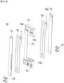
- FIG. 4 is an exploded perspective view showing a contact module for a device for charging and discharging a battery according to an embodiment of the present disclosure.
- the contact module 100 may serve to support the battery cell B and to supply a voltage and current to the battery cell B through coming in contact with both-side electrodes b2 and b3 of the battery cell B.
- the contact module 100 includes contact part copper plates 110 and 150, air pockets 120 and 160, and terminals.
- each of the terminals may be formed on each of the contact part copper plates 110 and 150.
- the contact part copper plates 110 and 150, the air pockets 120 and 160, and the terminals constitute symmetrical pairs.
- the contact part copper plates 110 and 150 and the air pockets 120 and 160, which constitute the pairs, are all able to come in contact with the front and rear surfaces of the both-side electrodes b2 and b3 of the battery cell B disposed between the contact modules 100, and the front and rear surfaces of the both-side electrodes b2 and b3 are able to be simultaneously energized. If the front and rear surfaces of the both-side electrodes b2 and b3 are able to be simultaneously energized, the contact reliability is improved during the voltage and current supply, and thus the test reliability can be heightened more effectively.
- the contact module 100 is configured to include the first contact part copper plate 110 and the second contact part copper plate 150, the first air pocket 120 and the second air pocket 160, and the first terminal and the second terminal.
- the first contact part copper plate 110 and the second contact part copper plate 150 are disposed to be spaced apart from each other.
- the contact module 100 may further include a support body configured to support the first contact part copper plate 110 and the second contact part copper plate 150 which are spaced apart from each other.
- the support body includes an upper end support body 141, a lower end support body 142, and a connection frame 147.
- connection frame 147 may connect the upper end support body 141 and the lower end support body 142 with each other.
- the connection frame 147 may be formed in the shape of a plate.
- the first contact part copper plate 110 and the second contact part copper plate 150 are fixed to the upper end support body 141 and the lower end support body 142 in a manner of being elastically supported.
- an upper end of the first contact part copper plate 110 is fixed to and is elastically supported by an upper end of one side of the upper end support body 141 through the elastic member 145, and a lower end thereof is fixed to and is elastically supported by a lower end of one side of the lower end support body 142 through the elastic member 145.
- an upper end of the second contact part copper plate 150 is fixed to and is elastically supported by an upper end of the other side of the upper end support body 141 through the elastic member 145, and a lower end thereof is fixed to and is elastically supported by a lower end of the other side of the lower end support body 142 through the elastic member 145.
- the elastic member 145 may be a coil spring.
- the first contact part copper plate 110 and the second contact part copper plate 150 may be combined with the upper end support body 141 and the lower end support body 142 in a state where the coil spring is combined with an outer periphery of a bolt, and thus may be able to make an elastic movement for a predetermined distance against the upper end support body 141 and the lower end support body 142.
- the first contact part copper plate 110 may be elastically supported on one side of the upper end support body 141 and the lower end support body 142
- the second contact part copper plate 150 may be elastically supported on the other side of the upper end support body 141 and the lower end support body 142. More specifically, the first contact part copper plate 110 and the second contact part copper plate 150 may move in an outward direction of the contact module 100 of the device for charging and discharging a battery depending on the expansion of the first air pocket 120 and the second air pocket 160.
- the first air pocket 120 is combined with an inner surface of the first contact part copper plate 110
- the second air pocket 160 is combined with an inner surface of the second contact part copper plate 150.
- the first air pocket 120 and the second air pocket 160 expand or contract by a pneumatic pressure, and during expansion, they move the first contact part copper plate 110 and the second contact part copper plate 150 in the outward direction of the contact module 100, whereas during contraction, they return the first contact part copper plate 110 and the second contact part copper plate 150 to their original positions.
- the first air pocket 120 and the second air pocket 160 are respectively provided with air injection parts 121 and 161 for injecting an air. Since the first air pocket 120 and the second air pocket 160 are provided with the air injection parts 121 and 161, the first air pocket 120 and the second air pocket 160 can simultaneously expand.
- first air pocket 120 and the second air pocket 160 is supported by the upper end support body 141, and the other side thereof is supported by the lower end support body 142.
- first contact part copper plate 110 and the second contact part copper plate 150 may be connected to a power supply part to be supplied with a power therefrom.
- the support body is mounted between the first air pocket 120 and the second air pocket 160.
- the support body comes in contact with and supports the first air pocket 120 and the second air pocket 160 being spaced apart from each other.
- the support body of the contact module 100 may be connected to the support member 149.
- guide slots 141a and 142a on facing surfaces of the upper end support body 141 and the lower end support body 142, guide slots 141a and 142a, in which the support members 149 are slidably combined and supported, are formed.
- the guide slots 141a and 142a support edge parts of the support members 149, and stably fix the support members 149 to the upper end support body 141 and the lower end support body 142.
- the contact module 100 includes two air pockets 120 and 160, but the contact module 100 may include only one air pocket according to embodiments.
- one air pocket may come in contact with two contact part copper plates 110 and 150, and as the one air pocket expands, two contact part copper plates 110 and 150 may move in opposite directions.
- the support body may be configured to support two contact part copper plates 110 and 150, and the support body may include an accommodation groove in which one air pocket is accommodated.
- the pressurization plates 291 and 292 pressurize the contact members in a direction in which the contact members get closer to each other. Accordingly, the cell body b1 of the battery cell B may be pressurized by the pressurization members adjacently disposed, and the distance between the electrodes b2 and b3 of the battery cell B and the adjacent contact module 100 gets closer.
- the distance between the first contact part copper plate 110 and the second contact part copper plate 150, which face each other, of the adjacent contact modules 100 may get closer.
- the contact part copper plates 110 and 150 facing each other may elastically move by the pressurization thereof, and thus the distance may get further closer. Accordingly, the distance between the electrodes b2 and b3 of the battery cell B and the contact part copper plates 110 and 150 of the adjacent contact modules 100 may also get further closer.
- the first air pocket 120 and the second air pocket 160 may simultaneously expand, and the contact part copper plates 110 and 150 may come in contact with the electrodes b2 and b3 of the battery cell B.
- the contact part copper plates 110 and 150 can come in contact with the electrodes b2 and b3 of the battery cell B through the air pockets 120 and 160, and thus the electrodes b2 and b3 of the battery cell B can be prevented from being damaged.
- FIG. 5 is a cross-sectional view taken along line a-a of FIG. 3 and is a view showing a shape in which electrodes of a battery cell are positioned on contact modules of a device for charging and discharging a battery according to an embodiment of the present disclosure.
- FIG. 6 is a view showing a shape in which a first air pocket and a second air pocket expand after a contact module for a device for charging and discharging a battery according to an embodiment of the present disclosure is pressed by a pressurization plate.
- FIG. 6 is a view showing a shape in which a first air pocket and a second air pocket expand after a contact module for a device for charging and discharging a battery according to an embodiment of the present disclosure is pressed by a pressurization plate.
- FIG. 7 is a view explaining the principle in which a first contact part copper plate and a second contact part copper plate move in a direction in which they get closer to each other when a contact module for a device for charging and discharging a battery according to an embodiment of the present disclosure is pressed by a pressurization plate.
- a method for operating a contact module of a device for charging and discharging a battery includes: (a) positioning an electrode b3 of a battery cell B in a space between contact modules 100 and contact modules 100' disposed adjacent to each other; (b) moving the contact modules 100 disposed side by side in a direction in which the contact modules 100 get closer to each other by pressurizing contact members including the contact modules 100 and 100' through a first pressurization plate 291 and a second pressurization plate 292; (c) expanding a first air pocket 120 and a second air pocket 160 combined with inner surfaces of a first contact part copper plate 110 and a second contact part copper plate 150 by supplying an air thereto; and (d) proceeding with a charging/discharging process by making the electrode b3 of the battery cell B, which is positioned between the first contact part copper plate 110 and the second contact part copper plate 150, come in contact with the first contact part copper plate 110 and the second contact part copper plate 150
- the electrode b3 of the battery cell B may be positioned in the space between the contact modules 100 and the contact modules 100' disposed adjacent to each other. Meanwhile, before the electrode b3 of the battery cell B is positioned, the contact members may be formed by combining the support member 149 with the contact modules 100. For example, the guide slots 141a and 142a formed on facing surfaces of an upper end support body 141 and a lower end support body 142 may be combined with the support member 149.
- the first pressurization plate 291 and the second pressurization plate 292 pressurize the contact modules 100 and 100' of the device for charging and discharging a battery in a direction in which the contact modules 100 and 100' get closer, and thus the first contact part copper plate 110 and the second contact part copper plate 150 move in a direction in which they get closer.
- the first contact part copper plate 110 and the second contact part copper plate 150 move in a direction in which they get closer.
- first contact part copper plate 110 and the second contact part copper plate 150 may be combined with the upper end support body 141 and the lower end support body 142 in a state where a coil spring s is combined with an outer periphery of a bolt m, and thus may be able to make an elastic movement for a predetermined distance in an outward direction of the upper end support body 141 and the lower end support body 142.
- the first air pocket 120 and the second air pocket 160 expand through injection of the air into an air injection part 121 of the first air pocket 120 and an air injection part 161 of the second air pocket 160. That is, in the step of expanding the first air pocket 120 and the second air pocket 160, the contact part copper plates 110 and 150 come in contact with the electrode b3 of the battery cell B with the expansion of the first air pocket 120 and the second air pocket 160.
- the air pockets 120 and 160 may simultaneously expand to make the contact part copper plates 110 and 150 simultaneously come in contact with the electrode b3 of the battery cell B, but embodiments of the present disclosure are not limited thereto.
- the first air pocket 120 and the second air pocket 160 may move the first contact part copper plate 110 and the second contact part copper plate 150 in an outward direction of the contact modules 100, and the first contact part copper plate 110 and the second contact part copper plate 150 may come in contact with the electrode of the battery cell B.
- step (d) as the first contact part copper plate 110 and the second contact part copper plate 150 come in contact with the electrode b3 of the battery cell B, the charging/discharging process is performed.
- the step (d) of proceeding with the charging/discharging process may be performed in a state where a power being supplied to the first contact part copper plate 110 is supplied to the contacted electrode of the battery cell B.
- the method may further include contracting the first air pocket 120 and the second air pocket 160 by exhausting the air in the first air pocket 120 and the second air pocket 160.
- contracting the first air pocket 120 and the second air pocket 160 the first contact part copper plate 110 and the second contact part copper plate 150 return to their original positions by their elastic forces, and thus the battery cell B may be separable from the first contact part copper plate 110 and the second contact part copper plate 150.
- the contact module 100 of the device for charging and discharging a battery may be provided with the air pockets 120 and 160 inside the contact part copper plates 110 and 150 that come in contact with the electrodes b2 and b3 of the battery cell B, and the distance between the contact part copper plates 110 and 150 and the electrodes b2 and b3 gets closer by the pressurization operation of the pressurization plates 291 and 292. Thereafter, the first air pocket 120 and the second air pocket 160 combined with the insides of the contact part copper plates 110 and 150 expand, and the first contact part copper plate 110 and the second contact part copper plate 150 come in contact with the electrodes b2 and b3 of the battery cell B.
- the contact module 100 of the device for charging and discharging a battery as described above can pressurize a plurality of pouch-type batteries with the same pressure during a test for charging and discharging the batteries. Further, it is possible to heighten contact reliability of the contact module for the batteries even in case that the batteries have thickness deviations.
- the contact module 100 of the device for charging and discharging a battery can heighten the contact reliability by adjusting the expansion degree of the first air pocket 120 and the second air pocket 160 even in case that the thicknesses of the electrodes b2 and b3 of the battery cell B are changed.
- the contact module 100 and the electrodes b2 and b3 of the battery cell B do not directly come in contact with each other by the pressurizing force of the pressurization plates of the device 10 for charging and discharging a battery, there is no risk of breakage or damage of the contact part copper plates of the contact modules on which the battery cell B is not disposed even in case that the battery cell is not disposed between some of the plurality of contact modules 100. That is, even without positioning of unnecessary dummy cells in a part where the battery cell B is not disposed, the battery charging/discharging test for some battery cells B can be performed more simply.
- the contact module 100 can easily perform the contact part position adjustment during the battery charging/discharging by using the adjustment bars 210 and 220.
Landscapes
- Chemical & Material Sciences (AREA)
- Chemical Kinetics & Catalysis (AREA)
- Electrochemistry (AREA)
- General Chemical & Material Sciences (AREA)
- Engineering & Computer Science (AREA)
- Manufacturing & Machinery (AREA)
- Power Engineering (AREA)
- Battery Mounting, Suspending (AREA)
Abstract
A contact module of a device for charging and discharging a battery is disclosed. The contact module includes: a first contact part copper plate and a second contact part copper plate disposed to be spaced apart from each other; a first air pocket and a second air pocket combined with inner side surfaces of the first contact part copper plate and the second contact part copper plate, respectively, and configured to expand or contract by a pneumatic pressure; and a support body disposed between the first air pocket and the second air pocket and configured to support the first air pocket and the second air pocket being spaced apart from each other.
Description
- The present disclosure relates to a contact module of a device for charging and discharging a battery and a device for charging and discharging a battery including the same, and more particularly to a contact module of a device for charging and discharging a battery, which is able to come in contact with electrodes provided in a battery, and a device for charging and discharging a battery including the same.
- In general, demand for secondary batteries is growing rapidly as power supplies for portable electronic devices for information communication, such as a cellular phone, a tablet PC, a laptop computer, and the like, an electric bicycle, and an electric car.
- A process of manufacturing a secondary battery may be briefly classified into a pole plate process, an assembly process, an activation process, and a test process. The activation process means a process for activating an assembled battery (or battery cell) to be able to use the same. Specifically, during the activation process, a voltage and current are supplied to the battery to charge or discharge the battery. For example, after a contact module of a device for charging and discharging a battery, which is provided with a terminal, comes in contact with an electrode of the battery, the current or voltage is supplied to the electrode provided on the battery through the contact module.
- Meanwhile, in case of a pouch-type battery, the battery may be charged or discharged in a state where the battery is pressed. In this case, since a pressurization plate provided in the battery charging and discharging device presses the contact module, the battery disposed between the contact modules is pressed, and further the electrode of the battery comes in contact with the contact module. In the related art, electrodes of pouch-type batteries and contact modules come in contact with each other in a manner that a plurality of contact modules are disposed side by side, the pouch-type batteries are also disposed between the plurality of contact modules, and pressurization plates simultaneously pressurize the plurality of contact modules.
- However, in case of making the batteries and the contact modules come in contact with each other only by the pressurization plates as above, there is a problem in that it is difficult to pressurize several batteries with the same pressure, and thus contact reliability is degraded. Further, a charging/discharging test is possible only with respect to the pouch-type batteries having the same thickness for uniform transfer of the pressure, whereas with respect to the pouch-type batteries having different thicknesses, the pressure is transferred disproportionately to cause the damage of the electrodes of the batteries or the contact modules. As an alternative to this, springs are provided in the contact modules to heighten the contact performance between the contact modules and the electrodes of the batteries, but the elastic restoring force of the spring becomes lowered through the usage thereof over a predetermined period of time, and thus it is difficult to perform the function of the spring. A solution is needed for this.
- Further, in the related art as described above, since the batteries should be disposed between the respective contact modules without exception, and a dummy cell should be disposed between the contact modules on which the battery is not disposed, there is a problem in that the charging/discharging work is cumbersome.
- The matters described in the above background technology are to help understanding of the background of the present disclosure, and may include the matters that are not the disclosed technology in the related art.
- An object of the present disclosure is to provide a contact module of a device for charging and discharging a battery, and a device for charging and discharging a battery including the same, which can pressurize a plurality of pouch-type batteries with the same pressure during a test for charging and discharging the batteries, facilitate adjustment of contact part positions and make their individual operations possible during battery charging and discharging so as to be able to heighten the contact reliability of contact modules for the batteries even in case that the batteries have thickness deviations.
- According to an embodiment of the present disclosure for achieving the above object, a contact module of a device for charging and discharging a battery includes: a first contact part copper plate and a second contact part copper plate disposed to be spaced apart from each other; a first air pocket and a second air pocket combined with inner side surfaces of the first contact part copper plate and the second contact part copper plate, respectively, and configured to expand or contract by a pneumatic pressure; and a support body disposed between the first air pocket and the second air pocket, and configured to support the first air pocket and the second air pocket being spaced apart from each other.
- According to embodiments of the present disclosure for achieving the above object, a device for charging and discharging a battery includes: a pair of support frames disposed to face each other; an adjustment bar connected to the pair of support frames; and a plurality of contact members connected to the adjustment bar, and disposed side by side to be spaced apart from each other and to be movable, wherein each of the plurality of contact members includes a contact module including: a first contact part copper plate and a second contact part copper plate disposed to be spaced apart from each other; an air pocket combined with inner side surfaces of the first contact part copper plate and the second contact part copper plate, and configured to expand or contract by a pneumatic pressure; and a support body configured to support the first contact part copper plate and the second contact part copper plate being spaced apart from each other.
- The present disclosure has a structure in which pressurization plates first pressurize contact part copper plates, and then two air pockets combined on the insides of the contact part copper plates expand simultaneously to make the contact part copper plates come in contact with electrodes of battery cells simultaneously. Accordingly, the present disclosure has effects of being able to pressurize a plurality of pouch-type battery cells with the same pressure during a test for charging and discharging the battery cells, and being able to heighten contact reliability of contact modules for the electrodes of the battery cells even in case that the battery cells have thickness deviations.
- Further, the present disclosure can heighten the contact reliability between the contact part copper plates and the electrodes of the battery cells by adjusting the expansion degree of the two air pockets even in case that the thicknesses of the electrodes of the battery cells are changed. Further, since the air pockets perform buffering even in case that the battery cells are disposed between only some of the plurality of contact modules without being disposed between all of the plurality of contact modules, the present disclosure has effects of no risk of breakage of the contact part copper plates by the pressurizing force and no damage occurrence.
-
-
FIG. 1 is a front view showing a shape in which both sides of a battery cell are positioned on a contact module of a device for charging and discharging a battery according to an embodiment of the present disclosure. -
FIG. 2 is a side view of a device for charging and discharging a battery including contact modules according to an embodiment of the present disclosure. -
FIG. 3 is a perspective view showing a contact module for a device for charging and discharging a battery according to an embodiment of the present disclosure, andFIG. 4 is an exploded perspective view showing a contact module for a device for charging and discharging a battery according to an embodiment of the present disclosure. -
FIG. 5 is a cross-sectional view taken along line a-a ofFIG. 3 and is a view showing a shape in which electrodes of a battery cell are positioned on contact modules of a device for charging and discharging a battery according to an embodiment of the present disclosure. -
FIG. 6 is a view showing a shape in which a first air pocket and a second air pocket expand after a contact module for a device for charging and discharging a battery according to an embodiment of the present disclosure is pressed by a pressurization plate. -
FIG. 7 is a view explaining the principle in which a first contact part copper plate and a second contact part copper plate move in a direction in which they get closer to each other when a contact module for a device for charging and discharging a battery according to an embodiment of the present disclosure is pressed by a pressurization plate. - Hereinafter, preferred embodiments of the present disclosure will be described in detail with reference to the accompanying drawings.
-
FIG. 1 is a front view showing a shape in which both sides of a battery cell are positioned on a contact module of a device for charging and discharging a battery according to an embodiment of the present disclosure.FIG. 2 illustrates a side surface of a device for charging and discharging a battery including contact modules according to an embodiment of the present disclosure. - As illustrated in
FIGS. 1 and2 , adevice 10 for charging and discharging a battery includes a contact module (hereinafter, "contact module") 100 of a device for charging and discharging a battery, which comes in contact with an electrode of a battery cell B and transfers a voltage and current thereto. - One surface of the
contact module 100 according to embodiments of the present disclosure may come in contact with one surface of the electrode of one battery cell B, and the other surface of thecontact module 100 may come in contact with one surface of the electrode of another battery cell. That is, two contact modules according to embodiments of the present disclosure may be positioned with the electrode of one battery cell B interposed therebetween. For example, thedevice 10 for charging and discharging a battery may include a plurality ofcontact modules 100 so as to be able to perform a test for charging and discharging a battery for a plurality of battery cells B at a time. - The battery cell B may be provided with electrodes b2 and b3 on both side surfaces of the battery cell B, and the
device 10 for charging and discharging a battery may further include asupport member 149 for connecting a pair ofcontact modules 100 corresponding to the electrodes b2 and b3 on both side surfaces of the battery cell B with each other. Thesupport member 149 may be combined with thecontact module 100 corresponding to one side terminal b2 of the battery cell B and thecontact module 100 corresponding to the other side terminal b3 of the battery cell B, and may support the cell body b1 of the battery cell B. - The
device 10 for charging and discharging a battery according to embodiments of the present disclosure may include a pair ofcontact modules 100 and a plurality of contact members including onesupport member 149 connected therewith, and the plurality of contact members may be disposed side by side at regular intervals. - The
device 10 for charging and discharging a battery may includeadjustment bars contact module 100,gear shafts adjustment handles support frames pressurization members - The
adjustment bars contact modules 100. According to embodiments, theadjustment bars support member 149 by penetrating an opening formed on thesupport member 149 connected to the pair ofcontact modules 100. The opening of thesupport member 149 may be provided on an outside of thecontact module 100, and thus theadjustment bars contact module 100. - The
support member 149 may move before and after an extension direction of theadjustment bars adjustment bars - According to embodiments, one end and the other end of the
adjustment bars gear shafts gear shafts adjustment bars gear shafts adjustment handles adjustment bars - The
respective gear shafts first support frame 270 is installed on the side where the one end of theadjustment bars second support frame 280 is installed on the side where the other end of theadjustment bars contact modules 100 positioned to correspond to one-side electrode and the other-side electrode of the battery cell B with therespective adjustment bars - The battery cell B may be of a cylindrical, prismatic, polymer, or pouch type, and in an embodiment, a pouch-type battery cell is exemplified. The charging/discharging test may be to variously evaluate output current and voltage specifications and cycle lifetime of the battery cell B that is used in an electric car. The battery cell B may be used as a portable power charge (PPC) in the electric car. The pouch-type battery cell B includes a cell body b1 and electrodes b2 and b3 on both sides of the cell body b1, and a silicone pad may be disposed on an outer surface of the cell body b1 to protect the cell.
- Each of the battery cells B may be disposed between the
contact modules 100. According to embodiments, one battery cell B may be disposed between twocontact modules 100 along the extension direction of theadjustment bars contact modules 100 and the battery cells B may be extendedly disposed along the extension direction of theadjustment bars contact module 100, the battery cell B, and thecontact module 100. - The
pressurization plates contact modules 100 and thesupport member 149 in a direction in which they get closer to each other. - According to embodiments, the
pressurization plates first pressurization plate 291 and thesecond pressurization plate 292, and thefirst pressurization plate 291 may be disposed in front of the contact member positioned at the forefront in the extension direction of theadjustment bars second pressurization plate 292 may be disposed in the rear of the contact member positioned at the rearmost in the extension direction of theadjustment bars pressurization plates - The
pressurization plates pressurization plates - As the contact members are pressurized in the direction in which they get closer to each other, the battery cell B positioned between the contact members are also pressurized by the contact members. Specifically, the cell body b1 of the battery cell B may be pressurized by the adjacently disposed pressurization members, and the distance between the electrodes b2 and b3 of the battery cell B and the
adjacent contact module 100 also becomes closer. - According to embodiments, a heat dissipation plate may be additionally provided on the surface of the
support member 149 of the contact member. After the cell body b1 of the battery cell is pressurized by thesupport member 149, the heat dissipation plate may transfer heat energy to the pressurized cell body b1 of the battery cell B. The temperature of the heat dissipation plate may be increased, and thus the temperature of the battery cell may also be increased. -
FIG. 3 is a perspective view showing a contact module for a device for charging and discharging a battery according to an embodiment of the present disclosure, andFIG. 4 is an exploded perspective view showing a contact module for a device for charging and discharging a battery according to an embodiment of the present disclosure. - As illustrated in
FIGS. 3 and4 , thecontact module 100 according to an embodiment of the present disclosure may serve to support the battery cell B and to supply a voltage and current to the battery cell B through coming in contact with both-side electrodes b2 and b3 of the battery cell B. - The
contact module 100 includes contactpart copper plates air pockets part copper plates part copper plates air pockets part copper plates air pockets contact modules 100, and the front and rear surfaces of the both-side electrodes b2 and b3 are able to be simultaneously energized. If the front and rear surfaces of the both-side electrodes b2 and b3 are able to be simultaneously energized, the contact reliability is improved during the voltage and current supply, and thus the test reliability can be heightened more effectively. - Specifically, the
contact module 100 is configured to include the first contactpart copper plate 110 and the second contactpart copper plate 150, thefirst air pocket 120 and thesecond air pocket 160, and the first terminal and the second terminal. The first contactpart copper plate 110 and the second contactpart copper plate 150 are disposed to be spaced apart from each other. - The
contact module 100 may further include a support body configured to support the first contactpart copper plate 110 and the second contactpart copper plate 150 which are spaced apart from each other. The support body includes an upperend support body 141, a lowerend support body 142, and aconnection frame 147. - Upper ends of the first contact
part copper plate 110 and the second contactpart copper plate 150 are fixed to the upperend support body 141, and lower ends of the contactpart copper plate 110 and the second contactpart copper plate 150 are fixed to the lowerend support body 142. In an embodiment, each of the upperend support body 141 and the lowerend support body 142 has an external appearance formed in the shape of a hexahedron. Theconnection frame 147 may connect the upperend support body 141 and the lowerend support body 142 with each other. For example, theconnection frame 147 may be formed in the shape of a plate. The first contactpart copper plate 110 and the second contactpart copper plate 150 are fixed to the upperend support body 141 and the lowerend support body 142 in a manner of being elastically supported. Specifically, an upper end of the first contactpart copper plate 110 is fixed to and is elastically supported by an upper end of one side of the upperend support body 141 through theelastic member 145, and a lower end thereof is fixed to and is elastically supported by a lower end of one side of the lowerend support body 142 through theelastic member 145. Further, an upper end of the second contactpart copper plate 150 is fixed to and is elastically supported by an upper end of the other side of the upperend support body 141 through theelastic member 145, and a lower end thereof is fixed to and is elastically supported by a lower end of the other side of the lowerend support body 142 through theelastic member 145. - The
elastic member 145 may be a coil spring. As an example, the first contactpart copper plate 110 and the second contactpart copper plate 150 may be combined with the upperend support body 141 and the lowerend support body 142 in a state where the coil spring is combined with an outer periphery of a bolt, and thus may be able to make an elastic movement for a predetermined distance against the upperend support body 141 and the lowerend support body 142. - By the above-described configuration, the first contact
part copper plate 110 may be elastically supported on one side of the upperend support body 141 and the lowerend support body 142, and the second contactpart copper plate 150 may be elastically supported on the other side of the upperend support body 141 and the lowerend support body 142. More specifically, the first contactpart copper plate 110 and the second contactpart copper plate 150 may move in an outward direction of thecontact module 100 of the device for charging and discharging a battery depending on the expansion of thefirst air pocket 120 and thesecond air pocket 160. - The
first air pocket 120 is combined with an inner surface of the first contactpart copper plate 110, and thesecond air pocket 160 is combined with an inner surface of the second contactpart copper plate 150. Thefirst air pocket 120 and thesecond air pocket 160 expand or contract by a pneumatic pressure, and during expansion, they move the first contactpart copper plate 110 and the second contactpart copper plate 150 in the outward direction of thecontact module 100, whereas during contraction, they return the first contactpart copper plate 110 and the second contactpart copper plate 150 to their original positions. - The
first air pocket 120 and thesecond air pocket 160 are respectively provided withair injection parts first air pocket 120 and thesecond air pocket 160 are provided with theair injection parts first air pocket 120 and thesecond air pocket 160 can simultaneously expand. - One side of the
first air pocket 120 and thesecond air pocket 160 is supported by the upperend support body 141, and the other side thereof is supported by the lowerend support body 142. Although not illustrated, the first contactpart copper plate 110 and the second contactpart copper plate 150 may be connected to a power supply part to be supplied with a power therefrom. - The support body is mounted between the
first air pocket 120 and thesecond air pocket 160. The support body comes in contact with and supports thefirst air pocket 120 and thesecond air pocket 160 being spaced apart from each other. According to embodiments, the support body of thecontact module 100 may be connected to thesupport member 149. For this, on facing surfaces of the upperend support body 141 and the lowerend support body 142,guide slots support members 149 are slidably combined and supported, are formed. Theguide slots support members 149, and stably fix thesupport members 149 to the upperend support body 141 and the lowerend support body 142. - In the description, explanation has been made on the assumption that the
contact module 100 includes twoair pockets contact module 100 may include only one air pocket according to embodiments. In this case, one air pocket may come in contact with two contactpart copper plates part copper plates part copper plates - According to embodiments of the present disclosure, the
pressurization plates adjacent contact module 100 gets closer. - Specifically, with the pressurization of the
pressurization plates part copper plate 110 and the second contactpart copper plate 150, which face each other, of theadjacent contact modules 100 may get closer. Further, according to embodiments, the contactpart copper plates part copper plates adjacent contact modules 100 may also get further closer. - Thereafter, in a state where the distance between the electrodes b2 and b3 of the battery cell B and the contact
part copper plates first air pocket 120 and thesecond air pocket 160 may simultaneously expand, and the contactpart copper plates - That is, even without strong pressurization by the
pressurization plates part copper plates air pockets -
FIG. 5 is a cross-sectional view taken along line a-a ofFIG. 3 and is a view showing a shape in which electrodes of a battery cell are positioned on contact modules of a device for charging and discharging a battery according to an embodiment of the present disclosure.FIG. 6 is a view showing a shape in which a first air pocket and a second air pocket expand after a contact module for a device for charging and discharging a battery according to an embodiment of the present disclosure is pressed by a pressurization plate.FIG. 7 is a view explaining the principle in which a first contact part copper plate and a second contact part copper plate move in a direction in which they get closer to each other when a contact module for a device for charging and discharging a battery according to an embodiment of the present disclosure is pressed by a pressurization plate. - Referring to
FIGS. 5 to 7 , a method for operating a contact module of a device for charging and discharging a battery according to an embodiment of the present disclosure includes: (a) positioning an electrode b3 of a battery cell B in a space between contact modules 100 and contact modules 100' disposed adjacent to each other; (b) moving the contact modules 100 disposed side by side in a direction in which the contact modules 100 get closer to each other by pressurizing contact members including the contact modules 100 and 100' through a first pressurization plate 291 and a second pressurization plate 292; (c) expanding a first air pocket 120 and a second air pocket 160 combined with inner surfaces of a first contact part copper plate 110 and a second contact part copper plate 150 by supplying an air thereto; and (d) proceeding with a charging/discharging process by making the electrode b3 of the battery cell B, which is positioned between the first contact part copper plate 110 and the second contact part copper plate 150, come in contact with the first contact part copper plate 110 and the second contact part copper plate 150 by moving the first contact part copper plate 110 and the second contact part copper plate 150 in an outward direction of the contact modules 100 and 100' through expansion of the first air pocket 120 and the second air pocket 160. - Referring to
FIG. 5 , in step (a), the electrode b3 of the battery cell B may be positioned in the space between thecontact modules 100 and the contact modules 100' disposed adjacent to each other. Meanwhile, before the electrode b3 of the battery cell B is positioned, the contact members may be formed by combining thesupport member 149 with thecontact modules 100. For example, theguide slots end support body 141 and a lowerend support body 142 may be combined with thesupport member 149. - In steps (b) and (c), the
first pressurization plate 291 and thesecond pressurization plate 292 pressurize thecontact modules 100 and 100' of the device for charging and discharging a battery in a direction in which thecontact modules 100 and 100' get closer, and thus the first contactpart copper plate 110 and the second contactpart copper plate 150 move in a direction in which they get closer. In this case, as illustrated inFIG. 7 , since the first contactpart copper plate 110 and the second contactpart copper plate 150 may be combined with the upperend support body 141 and the lowerend support body 142 in a state where a coil spring s is combined with an outer periphery of a bolt m, and thus may be able to make an elastic movement for a predetermined distance in an outward direction of the upperend support body 141 and the lowerend support body 142. - As illustrated in
FIG. 6 , in steps (c) and (d), thefirst air pocket 120 and thesecond air pocket 160 expand through injection of the air into anair injection part 121 of thefirst air pocket 120 and anair injection part 161 of thesecond air pocket 160. That is, in the step of expanding thefirst air pocket 120 and thesecond air pocket 160, the contactpart copper plates first air pocket 120 and thesecond air pocket 160. For example, theair pockets part copper plates - In case that the
first air pocket 120 and thesecond air pocket 160 expand, thefirst air pocket 120 and thesecond air pocket 160 may move the first contactpart copper plate 110 and the second contactpart copper plate 150 in an outward direction of thecontact modules 100, and the first contactpart copper plate 110 and the second contactpart copper plate 150 may come in contact with the electrode of the battery cell B. - In step (d), as the first contact
part copper plate 110 and the second contactpart copper plate 150 come in contact with the electrode b3 of the battery cell B, the charging/discharging process is performed. - The step (d) of proceeding with the charging/discharging process may be performed in a state where a power being supplied to the first contact
part copper plate 110 is supplied to the contacted electrode of the battery cell B. - The method may further include contracting the
first air pocket 120 and thesecond air pocket 160 by exhausting the air in thefirst air pocket 120 and thesecond air pocket 160. By contracting thefirst air pocket 120 and thesecond air pocket 160, the first contactpart copper plate 110 and the second contactpart copper plate 150 return to their original positions by their elastic forces, and thus the battery cell B may be separable from the first contactpart copper plate 110 and the second contactpart copper plate 150. - As described above, the
contact module 100 of the device for charging and discharging a battery may be provided with theair pockets part copper plates part copper plates pressurization plates first air pocket 120 and thesecond air pocket 160 combined with the insides of the contactpart copper plates part copper plate 110 and the second contactpart copper plate 150 come in contact with the electrodes b2 and b3 of the battery cell B. - Accordingly, the
contact module 100 of the device for charging and discharging a battery as described above can pressurize a plurality of pouch-type batteries with the same pressure during a test for charging and discharging the batteries. Further, it is possible to heighten contact reliability of the contact module for the batteries even in case that the batteries have thickness deviations. - Further, the
contact module 100 of the device for charging and discharging a battery can heighten the contact reliability by adjusting the expansion degree of thefirst air pocket 120 and thesecond air pocket 160 even in case that the thicknesses of the electrodes b2 and b3 of the battery cell B are changed. - Further, since the
contact module 100 and the electrodes b2 and b3 of the battery cell B do not directly come in contact with each other by the pressurizing force of the pressurization plates of thedevice 10 for charging and discharging a battery, there is no risk of breakage or damage of the contact part copper plates of the contact modules on which the battery cell B is not disposed even in case that the battery cell is not disposed between some of the plurality ofcontact modules 100. That is, even without positioning of unnecessary dummy cells in a part where the battery cell B is not disposed, the battery charging/discharging test for some battery cells B can be performed more simply. - Further, the
contact module 100 can easily perform the contact part position adjustment during the battery charging/discharging by using the adjustment bars 210 and 220. - The above explanation of the present disclosure is merely for exemplary explanation of the technical idea of the present disclosure, and it can be understood by those of ordinary skill in the art to which the present disclosure pertains that various corrections and modifications thereof will be possible in a range that does not deviate from the essential characteristics of the present disclosure. Accordingly, it should be understood that the embodiments disclosed in the present disclosure are not to limit the technical idea of the present disclosure, but to explain the same, and thus the scope of the technical idea of the present disclosure is not limited by such embodiments. The scope of the present disclosure should be interpreted by the appended claims to be described later, and all technical ideas in the equivalent range should be interpreted as being included in the scope of the present disclosure.
Claims (6)
- A contact module of a device for charging and discharging a battery comprising:a first contact part copper plate and a second contact part copper plate disposed to be spaced apart from each other;a first air pocket and a second air pocket combined with inner side surfaces of the first contact part copper plate and the second contact part copper plate, respectively, and configured to expand or contract by a pneumatic pressure; anda support body disposed between the first air pocket and the second air pocket, and configured to support the first air pocket and the second air pocket being spaced apart from each other.
- The contact module of claim 1, wherein the first contact part copper plate and the second contact part copper plate are configured to move depending on expansion of the first air pocket and the second air pocket.
- The contact module of claim 1, wherein each of the first air pocket and the second air pocket is provided with an air injection part configured to inject an air.
- The contact module of claim 1, wherein the support body comprises an upper end support body and a lower end support body configured to support the first contact part copper plate and the second contact part copper plate being spaced apart from each other.
- The contact module of claim 4, wherein an upper end and a lower end of the first contact part copper plate are fixed to and are elastically supported by a one-side upper end of the upper end support body and a one-side lower end of the lower end support body through an elastic member, and
wherein an upper end and a lower end of the second contact part copper plate are fixed to and are elastically supported by the other-side upper end of the upper end support body and the other-side lower end of the lower end support body through an elastic member. - The contact module of claim 4, wherein a guide slot is formed on a surface on which the upper end support body and the lower end support body face each other.
Applications Claiming Priority (1)
| Application Number | Priority Date | Filing Date | Title |
|---|---|---|---|
| KR1020220095805A KR20240018043A (en) | 2022-08-02 | 2022-08-02 | Contact module of device for charging and discharging the battery and the device including the same |
Publications (1)
| Publication Number | Publication Date |
|---|---|
| EP4318698A1 true EP4318698A1 (en) | 2024-02-07 |
Family
ID=87429700
Family Applications (1)
| Application Number | Title | Priority Date | Filing Date |
|---|---|---|---|
| EP23186770.6A Pending EP4318698A1 (en) | 2022-08-02 | 2023-07-20 | Contact module of device for charging and discharging the battery and the device including the same |
Country Status (3)
| Country | Link |
|---|---|
| US (1) | US20240047839A1 (en) |
| EP (1) | EP4318698A1 (en) |
| KR (1) | KR20240018043A (en) |
Citations (4)
| Publication number | Priority date | Publication date | Assignee | Title |
|---|---|---|---|---|
| KR20130102707A (en) * | 2012-03-08 | 2013-09-23 | 주식회사 엘지화학 | Battery cell charge-discharge device with novel structure |
| CN103811817A (en) * | 2014-02-12 | 2014-05-21 | 宁德新能源科技有限公司 | Lithium ion battery hot-press formation clamp |
| WO2022119198A1 (en) * | 2020-12-01 | 2022-06-09 | 주식회사 엘지에너지솔루션 | Device for charging/discharging battery cell and method for charging/discharging battery cell by using same |
| KR20220086082A (en) * | 2020-12-16 | 2022-06-23 | 주식회사 원익피앤이 | Secondary battery charging and discharging unit and formation system using the same |
-
2022
- 2022-08-02 KR KR1020220095805A patent/KR20240018043A/en unknown
-
2023
- 2023-07-20 EP EP23186770.6A patent/EP4318698A1/en active Pending
- 2023-07-31 US US18/228,578 patent/US20240047839A1/en active Pending
Patent Citations (4)
| Publication number | Priority date | Publication date | Assignee | Title |
|---|---|---|---|---|
| KR20130102707A (en) * | 2012-03-08 | 2013-09-23 | 주식회사 엘지화학 | Battery cell charge-discharge device with novel structure |
| CN103811817A (en) * | 2014-02-12 | 2014-05-21 | 宁德新能源科技有限公司 | Lithium ion battery hot-press formation clamp |
| WO2022119198A1 (en) * | 2020-12-01 | 2022-06-09 | 주식회사 엘지에너지솔루션 | Device for charging/discharging battery cell and method for charging/discharging battery cell by using same |
| KR20220086082A (en) * | 2020-12-16 | 2022-06-23 | 주식회사 원익피앤이 | Secondary battery charging and discharging unit and formation system using the same |
Also Published As
| Publication number | Publication date |
|---|---|
| US20240047839A1 (en) | 2024-02-08 |
| KR20240018043A (en) | 2024-02-13 |
Similar Documents
| Publication | Publication Date | Title |
|---|---|---|
| EP3282515B1 (en) | Battery module, battery pack comprising battery module, and vehicle comprising battery pack | |
| CN101369649B (en) | Battery connecting apparatus | |
| CN104218271A (en) | Battery module | |
| EP1846964B1 (en) | Battery module with battery cartridge-connecting system | |
| KR102317506B1 (en) | Battery pack | |
| KR102101429B1 (en) | Lead welding apparatus, battery module manufactured by the lead welding apparatus and battery pack comprising the battery module | |
| WO2016056846A1 (en) | Battery module having improved safety and operational lifespan | |
| CN101330135A (en) | Battery module | |
| WO2014030910A1 (en) | Battery module assembly and manufacturing method therefor | |
| KR101509206B1 (en) | Secondary battery charge and discharge jig with improved grippre exchange structure | |
| KR20120032742A (en) | Jig for charging and discharging of secondarybattery | |
| CN111433938A (en) | Battery module, battery pack including the same, and vehicle including the battery pack | |
| KR20210126220A (en) | Cell jig comprising multi-stage hydraulic cylinder, battery module and secondary battery evaluation apparatus comprising the same | |
| KR102363196B1 (en) | Gripper for charging and discharging of pouch type battery, and charging and discharging device of pouch type battery having same | |
| EP3624244B1 (en) | Method for activating a battery cell | |
| EP4318698A1 (en) | Contact module of device for charging and discharging the battery and the device including the same | |
| EP3644401B1 (en) | Battery module, and battery pack and vehicle comprising same | |
| KR102050033B1 (en) | High temperature pressing device for battery cell of photovoltaic module | |
| EP4250416A2 (en) | Battery cell pressing module and charge/discharge apparatus for secondary battery having the same | |
| US9468115B2 (en) | Partition board, and method of restraining electrical storage elements | |
| CN201270266Y (en) | Battery connecting apparatus | |
| CN219575902U (en) | Battery cell sealing device | |
| CN220710579U (en) | Battery module and battery module | |
| US20240030480A1 (en) | Pressing apparatus for battery cell | |
| CN215600437U (en) | Explosion-proof small-size lithium cell |
Legal Events
| Date | Code | Title | Description |
|---|---|---|---|
| PUAI | Public reference made under article 153(3) epc to a published international application that has entered the european phase |
Free format text: ORIGINAL CODE: 0009012 |
|
| STAA | Information on the status of an ep patent application or granted ep patent |
Free format text: STATUS: REQUEST FOR EXAMINATION WAS MADE |
|
| 17P | Request for examination filed |
Effective date: 20230720 |
|
| AK | Designated contracting states |
Kind code of ref document: A1 Designated state(s): AL AT BE BG CH CY CZ DE DK EE ES FI FR GB GR HR HU IE IS IT LI LT LU LV MC ME MK MT NL NO PL PT RO RS SE SI SK SM TR |