EP4317000A1 - Plastic bag opening apparatus and opening method - Google Patents
Plastic bag opening apparatus and opening method Download PDFInfo
- Publication number
- EP4317000A1 EP4317000A1 EP22907700.3A EP22907700A EP4317000A1 EP 4317000 A1 EP4317000 A1 EP 4317000A1 EP 22907700 A EP22907700 A EP 22907700A EP 4317000 A1 EP4317000 A1 EP 4317000A1
- Authority
- EP
- European Patent Office
- Prior art keywords
- plastic bag
- inlet
- elevating member
- elevating
- adsorbed
- Prior art date
- Legal status (The legal status is an assumption and is not a legal conclusion. Google has not performed a legal analysis and makes no representation as to the accuracy of the status listed.)
- Granted
Links
Images


Classifications
-
- B—PERFORMING OPERATIONS; TRANSPORTING
- B65—CONVEYING; PACKING; STORING; HANDLING THIN OR FILAMENTARY MATERIAL
- B65B—MACHINES, APPARATUS OR DEVICES FOR, OR METHODS OF, PACKAGING ARTICLES OR MATERIALS; UNPACKING
- B65B43/00—Forming, feeding, opening or setting-up containers or receptacles in association with packaging
- B65B43/12—Feeding flexible bags or carton blanks in flat or collapsed state; Feeding flat bags connected to form a series or chain
- B65B43/14—Feeding individual bags or carton blanks from piles or magazines
- B65B43/16—Feeding individual bags or carton blanks from piles or magazines by grippers
- B65B43/18—Feeding individual bags or carton blanks from piles or magazines by grippers by suction-operated grippers
-
- B—PERFORMING OPERATIONS; TRANSPORTING
- B65—CONVEYING; PACKING; STORING; HANDLING THIN OR FILAMENTARY MATERIAL
- B65B—MACHINES, APPARATUS OR DEVICES FOR, OR METHODS OF, PACKAGING ARTICLES OR MATERIALS; UNPACKING
- B65B43/00—Forming, feeding, opening or setting-up containers or receptacles in association with packaging
- B65B43/26—Opening or distending bags; Opening, erecting, or setting-up boxes, cartons, or carton blanks
- B65B43/28—Opening or distending bags; Opening, erecting, or setting-up boxes, cartons, or carton blanks by grippers co-operating with fixed supports
-
- B—PERFORMING OPERATIONS; TRANSPORTING
- B31—MAKING ARTICLES OF PAPER, CARDBOARD OR MATERIAL WORKED IN A MANNER ANALOGOUS TO PAPER; WORKING PAPER, CARDBOARD OR MATERIAL WORKED IN A MANNER ANALOGOUS TO PAPER
- B31B—MAKING CONTAINERS OF PAPER, CARDBOARD OR MATERIAL WORKED IN A MANNER ANALOGOUS TO PAPER
- B31B70/00—Making flexible containers, e.g. envelopes or bags
- B31B70/003—Opening or distending bags
-
- B—PERFORMING OPERATIONS; TRANSPORTING
- B65—CONVEYING; PACKING; STORING; HANDLING THIN OR FILAMENTARY MATERIAL
- B65B—MACHINES, APPARATUS OR DEVICES FOR, OR METHODS OF, PACKAGING ARTICLES OR MATERIALS; UNPACKING
- B65B43/00—Forming, feeding, opening or setting-up containers or receptacles in association with packaging
- B65B43/26—Opening or distending bags; Opening, erecting, or setting-up boxes, cartons, or carton blanks
- B65B43/30—Opening or distending bags; Opening, erecting, or setting-up boxes, cartons, or carton blanks by grippers engaging opposed walls, e.g. suction-operated
-
- B—PERFORMING OPERATIONS; TRANSPORTING
- B65—CONVEYING; PACKING; STORING; HANDLING THIN OR FILAMENTARY MATERIAL
- B65B—MACHINES, APPARATUS OR DEVICES FOR, OR METHODS OF, PACKAGING ARTICLES OR MATERIALS; UNPACKING
- B65B43/00—Forming, feeding, opening or setting-up containers or receptacles in association with packaging
- B65B43/26—Opening or distending bags; Opening, erecting, or setting-up boxes, cartons, or carton blanks
- B65B43/34—Opening or distending bags; Opening, erecting, or setting-up boxes, cartons, or carton blanks by internal pressure
-
- B—PERFORMING OPERATIONS; TRANSPORTING
- B65—CONVEYING; PACKING; STORING; HANDLING THIN OR FILAMENTARY MATERIAL
- B65B—MACHINES, APPARATUS OR DEVICES FOR, OR METHODS OF, PACKAGING ARTICLES OR MATERIALS; UNPACKING
- B65B43/00—Forming, feeding, opening or setting-up containers or receptacles in association with packaging
- B65B43/26—Opening or distending bags; Opening, erecting, or setting-up boxes, cartons, or carton blanks
- B65B43/34—Opening or distending bags; Opening, erecting, or setting-up boxes, cartons, or carton blanks by internal pressure
- B65B43/36—Opening or distending bags; Opening, erecting, or setting-up boxes, cartons, or carton blanks by internal pressure applied pneumatically
Definitions
- the present disclosure relates to a device and method for opening a plastic bag, which is capable of automatically opening an inlet of the plastic bag.
- the packaging bags may be provided as plastic bags in the form of an envelope, and the plastic bags each have a structure in which surfaces other than one surface are sealed. That is, the non-sealed one surface of the packaging bag serves as an inlet for accommodating the products.
- the plastic bag opening device includes first and second adsorption pads that adsorb two opposite surfaces of the plastic bag, respectively, and a movable member that moves the first and second adsorption pads in directions that are away from each other, to open the inlet of the plastic bag.
- the plastic bag opening device completely opens the inlet of the plastic bag solely by the first and second adsorption pads. That is, the inlet of the plastic bag is difficult to open because of frictional force and static electricity. Accordingly, capacity utilization may be reduced and packaging failure may occur because of a plastic bag opening error.
- An object of the present invention for solving the above problems is to provide a device for opening a plastic bag, which includes an air blower to more easily open an inlet of the plastic bag, and particularly, to completely open the inlet of the plastic bag and accordingly, may increase capacity utilization and prevent an occurrence of defective packaging, and a method for opening a plastic bag using the device.
- the plastic bag opening device may include: an elevating member that lifts the plastic bag in a state in which one surface of the plastic bag is adsorbed; and an air blower that injects air toward the inlet of the plastic bag adsorbed to the elevating member so that the inlet of the plastic bag is opened to be widened.
- the elevating member may include an adsorption pad, which adsorbs the one surface of the plastic bag, and an elevating part that allows the adsorption pad to ascend so as to lift the plastic bag adsorbed to the adsorption pad up to a horizontal line at which the air blower is disposed.
- the air blower may include an injection nozzle, which injects the air toward the inlet of the plastic bag so that the inlet of the plastic bag is opened to be widened, and a frame to which the injection nozzle is coupled.
- an air injection opening may be provided to be inclined downward at a set angle with respect to the horizontal line.
- the set angle may be set to 3° to 10°.
- the injection nozzle may be coupled to the frame so that the angle is adjustable up and down or left and right.
- the plastic bag opening device may further include a rotating member that rotates the elevating member so that the inlet of the plastic bag adsorbed to the elevating member faces upward.
- the plastic bag opening device may further include a finger member provided with a pair of fingers that are inserted into the inlet of the plastic bag adsorbed to the elevating member and pull and expand the inlet of the plastic bag in two opposite directions.
- the plastic bag opening device may further include a movable member that moves the elevating member to be far away from the finger member, so that the inlet of the plastic bag is expanded by an area between the finger member and the elevating member.
- the present invention relates to a plastic bag opening method that opens an inlet of a plastic bag having a pocket shape.
- the plastic bag opening method may include: an elevating process of adsorbing one surface of the plastic bag and then lifting the plastic bag by using an elevating member; and an opening process of opening the inlet of the plastic bag to be widened by using an air blower to inject air toward the inlet of the plastic bag adsorbed to the elevating member so that the air injected from the air blower flows into the plastic bag through the inlet.
- the elevating member may lift the plastic bag up to a horizontal line at which the air blower is disposed.
- the air blower may inject the air toward the inlet of the plastic bag so that the air is injected downward at a set angle with respect to the horizontal line.
- the set angle may be set to 3° to 10°.
- the plastic bag opening method may include a rotating process of rotating the elevating member by using a rotating member so that the inlet of the plastic bag adsorbed to the elevating member is disposed to face upward, when the opening process is completed.
- the plastic bag opening method may include a primarily expanding process of pulling and expanding the inlet of the plastic bag in two opposite directions by inserting a pair of fingers provided in a finger member into the inlet of the plastic bag adsorbed to the elevating member and moving the pair of fingers in directions that are away from each other, when the rotating process is completed.
- the plastic bag opening method may include a secondarily expanding process of expanding the inlet of the plastic bag by an area between the finger member and the elevating member by using a movable member to move the elevating member to be far away from the finger member, when the primarily expanding process is completed.
- the plastic bag opening device may include the air blower to inject the air into the inlet of the plastic bag and completely open the inlet of the plastic bag. Accordingly, the capacity utilization may increase, and the occurrence of the defective packaging may be prevented.
- a plastic bag 10 has a structure in the form of a pocket having one surface in which an inlet 11 is formed.
- the plastic bag 10 having such a structure is kept in a state in which the plastic bag 10 is pressed flat so that one surface 12 and the other surface 13 are in close contact with each other.
- the inlet 11 thereof is opened to store or pack products, etc.
- a plastic bag opening device 1 may automatically open the inlet 11 of the plastic bag 10, and particularly, completely open the inlet of the plastic bag. Accordingly, efficiency of accommodating articles may be improved.
- the plastic bag opening device 1 has a structure that opens the inlet 11 of the plastic bag 10 having a pocket shape. That is, the plastic bag opening device 1 according to the first embodiment of the present invention includes an elevating member 100, which lifts the plastic bag 10 in a state in which one surface 12 (a top surface of the plastic bag in FIG. 1 ) of the plastic bag 10 is adsorbed, and an air blower 200 which injects air toward the inlet 11 of the plastic bag 10 adsorbed to the elevating member 100 so that the inlet 11 of the plastic bag 10 is opened to be widened.
- an elevating member 100 which lifts the plastic bag 10 in a state in which one surface 12 (a top surface of the plastic bag in FIG. 1 ) of the plastic bag 10 is adsorbed
- an air blower 200 which injects air toward the inlet 11 of the plastic bag 10 adsorbed to the elevating member 100 so that the inlet 11 of the plastic bag 10 is opened to be widened.
- the elevating member 100 is intended to lift the plastic bag 10.
- the elevating member 100 includes an adsorption pad 110, which adsorbs the one surface 12 of the plastic bag 10, and an elevating part 120 which allows the adsorption pad 110 to ascend and lifts the plastic bag 10 adsorbed to the adsorption pad 110 up to a horizontal line (0) at which the air blower 200 is disposed.
- the adsorption pad 110 may be provided in plurality so as to lift the entire one surface 12 provided at a side of the inlet 11 of the plastic bag 10, and preferably, five or more adsorption pads 110 may be provided.
- the adsorption pad 110 may have a structure in which an air suction force is used to adsorb the one surface 12 of the plastic bag 10.
- the elevating part 120 may be provided as a hydraulic cylinder or pneumatic cylinder that allows the adsorption pad 110 to ascend or return to an initial position.
- the elevating member 100 having the structure as described above may stably adsorb the one surface 12 of the plastic bag 10 and effectively lift the adsorbed plastic bag 10.
- the air blower 200 is intended to open the inlet of the plastic bag.
- the air blower 200 includes an injection nozzle 210, which injects the air toward the inlet 11 of the plastic bag 10 so that the inlet 11 of the plastic bag 10 is opened to be widened, and a frame 220 to which the injection nozzle 210 is coupled.
- the frame 220 is formed to extend in a direction corresponding to the inlet 11 of the plastic bag 10 (a front and rear direction in FIG. 1 ), and the injection nozzle 210 is provided in plurality at set intervals on one surface of the frame 220, which faces the plastic bag 10.
- the injection nozzle 210 may be provided to face the inlet 11 of the plastic bag 10 so that an air injection opening through which the air is injected is inclined downward at a set angle ⁇ ° with respect to the horizontal line (O).
- the air injected from the injection nozzle 210 may be injected toward the other surface 13 rather than the one surface 12 of the plastic bag 10. Accordingly, the other surface 13 of the plastic bag 10, which adheres to the one surface 12 by static electricity, etc., may be easily separated to open the inlet 11 of the plastic bag 10.
- the set angle ⁇ ° may be set to 3° to 10°, and preferably, may be provided as 5° to 8°.
- an injection angle of the injection nozzle 210 is 3° or less, there is no significant difference compared to the case of injecting toward the horizontal line.
- the injection angle is 10° or greater, the air may be injected outside the inlet 11, and thus the efficiency may be reduced.
- the elevating member 100 lifts the one surface 12 of the plastic bag 10 in the adsorbed state.
- the other surface a bottom surface of the plastic bag in FIG. 1
- the plastic bag 10 may have a portion adhering to the one surface by static electricity.
- the entirety of the other surface 13 may also adhere to the one surface, and the entirety of the other surface 13 may also be separated from the one surface due to the load.
- the air blower 200 is used to inject the air toward the inlet 11 of the plastic bag 10.
- the air injected by the air blower 200 may flow into the inlet 11 to open the inlet 11, and part of the air having flowed into the plastic bag 10 may be discharged through the inlet 11 to reopen the inlet 11.
- the plastic bag opening device 1 includes the elevating member 100 and the air blower 200, the inlet 11 of the plastic bag 10 may be opened to be completely widened.
- the plastic bag opening device 1 may further include a rotating member 300 that rotates the elevating member 100 so that the inlet 11 of the plastic bag 10 faces upward.
- the rotating member 300 includes a rotating body 310, to which the elevating member 100 is rotatably coupled, and a rotating part 320 which rotates the elevating member 100 coupled to the rotating body 310 so that the inlet 11 of the plastic bag 10 adsorbed to the elevating member 100 is disposed to face upward.
- the rotating part 320 may be a driving motor.
- the plastic bag opening device 1 may further include a finger member 400 that pulls the inlet 11 of the plastic bag 10 to primarily expand the inlet 11 of the plastic bag 10 in two opposite directions.
- the finger member 400 includes a pair of fingers 410, and the pair of fingers 410 pulls the inlet 11 of the plastic bag 10 adsorbed to the elevating member 100 in the two opposite directions while moving in directions that are away from each other, in a state inserted into the inlet 11 of the plastic bag 10.
- the finger member 400 includes the pair of fingers 410, which pulls the inlet 11 of the plastic bag 10 adsorbed to the elevating member 100 in the two opposite directions while moving in the directions that are away from each other, in the state inserted into the inlet 11 of the plastic bag 10, a first driving part 420, which allows the pair of fingers 410 to descend toward the plastic bag 10 so that the pair of fingers 410 are inserted into the inlet 11 of the plastic bag 10, and a second driving part 430 which allows the pair of fingers 410 to move in the directions that are away from each other.
- the finger member 400 having such a structure may expand the inlet 11 of the plastic bag 10 in the two opposite directions, and may also prevent the inlet 11 of the plastic bag 10 from sagging.
- the plastic bag opening device 1 may further include a movable member 500 for secondarily expanding the inlet 11 of the plastic bag 10.
- the movable member 500 moves the elevating member 100 to be far away from the finger member 400 so that the inlet 11 of the plastic bag 10 is secondarily expanded by an area between the finger member 400 and the elevating member 100.
- the one surface 12 of the plastic bag is adsorbed to the elevating member 100, and the other surface 13 of the plastic bag 10 is supported by the finger member 400.
- the inlet 11 of the plastic bag 10 may be expanded while the one surface 12 of the plastic bag 10 moves together with the elevating member 100.
- a plastic bag opening method includes an elevating process, an opening process, a rotating process, a primarily expanding process, and a secondarily expanding process in order that an inlet 11 of a plastic bag 10 having a pocket shape is opened to be widened.
- the plastic bag opening method according to the first embodiment of present invention uses the plastic bag opening device according to the first embodiment of the present invention described above, and the plastic bag opening device 1 according to the first embodiment of the present invention includes an elevating member 100, an air blower 200, a rotating member 300, a finger member 400, and a movable member 500.
- the elevating member 100 is used to adsorb one surface 12 (a top surface in FIG. 1 ) of a plastic bag 10 stacked at an uppermost side of stacked plastic bags 10 and then to lift the plastic bag 10.
- the elevating member 100 adsorbs the one surface 12 of the plastic bag 10 through an adsorption pad 110 and lifts the plastic bag 10 through an elevating part 120.
- the elevating member 100 lifts the plastic bag 10 up to a horizontal line (O) at which the air blower 200 is disposed.
- the one surface 12 (the top surface in FIG. 1 ) and the other surface 13 (a bottom surface in FIG. 1 ), which are disposed at a side of an inlet 11 of the plastic bag 10, may have an entirely close contact state or a partially close contact state by adhesion or static electricity.
- the air blower 200 is used to inject air toward the inlet 11 of the plastic bag 10 adsorbed to the elevating member 100. Then, the inlet 11 may be opened by pressure of the air injected from the air blower 200. In particular, even when the one surface 12 and the other surface 13 that are disposed at the side of the inlet 11 of the plastic bag 10 are in close contact with each other, the one surface 12 and the other surface 13 may be easily separated from each other by the air pressure, and as a result, the inlet 11 of the plastic bag 10 may be opened to be widened.
- part of the air having flowed into the plastic bag 10 may be discharged to the outside through the inlet 11 of the plastic bag 10, and the inlet 11 of the plastic bag 10 may be completely opened by the air discharged to the outside of the plastic bag 10.
- the air blower 200 may inject the air toward the inlet 11 of the plastic bag 10 so that the air is injected downward at a set angle ⁇ ° with respect to the horizontal line. That is, the air blower 200 may inject the air toward the other surface 13 disposed at the side of the inlet 11 of the plastic bag 10 and accordingly, the other surface 13 of the plastic bag 10 may be easily separated from the one surface 12 of the plastic bag 10. As a result, the inlet 11 may be effectively opened.
- the set angle ⁇ ° may be set to 3° to 10°, and preferably, may be set to 5° to 7°.
- the rotating process, the primarily expanding process, and the secondarily expanding process may be performed for expanding an area in an inlet 11 direction of the plastic bag 10 in order to easily accommodate articles.
- the rotating process is intended to dispose the inlet 11 of the plastic bag 10 to face upward, and when the opening process is completed, the rotating member 300 is used to rotate the elevating member 100 so that the inlet 11 of the plastic bag 10 adsorbed to the elevating member 100 is disposed to face upward.
- the primarily expanding process is intended to primarily expand the inlet 11 of the plastic bag 10 and prevent the inlet 11 from sagging, and when the rotating process is completed, a pair of fingers 410 provided in the finger member 400 are inserted into the inlet 11 of the plastic bag 10 adsorbed to the elevating member 100, and the pair of fingers 410 are moved in directions that are away from each other. Then, the inlet 11 of the plastic bag 10 may be pulled by the pair of fingers 410 in two opposite directions to primarily expand the inlet 11 of the plastic bag 10.
- the movable member 500 is used to move the elevating member 100 to be far away from the finger member 400 when the primarily expanding process is completed. Then, the one surface 12 of the plastic bag 10 moves together with the elevating member 100, and as a result, the inlet 11 of the plastic bag 10 may be secondarily expanded by an area (or a distance) between the finger member 400 and the elevating member 100.
- the articles When the processes as described above are completed, the articles may be conveniently inserted into the inlet 11 of the plastic bag 10 and packed.
- a plastic bag opening device 1 includes an elevating member 100 and an air blower 200.
- the air blower 200 includes an injection nozzle 210, which injects air toward an inlet 11 of a plastic bag 10 so that the inlet 11 of the plastic bag 10 is opened to be widened, and a frame 220 to which the injection nozzle 210 is coupled.
- injection nozzle 210 may be coupled to the frame 220 so that an angle is adjustable up and down or left and right.
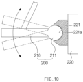
- a spherical coupling part 211 is formed in the injection nozzle 210, and a spherical coupling groove 221 to which the spherical coupling part 211 is coupled is formed in the frame 220. That is, the spherical coupling part 211 may rotate up and down or left and right within the spherical coupling groove 221, and the injection nozzle 210 may operate with the spherical coupling part 211 to adjust the angle up and down or left and right.
- the angle of the injection nozzle 210 may be adjusted up and down or left and right to match the inlet 11 of the plastic bag 10 adsorbed to the elevating member 100. As a result, the air injected from the injection nozzle 210 may be accurately injected into the inlet 11 of the plastic bag 10.
Landscapes
- Engineering & Computer Science (AREA)
- Mechanical Engineering (AREA)
- Supplying Of Containers To The Packaging Station (AREA)
Abstract
Description
- The present application claims the benefit of the priority of
Korean Patent Application No. 10-2021-0181100, filed on December 16, 2021 - The present disclosure relates to a device and method for opening a plastic bag, which is capable of automatically opening an inlet of the plastic bag.
- In general, products such as foods, medicines and articles, are packed and distributed in packaging bags in the form of a bag, and a synthetic resin is generally used as a material of the packaging bags.
- For example, the packaging bags may be provided as plastic bags in the form of an envelope, and the plastic bags each have a structure in which surfaces other than one surface are sealed. That is, the non-sealed one surface of the packaging bag serves as an inlet for accommodating the products.
- As the industry develops, a plastic bag opening device for accommodating many products in plastic bags in a short time is developed. The plastic bag opening device includes first and second adsorption pads that adsorb two opposite surfaces of the plastic bag, respectively, and a movable member that moves the first and second adsorption pads in directions that are away from each other, to open the inlet of the plastic bag.
- However, there is a limit to how the plastic bag opening device according to the related art completely opens the inlet of the plastic bag solely by the first and second adsorption pads. That is, the inlet of the plastic bag is difficult to open because of frictional force and static electricity. Accordingly, capacity utilization may be reduced and packaging failure may occur because of a plastic bag opening error.
- An object of the present invention for solving the above problems is to provide a device for opening a plastic bag, which includes an air blower to more easily open an inlet of the plastic bag, and particularly, to completely open the inlet of the plastic bag and accordingly, may increase capacity utilization and prevent an occurrence of defective packaging, and a method for opening a plastic bag using the device.
- An object of the present invention for solving the above problems is to provide a plastic bag opening device that opens an inlet of a plastic bag having a pocket shape. The plastic bag opening device may include: an elevating member that lifts the plastic bag in a state in which one surface of the plastic bag is adsorbed; and an air blower that injects air toward the inlet of the plastic bag adsorbed to the elevating member so that the inlet of the plastic bag is opened to be widened.
- The elevating member may include an adsorption pad, which adsorbs the one surface of the plastic bag, and an elevating part that allows the adsorption pad to ascend so as to lift the plastic bag adsorbed to the adsorption pad up to a horizontal line at which the air blower is disposed.
- The air blower may include an injection nozzle, which injects the air toward the inlet of the plastic bag so that the inlet of the plastic bag is opened to be widened, and a frame to which the injection nozzle is coupled. In the injection nozzle, an air injection opening may be provided to be inclined downward at a set angle with respect to the horizontal line.
- The set angle may be set to 3° to 10°.
- The injection nozzle may be coupled to the frame so that the angle is adjustable up and down or left and right.
- The plastic bag opening device may further include a rotating member that rotates the elevating member so that the inlet of the plastic bag adsorbed to the elevating member faces upward.
- The plastic bag opening device may further include a finger member provided with a pair of fingers that are inserted into the inlet of the plastic bag adsorbed to the elevating member and pull and expand the inlet of the plastic bag in two opposite directions.
- The plastic bag opening device may further include a movable member that moves the elevating member to be far away from the finger member, so that the inlet of the plastic bag is expanded by an area between the finger member and the elevating member.
- The present invention relates to a plastic bag opening method that opens an inlet of a plastic bag having a pocket shape. The plastic bag opening method may include: an elevating process of adsorbing one surface of the plastic bag and then lifting the plastic bag by using an elevating member; and an opening process of opening the inlet of the plastic bag to be widened by using an air blower to inject air toward the inlet of the plastic bag adsorbed to the elevating member so that the air injected from the air blower flows into the plastic bag through the inlet.
- In the elevating process, the elevating member may lift the plastic bag up to a horizontal line at which the air blower is disposed. In the opening process, the air blower may inject the air toward the inlet of the plastic bag so that the air is injected downward at a set angle with respect to the horizontal line.
- The set angle may be set to 3° to 10°.
- The plastic bag opening method may include a rotating process of rotating the elevating member by using a rotating member so that the inlet of the plastic bag adsorbed to the elevating member is disposed to face upward, when the opening process is completed.
- The plastic bag opening method may include a primarily expanding process of pulling and expanding the inlet of the plastic bag in two opposite directions by inserting a pair of fingers provided in a finger member into the inlet of the plastic bag adsorbed to the elevating member and moving the pair of fingers in directions that are away from each other, when the rotating process is completed.
- The plastic bag opening method may include a secondarily expanding process of expanding the inlet of the plastic bag by an area between the finger member and the elevating member by using a movable member to move the elevating member to be far away from the finger member, when the primarily expanding process is completed.
- The plastic bag opening device according to the present invention may include the air blower to inject the air into the inlet of the plastic bag and completely open the inlet of the plastic bag. Accordingly, the capacity utilization may increase, and the occurrence of the defective packaging may be prevented.
-
-
FIG. 1 is a perspective view illustrating a plastic bag according to the present invention. -
FIG. 2 is a side view illustrating a plastic bag opening device according to a first embodiment of the present invention. -
FIG. 3 is a perspective view illustrating an air blower of the plastic bag opening device according to the first embodiment of the present invention. -
FIG. 4 is a side view illustrating a rotating member of the plastic bag opening device according to the first embodiment of the present invention. -
FIG. 5 is a perspective illustrating a finger member of the plastic bag opening device according to the first embodiment of the present invention. -
FIG. 6 is a plan view illustrating an operation state of a finger member of the plastic bag opening device according to the first embodiment of the present invention. -
FIG. 7 is a plan view illustrating a movable member of the plastic bag opening device according to the first embodiment of the present invention. -
FIG. 8 is a flowchart illustrating a plastic bag opening method according to a first embodiment of the present invention. -
FIG. 9 is a perspective illustrating a plastic bag opening device according to a second embodiment of the present invention. -
FIG. 10 is a cross-sectional view taken along a line A-A inFIG. 9 . - Hereinafter, embodiments of the present invention will be described in detail with reference to the accompanying drawings to enable those skilled in the art to which the present invention pertains to easily carry out the present invention. The present invention may, however, be embodied in different forms and should not be construed as limited by the embodiments set forth herein. The parts unrelated to the description will be ruled out in the drawings in order to clearly describe the present invention. Like reference numerals refer to like elements throughout the whole specification.
- Referring to
FIG. 1 , aplastic bag 10 has a structure in the form of a pocket having one surface in which aninlet 11 is formed. Theplastic bag 10 having such a structure is kept in a state in which theplastic bag 10 is pressed flat so that onesurface 12 and theother surface 13 are in close contact with each other. When using theplastic bag 10, theinlet 11 thereof is opened to store or pack products, etc. - However, there is a problem that the
plastic bag 10 is not easily opened because of frictional force or static electricity occurring between the onesurface 12 and theother surface 13. - A plastic
bag opening device 1 according to a first embodiment of the present invention may automatically open theinlet 11 of theplastic bag 10, and particularly, completely open the inlet of the plastic bag. Accordingly, efficiency of accommodating articles may be improved. - Hereinafter, the plastic bag opening device according to the first embodiment of the present invention will be described in detail with reference to the drawings.
- As illustrated in
FIGS. 1 to 3 , the plasticbag opening device 1 according to the first embodiment of the present invention has a structure that opens theinlet 11 of theplastic bag 10 having a pocket shape. That is, the plasticbag opening device 1 according to the first embodiment of the present invention includes anelevating member 100, which lifts theplastic bag 10 in a state in which one surface 12 (a top surface of the plastic bag inFIG. 1 ) of theplastic bag 10 is adsorbed, and anair blower 200 which injects air toward theinlet 11 of theplastic bag 10 adsorbed to the elevatingmember 100 so that theinlet 11 of theplastic bag 10 is opened to be widened. - The
elevating member 100 is intended to lift theplastic bag 10. - That is, as illustrated in
FIG. 2 , the elevatingmember 100 includes anadsorption pad 110, which adsorbs the onesurface 12 of theplastic bag 10, and an elevatingpart 120 which allows theadsorption pad 110 to ascend and lifts theplastic bag 10 adsorbed to theadsorption pad 110 up to a horizontal line (0) at which theair blower 200 is disposed. - Here, the
adsorption pad 110 may be provided in plurality so as to lift the entire onesurface 12 provided at a side of theinlet 11 of theplastic bag 10, and preferably, five ormore adsorption pads 110 may be provided. - In particular, the
adsorption pad 110 may have a structure in which an air suction force is used to adsorb the onesurface 12 of theplastic bag 10. The elevatingpart 120 may be provided as a hydraulic cylinder or pneumatic cylinder that allows theadsorption pad 110 to ascend or return to an initial position. - The elevating
member 100 having the structure as described above may stably adsorb the onesurface 12 of theplastic bag 10 and effectively lift the adsorbedplastic bag 10. - The
air blower 200 is intended to open the inlet of the plastic bag. - That is, as illustrated in
FIG. 3 , theair blower 200 includes aninjection nozzle 210, which injects the air toward theinlet 11 of theplastic bag 10 so that theinlet 11 of theplastic bag 10 is opened to be widened, and aframe 220 to which theinjection nozzle 210 is coupled. - Here, the
frame 220 is formed to extend in a direction corresponding to theinlet 11 of the plastic bag 10 (a front and rear direction inFIG. 1 ), and theinjection nozzle 210 is provided in plurality at set intervals on one surface of theframe 220, which faces theplastic bag 10. - Here, the
injection nozzle 210 may be provided to face theinlet 11 of theplastic bag 10 so that an air injection opening through which the air is injected is inclined downward at a set angle α° with respect to the horizontal line (O). The air injected from theinjection nozzle 210 may be injected toward theother surface 13 rather than the onesurface 12 of theplastic bag 10. Accordingly, theother surface 13 of theplastic bag 10, which adheres to the onesurface 12 by static electricity, etc., may be easily separated to open theinlet 11 of theplastic bag 10. - Here, the set angle α° may be set to 3° to 10°, and preferably, may be provided as 5° to 8°. When an injection angle of the
injection nozzle 210 is 3° or less, there is no significant difference compared to the case of injecting toward the horizontal line. When the injection angle is 10° or greater, the air may be injected outside theinlet 11, and thus the efficiency may be reduced. - In an operation state of the plastic
bag opening device 1 according to the first embodiment of the present invention having the structure as described above, the elevatingmember 100 lifts the onesurface 12 of theplastic bag 10 in the adsorbed state. Here, the other surface (a bottom surface of the plastic bag inFIG. 1 ) of theplastic bag 10 may have a portion adhering to the one surface by static electricity. The entirety of theother surface 13 may also adhere to the one surface, and the entirety of theother surface 13 may also be separated from the one surface due to the load. - Then, the
air blower 200 is used to inject the air toward theinlet 11 of theplastic bag 10. The air injected by theair blower 200 may flow into theinlet 11 to open theinlet 11, and part of the air having flowed into theplastic bag 10 may be discharged through theinlet 11 to reopen theinlet 11. - Thus, as the plastic
bag opening device 1 according to the first embodiment of the present invention includes the elevatingmember 100 and theair blower 200, theinlet 11 of theplastic bag 10 may be opened to be completely widened. - The plastic
bag opening device 1 according to the first embodiment of the present invention may further include a rotatingmember 300 that rotates the elevatingmember 100 so that theinlet 11 of theplastic bag 10 faces upward. - That is, as the rotating
member 300 allows theinlet 11 of theplastic bag 10 to be disposed to face upward as illustrated inFIG. 4 , a product may be more easily introduced into theplastic bag 10. - In one example, the rotating
member 300 includes arotating body 310, to which the elevatingmember 100 is rotatably coupled, and arotating part 320 which rotates the elevatingmember 100 coupled to therotating body 310 so that theinlet 11 of theplastic bag 10 adsorbed to the elevatingmember 100 is disposed to face upward. Therotating part 320 may be a driving motor. - The plastic
bag opening device 1 according to the first embodiment of the present invention may further include afinger member 400 that pulls theinlet 11 of theplastic bag 10 to primarily expand theinlet 11 of theplastic bag 10 in two opposite directions. - That is, as illustrated in
FIGS. 5 and6 , thefinger member 400 includes a pair offingers 410, and the pair offingers 410 pulls theinlet 11 of theplastic bag 10 adsorbed to the elevatingmember 100 in the two opposite directions while moving in directions that are away from each other, in a state inserted into theinlet 11 of theplastic bag 10. - In one example, the
finger member 400 includes the pair offingers 410, which pulls theinlet 11 of theplastic bag 10 adsorbed to the elevatingmember 100 in the two opposite directions while moving in the directions that are away from each other, in the state inserted into theinlet 11 of theplastic bag 10, afirst driving part 420, which allows the pair offingers 410 to descend toward theplastic bag 10 so that the pair offingers 410 are inserted into theinlet 11 of theplastic bag 10, and a second driving part 430 which allows the pair offingers 410 to move in the directions that are away from each other. - The
finger member 400 having such a structure may expand theinlet 11 of theplastic bag 10 in the two opposite directions, and may also prevent theinlet 11 of theplastic bag 10 from sagging. - The plastic
bag opening device 1 according to the first embodiment of the present invention may further include amovable member 500 for secondarily expanding theinlet 11 of theplastic bag 10. - That is, as illustrated in
FIG. 7 , themovable member 500 moves the elevatingmember 100 to be far away from thefinger member 400 so that theinlet 11 of theplastic bag 10 is secondarily expanded by an area between thefinger member 400 and the elevatingmember 100. In other words, the onesurface 12 of the plastic bag is adsorbed to the elevatingmember 100, and theother surface 13 of theplastic bag 10 is supported by thefinger member 400. Thus, when the movable member moves the elevatingmember 100, theinlet 11 of theplastic bag 10 may be expanded while the onesurface 12 of theplastic bag 10 moves together with the elevatingmember 100. - Hereinafter, an opening method using the plastic bag opening device according to the first embodiment of the present invention will be described.
- As illustrated in
FIG. 8 , a plastic bag opening method according to a first embodiment of present invention includes an elevating process, an opening process, a rotating process, a primarily expanding process, and a secondarily expanding process in order that aninlet 11 of aplastic bag 10 having a pocket shape is opened to be widened. - The plastic bag opening method according to the first embodiment of present invention uses the plastic bag opening device according to the first embodiment of the present invention described above, and the plastic
bag opening device 1 according to the first embodiment of the present invention includes an elevatingmember 100, anair blower 200, a rotatingmember 300, afinger member 400, and amovable member 500. - Referring to
FIG. 2 , in the elevating process, the elevatingmember 100 is used to adsorb one surface 12 (a top surface inFIG. 1 ) of aplastic bag 10 stacked at an uppermost side of stackedplastic bags 10 and then to lift theplastic bag 10. - That is, the elevating
member 100 adsorbs the onesurface 12 of theplastic bag 10 through anadsorption pad 110 and lifts theplastic bag 10 through an elevatingpart 120. Here, the elevatingmember 100 lifts theplastic bag 10 up to a horizontal line (O) at which theair blower 200 is disposed. - Here, the one surface 12 (the top surface in
FIG. 1 ) and the other surface 13 (a bottom surface inFIG. 1 ), which are disposed at a side of aninlet 11 of theplastic bag 10, may have an entirely close contact state or a partially close contact state by adhesion or static electricity. - Referring to
FIG. 3 , in the opening process, theair blower 200 is used to inject air toward theinlet 11 of theplastic bag 10 adsorbed to the elevatingmember 100. Then, theinlet 11 may be opened by pressure of the air injected from theair blower 200. In particular, even when the onesurface 12 and theother surface 13 that are disposed at the side of theinlet 11 of theplastic bag 10 are in close contact with each other, the onesurface 12 and theother surface 13 may be easily separated from each other by the air pressure, and as a result, theinlet 11 of theplastic bag 10 may be opened to be widened. - Furthermore, part of the air having flowed into the
plastic bag 10 may be discharged to the outside through theinlet 11 of theplastic bag 10, and theinlet 11 of theplastic bag 10 may be completely opened by the air discharged to the outside of theplastic bag 10. - In the opening process, the
air blower 200 may inject the air toward theinlet 11 of theplastic bag 10 so that the air is injected downward at a set angle α° with respect to the horizontal line. That is, theair blower 200 may inject the air toward theother surface 13 disposed at the side of theinlet 11 of theplastic bag 10 and accordingly, theother surface 13 of theplastic bag 10 may be easily separated from the onesurface 12 of theplastic bag 10. As a result, theinlet 11 may be effectively opened. - The set angle α° may be set to 3° to 10°, and preferably, may be set to 5° to 7°.
- When the
inlet 11 of theplastic bag 10 is opened, the rotating process, the primarily expanding process, and the secondarily expanding process may be performed for expanding an area in aninlet 11 direction of theplastic bag 10 in order to easily accommodate articles. - Referring to
FIG. 5 , the rotating process is intended to dispose theinlet 11 of theplastic bag 10 to face upward, and when the opening process is completed, the rotatingmember 300 is used to rotate the elevatingmember 100 so that theinlet 11 of theplastic bag 10 adsorbed to the elevatingmember 100 is disposed to face upward. - Referring to
FIG. 6 , the primarily expanding process is intended to primarily expand theinlet 11 of theplastic bag 10 and prevent theinlet 11 from sagging, and when the rotating process is completed, a pair offingers 410 provided in thefinger member 400 are inserted into theinlet 11 of theplastic bag 10 adsorbed to the elevatingmember 100, and the pair offingers 410 are moved in directions that are away from each other. Then, theinlet 11 of theplastic bag 10 may be pulled by the pair offingers 410 in two opposite directions to primarily expand theinlet 11 of theplastic bag 10. - Referring to
FIG. 7 , in the secondarily expanding process, themovable member 500 is used to move the elevatingmember 100 to be far away from thefinger member 400 when the primarily expanding process is completed. Then, the onesurface 12 of theplastic bag 10 moves together with the elevatingmember 100, and as a result, theinlet 11 of theplastic bag 10 may be secondarily expanded by an area (or a distance) between thefinger member 400 and the elevatingmember 100. - When the processes as described above are completed, the articles may be conveniently inserted into the
inlet 11 of theplastic bag 10 and packed. - Hereinafter, another embodiment of the present invention will be described using the same reference symbol for the same element as the embodiment described above, and duplicate description will be omitted.
- As illustrated in
FIGS. 9 and10 , a plasticbag opening device 1 according to a second embodiment of present invention includes an elevatingmember 100 and anair blower 200. Theair blower 200 includes aninjection nozzle 210, which injects air toward aninlet 11 of aplastic bag 10 so that theinlet 11 of theplastic bag 10 is opened to be widened, and aframe 220 to which theinjection nozzle 210 is coupled. - Here, the
injection nozzle 210 may be coupled to theframe 220 so that an angle is adjustable up and down or left and right. - In one example, referring to
FIG. 10 , aspherical coupling part 211 is formed in theinjection nozzle 210, and aspherical coupling groove 221 to which thespherical coupling part 211 is coupled is formed in theframe 220. That is, thespherical coupling part 211 may rotate up and down or left and right within thespherical coupling groove 221, and theinjection nozzle 210 may operate with thespherical coupling part 211 to adjust the angle up and down or left and right. - Thus, in the plastic bag opening device according to the second embodiment of present invention, the angle of the
injection nozzle 210 may be adjusted up and down or left and right to match theinlet 11 of theplastic bag 10 adsorbed to the elevatingmember 100. As a result, the air injected from theinjection nozzle 210 may be accurately injected into theinlet 11 of theplastic bag 10. - The scope of the present invention is defined by the appended claims rather than the foregoing description. Various modifications made within the meaning of an equivalent of the claims of the invention and within the claims are to be regarded to be in the scope of the present invention.
-
- 10: Plastic bag
- 11: Inlet
- 12: One surface
- 13: The other surface
- 100: Elevating member
- 110: Adsorption pad
- 120: Elevating part
- 200: Air blower
- 210: Injection nozzle
- 220: Frame
- 300: Rotating member
- 310: Rotating body
- 320: Rotating part
- 400: Finger member
- 410; Finger
- 420: First driving part
- 430: Second driving part
- 500: Movable member
Claims (14)
- A plastic bag opening device configured to open an inlet of a plastic bag having a pocket shape, the plastic bag opening device comprising:an elevating member configured to lift the plastic bag in a state in which one surface of the plastic bag is adsorbed; andan air blower configured to inject air toward the inlet of the plastic bag adsorbed to the elevating member so that the inlet of the plastic bag is opened to be widened.
- The device of claim 1, wherein the elevating member comprises:an adsorption pad configured to adsorb the one surface of the plastic bag; andan elevating part configured to allow the adsorption pad to ascend so as to lift the plastic bag adsorbed to the adsorption pad up to a horizontal line at which the air blower is disposed.
- The plastic bag opening device of claim 2, wherein the air blower comprises an injection nozzle configured to inject the air toward the inlet of the plastic bag so that the inlet of the plastic bag is opened to be widened, and a frame to which the injection nozzle is coupled,
wherein, in the injection nozzle, an air injection opening is provided to be inclined downward at a set angle with respect to the horizontal line. - The plastic bag opening device of claim 3, wherein the set angle is set to 3° to 10°.
- The device of claim 3, wherein the injection nozzle is coupled to the frame so that the angle is adjustable up and down or left and right.
- The plastic bag opening device of claim 1, further comprising a rotating member configured to rotate the elevating member so that the inlet of the plastic bag adsorbed to the elevating member faces upward.
- The plastic bag opening device of claim 6, further comprising a finger member provided with a pair of fingers that are inserted into the inlet of the plastic bag adsorbed to the elevating member and configured to pull and expand the inlet of the plastic bag in two opposite directions.
- The plastic bag opening device of claim 7, further comprising a movable member configured to move the elevating member to be far away from the finger member, so that the inlet of the plastic bag is expanded by an area between the finger member and the elevating member.
- A plastic bag opening method that opens an inlet of a plastic bag having a pocket shape, the plastic bag opening method comprising:an elevating process of adsorbing one surface of the plastic bag and then lifting the plastic bag by using an elevating member; andan opening process of opening the inlet of the plastic bag to be widened by using an air blower to inject air toward the inlet of the plastic bag adsorbed to the elevating member so that the air injected from the air blower flows into the plastic bag through the inlet.
- The plastic bag opening method of claim 9, wherein, in the elevating process, the elevating member lifts the plastic bag up to a horizontal line at which the air blower is disposed, and
in the opening process, the air blower injects the air toward the inlet of the plastic bag so that the air is injected downward at a set angle with respect to the horizontal line. - The plastic bag opening method of claim 10, wherein the set angle is set to 3° to 10°.
- The plastic bag opening method of claim 9, further comprising a rotating process of rotating the elevating member by using a rotating member so that the inlet of the plastic bag adsorbed to the elevating member is disposed to face upward, when the opening process is completed.
- The plastic bag opening method of claim 12, further comprising a primarily expanding process of pulling and expanding the inlet of the plastic bag in two opposite directions by inserting a pair of fingers provided in a finger member into the inlet of the plastic bag adsorbed to the elevating member and moving the pair of fingers in directions that are away from each other, when the rotating process is completed.
- The plastic bag opening method of claim 13, further comprising a secondarily expanding process of expanding the inlet of the plastic bag by an area between the finger member and the elevating member by using a movable member to move the elevating member to be far away from the finger member, when the primarily expanding process is completed.
Applications Claiming Priority (2)
| Application Number | Priority Date | Filing Date | Title |
|---|---|---|---|
| KR1020210181100A KR102944580B1 (en) | 2021-12-16 | 2021-12-16 | Opening device opening method and for plastic bag |
| PCT/KR2022/017132 WO2023113229A1 (en) | 2021-12-16 | 2022-11-03 | Plastic bag opening apparatus and opening method |
Publications (3)
| Publication Number | Publication Date |
|---|---|
| EP4317000A1 true EP4317000A1 (en) | 2024-02-07 |
| EP4317000A4 EP4317000A4 (en) | 2025-01-08 |
| EP4317000B1 EP4317000B1 (en) | 2025-07-09 |
Family
ID=86772950
Family Applications (1)
| Application Number | Title | Priority Date | Filing Date |
|---|---|---|---|
| EP22907700.3A Active EP4317000B1 (en) | 2021-12-16 | 2022-11-03 | Plastic bag opening apparatus and opening method |
Country Status (8)
| Country | Link |
|---|---|
| US (1) | US12397952B2 (en) |
| EP (1) | EP4317000B1 (en) |
| JP (1) | JP7581613B2 (en) |
| KR (1) | KR102944580B1 (en) |
| CN (1) | CN117337260B (en) |
| ES (1) | ES3047665T3 (en) |
| HU (1) | HUE073022T2 (en) |
| WO (1) | WO2023113229A1 (en) |
Family Cites Families (33)
| Publication number | Priority date | Publication date | Assignee | Title |
|---|---|---|---|---|
| DE2527693A1 (en) * | 1975-06-21 | 1977-01-13 | Behn Verpackung Erwin | Stacked sack opening mechanism - tilts suction device away from mouth after exhaustion and inserts finger |
| JPS591928Y2 (en) * | 1980-12-27 | 1984-01-19 | 東洋自動機株式会社 | Bag opening forming device |
| JPS6420409U (en) * | 1987-07-24 | 1989-02-01 | ||
| US4815255A (en) * | 1987-09-09 | 1989-03-28 | Enterprises International, Inc. | Plastic bag placement apparatus and method |
| WO1992012900A1 (en) * | 1991-01-26 | 1992-08-06 | Bühler AG Maschinenfabrik | Process for automatically preparing bags and bag suspension device |
| JP3331475B2 (en) * | 1992-03-10 | 2002-10-07 | 株式会社川島製作所 | How to open a gusset bag |
| US5315812A (en) * | 1992-04-23 | 1994-05-31 | Yakima Wire Works | Method and apparatus for bagging objects |
| JPH08156917A (en) * | 1994-12-05 | 1996-06-18 | Terada Seisakusho:Kk | Automatic mounting apparatus for tea making main bag |
| JP3731832B2 (en) * | 1996-02-29 | 2006-01-05 | 不双産業株式会社 | Vertical filling and packaging equipment |
| US6089514A (en) * | 1998-09-08 | 2000-07-18 | Durabag Co., Inc. | Swing-arm bagging rack for supporting multiple styles of packs of plastic bag |
| KR100391971B1 (en) | 2001-05-26 | 2003-07-22 | 미래산전 주식회사 | robot apparatus for opening envelope |
| KR100438122B1 (en) | 2004-03-29 | 2004-07-03 | 주식회사리팩 | Zipper-bag opener for bag filling machine |
| KR100460965B1 (en) | 2004-06-11 | 2004-12-09 | 주식회사리팩 | Link-worked bag opener for bag filling and sealing machine |
| JP2006256658A (en) * | 2005-03-17 | 2006-09-28 | Toyo Jidoki Co Ltd | How to open a packaging bag with a chuck |
| JP2007137429A (en) * | 2005-11-14 | 2007-06-07 | Yashiomi Seisakusho:Kk | Bagging apparatus |
| JP4160606B2 (en) | 2006-05-31 | 2008-10-01 | 株式会社トーヨー | Bag packing equipment |
| KR200432422Y1 (en) | 2006-09-07 | 2006-12-01 | 세진테크 주식회사 | Packing Bag Automatic Filling Packing Machine |
| US20080110132A1 (en) * | 2006-11-14 | 2008-05-15 | Grupo Bimbo, S.A.B. De C.V. | Automated bags supply system for filling bags with products |
| JP4918152B2 (en) * | 2010-05-24 | 2012-04-18 | 株式会社トーヨー | Vacuum packaging equipment |
| KR101228062B1 (en) * | 2010-09-09 | 2013-01-30 | 삼성중공업 주식회사 | Blasting nozzle |
| KR101281542B1 (en) | 2011-07-15 | 2013-07-03 | 세진테크 주식회사 | Zipper pack opening apparatus |
| JP5913992B2 (en) * | 2012-01-12 | 2016-05-11 | 東洋自動機株式会社 | Bag mouth opening method and opening device |
| KR101242769B1 (en) | 2012-12-06 | 2013-03-25 | 주식회사 린도이앤씨 | Bag compaction system |
| KR101446670B1 (en) | 2014-06-18 | 2014-10-06 | 안광태 | An automatic feed packing device |
| KR20180005372A (en) | 2016-07-06 | 2018-01-16 | 주식회사 솔팩 | A pouch supply apparatus for rotary type automatic packing machine |
| KR102092123B1 (en) * | 2016-08-30 | 2020-03-23 | 오성시스템 주식회사 | Zipper-bag open apparatus for auto packing machine |
| KR101841425B1 (en) * | 2016-10-05 | 2018-03-23 | 두성산업(주) | Packaging apparatus using automatic combination weighing |
| JP6337166B1 (en) * | 2017-02-21 | 2018-06-06 | 株式会社トーヨー | Seasoning liquid filling bag filling and packaging equipment |
| US10836525B1 (en) * | 2017-03-07 | 2020-11-17 | Amazon Technologies, Inc. | Robotic gripper for bagging items |
| KR20180111121A (en) * | 2017-03-31 | 2018-10-11 | (주)이티에스 | Electrolyte injection apparatus |
| KR20190103842A (en) | 2018-02-28 | 2019-09-05 | 안남옥 | Apparatus for opening bag and packaging system using the same |
| JP6978786B2 (en) | 2019-04-12 | 2021-12-08 | 株式会社トーヨー | Self-supporting bag packaging device |
| CN210761578U (en) * | 2019-09-24 | 2020-06-16 | 厦门佰顺兴自动化科技有限公司 | Bag feeding and opening device for M-shaped folded plastic bag |
-
2021
- 2021-12-16 KR KR1020210181100A patent/KR102944580B1/en active Active
-
2022
- 2022-11-03 JP JP2023566024A patent/JP7581613B2/en active Active
- 2022-11-03 HU HUE22907700A patent/HUE073022T2/en unknown
- 2022-11-03 EP EP22907700.3A patent/EP4317000B1/en active Active
- 2022-11-03 CN CN202280035846.1A patent/CN117337260B/en active Active
- 2022-11-03 US US18/563,313 patent/US12397952B2/en active Active
- 2022-11-03 WO PCT/KR2022/017132 patent/WO2023113229A1/en not_active Ceased
- 2022-11-03 ES ES22907700T patent/ES3047665T3/en active Active
Also Published As
| Publication number | Publication date |
|---|---|
| EP4317000B1 (en) | 2025-07-09 |
| US12397952B2 (en) | 2025-08-26 |
| ES3047665T3 (en) | 2025-12-04 |
| CN117337260A (en) | 2024-01-02 |
| KR102944580B1 (en) | 2026-03-26 |
| JP7581613B2 (en) | 2024-11-13 |
| US20240270424A1 (en) | 2024-08-15 |
| KR20230091713A (en) | 2023-06-23 |
| WO2023113229A1 (en) | 2023-06-22 |
| CN117337260B (en) | 2025-12-30 |
| HUE073022T2 (en) | 2025-12-28 |
| JP2024515981A (en) | 2024-04-11 |
| EP4317000A4 (en) | 2025-01-08 |
Similar Documents
| Publication | Publication Date | Title |
|---|---|---|
| KR101805208B1 (en) | Method and apparatus for opening inlet of bag | |
| CN206125534U (en) | Article font advances to push away feeding mechanism | |
| CN105383721B (en) | The packaging facilities and packing method of absorbent commodity | |
| CN111731578B (en) | Open-package-packaging integrated system | |
| CN118270540A (en) | Automatic stacking device of particle vacuum packaging machine | |
| US12397952B2 (en) | Device and method for opening plastic bag | |
| JP7130231B2 (en) | Vertical packaging machine and packaging method | |
| CN212767091U (en) | Material packing system | |
| CN115996875A (en) | An automated method and system for packaging flexible items | |
| CN210284752U (en) | Product into tray and box production line | |
| CN117184583A (en) | Foam packaging assembly equipment for rotary cosmetic box | |
| CN117916169A (en) | Slot type air packaging device and packaging method thereof | |
| JP6254370B2 (en) | Picking equipment | |
| KR100798753B1 (en) | Packing machine | |
| JP5808642B2 (en) | Box making equipment | |
| CN222808812U (en) | Fast-paced overturning and carrying device | |
| JP2011084332A (en) | Boxing device and boxing method | |
| CN208629566U (en) | A kind of plastic bottle row cutting machine | |
| CN208102492U (en) | A kind of packaging facilities packaging system | |
| KR101976639B1 (en) | Apparatus to separate a sheet from laminated mask packs | |
| US11745907B2 (en) | Clamping and conveying device for material bag filling system | |
| JP3840591B2 (en) | Method and apparatus for supplying partition in boxing machine | |
| JP2019142539A (en) | Boxing device | |
| CN217836152U (en) | Moon cake boxing equipment | |
| CN206615474U (en) | A kind of manual packing apparatus of the separating-closing type of button cell |
Legal Events
| Date | Code | Title | Description |
|---|---|---|---|
| STAA | Information on the status of an ep patent application or granted ep patent |
Free format text: STATUS: THE INTERNATIONAL PUBLICATION HAS BEEN MADE |
|
| PUAI | Public reference made under article 153(3) epc to a published international application that has entered the european phase |
Free format text: ORIGINAL CODE: 0009012 |
|
| STAA | Information on the status of an ep patent application or granted ep patent |
Free format text: STATUS: REQUEST FOR EXAMINATION WAS MADE |
|
| 17P | Request for examination filed |
Effective date: 20231101 |
|
| AK | Designated contracting states |
Kind code of ref document: A1 Designated state(s): AL AT BE BG CH CY CZ DE DK EE ES FI FR GB GR HR HU IE IS IT LI LT LU LV MC ME MK MT NL NO PL PT RO RS SE SI SK SM TR |
|
| REG | Reference to a national code |
Ref legal event code: R079 Free format text: PREVIOUS MAIN CLASS: B65B0043360000 Ref country code: DE Ref document number: 602022017486 Country of ref document: DE Ipc: B31B0070000000 |
|
| RIC1 | Information provided on ipc code assigned before grant |
Ipc: B65B 43/28 20060101ALI20240912BHEP Ipc: B65B 43/36 20060101ALI20240912BHEP Ipc: B65B 43/18 20060101ALI20240912BHEP Ipc: B31B 70/00 20170101AFI20240912BHEP |
|
| A4 | Supplementary search report drawn up and despatched |
Effective date: 20241206 |
|
| RIC1 | Information provided on ipc code assigned before grant |
Ipc: B65B 43/28 20060101ALI20241202BHEP Ipc: B65B 43/36 20060101ALI20241202BHEP Ipc: B65B 43/18 20060101ALI20241202BHEP Ipc: B31B 70/00 20170101AFI20241202BHEP |
|
| DAV | Request for validation of the european patent (deleted) | ||
| DAX | Request for extension of the european patent (deleted) | ||
| GRAP | Despatch of communication of intention to grant a patent |
Free format text: ORIGINAL CODE: EPIDOSNIGR1 |
|
| STAA | Information on the status of an ep patent application or granted ep patent |
Free format text: STATUS: GRANT OF PATENT IS INTENDED |
|
| INTG | Intention to grant announced |
Effective date: 20250414 |
|
| GRAS | Grant fee paid |
Free format text: ORIGINAL CODE: EPIDOSNIGR3 |
|
| GRAA | (expected) grant |
Free format text: ORIGINAL CODE: 0009210 |
|
| STAA | Information on the status of an ep patent application or granted ep patent |
Free format text: STATUS: THE PATENT HAS BEEN GRANTED |
|
| P01 | Opt-out of the competence of the unified patent court (upc) registered |
Free format text: CASE NUMBER: APP_24895/2025 Effective date: 20250526 |
|
| AK | Designated contracting states |
Kind code of ref document: B1 Designated state(s): AL AT BE BG CH CY CZ DE DK EE ES FI FR GB GR HR HU IE IS IT LI LT LU LV MC ME MK MT NL NO PL PT RO RS SE SI SK SM TR |
|
| REG | Reference to a national code |
Ref country code: GB Ref legal event code: FG4D |
|
| REG | Reference to a national code |
Ref country code: CH Ref legal event code: EP |
|
| REG | Reference to a national code |
Ref country code: IE Ref legal event code: FG4D |
|
| REG | Reference to a national code |
Ref country code: DE Ref legal event code: R096 Ref document number: 602022017486 Country of ref document: DE |
|
| REG | Reference to a national code |
Ref country code: NL Ref legal event code: MP Effective date: 20250709 |
|
| REG | Reference to a national code |
Ref country code: ES Ref legal event code: FG2A Ref document number: 3047665 Country of ref document: ES Kind code of ref document: T3 Effective date: 20251204 |
|
| PG25 | Lapsed in a contracting state [announced via postgrant information from national office to epo] |
Ref country code: PT Free format text: LAPSE BECAUSE OF FAILURE TO SUBMIT A TRANSLATION OF THE DESCRIPTION OR TO PAY THE FEE WITHIN THE PRESCRIBED TIME-LIMIT Effective date: 20251110 |
|
| PGFP | Annual fee paid to national office [announced via postgrant information from national office to epo] |
Ref country code: HU Payment date: 20251127 Year of fee payment: 4 |
|
| PG25 | Lapsed in a contracting state [announced via postgrant information from national office to epo] |
Ref country code: NL Free format text: LAPSE BECAUSE OF FAILURE TO SUBMIT A TRANSLATION OF THE DESCRIPTION OR TO PAY THE FEE WITHIN THE PRESCRIBED TIME-LIMIT Effective date: 20250709 |
|
| REG | Reference to a national code |
Ref country code: AT Ref legal event code: MK05 Ref document number: 1811508 Country of ref document: AT Kind code of ref document: T Effective date: 20250709 |
|
| REG | Reference to a national code |
Ref country code: HU Ref legal event code: AG4A Ref document number: E073022 Country of ref document: HU |
|
| PG25 | Lapsed in a contracting state [announced via postgrant information from national office to epo] |
Ref country code: IS Free format text: LAPSE BECAUSE OF FAILURE TO SUBMIT A TRANSLATION OF THE DESCRIPTION OR TO PAY THE FEE WITHIN THE PRESCRIBED TIME-LIMIT Effective date: 20251109 |
|
| PGFP | Annual fee paid to national office [announced via postgrant information from national office to epo] |
Ref country code: DE Payment date: 20251020 Year of fee payment: 4 |
|
| PG25 | Lapsed in a contracting state [announced via postgrant information from national office to epo] |
Ref country code: NO Free format text: LAPSE BECAUSE OF FAILURE TO SUBMIT A TRANSLATION OF THE DESCRIPTION OR TO PAY THE FEE WITHIN THE PRESCRIBED TIME-LIMIT Effective date: 20251009 |
|
| REG | Reference to a national code |
Ref country code: LT Ref legal event code: MG9D |
|
| PG25 | Lapsed in a contracting state [announced via postgrant information from national office to epo] |
Ref country code: AT Free format text: LAPSE BECAUSE OF FAILURE TO SUBMIT A TRANSLATION OF THE DESCRIPTION OR TO PAY THE FEE WITHIN THE PRESCRIBED TIME-LIMIT Effective date: 20250709 |
|
| PG25 | Lapsed in a contracting state [announced via postgrant information from national office to epo] |
Ref country code: FI Free format text: LAPSE BECAUSE OF FAILURE TO SUBMIT A TRANSLATION OF THE DESCRIPTION OR TO PAY THE FEE WITHIN THE PRESCRIBED TIME-LIMIT Effective date: 20250709 |
|
| PG25 | Lapsed in a contracting state [announced via postgrant information from national office to epo] |
Ref country code: HR Free format text: LAPSE BECAUSE OF FAILURE TO SUBMIT A TRANSLATION OF THE DESCRIPTION OR TO PAY THE FEE WITHIN THE PRESCRIBED TIME-LIMIT Effective date: 20250709 |
|
| PGFP | Annual fee paid to national office [announced via postgrant information from national office to epo] |
Ref country code: FR Payment date: 20251021 Year of fee payment: 4 |
|
| PG25 | Lapsed in a contracting state [announced via postgrant information from national office to epo] |
Ref country code: GR Free format text: LAPSE BECAUSE OF FAILURE TO SUBMIT A TRANSLATION OF THE DESCRIPTION OR TO PAY THE FEE WITHIN THE PRESCRIBED TIME-LIMIT Effective date: 20251010 |
|
| PGFP | Annual fee paid to national office [announced via postgrant information from national office to epo] |
Ref country code: BE Payment date: 20251020 Year of fee payment: 4 |
|
| PG25 | Lapsed in a contracting state [announced via postgrant information from national office to epo] |
Ref country code: SE Free format text: LAPSE BECAUSE OF FAILURE TO SUBMIT A TRANSLATION OF THE DESCRIPTION OR TO PAY THE FEE WITHIN THE PRESCRIBED TIME-LIMIT Effective date: 20250709 |
|
| PG25 | Lapsed in a contracting state [announced via postgrant information from national office to epo] |
Ref country code: LV Free format text: LAPSE BECAUSE OF FAILURE TO SUBMIT A TRANSLATION OF THE DESCRIPTION OR TO PAY THE FEE WITHIN THE PRESCRIBED TIME-LIMIT Effective date: 20250709 |
|
| PG25 | Lapsed in a contracting state [announced via postgrant information from national office to epo] |
Ref country code: BG Free format text: LAPSE BECAUSE OF FAILURE TO SUBMIT A TRANSLATION OF THE DESCRIPTION OR TO PAY THE FEE WITHIN THE PRESCRIBED TIME-LIMIT Effective date: 20250709 Ref country code: PL Free format text: LAPSE BECAUSE OF FAILURE TO SUBMIT A TRANSLATION OF THE DESCRIPTION OR TO PAY THE FEE WITHIN THE PRESCRIBED TIME-LIMIT Effective date: 20250709 |
|
| PG25 | Lapsed in a contracting state [announced via postgrant information from national office to epo] |
Ref country code: RS Free format text: LAPSE BECAUSE OF FAILURE TO SUBMIT A TRANSLATION OF THE DESCRIPTION OR TO PAY THE FEE WITHIN THE PRESCRIBED TIME-LIMIT Effective date: 20251009 |
|
| PGFP | Annual fee paid to national office [announced via postgrant information from national office to epo] |
Ref country code: ES Payment date: 20251215 Year of fee payment: 4 |
|
| PG25 | Lapsed in a contracting state [announced via postgrant information from national office to epo] |
Ref country code: RO Free format text: LAPSE BECAUSE OF FAILURE TO SUBMIT A TRANSLATION OF THE DESCRIPTION OR TO PAY THE FEE WITHIN THE PRESCRIBED TIME-LIMIT Effective date: 20250709 |
|
| PG25 | Lapsed in a contracting state [announced via postgrant information from national office to epo] |
Ref country code: SM Free format text: LAPSE BECAUSE OF FAILURE TO SUBMIT A TRANSLATION OF THE DESCRIPTION OR TO PAY THE FEE WITHIN THE PRESCRIBED TIME-LIMIT Effective date: 20250709 |
|
| PG25 | Lapsed in a contracting state [announced via postgrant information from national office to epo] |
Ref country code: DK Free format text: LAPSE BECAUSE OF FAILURE TO SUBMIT A TRANSLATION OF THE DESCRIPTION OR TO PAY THE FEE WITHIN THE PRESCRIBED TIME-LIMIT Effective date: 20250709 |
|
| PG25 | Lapsed in a contracting state [announced via postgrant information from national office to epo] |
Ref country code: IT Free format text: LAPSE BECAUSE OF FAILURE TO SUBMIT A TRANSLATION OF THE DESCRIPTION OR TO PAY THE FEE WITHIN THE PRESCRIBED TIME-LIMIT Effective date: 20250709 |
|
| PG25 | Lapsed in a contracting state [announced via postgrant information from national office to epo] |
Ref country code: CZ Free format text: LAPSE BECAUSE OF FAILURE TO SUBMIT A TRANSLATION OF THE DESCRIPTION OR TO PAY THE FEE WITHIN THE PRESCRIBED TIME-LIMIT Effective date: 20250709 |
|
| PG25 | Lapsed in a contracting state [announced via postgrant information from national office to epo] |
Ref country code: SK Free format text: LAPSE BECAUSE OF FAILURE TO SUBMIT A TRANSLATION OF THE DESCRIPTION OR TO PAY THE FEE WITHIN THE PRESCRIBED TIME-LIMIT Effective date: 20250709 Ref country code: EE Free format text: LAPSE BECAUSE OF FAILURE TO SUBMIT A TRANSLATION OF THE DESCRIPTION OR TO PAY THE FEE WITHIN THE PRESCRIBED TIME-LIMIT Effective date: 20250709 |
|
| PLBE | No opposition filed within time limit |
Free format text: ORIGINAL CODE: 0009261 |
|
| STAA | Information on the status of an ep patent application or granted ep patent |
Free format text: STATUS: NO OPPOSITION FILED WITHIN TIME LIMIT |