EP4316911A1 - Kraftfahrzeuglichtsystem zur abstrahlung von positionsbegrenzten bodenprojektionen - Google Patents
Kraftfahrzeuglichtsystem zur abstrahlung von positionsbegrenzten bodenprojektionen Download PDFInfo
- Publication number
- EP4316911A1 EP4316911A1 EP22188112.1A EP22188112A EP4316911A1 EP 4316911 A1 EP4316911 A1 EP 4316911A1 EP 22188112 A EP22188112 A EP 22188112A EP 4316911 A1 EP4316911 A1 EP 4316911A1
- Authority
- EP
- European Patent Office
- Prior art keywords
- projection
- motor vehicle
- projection devices
- chassis
- chassis height
- Prior art date
- Legal status (The legal status is an assumption and is not a legal conclusion. Google has not performed a legal analysis and makes no representation as to the accuracy of the status listed.)
- Granted
Links
Images


Classifications
-
- B—PERFORMING OPERATIONS; TRANSPORTING
- B60—VEHICLES IN GENERAL
- B60Q—ARRANGEMENT OF SIGNALLING OR LIGHTING DEVICES, THE MOUNTING OR SUPPORTING THEREOF OR CIRCUITS THEREFOR, FOR VEHICLES IN GENERAL
- B60Q1/00—Arrangement of optical signalling or lighting devices, the mounting or supporting thereof or circuits therefor
- B60Q1/02—Arrangement of optical signalling or lighting devices, the mounting or supporting thereof or circuits therefor the devices being primarily intended to illuminate the way ahead or to illuminate other areas of way or environments
- B60Q1/24—Arrangement of optical signalling or lighting devices, the mounting or supporting thereof or circuits therefor the devices being primarily intended to illuminate the way ahead or to illuminate other areas of way or environments for lighting other areas than only the way ahead
- B60Q1/247—Arrangement of optical signalling or lighting devices, the mounting or supporting thereof or circuits therefor the devices being primarily intended to illuminate the way ahead or to illuminate other areas of way or environments for lighting other areas than only the way ahead for illuminating the close surroundings of the vehicle, e.g. to facilitate entry or exit
-
- B—PERFORMING OPERATIONS; TRANSPORTING
- B60—VEHICLES IN GENERAL
- B60Q—ARRANGEMENT OF SIGNALLING OR LIGHTING DEVICES, THE MOUNTING OR SUPPORTING THEREOF OR CIRCUITS THEREFOR, FOR VEHICLES IN GENERAL
- B60Q1/00—Arrangement of optical signalling or lighting devices, the mounting or supporting thereof or circuits therefor
- B60Q1/26—Arrangement of optical signalling or lighting devices, the mounting or supporting thereof or circuits therefor the devices being primarily intended to indicate the vehicle, or parts thereof, or to give signals, to other traffic
-
- B—PERFORMING OPERATIONS; TRANSPORTING
- B60—VEHICLES IN GENERAL
- B60Q—ARRANGEMENT OF SIGNALLING OR LIGHTING DEVICES, THE MOUNTING OR SUPPORTING THEREOF OR CIRCUITS THEREFOR, FOR VEHICLES IN GENERAL
- B60Q1/00—Arrangement of optical signalling or lighting devices, the mounting or supporting thereof or circuits therefor
- B60Q1/26—Arrangement of optical signalling or lighting devices, the mounting or supporting thereof or circuits therefor the devices being primarily intended to indicate the vehicle, or parts thereof, or to give signals, to other traffic
- B60Q1/2615—Arrangement of optical signalling or lighting devices, the mounting or supporting thereof or circuits therefor the devices being primarily intended to indicate the vehicle, or parts thereof, or to give signals, to other traffic mounted on the vehicle body, e.g. with magnets
-
- B—PERFORMING OPERATIONS; TRANSPORTING
- B60—VEHICLES IN GENERAL
- B60Q—ARRANGEMENT OF SIGNALLING OR LIGHTING DEVICES, THE MOUNTING OR SUPPORTING THEREOF OR CIRCUITS THEREFOR, FOR VEHICLES IN GENERAL
- B60Q1/00—Arrangement of optical signalling or lighting devices, the mounting or supporting thereof or circuits therefor
- B60Q1/26—Arrangement of optical signalling or lighting devices, the mounting or supporting thereof or circuits therefor the devices being primarily intended to indicate the vehicle, or parts thereof, or to give signals, to other traffic
- B60Q1/32—Arrangement of optical signalling or lighting devices, the mounting or supporting thereof or circuits therefor the devices being primarily intended to indicate the vehicle, or parts thereof, or to give signals, to other traffic for indicating vehicle sides, e.g. clearance lights
- B60Q1/323—Arrangement of optical signalling or lighting devices, the mounting or supporting thereof or circuits therefor the devices being primarily intended to indicate the vehicle, or parts thereof, or to give signals, to other traffic for indicating vehicle sides, e.g. clearance lights on or for doors
-
- B—PERFORMING OPERATIONS; TRANSPORTING
- B60—VEHICLES IN GENERAL
- B60Q—ARRANGEMENT OF SIGNALLING OR LIGHTING DEVICES, THE MOUNTING OR SUPPORTING THEREOF OR CIRCUITS THEREFOR, FOR VEHICLES IN GENERAL
- B60Q1/00—Arrangement of optical signalling or lighting devices, the mounting or supporting thereof or circuits therefor
- B60Q1/26—Arrangement of optical signalling or lighting devices, the mounting or supporting thereof or circuits therefor the devices being primarily intended to indicate the vehicle, or parts thereof, or to give signals, to other traffic
- B60Q1/32—Arrangement of optical signalling or lighting devices, the mounting or supporting thereof or circuits therefor the devices being primarily intended to indicate the vehicle, or parts thereof, or to give signals, to other traffic for indicating vehicle sides, e.g. clearance lights
- B60Q1/325—Arrangement of optical signalling or lighting devices, the mounting or supporting thereof or circuits therefor the devices being primarily intended to indicate the vehicle, or parts thereof, or to give signals, to other traffic for indicating vehicle sides, e.g. clearance lights on or for running boards or steps
-
- F—MECHANICAL ENGINEERING; LIGHTING; HEATING; WEAPONS; BLASTING
- F21—LIGHTING
- F21S—NON-PORTABLE LIGHTING DEVICES; SYSTEMS THEREOF; VEHICLE LIGHTING DEVICES SPECIALLY ADAPTED FOR VEHICLE EXTERIORS
- F21S41/00—Illuminating devices specially adapted for vehicle exteriors, e.g. headlamps
- F21S41/10—Illuminating devices specially adapted for vehicle exteriors, e.g. headlamps characterised by the light source
- F21S41/14—Illuminating devices specially adapted for vehicle exteriors, e.g. headlamps characterised by the light source characterised by the type of light source
- F21S41/141—Light emitting diodes [LED]
- F21S41/151—Light emitting diodes [LED] arranged in one or more lines
- F21S41/153—Light emitting diodes [LED] arranged in one or more lines arranged in a matrix
-
- F—MECHANICAL ENGINEERING; LIGHTING; HEATING; WEAPONS; BLASTING
- F21—LIGHTING
- F21S—NON-PORTABLE LIGHTING DEVICES; SYSTEMS THEREOF; VEHICLE LIGHTING DEVICES SPECIALLY ADAPTED FOR VEHICLE EXTERIORS
- F21S41/00—Illuminating devices specially adapted for vehicle exteriors, e.g. headlamps
- F21S41/20—Illuminating devices specially adapted for vehicle exteriors, e.g. headlamps characterised by refractors, transparent cover plates, light guides or filters
- F21S41/25—Projection lenses
- F21S41/265—Composite lenses; Lenses with a patch-like shape
-
- F—MECHANICAL ENGINEERING; LIGHTING; HEATING; WEAPONS; BLASTING
- F21—LIGHTING
- F21S—NON-PORTABLE LIGHTING DEVICES; SYSTEMS THEREOF; VEHICLE LIGHTING DEVICES SPECIALLY ADAPTED FOR VEHICLE EXTERIORS
- F21S41/00—Illuminating devices specially adapted for vehicle exteriors, e.g. headlamps
- F21S41/40—Illuminating devices specially adapted for vehicle exteriors, e.g. headlamps characterised by screens, non-reflecting members, light-shielding members or fixed shades
-
- F—MECHANICAL ENGINEERING; LIGHTING; HEATING; WEAPONS; BLASTING
- F21—LIGHTING
- F21S—NON-PORTABLE LIGHTING DEVICES; SYSTEMS THEREOF; VEHICLE LIGHTING DEVICES SPECIALLY ADAPTED FOR VEHICLE EXTERIORS
- F21S41/00—Illuminating devices specially adapted for vehicle exteriors, e.g. headlamps
- F21S41/60—Illuminating devices specially adapted for vehicle exteriors, e.g. headlamps characterised by a variable light distribution
- F21S41/65—Illuminating devices specially adapted for vehicle exteriors, e.g. headlamps characterised by a variable light distribution by acting on light sources
- F21S41/663—Illuminating devices specially adapted for vehicle exteriors, e.g. headlamps characterised by a variable light distribution by acting on light sources by switching light sources
-
- F—MECHANICAL ENGINEERING; LIGHTING; HEATING; WEAPONS; BLASTING
- F21—LIGHTING
- F21S—NON-PORTABLE LIGHTING DEVICES; SYSTEMS THEREOF; VEHICLE LIGHTING DEVICES SPECIALLY ADAPTED FOR VEHICLE EXTERIORS
- F21S43/00—Signalling devices specially adapted for vehicle exteriors, e.g. brake lamps, direction indicator lights or reversing lights
-
- G—PHYSICS
- G03—PHOTOGRAPHY; CINEMATOGRAPHY; ANALOGOUS TECHNIQUES USING WAVES OTHER THAN OPTICAL WAVES; ELECTROGRAPHY; HOLOGRAPHY
- G03B—APPARATUS OR ARRANGEMENTS FOR TAKING PHOTOGRAPHS OR FOR PROJECTING OR VIEWING THEM; APPARATUS OR ARRANGEMENTS EMPLOYING ANALOGOUS TECHNIQUES USING WAVES OTHER THAN OPTICAL WAVES; ACCESSORIES THEREFOR
- G03B21/00—Projectors or projection-type viewers; Accessories therefor
- G03B21/14—Details
-
- G—PHYSICS
- G03—PHOTOGRAPHY; CINEMATOGRAPHY; ANALOGOUS TECHNIQUES USING WAVES OTHER THAN OPTICAL WAVES; ELECTROGRAPHY; HOLOGRAPHY
- G03B—APPARATUS OR ARRANGEMENTS FOR TAKING PHOTOGRAPHS OR FOR PROJECTING OR VIEWING THEM; APPARATUS OR ARRANGEMENTS EMPLOYING ANALOGOUS TECHNIQUES USING WAVES OTHER THAN OPTICAL WAVES; ACCESSORIES THEREFOR
- G03B21/00—Projectors or projection-type viewers; Accessories therefor
- G03B21/14—Details
- G03B21/20—Lamp housings
- G03B21/2053—Intensity control of illuminating light
-
- G—PHYSICS
- G09—EDUCATION; CRYPTOGRAPHY; DISPLAY; ADVERTISING; SEALS
- G09F—DISPLAYING; ADVERTISING; SIGNS; LABELS OR NAME-PLATES; SEALS
- G09F19/00—Advertising or display means not otherwise provided for
- G09F19/12—Advertising or display means not otherwise provided for using special optical effects
- G09F19/18—Advertising or display means not otherwise provided for using special optical effects involving the use of optical projection means, e.g. projection of images on clouds
-
- G—PHYSICS
- G09—EDUCATION; CRYPTOGRAPHY; DISPLAY; ADVERTISING; SEALS
- G09G—ARRANGEMENTS OR CIRCUITS FOR CONTROL OF INDICATING DEVICES USING STATIC MEANS TO PRESENT VARIABLE INFORMATION
- G09G3/00—Control arrangements or circuits, of interest only in connection with visual indicators other than cathode-ray tubes
- G09G3/001—Control arrangements or circuits, of interest only in connection with visual indicators other than cathode-ray tubes using specific devices not provided for in groups G09G3/02 - G09G3/36, e.g. using an intermediate record carrier such as a film slide; Projection systems; Display of non-alphanumerical information, solely or in combination with alphanumerical information, e.g. digital display on projected diapositive as background
-
- B—PERFORMING OPERATIONS; TRANSPORTING
- B60—VEHICLES IN GENERAL
- B60Q—ARRANGEMENT OF SIGNALLING OR LIGHTING DEVICES, THE MOUNTING OR SUPPORTING THEREOF OR CIRCUITS THEREFOR, FOR VEHICLES IN GENERAL
- B60Q1/00—Arrangement of optical signalling or lighting devices, the mounting or supporting thereof or circuits therefor
- B60Q1/26—Arrangement of optical signalling or lighting devices, the mounting or supporting thereof or circuits therefor the devices being primarily intended to indicate the vehicle, or parts thereof, or to give signals, to other traffic
- B60Q1/2661—Arrangement of optical signalling or lighting devices, the mounting or supporting thereof or circuits therefor the devices being primarily intended to indicate the vehicle, or parts thereof, or to give signals, to other traffic mounted on parts having other functions
- B60Q1/2665—Arrangement of optical signalling or lighting devices, the mounting or supporting thereof or circuits therefor the devices being primarily intended to indicate the vehicle, or parts thereof, or to give signals, to other traffic mounted on parts having other functions on rear-view mirrors
-
- B—PERFORMING OPERATIONS; TRANSPORTING
- B60—VEHICLES IN GENERAL
- B60Q—ARRANGEMENT OF SIGNALLING OR LIGHTING DEVICES, THE MOUNTING OR SUPPORTING THEREOF OR CIRCUITS THEREFOR, FOR VEHICLES IN GENERAL
- B60Q2400/00—Special features or arrangements of exterior signal lamps for vehicles
- B60Q2400/40—Welcome lights, i.e. specific or existing exterior lamps to assist leaving or approaching the vehicle
-
- B—PERFORMING OPERATIONS; TRANSPORTING
- B60—VEHICLES IN GENERAL
- B60Q—ARRANGEMENT OF SIGNALLING OR LIGHTING DEVICES, THE MOUNTING OR SUPPORTING THEREOF OR CIRCUITS THEREFOR, FOR VEHICLES IN GENERAL
- B60Q2400/00—Special features or arrangements of exterior signal lamps for vehicles
- B60Q2400/50—Projected symbol or information, e.g. onto the road or car body
-
- F—MECHANICAL ENGINEERING; LIGHTING; HEATING; WEAPONS; BLASTING
- F21—LIGHTING
- F21W—INDEXING SCHEME ASSOCIATED WITH SUBCLASSES F21K, F21L, F21S and F21V, RELATING TO USES OR APPLICATIONS OF LIGHTING DEVICES OR SYSTEMS
- F21W2103/00—Exterior vehicle lighting devices for signalling purposes
- F21W2103/60—Projection of signs from lighting devices, e.g. symbols or information being projected onto the road
-
- F—MECHANICAL ENGINEERING; LIGHTING; HEATING; WEAPONS; BLASTING
- F21—LIGHTING
- F21W—INDEXING SCHEME ASSOCIATED WITH SUBCLASSES F21K, F21L, F21S and F21V, RELATING TO USES OR APPLICATIONS OF LIGHTING DEVICES OR SYSTEMS
- F21W2107/00—Use or application of lighting devices on or in particular types of vehicles
- F21W2107/10—Use or application of lighting devices on or in particular types of vehicles for land vehicles
Definitions
- the invention relates to a motor vehicle lighting system for emitting position-limited ground projections for a motor vehicle with a gradually height-adjustable chassis, with at least two predefined chassis height levels being provided, namely a zero level and at least one higher operating level, the motor vehicle lighting system comprising the following: At least two projection devices, one Control unit connected to each projection device for individually controlling each projection device, each projection device being set up for mounting in or on a motor vehicle, in particular in or on a door sill of the motor vehicle, each projection device being further set up to be mounted and activated in a motor vehicle State exactly a floor projection starting from an immediate vicinity of the motor vehicle onto a laterally surrounding floor up to a maximum flat critical angle, with all projection devices being attached to a common support and arranged within a common plane and each having an optical axis, the optical Axes of the projection devices are oriented parallel to one another, each projection device being a microlens projection module, each microlens projection module having a light source, an entrance optics which has a
- micro-projection lens modules are also known, for example from WO 2015/058227 A1 or the WO 2019110374 A1 , each of which shows the structure of microprojection lens modules, which is also fundamentally suitable for use in the present invention. Slightly different from these modules, which, for example, produce a low beam distribution in which the edge of the aperture is very strongly illuminated and the micro-entry optics are therefore focused on it, with the present invention it is possible that there is no focus on the edges of the aperture opening, but rather a Uniform illumination of the opening is achieved in order to ideally achieve uniform illumination.
- the focal point of the micro-entry optics is not necessarily on the aperture plane, but is offset from it (seen to the front or rear in the light emission direction) in order to ensure homogeneous illumination over the the entire aperture area.
- a problem with ground projection modules according to the prior art is that when used in conjunction with vehicles that have a height-adjustable chassis, distortions of the radiated ground projection can occur depending on the setting of the chassis height.
- the control unit has a communication interface for receiving and evaluating a chassis signal, the chassis signal containing information about the actual state of the chassis height level, for each chassis height level Operation, at least one projection device optimized for this purpose is provided, with a range limit of the ground projection resulting for each projection device that is optimized for a chassis height level due to the height present in the respective chassis height level and the flat critical angle assigned to the respective projection device, whereby the Optimization of the projection devices is implemented in such a way that for the respective chassis height levels optimized projection devices have different flat limit angles, in such a way that the flat limit angles of the projection devices, starting from that projection device that is optimized for the zero level, increase with increasing height of the chassis height levels assigned to the projection devices in accordance with the height difference to the zero level, so that for each chassis -Altitude level at least one projection device is provided, the range limit of which correspond
- control of the projection devices by the control unit is designed in such a way that the operation of those projection devices that are optimized for a lower chassis height level than the existing chassis height level determined based on the chassis signal is deactivated.
- An optical axis of a projection device is understood to mean that axis along which the radiation from entrance optics to the exit optics takes place. The radiation itself is then cut by the apertures and the spatial orientation is thereby influenced.
- control of the projection devices by the control unit is designed in such a way that those projection devices that are optimized for operation with a higher chassis height level than the existing chassis height level determined can still be activated. This makes it possible to overlay the ground projections without exceeding the range limit.
- control of the projection devices by the control unit is designed in such a way that an animation can be projected through a temporal sequence of activation of projection devices, wherein the temporal sequence of activation also includes those projection devices that are designed for operation with a higher chassis - Height level is optimized than the existing chassis height level determined.
- the projection devices are activated by the control unit in such a way that the operation of all projection devices that are not optimized for the existing chassis height level determined is deactivated.
- the technical solution is characterized by a particularly high level of robustness.
- the projection devices which are optimized for different chassis height levels, differ by the intended spatial positioning on the motor vehicle, in such a way that with optimization for decreasing height of the chassis height levels, the height of the mounting position of the respective projection device increases.
- the lowest projection device has the steepest angle ⁇ max , so that as the height level increases, the projection device is switched off from above, and thus a maximum steep projection angle is always guaranteed, with which distortions can be minimized.
- the entrance optics and the exit optics of all projection devices are designed in the same way, with the projection devices optimized for the respective chassis height levels differing from one another in the design of the aperture devices.
- the projection devices which are optimized for different chassis height levels, differ from one another by the design of aperture openings, in such a way that the size of the respective aperture opening decreases with optimization for increasing height of the chassis height levels.
- the aperture opening is preferably reduced in such a way that the maximum illumination range is not exceeded. A smaller size means that the area of the aperture opening is smaller.
- control unit is set up to regulate the intensity of the radiation of at least those light sources that are assigned to the projection devices except for the projection device of the zero level.
- the nominal power of the light sources of the corresponding projection devices is increased, so that the light intensity of the light distributions emitted by different projection devices is the same.
- the lower light transmission caused by the smaller aperture opening can be compensated for, so that an equally bright lighting impression is created on the projection surface with different optimized projection devices at the respective chassis height level.
- chassis height levels are provided.
- the difference between the height of the zero level and the height of the highest chassis height level is between 1cm and 20cm and the chassis height levels are preferably evenly spaced from one another.
- the span can be 13cm and extend over 3 levels, with a stroke of 55mm downwards and 75mm upwards being possible starting from a middle level.
- the range limit of the floor projection in the assembled state of the motor vehicle lighting system is between 0.5m and 3m, in particular between 1m and 2m, the range limit being along a flat floor at a normal distance from the longitudinal axis of the vehicle, starting from a normal projection of the sill of the motor vehicle is measured until the end of the ground projection.
- the projection devices are arranged in a matrix-like manner on the common support and that opaque insulation is arranged between adjacent projection devices.
- a motor vehicle comprising at least two motor vehicle lighting systems according to one of the preceding claims, wherein the motor vehicle has a left and a right vehicle side, and each vehicle side has at least one door with a threshold assigned to the door, the projection devices being in each of the thresholds are arranged.
- Figure 1 shows a schematic representation of a vehicle 1 comprising two motor vehicle lighting systems 2 according to the invention.
- the motor vehicle 1 comprises at least two motor vehicle lighting systems 2, the motor vehicle 1 having a left and a right vehicle side, and each vehicle side having at least one door 7 with a threshold 6 assigned to the door 7 , wherein the projection devices 4a, 4b, 4c, 4d are arranged in the thresholds.
- the motor vehicle lighting system 2 is set up to emit position-limited floor projections B4a, B4c.
- the motor vehicle 1 has a gradually height-adjustable chassis 3 (see Fig. 1 ), whereby at least two predefined chassis height levels S0, S1 (see 6a and 6b ) are provided, namely a zero level S0 and at least one higher operating level S1.
- the motor vehicle lighting system 2 includes the following: At least two projection devices 4a, 4b, 4c, 4d (see Fig.
- each projection device 4a, 4b, 4c, 4d for individually controlling each projection device 4a, 4b, 4c, 4d, each projection device 4a, 4b, 4c, 4d for mounting in or on a motor vehicle 1, in particular in or on a door sill 6 of the motor vehicle 1, is set up, each projection device 4a, 4b, 4c, 4d being further set up to produce exactly one floor projection B4a, B4c in a mounted and activated state on the motor vehicle 1, starting from an immediate close range ⁇ min of the motor vehicle 1 onto a laterally surrounding floor B up to a maximum flat limit angle ⁇ maxa , ⁇ maxc , all projection devices 4a, 4b, 4c, 4d being attached to a common support 4 'and within a common plane E (see Fig.
- Each projection device 4a, 4b, 4c, 4d is designed as a microlens projection module 4 (see Fig.
- each microlens projection module 4 has a light source 41, an entrance optics 42, which has a total number of micro-entry optics 421, which are arranged in an array, the entrance optics 42 being set up to receive light emitted by the light source 41, and exit optics 43, which has a total number of micro-exit optics 431, which are arranged in an array, with each micro-entry optics 421 being assigned exactly one micro-exit optics 431, the micro-entry optics 421 being designed in this way and/or the micro-entry optics 431.
- Entrance optics 421 and the micro-exit optics 431 are arranged relative to one another in such a way that essentially all of the light emerging from a micro-entry optics 421 only enters the assigned micro-exit optics 431, and the light preformed by the micro-entry optics 421 is emitted from the micro -Exit optics 431 in the assembled state of the motor vehicle lighting system 2 can be imaged in an area next to the motor vehicle 1 as said floor projection B4a, B4c, with at least one aperture device 44 being arranged between the micro-entry optics 421 and the micro-exit optics 431, the radiation angle of each projection device 4a, 4b, 4c, 4d in the assembled state towards a horizontal plane H (see Fig. 6a ) is limited, in such a way that the radiation is inclined downwards with respect to the horizontal plane H.
- the control unit 5 has a communication interface 5a for receiving and evaluating a chassis signal S, the chassis signal S containing information about the actual state of the chassis height level S0, S1.
- the operation of at least one projection device 4a, 4b, 4c, 4d optimized for this purpose is provided, with each projection device 4a, 4b, 4c, 4d, which is optimized for a chassis height level S0, S1, a range limit D max ( see Fig. 6a, 6b ) of the floor projection B4a, B4c results.
- the optimization of the projection devices 4a, 4b, 4c, 4d is implemented in such a way that the projection devices 4a, 4b, 4c, 4d optimized for the respective chassis height levels S0, S1 have different flat limit angles ⁇ maxa , ⁇ maxc , in such a way that the flat critical angles ⁇ maxa , ⁇ maxc of the projection devices 4a, 4b, 4c, 4d starting from that projection device 4a which is optimized for the zero level S0, with increasing height of the chassis height levels S0 assigned to the projection devices 4a, 4b, 4c, 4d, S1 corresponding to the height difference ⁇ h (see Fig.
- control of the projection devices 4a, 4b, 4c, 4d by the control unit 5 is designed in such a way that the operation of those projection devices 4a, 4b, 4c, 4d is deactivated, which is for a lower chassis height level S0, S1 than the existing chassis height level S0, S1 determined based on the chassis signal S.
- the control of the projection devices 4a, 4b, 4c, 4d by the control unit 5 can be designed in such a way that that those projection devices 4a, 4b, 4c, 4d that are optimized for operation with a higher chassis height level S1 than the existing chassis height level S0 determined can still be activated.
- control of the projection devices 4a, 4b, 4c, 4d by the control unit 5 is designed in such a way that an animation can be projected through a temporal sequence of the activation of projection devices 4a, 4b, 4c, 4d, the temporal sequence
- the activation also includes those projection devices 4a, 4b, 4c, 4d which are optimized for operation with a higher chassis height level S1 than the existing chassis height level S0 determined.
- the projection devices 4a, 4b, 4c, 4d are controlled by the control unit 5 in such a way that the operation of all projection devices 4a, 4b, 4c, 4d is deactivated, which is not for the determined existing chassis height level S0 , S1 are optimized.
- the projection devices 4a, 4b, 4c, 4d which are optimized for different chassis height levels S0, S1 differ by the intended spatial positioning on the motor vehicle 1, in such a way that with optimization for decreasing height of the chassis height levels S0, S1, the height of the mounting position of the respective projection device 4a, 4b, 4c, 4d increases.
- Fig. 4 It can be seen schematically that the entry optics 42 and the exit optics 43 of all projection devices 4a, 4b, 4c, 4d can be designed in the same way, with the projection devices 4a, 4b, 4c, 4d optimized for the respective chassis height levels S0, S1 in the design the aperture devices 8a', 8a", 8a' can distinguish from one another in order to realize the different critical angles.
- the projection devices 4a, 4b, 4c, 4d which are optimized for different chassis height levels S0, S1, through the design of aperture openings 441 '(see Fig. 4 ) of the micro-apertures 441 differ from each other, in such a way that with optimization for increasing height of the chassis height levels S0, S1, the size of the respective aperture opening 441 'decreases.
- control unit 5 is set up to regulate the intensity of the radiation of at least those light sources 41 which are assigned to the projection devices 4c, 4d with the exception of the projection device 4a, 4b of the zero level S0. It can advantageously be provided that as the size of the aperture opening 441 'decreases, the nominal power of the light sources 41 of the corresponding projection devices 4a, 4b, 4c, 4d is increased, so that the light intensity of the light distributions emitted by different projection devices 4a, 4b, 4c, 4d is emitted , is equal to. This means that the lower light transmission caused by the smaller aperture is compensated for, so that an equally bright lighting impression is created on the projection surface with different optimized projection devices in the respective chassis height level.
- the difference between the height of the zero level S0 and the height of the highest chassis height level S1 is between 1cm and 20cm and the chassis height levels S0, S1 are preferably evenly spaced from one another.
- the range limit D max of the floor projection in the assembled state of the motor vehicle lighting system 2 is between 0.5m and 3m, in particular between 1m and 2m, the range limit D max being along a flat floor B at a normal distance from the longitudinal axis x of the vehicle 1 is measured starting from a normal projection of the sill 6 of the motor vehicle to the end of the ground projection B4a, B4c.
- the projection devices 4a, 4b, 4c, 4d are arranged in a matrix-like manner on the common carrier 4' (see Fig. 2 ) are arranged and an opaque insulation 4" is arranged between adjacent projection devices 4a, 4b, 4c, 4d.
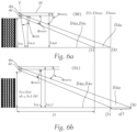
- Fig. 6a shows the ranges at altitude S0
- Fig. 6b that at altitude level S1, which is higher than level S0.
- the range D0 and D1 are lower in the zero level S0 than in the altitude level S1, namely by the difference ⁇ D.
- the upper projection device 4a can be switched off at height S1.
- the range D1 or the corresponding one Beam angle ⁇ maxc of the underlying projection device 4c is chosen so that the range D1 at the height S1 corresponds exactly to the range D max .
Landscapes
- Engineering & Computer Science (AREA)
- Mechanical Engineering (AREA)
- Physics & Mathematics (AREA)
- General Engineering & Computer Science (AREA)
- General Physics & Mathematics (AREA)
- Theoretical Computer Science (AREA)
- Mathematical Physics (AREA)
- Computer Hardware Design (AREA)
- Optics & Photonics (AREA)
- Microelectronics & Electronic Packaging (AREA)
- Multimedia (AREA)
- Signal Processing (AREA)
- Business, Economics & Management (AREA)
- Accounting & Taxation (AREA)
- Marketing (AREA)
- Lighting Device Outwards From Vehicle And Optical Signal (AREA)
Abstract
Description
- Die Erfindung betrifft ein Kraftfahrzeuglichtsystem zur Abstrahlung von positionsbegrenzten Bodenprojektionen für ein Kraftfahrzeug mit einem gestuft höhenverstellbaren Fahrwerk, wobei zumindest zwei vordefinierte Fahrwerk-Höhenstufen vorgesehen sind, nämlich eine Nullstufe und zumindest eine höher gelegene Betriebsstufe, wobei das Kraftfahrzeuglichtsystem Folgendes umfasst: Zumindest zwei Projektionsvorrichtungen, eine mit jeder Projektionsvorrichtungen verbundene Steuereinheit zur einzelnen Ansteuerung jeder Projektionsvorrichtung, wobei jede Projektionsvorrichtung zur Montage in oder an einem Kraftfahrzeug, insbesondere in oder an einem Türschweller des Kraftfahrzeugs, eingerichtet ist, wobei jede Projektionsvorrichtung weiters dazu eingerichtet ist, in einem an dem Kraftfahrzeug montierten und aktivierten Zustand genau eine Bodenprojektion ausgehend von einem unmittelbaren Nahbereich des Kraftfahrzeug auf einen seitlich umgebenden Boden bis hin zu einem maximalen flachen Grenzwinkel abzustrahlen, wobei sämtliche Projektionsvorrichtungen auf einem gemeinsam Träger befestigt und innerhalb einer gemeinsamen Ebene angeordnet sind und jeweils eine optische Achse aufweisen, wobei die optischen Achsen der Projektionsvorrichtungen zueinander parallel orientiert sind, wobei jede Projektionsvorrichtung ein Mikrolinsenprojektionsmodul ist, wobei jedes Mikrolinsenprojektionsmodul eine Lichtquelle, eine Eintrittsoptik, welche eine Gesamtanzahl von Mikro-Eintrittsoptiken aufweist, welche in einem Array angeordnet sind, wobei die Eintrittsoptik zum Empfang von der Lichtquelle abgestrahlten Licht eingerichtet ist, sowie eine Austrittsoptik, welche eine Gesamtanzahl von Mikro-Austrittsoptiken aufweist, welche in einem Array angeordnet sind, aufweist, wobei jeder Mikro-Eintrittsoptik genau eine Mikro-Austrittsoptik zugeordnet ist, wobei die Mikro-Eintrittsoptiken derart ausgebildet und/oder die Mikro-Eintrittsoptiken und die Mikro-Austrittsoptiken derart zueinander angeordnet sind, dass im Wesentlichen das gesamte aus einer Mikro-Eintrittsoptik austretende Licht nur in die zugeordnete Mikro-Austrittsoptik eintritt, und wobei das von den Mikro-Eintrittsoptiken vorgeformte Licht von den Mikro-Austrittsoptiken im montierten Zustand des Kraftfahrzeuglichtsystems in einen Bereich neben dem Kraftfahrzeug als besagte Bodenprojektion abbildbar ist, wobei zwischen der Mikro-Eintrittsoptik und der Mikro-Austrittsoptik zumindest eine Blendenvorrichtung angeordnet ist, wobei der Abstrahlwinkel jeder Projektionsvorrichtung im montierten Zustand hin zu einer horizontalen Ebene begrenzt ist, und zwar so, dass die Abstrahlung in Bezug auf die horizontale Ebene abwärts geneigt ist.
- Systeme zur Abstrahlung von Bodenprojektionen sind aus dem Stand der Technik bekannt geworden. Ebenso ist der Einsatz von Mikroprojektionslinsenmodulen bekannt, beispielsweise aus der
WO 2015/058227 A1 oder derWO 2019110374 A1 , die jeweils den Aufbau von Mikroprojektionslinsenmodulen zeigen, der auch für den Einsatz bei der vorliegenden Erfindung grundsätzlich geeignet ist. Etwas anders als bei diesen Modulen, die z.B. eine Abblendlichtverteilung erzeugen, bei der die Blendenkante sehr stark ausgeleuchtet wird und deshalb die Mikroeintrittsoptik darauf fokussiert wird, ist es bei der vorliegenden Erfindung allerdings möglich, dass kein Fokus auf die Kanten der Blendenöffnung erfolgt, sondern eine gleichmäßige Ausleuchtung der Öffnung erzielt wird, um im Idealfall eine gleichmäßige Ausleuchtung zu erreichen. Es kann sich also um eine sogenannte Köhler'sche Beleuchtung handeln, wobei, wie gesagt, der Brennpunkt der Mikroeintrittsoptik nicht zwingend auf der Blendenebene liegt, sondern zu dieser (nach vorne oder hinten gesehen in Lichtabstrahlrichtung) versetzt ist, um eine homogene Ausleuchtung über den gesamten Bereich der Blendenöffnung zu erzielen. - Ein Problem von Bodenprojektionsmodulen gemäß dem Stand der Technik besteht darin, dass im Falle des Einsatzes in Verbindung mit Fahrzeugen, die ein höhenverstellbares Fahrwerk aufweisen, Verzerrungen der abgestrahlten Bodenprojektion in Abhängigkeit von der Einstellung der Fahrwerkshöhe auftreten können.
- Eine Aufgabe der Erfindung besteht daher darin, diesen Nachteil des Standes der Technik zu beheben. Diese Aufgabe wird mit einem Kraftfahrzeuglichtsystem der eingangs genannten Art gelöst, bei welchem erfindungsgemäß die Steuereinheit eine Kommunikationsschnittstelle zum Empfang und zur Auswertung eines Fahrwerkssignals aufweist, wobei das Fahrwerkssignal Informationen zu dem Ist-Zustand der Fahrwerk-Höhenstufe enthält, wobei für jede Fahrwerk-Höhenstufe der Betrieb zumindest eine hierfür optimierten Projektionsvorrichtung vorgesehen ist, wobei sich für jede Projektionsvorrichtung, die für eine Fahrwerk-Höhenstufe optimiert ist, aufgrund der in der jeweiligen Fahrwerk-Höhenstufe vorliegenden Höhe sowie dem der jeweiligen Projektionsvorrichtung zugeordneten flachen Grenzwinkel eine Reichweitengrenze der Bodenprojektion ergibt, wobei die Optimierung der Projektionsvorrichtungen dergestalt implementiert ist, dass die für die jeweiligen Fahrwerk-Höhenstufen optimierten Projektionsvorrichtungen unterschiedliche flache Grenzwinkel aufweisen, und zwar so, dass die flachen Grenzwinkel der Projektionsvorrichtungen ausgehend von jener Projektionsvorrichtung, die für die Nullstufe optimiert ist, mit zunehmender Höhe der den Projektionsvorrichtungen zugeordneten Fahrwerk-Höhenstufen entsprechend der Höhendifferenz zur Nullstufe zunehmen, sodass für jede Fahrwerk-Höhenstufe zumindest eine Projektionsvorrichtung vorgesehen ist, deren Reichweitengrenze im Betrieb der Fahrwerk-Höhenstufe, für die die jeweilige Projektionsvorrichtung optimiert ist, mit der Reichweitengrenze der Projektionsvorrichtung für die Nullstufe übereinstimmt.
- Insbesondere kann vorgesehen sein, dass die Ansteuerung der Projektionsvorrichtungen durch die Steuereinheit dergestalt ausgebildet ist, dass der Betrieb jener Projektionsvorrichtungen deaktiviert wird, die für eine niedrigere Fahrwerk-Höhenstufe als der anhand des Fahrwerkssignals festgestellten vorliegenden Fahrwerk-Höhenstufe optimiert sind.
- Durch die Erfindung ist es möglich, dass die die Reichweitengrenze trotz Zunahme der relativen Höhe der Projektionsvorrichtungen nicht überschritten wird. Unter einer optischen Achse einer Projektionsvorrichtung wird jene Achse verstanden, entlang der die Abstrahlung von Eintrittsoptiken hin zu den Austrittsoptiken erfolgt. Die Abstrahlung selbst wird dann durch die Blenden beschnitten und dadurch in der räumlichen Ausrichtung beeinflusst.
- Weiters kann vorgesehen sein, dass die Ansteuerung der Projektionsvorrichtungen durch die Steuereinheit dergestalt ausgebildet ist, dass jene Projektionsvorrichtungen, die für einen Betrieb mit einer höheren Fahrwerk-Höhenstufe als der festgestellten vorliegenden Fahrwerk-Höhenstufe optimiert sind, weiterhin aktivierbar sind. Dadurch sind Überlagerungen der Bodenprojektionen möglich, ohne dass dabei die Reichweitengrenze überschritten wird.
- Insbesondere kann vorgesehen sein, dass die Ansteuerung der Projektionsvorrichtungen durch die Steuereinheit dergestalt ausgebildet ist, dass durch eine zeitliche Abfolge der Aktivierung von Projektionsvorrichtungen eine Animation projizierbar ist, wobei die zeitliche Abfolge der Aktivierung auch jene Projektionsvorrichtungen umfasst, die für einen Betrieb mit einer höheren Fahrwerk-Höhenstufe als der festgestellten vorliegenden Fahrwerk-Höhenstufe optimiert sind.
- Weiters kann vorgesehen sein, dass die Ansteuerung der Projektionsvorrichtungen durch die Steuereinheit dergestalt erfolgt, dass der Betrieb sämtlicher Projektionsvorrichtungen deaktiviert wird, die nicht für die festgestellte vorliegenden Fahrwerk-Höhenstufe optimiert sind. Die technische Lösung zeichnet sich durch eine besonders hohe Robustheit aus.
- Insbesondere kann vorgesehen sein, dass sich die Projektionsvorrichtungen, die für unterschiedliche Fahrwerk-Höhenstufen optimiert sind, durch die vorgesehene räumliche Positionierung an dem Kraftfahrzeug unterscheiden, und zwar so, dass mit Optimierung für abnehmende Höhe der Fahrwerk-Höhenstufen die Höhe der Montageposition der jeweiligen Projektionsvorrichtung zunimmt. Insbesondre kann vorgesehen sein, dass die unterste Projektionsvorrichtung den steilsten Winkel αmax aufweist, sodass bei zunehmender Höhenstufe die Projektionsvorrichtung von oben weg abgeschaltet werden, und damit immer ein maximal steiler Projektionswinkel garantiert ist, mit dem Verzerrungen minimiert werden können.
- Weiters kann vorgesehen sein, dass die Eintrittsoptiken und die Austrittsoptiken sämtlicher Projektionsvorrichtungen gleichartig ausgebildet sind, wobei sich die für die jeweiligen Fahrwerk-Höhenstufen optimierten Projektionsvorrichtungen in der Ausgestaltung der Blendenvorrichtungen voneinander unterscheiden.
- Insbesondere kann vorgesehen sein, dass sich die Projektionsvorrichtungen, die für unterschiedliche Fahrwerk-Höhenstufen optimiert sind, durch die Ausgestaltung von Blendenöffnungen voneinander unterscheiden, und zwar so, dass mit Optimierung für zunehmende Höhe der Fahrwerk-Höhenstufen die Größe der jeweilige Blendenöffnung abnimmt. Die Blendenöffnung wird dabei vorzugsweise dergestalt verkleinert, dass der maximale Ausleuchtbereich nicht überschritten wird. Unter einer kleineren Größe wird verstanden, dass die Fläche der Blendenöffnung geringer ist.
- Weiters kann vorgesehen sein, dass die Steuerungseinheit zur Regelung der Intensität der Abstrahlung zumindest jener Lichtquellen eingerichtet ist, die den Projektionsvorrichtungen ausgenommen der Projektionsvorrichtung der Nullstufe zugeordnet sind.
- Insbesondere kann vorgesehen sein, dass mit abnehmender Größe der Blendenöffnung die Nennleistung der Lichtquellen der entsprechenden Projektionsvorrichtungen erhöht ist, sodass die Lichtintensität der Lichtverteilungen, die von unterschiedlichen Projektionsvorrichtungen abgestrahlt wird, gleich ist. Das bedeutet, dass die durch die geringere Blendenöffnung verursachte geringere Lichtdurchlässigkeit kompensiert werden kann, sodass mit unterschiedlichen optimierten Projektionsvorrichtungen in der jeweiligen Fahrwerk-Höhenstufe auf der Projektionsfläche ein gleich heller Leuchteindruck entsteht.
- Weiters kann vorgesehen sein, dass drei oder mehr Fahrwerk-Höhenstufen vorgesehen sind.
- Insbesondere kann vorgesehen sein, dass die Differenz der Höhe der Nullstufe und der Höhe der höchsten Fahrwerk-Höhenstufe zwischen 1cm und 20cm beträgt und die Fahrwerk-Höhenstufen vorzugsweise gleichmäßig voneinander beabstandet sind. Beispielsweise kann die Spanne 13cm betragen, und sich über 3 Stufen erstrecken, wobei ausgehend von einer mittleren Stufe ein Hub von 55mm nach unten und 75mm nach oben möglich sein kann.
- Weiters kann vorgesehen sein, dass die Reichweitengrenze der Bodenprojektion im montierten Zustand des Kraftfahrzeuglichtsystem zwischen 0,5m und 3m, insbesondere zwischen 1m und 2m beträgt, wobei die Reichweitengrenze entlang eines ebenen Bodens in Normalabstand zur Längsachse des Fahrzeugs ausgehend von einer Normalprojektion des Schwellers des Kraftfahrzeugs bis zum Ende der Bodenprojektion gemessen wird.
- Insbesondere kann vorgesehen sein, dass die Projektionsvorrichtungen matrixartig auf dem gemeinsamen Träger angeordnet sind und zwischen benachbarten Projektionsvorrichtungen eine lichtundurchlässige Isolierung angeordnet ist.
- Weiters kann vorgesehen sein, dass Kraftfahrzeug, umfassend zumindest zwei Kraftfahrzeuglichtsysteme nach einem der vorhergehenden Ansprüche, wobei das Kraftfahrzeug eine linke und eine rechte Fahrzeugseite aufweist, und jede Fahrzeugseite zumindest eine Tür mit einer der Tür zugeordneten Schwelle aufweist, wobei in den Schwellen jeweils die Projektionsvorrichtungen angeordnet sind.
- Die Erfindung ist im Folgenden anhand einer beispielhaften und nicht einschränkenden Ausführungsform näher erläutert, die in den Figuren veranschaulicht ist. Darin zeigt
-
Figur 1 eine schematische Darstellung eines Fahrzeugs umfassend zwei erfindungsgemäße Kraftfahrzeuglichtsysteme, -
Figur 2 eine schematische Darstellung von Komponenten eines Kraftfahrzeuglichtsystems, -
Figur 3 eine beispielhafte Darstellung eines Mikrolinsenprojektionsmoduls, -
Figur 4 eine beispielhafte Anordnung einer Mikro-Eintrittsoptik, einer Mikro-Blende sowie einer Mikro-Austrittsoptik, -
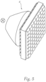
Figur 5 eine schematische Darstellung eines Mikrolinsenprojektionsmoduls im zusammengebauten Zustand, -
Figur 6a eine Darstellung der Abstrahlung von Bodenprojektionen im einer unteren Fahrwerks-Höhenstufe, und -
Figur 6b eine Darstellung der Abstrahlung von Bodenprojektionen im einer oberen Fahrwerks-Höhenstufe. - In den folgenden Figuren bezeichnen - sofern nicht anders angegeben - gleiche Bezugszeichen gleiche Merkmale.
-
Figur 1 zeigt eine schematische Darstellung eines Fahrzeugs 1 umfassend zwei erfindungsgemäße Kraftfahrzeuglichtsysteme 2. Das Kraftfahrzeug 1 umfasst zumindest zwei Kraftfahrzeuglichtsysteme 2, wobei das Kraftfahrzeug 1 eine linke und eine rechte Fahrzeugseite aufweist, und jede Fahrzeugseite zumindest eine Tür 7 mit einer der Tür 7 zugeordneten Schwelle 6 aufweist, wobei in den Schwellen jeweils die Projektionsvorrichtungen 4a, 4b, 4c, 4d angeordnet sind. - In
Figur 6a und 6b ist erkennbar, dass das Kraftfahrzeuglichtsystem 2 zur Abstrahlung von positionsbegrenzten Bodenprojektionen B4a, B4c eingerichtet ist. Das Kraftfahrzeug 1 weist dabei ein gestuft höhenverstellbares Fahrwerk 3 auf (sieheFig. 1 ), wobei zumindest zwei vordefinierte Fahrwerk-Höhenstufen S0, S1 (sieheFig. 6a und 6b ) vorgesehen sind, nämlich eine Nullstufe S0 und zumindest eine höher gelegene Betriebsstufe S1. Das Kraftfahrzeuglichtsystem 2 umfasst Folgendes: Zumindest zwei Projektionsvorrichtungen 4a, 4b, 4c, 4d (sieheFig. 2 ), eine mit jeder Projektionsvorrichtungen 4a, 4b, 4c, 4d verbundene Steuereinheit 5 zur einzelnen Ansteuerung jeder Projektionsvorrichtung 4a, 4b, 4c, 4d, wobei jede Projektionsvorrichtung 4a, 4b, 4c, 4d zur Montage in oder an einem Kraftfahrzeug 1, insbesondere in oder an einem Türschweller 6 des Kraftfahrzeugs 1, eingerichtet ist, wobei jede Projektionsvorrichtung 4a, 4b, 4c, 4d weiters dazu eingerichtet ist, in einem an dem Kraftfahrzeug 1 montierten und aktivierten Zustand genau eine Bodenprojektion B4a, B4c ausgehend von einem unmittelbaren Nahbereich αmin des Kraftfahrzeug 1 auf einen seitlich umgebenden Boden B bis hin zu einem maximalen flachen Grenzwinkel αmaxa, αmaxc abzustrahlen, wobei sämtliche Projektionsvorrichtungen 4a, 4b, 4c, 4d auf einem gemeinsam Träger 4' befestigt und innerhalb einer gemeinsamen Ebene E (sieheFig. 6a ) angeordnet sind und jeweils eine optische Achse A4a, A4c (sieheFig. 2 ) aufweisen, wobei die optischen Achsen A4a, A4c der Projektionsvorrichtungen zueinander parallel orientiert sind. Jede Projektionsvorrichtung 4a, 4b, 4c, 4d ist als ein Mikrolinsenprojektionsmodul 4 (sieheFig. 3 ) ausgebildet, wobei jedes Mikrolinsenprojektionsmodul 4 eine Lichtquelle 41, eine Eintrittsoptik 42, welche eine Gesamtanzahl von Mikro-Eintrittsoptiken 421 aufweist, welche in einem Array angeordnet sind, wobei die Eintrittsoptik 42 zum Empfang von der Lichtquelle 41 abgestrahlten Licht eingerichtet ist, sowie eine Austrittsoptik 43, welche eine Gesamtanzahl von Mikro-Austrittsoptiken 431 aufweist, welche in einem Array angeordnet sind, aufweist, wobei jeder Mikro-Eintrittsoptik 421 genau eine Mikro-Austrittsoptik 431 zugeordnet ist, wobei die Mikro-Eintrittsoptiken 421 derart ausgebildet und/oder die Mikro-Eintrittsoptiken 421 und die Mikro-Austrittsoptiken 431 derart zueinander angeordnet sind, dass im Wesentlichen das gesamte aus einer Mikro-Eintrittsoptik 421 austretende Licht nur in die zugeordnete Mikro-Austrittsoptik 431 eintritt, und wobei das von den Mikro-Eintrittsoptiken 421 vorgeformte Licht von den Mikro-Austrittsoptiken 431 im montierten Zustand des Kraftfahrzeuglichtsystems 2 in einen Bereich neben dem Kraftfahrzeug 1 als besagte Bodenprojektion B4a, B4c abbildbar ist, wobei zwischen der Mikro-Eintrittsoptik 421 und der Mikro-Austrittsoptik 431 zumindest eine Blendenvorrichtung 44 angeordnet ist, wobei der Abstrahlwinkel jeder Projektionsvorrichtung 4a, 4b, 4c, 4d im montierten Zustand hin zu einer horizontalen Ebene H (sieheFig. 6a ) begrenzt ist, und zwar so, dass die Abstrahlung in Bezug auf die horizontale Ebene H abwärts geneigt ist. - Die Steuereinheit 5 weist eine Kommunikationsschnittstelle 5a zum Empfang und zur Auswertung eines Fahrwerkssignals S auf, wobei das Fahrwerkssignal S Informationen zu dem Ist-Zustand der Fahrwerk-Höhenstufe S0, S1 enthält. Für jede Fahrwerk-Höhenstufe S0, S1 ist der Betrieb zumindest eine hierfür optimierten Projektionsvorrichtung 4a, 4b, 4c, 4d vorgesehen, wobei sich für jede Projektionsvorrichtung 4a, 4b, 4c, 4d, die für eine Fahrwerk-Höhenstufe S0, S1 optimiert ist, aufgrund der in der jeweiligen Fahrwerk-Höhenstufe S0, S1 vorliegenden Höhe h4c0, h4a0, h4c1, h4a1 sowie dem der jeweiligen Projektionsvorrichtung 4a, 4b, 4c, 4d zugeordneten flachen Grenzwinkel αmax_a, αmaxc eine Reichweitengrenze Dmax (siehe
Fig. 6a, 6b ) der Bodenprojektion B4a, B4c ergibt. - Die Optimierung der Projektionsvorrichtungen 4a, 4b, 4c, 4d ist dergestalt implementiert, dass die für die jeweiligen Fahrwerk-Höhenstufen S0, S1 optimierten Projektionsvorrichtungen 4a, 4b, 4c, 4d unterschiedliche flache Grenzwinkel αmaxa, αmaxc aufweisen, und zwar so, dass die flachen Grenzwinkel αmaxa, αmaxc der Projektionsvorrichtungen 4a, 4b, 4c, 4d ausgehend von jener Projektionsvorrichtung 4a, die für die Nullstufe S0 optimiert ist, mit zunehmender Höhe der den Projektionsvorrichtungen 4a, 4b, 4c, 4d zugeordneten Fahrwerk-Höhenstufen S0, S1 entsprechend der Höhendifferenz Δh (siehe
Fig. 6b ) zur Nullstufe S0 zunehmen, sodass für jede Fahrwerk-Höhenstufe S0, S1 zumindest eine Projektionsvorrichtung 4a, 4b, 4c, 4d vorgesehen ist, deren Reichweitengrenze D0, D1 im Betrieb der Fahrwerk-Höhenstufe S0, S1, für die die jeweilige Projektionsvorrichtung 4a, 4b, 4c, 4d optimiert ist, mit der Reichweitengrenze Dmax der Projektionsvorrichtung 4a, 4b, 4c, 4d für die Nullstufe S0 übereinstimmt. In dem vorliegend gezeigtem Ausführungsbeispiel sind nur zwei Höhenstufen S0 und S1 und nur zwei Abstrahlwinkel der Projektionsvorrichtungen gezeigt. Natürlich können auch mehrere Höhenstufen und Abstrahlwinkel bzw. Projektionsvorrichtungen vorgesehen sein, wobei jede Projektionsvorrichtung für eine Höhenstufe optimiert ist und jeder Höhenstufe zumindest eine hierfür optimierte Projektionsvorrichtung zugeordnet ist. - Es kann vorgesehen sein, dass die Ansteuerung der Projektionsvorrichtungen 4a, 4b, 4c, 4d durch die Steuereinheit 5 dergestalt ausgebildet ist, dass der Betrieb jener Projektionsvorrichtungen 4a, 4b, 4c, 4d deaktiviert wird, die für eine niedrigere Fahrwerk-Höhenstufe S0, S1 als der anhand des Fahrwerkssignals S festgestellten vorliegenden Fahrwerk-Höhenstufe S0, S1 optimiert sind. Dabei kann die Ansteuerung der Projektionsvorrichtungen 4a, 4b, 4c, 4d durch die Steuereinheit 5 dergestalt ausgebildet sein, dass jene Projektionsvorrichtungen 4a, 4b, 4c, 4d, die für einen Betrieb mit einer höheren Fahrwerk-Höhenstufe S1 als der festgestellten vorliegenden Fahrwerk-Höhenstufe S0 optimiert sind, weiterhin aktivierbar sind.
- Insbesondere kann vorgesehen sein, dass die Ansteuerung der Projektionsvorrichtungen 4a, 4b, 4c, 4d durch die Steuereinheit 5 dergestalt ausgebildet ist, dass durch eine zeitliche Abfolge der Aktivierung von Projektionsvorrichtungen 4a, 4b, 4c, 4d eine Animation projizierbar ist, wobei die zeitliche Abfolge der Aktivierung auch jene Projektionsvorrichtungen 4a, 4b, 4c, 4d umfasst, die für einen Betrieb mit einer höheren Fahrwerk-Höhenstufe S1 als der festgestellten vorliegenden Fahrwerk-Höhenstufe S0 optimiert sind.
- Alternativ dazu kann vorgesehen sein, dass die Ansteuerung der Projektionsvorrichtungen 4a, 4b, 4c, 4d durch die Steuereinheit 5 dergestalt erfolgt, dass der Betrieb sämtlicher Projektionsvorrichtungen 4a, 4b, 4c, 4d deaktiviert wird, die nicht für die festgestellte vorliegenden Fahrwerk-Höhenstufe S0, S1 optimiert sind.
- Weiters kann vorgesehen sein, dass sich die Projektionsvorrichtungen 4a, 4b, 4c, 4d, die für unterschiedliche Fahrwerk-Höhenstufen S0, S1 optimiert sind, durch die vorgesehene räumliche Positionierung an dem Kraftfahrzeug 1 unterscheiden, und zwar so, dass mit Optimierung für abnehmende Höhe der Fahrwerk-Höhenstufen S0, S1 die Höhe der Montageposition der jeweiligen Projektionsvorrichtung 4a, 4b, 4c, 4d zunimmt.
- In
Fig. 4 ist schematisch erkennbar, dass die Eintrittsoptiken 42 und die Austrittsoptiken 43 sämtlicher Projektionsvorrichtungen 4a, 4b, 4c, 4d gleichartig ausgebildet sein können, wobei sich die für die jeweiligen Fahrwerk-Höhenstufen S0, S1 optimierten Projektionsvorrichtungen 4a, 4b, 4c, 4d in der Ausgestaltung der Blendenvorrichtungen 8a', 8a", 8a‴ voneinander unterscheiden können um die unterschiedlichen Grenzwinkel zu realisieren. Insbesondere kann dabei vorgesehen sein, dass sich die Projektionsvorrichtungen 4a, 4b, 4c, 4d, die für unterschiedliche Fahrwerk-Höhenstufen S0, S1 optimiert sind, durch die Ausgestaltung von Blendenöffnungen 441' (sieheFig. 4 ) der Mikroblenden 441 voneinander unterscheiden, und zwar so, dass mit Optimierung für zunehmende Höhe der Fahrwerk-Höhenstufen S0, S1 die Größe der jeweilige Blendenöffnung 441' abnimmt. - Es kann vorgesehen sein, dass die Steuerungseinheit 5 zur Regelung der Intensität der Abstrahlung zumindest jener Lichtquellen 41 eingerichtet ist, die den Projektionsvorrichtungen 4c, 4d ausgenommen der Projektionsvorrichtung 4a, 4b der Nullstufe S0 zugeordnet sind. Vorteilhaft kann vorgesehen sein, dass mit abnehmender Größe der Blendenöffnung 441' die Nennleistung der Lichtquellen 41 der entsprechenden Projektionsvorrichtungen 4a, 4b, 4c, 4d erhöht ist, sodass die Lichtintensität der Lichtverteilungen, die von unterschiedlichen Projektionsvorrichtungen 4a, 4b, 4c, 4d abgestrahlt wird, gleich ist. Das bedeutet, dass die durch die geringere Blendenöffnung verursachte geringere Lichtdurchlässigkeit kompensiert wird, sodass mit unterschiedlichen optimierten Projektionsvorrichtungen in der jeweiligen Fahrwerk-Höhenstufe auf der Projektionsfläche ein gleich heller Leuchteindruck entsteht.
- Weiters kann vorgesehen sein, dass die Differenz der Höhe der Nullstufe S0 und der Höhe der höchsten Fahrwerk-Höhenstufe S1 zwischen 1cm und 20cm beträgt und die Fahrwerk-Höhenstufen S0, S1 vorzugsweise gleichmäßig voneinander beabstandet sind.
- Insbesondere kann vorgesehen sein, dass die Reichweitengrenze Dmax der Bodenprojektion im montierten Zustand des Kraftfahrzeuglichtsystem 2 zwischen 0,5m und 3m, insbesondere zwischen 1m und 2m beträgt, wobei die Reichweitengrenze Dmax entlang eines ebenen Bodens B in Normalabstand zur Längsachse x des Fahrzeugs 1 ausgehend von einer Normalprojektion des Schwellers 6 des Kraftfahrzeugs bis zum Ende der Bodenprojektion B4a, B4c gemessen wird.
- Zudem kann vorgesehen sein, dass die Projektionsvorrichtungen 4a, 4b, 4c, 4d matrixartig auf dem gemeinsamen Träger 4' (siehe
Fig. 2 ) angeordnet sind und zwischen benachbarten Projektionsvorrichtungen 4a, 4b, 4c, 4d eine lichtundurchlässige Isolierung 4" angeordnet ist. - Mit Blick auf
Fig. 6a und Fig. 6b sei erwähnt, dass darin die Reichweiten der Vorrichtungen 4a und 4c beispielhaft gezeigt sind, die sich in Abhängigkeit von der Fahrwerk-Höhenstufe bestimmt.Fig. 6a zeigt die Reichweiten in der Höhenstufe S0,Fig. 6b jene in der Höhenstufe S1, die gegenüber der Stufe S0 erhöht ist. Die Reichweite D0 und D1 sind in der Nullstufe S0 niedriger als in der Höhenstufe S1, und zwar um die Differenz ΔD. Um eine maximale Reichweitengrenze Dmax nicht zu überschreiten, kann daher die obere Projektionsvorrichtung 4a in der Höhe S1 abgeschaltet werden. Die Reichweite D1 bzw. der dazu korrespondierende Abstrahlwinkel αmaxc der darunter liegenden Projektionsvorrichtung 4c ist dabei so gewählt, dass die Reichweite D1 in der Höhe S1 genau mit der Reichweite Dmax übereinstimmt. Durch gezieltes Zu- und Wegschalten einzelner Projektionsvorrichtungen in Abhängigkeit von der Fahrwerks-Höhenstufe kann daher die Bodenprojektion weitgehend konstant gehalten werden und sichergestellt werden, dass die Grenzen, insbesondere die maximale Reichweite der Bodenprojektion Dmax nicht überschritten werden. - Die Erfindung ist nicht auf die gezeigten Ausführungsformen beschränkt, sondern durch den gesamten Schutzumfang der Ansprüche definiert. Auch können einzelne Aspekte der Erfindung bzw. der Ausführungsformen aufgegriffen und miteinander kombiniert werden. Etwaige Bezugszeichen in den Ansprüchen sind beispielhaft und dienen nur der einfacheren Lesbarkeit der Ansprüche, ohne diese einzuschränken.
Claims (15)
- Kraftfahrzeuglichtsystem (2) zur Abstrahlung von positionsbegrenzten Bodenprojektionen (B4a, B4c) für ein Kraftfahrzeug (1) mit einem gestuft höhenverstellbaren Fahrwerk (3), wobei zumindest zwei vordefinierte Fahrwerk-Höhenstufen (S0, S1) vorgesehen sind, nämlich eine Nullstufe (S0) und zumindest eine höher gelegene Betriebsstufe (S1), wobei das Kraftfahrzeuglichtsystem (2) Folgendes umfasst:- zumindest zwei Projektionsvorrichtungen (4a, 4b, 4c, 4d),- eine mit jeder Projektionsvorrichtungen (4a, 4b, 4c, 4d) verbundene Steuereinheit (5) zur einzelnen Ansteuerung jeder Projektionsvorrichtung (4a, 4b, 4c, 4d),wobei jede Projektionsvorrichtung (4a, 4b, 4c, 4d) zur Montage in oder an einem Kraftfahrzeug, insbesondere in oder an einem Türschweller (6) des Kraftfahrzeugs (1), eingerichtet ist, wobei jede Projektionsvorrichtung (4a, 4b, 4c, 4d) weiters dazu eingerichtet ist, in einem an dem Kraftfahrzeug (1) montierten und aktivierten Zustand genau eine Bodenprojektion (B4a, B4c) ausgehend von einem unmittelbaren Nahbereich (αmin) des Kraftfahrzeug (1) auf einen seitlich umgebenden Boden (B) bis hin zu einem maximalen flachen Grenzwinkel (αmax_a, αmaxc) abzustrahlen, wobei sämtliche Projektionsvorrichtungen (4a, 4b, 4c, 4d) auf einem gemeinsam Träger (4') befestigt und innerhalb einer gemeinsamen Ebene (E) angeordnet sind und jeweils eine optische Achse aufweisen, wobei die optischen Achsen der Projektionsvorrichtungen zueinander parallel orientiert sind, wobei jede Projektionsvorrichtung (4a, 4b, 4c, 4d) ein Mikrolinsenprojektionsmodul (4) ist, wobei jedes Mikrolinsenprojektionsmodul (4)*eine Lichtquelle (41),*eine Eintrittsoptik (42), welche eine Gesamtanzahl von Mikro-Eintrittsoptiken (421) aufweist, welche in einem Array angeordnet sind, wobei die Eintrittsoptik (42) zum Empfang von der Lichtquelle (41) abgestrahlten Licht eingerichtet ist,*sowie eine Austrittsoptik (43), welche eine Gesamtanzahl von Mikro-Austrittsoptiken (431) aufweist, welche in einem Array angeordnet sind, aufweist,wobei jeder Mikro-Eintrittsoptik (421) genau eine Mikro-Austrittsoptik (431) zugeordnet ist, wobei die Mikro-Eintrittsoptiken (421) derart ausgebildet und/oder die Mikro-Eintrittsoptiken (421) und die Mikro-Austrittsoptiken (431) derart zueinander angeordnet sind, dass im Wesentlichen das gesamte aus einer Mikro-Eintrittsoptik (421) austretende Licht nur in die zugeordnete Mikro-Austrittsoptik (431) eintritt, und wobei das von den Mikro-Eintrittsoptiken (421) vorgeformte Licht von den Mikro-Austrittsoptiken (431) im montierten Zustand des Kraftfahrzeuglichtsystems (2) in einen Bereich neben dem Kraftfahrzeug (1) als besagte Bodenprojektion (B4a, B4c) abbildbar ist, wobei zwischen der Mikro-Eintrittsoptik (421) und der Mikro-Austrittsoptik (431) zumindest eine Blendenvorrichtung (44) angeordnet ist, wobei der Abstrahlwinkel jeder Projektionsvorrichtung (4a, 4b, 4c, 4d) im montierten Zustand hin zu einer horizontalen Ebene (H) begrenzt ist, und zwar so, dass die Abstrahlung in Bezug auf die horizontale Ebene (H) abwärts geneigt ist,dadurch gekennzeichnet, dass die Steuereinheit (5) eine Kommunikationsschnittstelle (5a) zum Empfang und zur Auswertung eines Fahrwerkssignals (S) aufweist, wobei das Fahrwerkssignal (S) Informationen zu dem Ist-Zustand der Fahrwerk-Höhenstufe (S0, S1) enthält,wobei für jede Fahrwerk-Höhenstufe (S0, S1) der Betrieb zumindest eine hierfür optimierten Projektionsvorrichtung (4a, 4b, 4c, 4d) vorgesehen ist, wobei sich für jede Projektionsvorrichtung (4a, 4b, 4c, 4d), die für eine Fahrwerk-Höhenstufe (S0, S1) optimiert ist, aufgrund der in der jeweiligen Fahrwerk-Höhenstufe (S0, S1) vorliegenden Höhe (h4c0, h4a0, h4c1, h4a1) sowie dem der jeweiligen Projektionsvorrichtung (4a, 4b, 4c, 4d) zugeordneten flachen Grenzwinkel (αmax_a, αmaxc) eine Reichweitengrenze (D_max) der Bodenprojektion (B4a, B4c) ergibt,wobei die Optimierung der Projektionsvorrichtungen (4a, 4b, 4c, 4d) dergestalt implementiert ist, dass die für die jeweiligen Fahrwerk-Höhenstufen (S0, S1) optimierten Projektionsvorrichtungen (4a, 4b, 4c, 4d) unterschiedliche flache Grenzwinkel (αmax_a, αmaxc) aufweisen, und zwar so, dass die flachen Grenzwinkel (αmax_a, αmaxc) der Projektionsvorrichtungen (4a, 4b, 4c, 4d) ausgehend von jener Projektionsvorrichtung (4a), die für die Nullstufe (S0) optimiert ist, mit zunehmender Höhe der den Projektionsvorrichtungen (4a, 4b, 4c, 4d) zugeordneten Fahrwerk-Höhenstufen (S0, S1) entsprechend der Höhendifferenz (Δh) zur Nullstufe (S0) zunehmen, sodass für jede Fahrwerk-Höhenstufe (S0, S1) zumindest eine Projektionsvorrichtung (4a, 4b, 4c, 4d) vorgesehen ist, deren Reichweitengrenze (D0, D1) im Betrieb der Fahrwerk-Höhenstufe (S0, S1), für die die jeweilige Projektionsvorrichtung (4a, 4b, 4c, 4d) optimiert ist, mit der Reichweitengrenze (D_max) der Projektionsvorrichtung (4a, 4b, 4c, 4d) für die Nullstufe (S0) übereinstimmt.
- Kraftfahrzeuglichtsystem (2) nach Anspruch 1, wobei die Ansteuerung der Projektionsvorrichtungen (4a, 4b, 4c, 4d) durch die Steuereinheit (5) dergestalt ausgebildet ist, dass der Betrieb jener Projektionsvorrichtungen (4a, 4b, 4c, 4d) deaktiviert wird, die für eine niedrigere Fahrwerk-Höhenstufe (S0, S1) als der anhand des Fahrwerkssignals (S) festgestellten vorliegenden Fahrwerk-Höhenstufe (S0, S1) optimiert sind.
- Kraftfahrzeuglichtsystem (2) nach Anspruch 2, wobei die Ansteuerung der Projektionsvorrichtungen (4a, 4b, 4c, 4d) durch die Steuereinheit (5) dergestalt ausgebildet ist, dass jene Projektionsvorrichtungen (4a, 4b, 4c, 4d), die für einen Betrieb mit einer höheren Fahrwerk-Höhenstufe (S1) als der festgestellten vorliegenden Fahrwerk-Höhenstufe (S0) optimiert sind, weiterhin aktivierbar sind.
- Kraftfahrzeuglichtsystem (2) nach Anspruch 3, wobei die Ansteuerung der Projektionsvorrichtungen (4a, 4b, 4c, 4d) durch die Steuereinheit (5) dergestalt ausgebildet ist, dass durch eine zeitliche Abfolge der Aktivierung von Projektionsvorrichtungen (4a, 4b, 4c, 4d) eine Animation projizierbar ist, wobei die zeitliche Abfolge der Aktivierung auch jene Projektionsvorrichtungen (4a, 4b, 4c, 4d) umfasst, die für einen Betrieb mit einer höheren Fahrwerk-Höhenstufe (S1) als der festgestellten vorliegenden Fahrwerk-Höhenstufe (S0) optimiert sind.
- Kraftfahrzeuglichtsystem (2) nach Anspruch 2, wobei die Ansteuerung der Projektionsvorrichtungen (4a, 4b, 4c, 4d) durch die Steuereinheit (5) dergestalt erfolgt, dass der Betrieb sämtlicher Projektionsvorrichtungen (4a, 4b, 4c, 4d) deaktiviert wird, die nicht für die festgestellte vorliegenden Fahrwerk-Höhenstufe (S0, S1) optimiert sind.
- Kraftfahrzeuglichtsystem (2) nach einem der vorhergehenden Ansprüche, wobei sich die Projektionsvorrichtungen (4a, 4b, 4c, 4d), die für unterschiedliche Fahrwerk-Höhenstufen (S0, S1) optimiert sind, durch die vorgesehene räumliche Positionierung an dem Kraftfahrzeug (1) unterscheiden, und zwar so, dass mit Optimierung für abnehmende Höhe der Fahrwerk-Höhenstufen (S0, S1) die Höhe der Montageposition der jeweiligen Projektionsvorrichtung (4a, 4b, 4c, 4d) zunimmt.
- Kraftfahrzeuglichtsystem (2) nach einem der vorhergehenden Ansprüche, wobei die Eintrittsoptiken (42) und die Austrittsoptiken (43) sämtlicher Projektionsvorrichtungen (4a, 4b, 4c, 4d) gleichartig ausgebildet sind, wobei sich die für die jeweiligen Fahrwerk-Höhenstufen (S0, S1) optimierten Projektionsvorrichtungen (4a, 4b, 4c, 4d) in der Ausgestaltung der Blendenvorrichtungen (8a', 8a", 8a‴) voneinander unterscheiden.
- Kraftfahrzeuglichtsystem (2) nach Anspruch 7, wobei sich die Projektionsvorrichtungen (4a, 4b, 4c, 4d), die für unterschiedliche Fahrwerk-Höhenstufen (S0, S1) optimiert sind, durch die Ausgestaltung von Blendenöffnungen (441') voneinander unterscheiden, und zwar so, dass mit Optimierung für zunehmende Höhe der Fahrwerk-Höhenstufen (S0, S1) die Größe der jeweilige Blendenöffnung (441') abnimmt.
- Kraftfahrzeuglichtsystem (2) nach einem der vorhergehenden Ansprüche, wobei die Steuerungseinheit (5) zur Regelung der Intensität der Abstrahlung zumindest jener Lichtquellen (41) eingerichtet ist, die den Projektionsvorrichtungen (4c, 4d) ausgenommen der Projektionsvorrichtung (4a, 4b) der Nullstufe (S0) zugeordnet sind.
- Kraftfahrzeuglichtsystem (2) nach Anspruch 8 und 9, wobei mit abnehmender Größe der Blendenöffnung (441') die Nennleistung der Lichtquellen (41) der entsprechenden Projektionsvorrichtungen (4a, 4b, 4c, 4d) erhöht ist, sodass die Lichtintensität der Lichtverteilungen, die von unterschiedlichen Projektionsvorrichtungen (4a, 4b, 4c, 4d) abgestrahlt wird, gleich ist.
- Kraftfahrzeuglichtsystem (2) nach einem der vorhergehenden Ansprüche, wobei drei oder mehr Fahrwerk-Höhenstufen (S0, S1) vorgesehen sind.
- Kraftfahrzeuglichtsystem (2) nach einem der vorhergehenden Ansprüche, wobei die Differenz der Höhe der Nullstufe (S0) und der Höhe der höchsten Fahrwerk-Höhenstufe (S1) zwischen 1cm und 20cm beträgt und die Fahrwerk-Höhenstufen (S0, S1) vorzugsweise gleichmäßig voneinander beabstandet sind.
- Kraftfahrzeuglichtsystem (2) nach einem der vorhergehenden Ansprüche, wobei die Reichweitengrenze (D_max) der Bodenprojektion im montierten Zustand des Kraftfahrzeuglichtsystem (2) zwischen 0,5m und 3m, insbesondere zwischen 1m und 2m beträgt, wobei die Reichweitengrenze (D_max) entlang eines ebenen Bodens (B) in Normalabstand zur Längsachse (x) des Fahrzeugs (1) ausgehend von einer Normalprojektion des Schwellers (6) des Kraftfahrzeugs bis zum Ende der Bodenprojektion (B4a, B4c) gemessen wird.
- Kraftfahrzeuglichtsystem (2) nach einem der vorhergehenden Ansprüche, wobei die Projektionsvorrichtungen (4a, 4b, 4c, 4d) matrixartig auf dem gemeinsamen Träger (4') angeordnet sind und zwischen benachbarten Projektionsvorrichtungen (4a, 4b, 4c, 4d) eine lichtundurchlässige Isolierung (4") angeordnet ist.
- Kraftfahrzeug (1), umfassend zumindest zwei Kraftfahrzeuglichtsysteme (2) nach einem der vorhergehenden Ansprüche, wobei das Kraftfahrzeug (1) eine linke und eine rechte Fahrzeugseite aufweist, und jede Fahrzeugseite zumindest eine Tür (7) mit einer der Tür (7) zugeordneten Schwelle (6) aufweist, wobei in den Schwellen jeweils die Projektionsvorrichtungen (4a, 4b, 4c, 4d) angeordnet sind.
Priority Applications (3)
| Application Number | Priority Date | Filing Date | Title |
|---|---|---|---|
| EP22188112.1A EP4316911B1 (de) | 2022-08-01 | 2022-08-01 | Kraftfahrzeuglichtsystem zur abstrahlung von positionsbegrenzten bodenprojektionen |
| US18/225,817 US12139065B2 (en) | 2022-08-01 | 2023-07-25 | Motor vehicle lighting system for emitting position-limited ground projections |
| CN202310952635.0A CN117496847B (zh) | 2022-08-01 | 2023-07-31 | 用于放射位置受限的地面投影的机动车照明系统 |
Applications Claiming Priority (1)
| Application Number | Priority Date | Filing Date | Title |
|---|---|---|---|
| EP22188112.1A EP4316911B1 (de) | 2022-08-01 | 2022-08-01 | Kraftfahrzeuglichtsystem zur abstrahlung von positionsbegrenzten bodenprojektionen |
Publications (2)
| Publication Number | Publication Date |
|---|---|
| EP4316911A1 true EP4316911A1 (de) | 2024-02-07 |
| EP4316911B1 EP4316911B1 (de) | 2025-02-26 |
Family
ID=82786789
Family Applications (1)
| Application Number | Title | Priority Date | Filing Date |
|---|---|---|---|
| EP22188112.1A Active EP4316911B1 (de) | 2022-08-01 | 2022-08-01 | Kraftfahrzeuglichtsystem zur abstrahlung von positionsbegrenzten bodenprojektionen |
Country Status (3)
| Country | Link |
|---|---|
| US (1) | US12139065B2 (de) |
| EP (1) | EP4316911B1 (de) |
| CN (1) | CN117496847B (de) |
Cited By (1)
| Publication number | Priority date | Publication date | Assignee | Title |
|---|---|---|---|---|
| DE102025126957B3 (de) | 2025-07-09 | 2026-08-06 | Audi Aktiengesellschaft | Kraftfahrzeug |
Citations (10)
| Publication number | Priority date | Publication date | Assignee | Title |
|---|---|---|---|---|
| EP1203695A2 (de) * | 2000-11-04 | 2002-05-08 | Hella KG Hueck & Co. | Verfahren und Vorrichtung zur Leuchtweitenregelung der Scheinwerfer eines Kraftfahrzeuges |
| EP1916154A1 (de) * | 2006-10-26 | 2008-04-30 | Bayerische Motoren Werke Aktiengesellschaft | Verfahren zur Informationsdarstellung |
| DE202014101755U1 (de) * | 2013-04-26 | 2014-07-17 | Ford Global Technologies, Llc | Fahrzeugumfeldbeleuchtungsanordnung, die ein animiertes Bild erzeugt |
| WO2015032795A2 (en) * | 2013-09-03 | 2015-03-12 | Jaguar Land Rover Limited | System for imaging |
| WO2015058227A1 (de) | 2013-10-25 | 2015-04-30 | Zizala Lichtsysteme Gmbh | Mikroprojektions-lichtmodul für einen kraftfahrzeugscheinwerfer |
| DE102014210500A1 (de) * | 2014-06-03 | 2015-12-03 | Osram Gmbh | Optik für eine Fahrzeug-Beleuchtungseinrichtung |
| WO2019110374A1 (de) | 2017-12-05 | 2019-06-13 | Zkw Group Gmbh | Projektionseinrichtung für einen kraftfahrzeugscheinwerfer |
| DE102018203875A1 (de) * | 2018-03-14 | 2019-09-19 | Bayerische Motoren Werke Aktiengesellschaft | Kraftfahrzeug |
| US20190322209A1 (en) * | 2018-04-18 | 2019-10-24 | Maxell, Ltd. | Road sign projector and vehicle lamp |
| EP3608585A1 (de) * | 2018-08-07 | 2020-02-12 | ZKW Group GmbH | Projektionseinrichtung aus einer vielzahl von mikro-optiksystemen und ein lichtmodul für einen kraftfahrzeugscheinwerfer |
Family Cites Families (3)
| Publication number | Priority date | Publication date | Assignee | Title |
|---|---|---|---|---|
| JP4193595B2 (ja) * | 2003-06-06 | 2008-12-10 | ソニー株式会社 | 投射型表示装置 |
| US10493904B2 (en) * | 2017-07-17 | 2019-12-03 | Ford Global Technologies, Llc | Vehicle light assembly |
| US11703202B2 (en) * | 2021-08-10 | 2023-07-18 | ams OSRAM Automotive Lighting Systems USA Inc. | Image projection lighting assembly |
-
2022
- 2022-08-01 EP EP22188112.1A patent/EP4316911B1/de active Active
-
2023
- 2023-07-25 US US18/225,817 patent/US12139065B2/en active Active
- 2023-07-31 CN CN202310952635.0A patent/CN117496847B/zh active Active
Patent Citations (10)
| Publication number | Priority date | Publication date | Assignee | Title |
|---|---|---|---|---|
| EP1203695A2 (de) * | 2000-11-04 | 2002-05-08 | Hella KG Hueck & Co. | Verfahren und Vorrichtung zur Leuchtweitenregelung der Scheinwerfer eines Kraftfahrzeuges |
| EP1916154A1 (de) * | 2006-10-26 | 2008-04-30 | Bayerische Motoren Werke Aktiengesellschaft | Verfahren zur Informationsdarstellung |
| DE202014101755U1 (de) * | 2013-04-26 | 2014-07-17 | Ford Global Technologies, Llc | Fahrzeugumfeldbeleuchtungsanordnung, die ein animiertes Bild erzeugt |
| WO2015032795A2 (en) * | 2013-09-03 | 2015-03-12 | Jaguar Land Rover Limited | System for imaging |
| WO2015058227A1 (de) | 2013-10-25 | 2015-04-30 | Zizala Lichtsysteme Gmbh | Mikroprojektions-lichtmodul für einen kraftfahrzeugscheinwerfer |
| DE102014210500A1 (de) * | 2014-06-03 | 2015-12-03 | Osram Gmbh | Optik für eine Fahrzeug-Beleuchtungseinrichtung |
| WO2019110374A1 (de) | 2017-12-05 | 2019-06-13 | Zkw Group Gmbh | Projektionseinrichtung für einen kraftfahrzeugscheinwerfer |
| DE102018203875A1 (de) * | 2018-03-14 | 2019-09-19 | Bayerische Motoren Werke Aktiengesellschaft | Kraftfahrzeug |
| US20190322209A1 (en) * | 2018-04-18 | 2019-10-24 | Maxell, Ltd. | Road sign projector and vehicle lamp |
| EP3608585A1 (de) * | 2018-08-07 | 2020-02-12 | ZKW Group GmbH | Projektionseinrichtung aus einer vielzahl von mikro-optiksystemen und ein lichtmodul für einen kraftfahrzeugscheinwerfer |
Cited By (1)
| Publication number | Priority date | Publication date | Assignee | Title |
|---|---|---|---|---|
| DE102025126957B3 (de) | 2025-07-09 | 2026-08-06 | Audi Aktiengesellschaft | Kraftfahrzeug |
Also Published As
| Publication number | Publication date |
|---|---|
| US12139065B2 (en) | 2024-11-12 |
| CN117496847B (zh) | 2026-06-23 |
| US20240034223A1 (en) | 2024-02-01 |
| CN117496847A (zh) | 2024-02-02 |
| EP4316911B1 (de) | 2025-02-26 |
Similar Documents
| Publication | Publication Date | Title |
|---|---|---|
| DE102014001201B4 (de) | Beleuchtungsvorrichtung für ein Kraftfahrzeug mit zwei Typen von Leuchteinrichtungen | |
| DE102008036192A1 (de) | Kraftfahrzeugbeleuchtungseinrichtung | |
| DE102016102263B4 (de) | Lichtgerät, insbesondere ein Scheinwerfer für Kraftfahrzeuge | |
| EP2834554A1 (de) | Beleuchtungsvorrichtung für ein kraftfahrzeug | |
| EP3060842B1 (de) | Mikroprojektions-lichtmodul für einen kraftfahrzeugscheinwerfer | |
| EP2799761A2 (de) | Lichtmodul für einen Kraftfahrzeugscheinwerfer | |
| DE102016107252B4 (de) | Beleuchtungsvorrichtung für einen Fahrzeugscheinwerfer | |
| EP2477845A1 (de) | Fahrzeugscheinwerfer | |
| WO2019158319A1 (de) | Kraftfahrzeugscheinwerfer mit einer abschirmblende zur abschirmung eintretender sonnenstrahlung | |
| EP2984397B1 (de) | Leuchteinheit für einen fahrzeugscheinwerfer | |
| WO2011117217A1 (de) | Optisches anzeigeelement sowie anzeigevorrichtung | |
| DE102017204097A1 (de) | Optik, beleuchtungssystem und scheinwerfer | |
| EP3388734A1 (de) | Primäroptikeinheit für lichtmodul eines kfz-scheinwerfers | |
| EP3571437B1 (de) | Leuchtvorrichtung für einen kraftfahrzeugscheinwerfer | |
| DE102018203875A1 (de) | Kraftfahrzeug | |
| EP1338845B1 (de) | Leuchte | |
| EP4316911B1 (de) | Kraftfahrzeuglichtsystem zur abstrahlung von positionsbegrenzten bodenprojektionen | |
| DE102014016332A1 (de) | Scheinwerfer für ein Kraftfahrzeug und Verfahren zum Betreiben eines Scheinwerfers | |
| EP3218645A1 (de) | Einzelscheinwerfer für ein kraftfahrzeug | |
| EP0040853B1 (de) | Signalleuchte | |
| EP4202289B1 (de) | Optiksystem für einen kraftfahrzeugscheinwerfer | |
| WO2018114558A1 (de) | System, verfahren, computerprogrammprodukt und computerlesbares medium zur lichtformung für eine fahrzeugaussenleuchte | |
| DE102011002260A1 (de) | Adaptive Beleuchtungsvorrichtung | |
| EP1643473B1 (de) | Optisches Element für Wechselverkehrszeichen | |
| DE202013101038U1 (de) | Fahrzeuginnenleuchte |
Legal Events
| Date | Code | Title | Description |
|---|---|---|---|
| PUAI | Public reference made under article 153(3) epc to a published international application that has entered the european phase |
Free format text: ORIGINAL CODE: 0009012 |
|
| STAA | Information on the status of an ep patent application or granted ep patent |
Free format text: STATUS: THE APPLICATION HAS BEEN PUBLISHED |
|
| AK | Designated contracting states |
Kind code of ref document: A1 Designated state(s): AL AT BE BG CH CY CZ DE DK EE ES FI FR GB GR HR HU IE IS IT LI LT LU LV MC MK MT NL NO PL PT RO RS SE SI SK SM TR |
|
| STAA | Information on the status of an ep patent application or granted ep patent |
Free format text: STATUS: REQUEST FOR EXAMINATION WAS MADE |
|
| 17P | Request for examination filed |
Effective date: 20240725 |
|
| RBV | Designated contracting states (corrected) |
Designated state(s): AL AT BE BG CH CY CZ DE DK EE ES FI FR GB GR HR HU IE IS IT LI LT LU LV MC MK MT NL NO PL PT RO RS SE SI SK SM TR |
|
| RIC1 | Information provided on ipc code assigned before grant |
Ipc: F21S 41/663 20180101ALI20241122BHEP Ipc: F21S 41/43 20180101ALI20241122BHEP Ipc: F21S 41/40 20180101ALI20241122BHEP Ipc: F21S 41/20 20180101ALI20241122BHEP Ipc: F21S 41/265 20180101ALI20241122BHEP Ipc: F21S 41/255 20180101ALI20241122BHEP Ipc: F21S 41/25 20180101ALI20241122BHEP Ipc: F21S 41/153 20180101ALI20241122BHEP Ipc: F21S 41/151 20180101ALI20241122BHEP Ipc: B60Q 1/32 20060101ALI20241122BHEP Ipc: B60Q 1/24 20060101ALI20241122BHEP Ipc: B60Q 1/10 20060101AFI20241122BHEP |
|
| GRAP | Despatch of communication of intention to grant a patent |
Free format text: ORIGINAL CODE: EPIDOSNIGR1 |
|
| STAA | Information on the status of an ep patent application or granted ep patent |
Free format text: STATUS: GRANT OF PATENT IS INTENDED |
|
| GRAS | Grant fee paid |
Free format text: ORIGINAL CODE: EPIDOSNIGR3 |
|
| GRAA | (expected) grant |
Free format text: ORIGINAL CODE: 0009210 |
|
| STAA | Information on the status of an ep patent application or granted ep patent |
Free format text: STATUS: THE PATENT HAS BEEN GRANTED |
|
| INTG | Intention to grant announced |
Effective date: 20250103 |
|
| AK | Designated contracting states |
Kind code of ref document: B1 Designated state(s): AL AT BE BG CH CY CZ DE DK EE ES FI FR GB GR HR HU IE IS IT LI LT LU LV MC MK MT NL NO PL PT RO RS SE SI SK SM TR |
|
| REG | Reference to a national code |
Ref country code: GB Ref legal event code: FG4D Free format text: NOT ENGLISH |
|
| REG | Reference to a national code |
Ref country code: CH Ref legal event code: EP |
|
| REG | Reference to a national code |
Ref country code: DE Ref legal event code: R096 Ref document number: 502022003008 Country of ref document: DE |
|
| REG | Reference to a national code |
Ref country code: IE Ref legal event code: FG4D Free format text: LANGUAGE OF EP DOCUMENT: GERMAN |
|
| P01 | Opt-out of the competence of the unified patent court (upc) registered |
Free format text: CASE NUMBER: APP_14112/2025 Effective date: 20250321 |
|
| REG | Reference to a national code |
Ref country code: NL Ref legal event code: MP Effective date: 20250226 |
|
| PG25 | Lapsed in a contracting state [announced via postgrant information from national office to epo] |
Ref country code: RS Free format text: LAPSE BECAUSE OF FAILURE TO SUBMIT A TRANSLATION OF THE DESCRIPTION OR TO PAY THE FEE WITHIN THE PRESCRIBED TIME-LIMIT Effective date: 20250526 |
|
| PG25 | Lapsed in a contracting state [announced via postgrant information from national office to epo] |
Ref country code: FI Free format text: LAPSE BECAUSE OF FAILURE TO SUBMIT A TRANSLATION OF THE DESCRIPTION OR TO PAY THE FEE WITHIN THE PRESCRIBED TIME-LIMIT Effective date: 20250226 |
|
| PG25 | Lapsed in a contracting state [announced via postgrant information from national office to epo] |
Ref country code: PL Free format text: LAPSE BECAUSE OF FAILURE TO SUBMIT A TRANSLATION OF THE DESCRIPTION OR TO PAY THE FEE WITHIN THE PRESCRIBED TIME-LIMIT Effective date: 20250226 |
|
| PG25 | Lapsed in a contracting state [announced via postgrant information from national office to epo] |
Ref country code: ES Free format text: LAPSE BECAUSE OF FAILURE TO SUBMIT A TRANSLATION OF THE DESCRIPTION OR TO PAY THE FEE WITHIN THE PRESCRIBED TIME-LIMIT Effective date: 20250226 |
|
| REG | Reference to a national code |
Ref country code: LT Ref legal event code: MG9D |
|
| PG25 | Lapsed in a contracting state [announced via postgrant information from national office to epo] |
Ref country code: NO Free format text: LAPSE BECAUSE OF FAILURE TO SUBMIT A TRANSLATION OF THE DESCRIPTION OR TO PAY THE FEE WITHIN THE PRESCRIBED TIME-LIMIT Effective date: 20250526 Ref country code: IS Free format text: LAPSE BECAUSE OF FAILURE TO SUBMIT A TRANSLATION OF THE DESCRIPTION OR TO PAY THE FEE WITHIN THE PRESCRIBED TIME-LIMIT Effective date: 20250626 |
|
| PG25 | Lapsed in a contracting state [announced via postgrant information from national office to epo] |
Ref country code: NL Free format text: LAPSE BECAUSE OF FAILURE TO SUBMIT A TRANSLATION OF THE DESCRIPTION OR TO PAY THE FEE WITHIN THE PRESCRIBED TIME-LIMIT Effective date: 20250226 |
|
| PG25 | Lapsed in a contracting state [announced via postgrant information from national office to epo] |
Ref country code: HR Free format text: LAPSE BECAUSE OF FAILURE TO SUBMIT A TRANSLATION OF THE DESCRIPTION OR TO PAY THE FEE WITHIN THE PRESCRIBED TIME-LIMIT Effective date: 20250226 |
|
| PG25 | Lapsed in a contracting state [announced via postgrant information from national office to epo] |
Ref country code: PT Free format text: LAPSE BECAUSE OF FAILURE TO SUBMIT A TRANSLATION OF THE DESCRIPTION OR TO PAY THE FEE WITHIN THE PRESCRIBED TIME-LIMIT Effective date: 20250626 Ref country code: LV Free format text: LAPSE BECAUSE OF FAILURE TO SUBMIT A TRANSLATION OF THE DESCRIPTION OR TO PAY THE FEE WITHIN THE PRESCRIBED TIME-LIMIT Effective date: 20250226 |
|
| PG25 | Lapsed in a contracting state [announced via postgrant information from national office to epo] |
Ref country code: BG Free format text: LAPSE BECAUSE OF FAILURE TO SUBMIT A TRANSLATION OF THE DESCRIPTION OR TO PAY THE FEE WITHIN THE PRESCRIBED TIME-LIMIT Effective date: 20250226 Ref country code: GR Free format text: LAPSE BECAUSE OF FAILURE TO SUBMIT A TRANSLATION OF THE DESCRIPTION OR TO PAY THE FEE WITHIN THE PRESCRIBED TIME-LIMIT Effective date: 20250527 |
|
| PG25 | Lapsed in a contracting state [announced via postgrant information from national office to epo] |
Ref country code: SE Free format text: LAPSE BECAUSE OF FAILURE TO SUBMIT A TRANSLATION OF THE DESCRIPTION OR TO PAY THE FEE WITHIN THE PRESCRIBED TIME-LIMIT Effective date: 20250226 |
|
| PG25 | Lapsed in a contracting state [announced via postgrant information from national office to epo] |
Ref country code: SM Free format text: LAPSE BECAUSE OF FAILURE TO SUBMIT A TRANSLATION OF THE DESCRIPTION OR TO PAY THE FEE WITHIN THE PRESCRIBED TIME-LIMIT Effective date: 20250226 |
|
| PG25 | Lapsed in a contracting state [announced via postgrant information from national office to epo] |
Ref country code: DK Free format text: LAPSE BECAUSE OF FAILURE TO SUBMIT A TRANSLATION OF THE DESCRIPTION OR TO PAY THE FEE WITHIN THE PRESCRIBED TIME-LIMIT Effective date: 20250226 |
|
| PGFP | Annual fee paid to national office [announced via postgrant information from national office to epo] |
Ref country code: DE Payment date: 20250819 Year of fee payment: 4 |
|
| PG25 | Lapsed in a contracting state [announced via postgrant information from national office to epo] |
Ref country code: IT Free format text: LAPSE BECAUSE OF FAILURE TO SUBMIT A TRANSLATION OF THE DESCRIPTION OR TO PAY THE FEE WITHIN THE PRESCRIBED TIME-LIMIT Effective date: 20250226 |
|
| PGFP | Annual fee paid to national office [announced via postgrant information from national office to epo] |
Ref country code: FR Payment date: 20250821 Year of fee payment: 4 Ref country code: AT Payment date: 20251020 Year of fee payment: 4 |
|
| PG25 | Lapsed in a contracting state [announced via postgrant information from national office to epo] |
Ref country code: EE Free format text: LAPSE BECAUSE OF FAILURE TO SUBMIT A TRANSLATION OF THE DESCRIPTION OR TO PAY THE FEE WITHIN THE PRESCRIBED TIME-LIMIT Effective date: 20250226 Ref country code: CZ Free format text: LAPSE BECAUSE OF FAILURE TO SUBMIT A TRANSLATION OF THE DESCRIPTION OR TO PAY THE FEE WITHIN THE PRESCRIBED TIME-LIMIT Effective date: 20250226 |
|
| PG25 | Lapsed in a contracting state [announced via postgrant information from national office to epo] |
Ref country code: RO Free format text: LAPSE BECAUSE OF FAILURE TO SUBMIT A TRANSLATION OF THE DESCRIPTION OR TO PAY THE FEE WITHIN THE PRESCRIBED TIME-LIMIT Effective date: 20250226 |
|
| PG25 | Lapsed in a contracting state [announced via postgrant information from national office to epo] |
Ref country code: SK Free format text: LAPSE BECAUSE OF FAILURE TO SUBMIT A TRANSLATION OF THE DESCRIPTION OR TO PAY THE FEE WITHIN THE PRESCRIBED TIME-LIMIT Effective date: 20250226 |
|
| REG | Reference to a national code |
Ref country code: DE Ref legal event code: R097 Ref document number: 502022003008 Country of ref document: DE |
|
| PLBE | No opposition filed within time limit |
Free format text: ORIGINAL CODE: 0009261 |
|
| STAA | Information on the status of an ep patent application or granted ep patent |
Free format text: STATUS: NO OPPOSITION FILED WITHIN TIME LIMIT |
|
| REG | Reference to a national code |
Ref country code: CH Ref legal event code: L10 Free format text: ST27 STATUS EVENT CODE: U-0-0-L10-L00 (AS PROVIDED BY THE NATIONAL OFFICE) Effective date: 20260107 |
|
| 26N | No opposition filed |
Effective date: 20251127 |
|
| REG | Reference to a national code |
Ref country code: CH Ref legal event code: H13 Free format text: ST27 STATUS EVENT CODE: U-0-0-H10-H13 (AS PROVIDED BY THE NATIONAL OFFICE) Effective date: 20260324 |
|
| PG25 | Lapsed in a contracting state [announced via postgrant information from national office to epo] |
Ref country code: MC Free format text: LAPSE BECAUSE OF FAILURE TO SUBMIT A TRANSLATION OF THE DESCRIPTION OR TO PAY THE FEE WITHIN THE PRESCRIBED TIME-LIMIT Effective date: 20250226 |
|
| PG25 | Lapsed in a contracting state [announced via postgrant information from national office to epo] |
Ref country code: LU Free format text: LAPSE BECAUSE OF NON-PAYMENT OF DUE FEES Effective date: 20250801 |
|
| PG25 | Lapsed in a contracting state [announced via postgrant information from national office to epo] |
Ref country code: CH Free format text: LAPSE BECAUSE OF NON-PAYMENT OF DUE FEES Effective date: 20250831 |
|
| REG | Reference to a national code |
Ref country code: BE Ref legal event code: MM Effective date: 20250831 |
|
| PG25 | Lapsed in a contracting state [announced via postgrant information from national office to epo] |
Ref country code: LT Free format text: LAPSE BECAUSE OF FAILURE TO SUBMIT A TRANSLATION OF THE DESCRIPTION OR TO PAY THE FEE WITHIN THE PRESCRIBED TIME-LIMIT Effective date: 20250226 |
|
| PG25 | Lapsed in a contracting state [announced via postgrant information from national office to epo] |
Ref country code: IE Free format text: LAPSE BECAUSE OF NON-PAYMENT OF DUE FEES Effective date: 20250801 Ref country code: BE Free format text: LAPSE BECAUSE OF NON-PAYMENT OF DUE FEES Effective date: 20250831 |
|
| PG25 | Lapsed in a contracting state [announced via postgrant information from national office to epo] |
Ref country code: CY Free format text: LAPSE BECAUSE OF FAILURE TO SUBMIT A TRANSLATION OF THE DESCRIPTION OR TO PAY THE FEE WITHIN THE PRESCRIBED TIME-LIMIT Effective date: 20250226 |