EP4315535B1 - Gasisolierte schaltanlage für mittel-und hochspannungsverteilungsnetzte - Google Patents
Gasisolierte schaltanlage für mittel-und hochspannungsverteilungsnetzte Download PDFInfo
- Publication number
- EP4315535B1 EP4315535B1 EP22724799.6A EP22724799A EP4315535B1 EP 4315535 B1 EP4315535 B1 EP 4315535B1 EP 22724799 A EP22724799 A EP 22724799A EP 4315535 B1 EP4315535 B1 EP 4315535B1
- Authority
- EP
- European Patent Office
- Prior art keywords
- electrical
- bars
- enclosure
- main circuit
- gas
- Prior art date
- Legal status (The legal status is an assumption and is not a legal conclusion. Google has not performed a legal analysis and makes no representation as to the accuracy of the status listed.)
- Active
Links
Images


Classifications
-
- H—ELECTRICITY
- H02—GENERATION; CONVERSION OR DISTRIBUTION OF ELECTRIC POWER
- H02B—BOARDS, SUBSTATIONS OR SWITCHING ARRANGEMENTS FOR THE SUPPLY OR DISTRIBUTION OF ELECTRIC POWER
- H02B13/00—Arrangement of switchgear in which switches are enclosed in, or structurally associated with, a casing, e.g. cubicle
- H02B13/02—Arrangement of switchgear in which switches are enclosed in, or structurally associated with, a casing, e.g. cubicle with metal casing
- H02B13/035—Gas-insulated switchgear
- H02B13/0358—Connections to in or out conductors
-
- H—ELECTRICITY
- H01—ELECTRIC ELEMENTS
- H01H—ELECTRIC SWITCHES; RELAYS; SELECTORS; EMERGENCY PROTECTIVE DEVICES
- H01H33/00—High-tension or heavy-current switches with arc-extinguishing or arc-preventing means
- H01H33/02—Details
- H01H33/04—Means for extinguishing or preventing arc between current-carrying parts
- H01H33/12—Auxiliary contacts on to which the arc is transferred from the main contacts
- H01H33/121—Load break switches
-
- H—ELECTRICITY
- H01—ELECTRIC ELEMENTS
- H01H—ELECTRIC SWITCHES; RELAYS; SELECTORS; EMERGENCY PROTECTIVE DEVICES
- H01H33/00—High-tension or heavy-current switches with arc-extinguishing or arc-preventing means
- H01H33/02—Details
- H01H33/24—Means for preventing discharge to non-current-carrying parts, e.g. using corona ring
-
- H—ELECTRICITY
- H01—ELECTRIC ELEMENTS
- H01H—ELECTRIC SWITCHES; RELAYS; SELECTORS; EMERGENCY PROTECTIVE DEVICES
- H01H33/00—High-tension or heavy-current switches with arc-extinguishing or arc-preventing means
- H01H33/02—Details
- H01H33/53—Cases; Reservoirs, tanks, piping or valves, for arc-extinguishing fluid; Accessories therefor, e.g. safety arrangements, pressure relief devices
- H01H33/56—Gas reservoirs
-
- H—ELECTRICITY
- H02—GENERATION; CONVERSION OR DISTRIBUTION OF ELECTRIC POWER
- H02B—BOARDS, SUBSTATIONS OR SWITCHING ARRANGEMENTS FOR THE SUPPLY OR DISTRIBUTION OF ELECTRIC POWER
- H02B13/00—Arrangement of switchgear in which switches are enclosed in, or structurally associated with, a casing, e.g. cubicle
- H02B13/02—Arrangement of switchgear in which switches are enclosed in, or structurally associated with, a casing, e.g. cubicle with metal casing
- H02B13/035—Gas-insulated switchgear
- H02B13/045—Details of casing, e.g. gas tightness
-
- H—ELECTRICITY
- H01—ELECTRIC ELEMENTS
- H01H—ELECTRIC SWITCHES; RELAYS; SELECTORS; EMERGENCY PROTECTIVE DEVICES
- H01H33/00—High-tension or heavy-current switches with arc-extinguishing or arc-preventing means
- H01H33/02—Details
- H01H33/53—Cases; Reservoirs, tanks, piping or valves, for arc-extinguishing fluid; Accessories therefor, e.g. safety arrangements, pressure relief devices
- H01H33/56—Gas reservoirs
- H01H2033/566—Avoiding the use of SF6
-
- H—ELECTRICITY
- H01—ELECTRIC ELEMENTS
- H01H—ELECTRIC SWITCHES; RELAYS; SELECTORS; EMERGENCY PROTECTIVE DEVICES
- H01H31/00—Air-break switches for high tension without arc-extinguishing or arc-preventing means
- H01H31/003—Earthing switches
-
- H—ELECTRICITY
- H01—ELECTRIC ELEMENTS
- H01H—ELECTRIC SWITCHES; RELAYS; SELECTORS; EMERGENCY PROTECTIVE DEVICES
- H01H33/00—High-tension or heavy-current switches with arc-extinguishing or arc-preventing means
- H01H33/02—Details
- H01H33/022—Details particular to three-phase circuit breakers
Definitions
- the present invention relates to an electrical switchgear for its application in electrical power distribution systems, such as, for example, electrical transformation centers, distribution centers, substations, etc., for the protection and operation of electrical circuits, and which is intended to solve each and every one of the problems mentioned above.
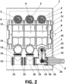
- the operating means (5) are mounted inside a second enclosure (11) and this second enclosure (11) in turn is mounted inside the first gas-insulated enclosure (1), therefore, the same insulating gas contained in the first enclosure (1) also allows the extinction of the electric arc generated between the contacts of the operating means (5) in the opening and closing operations.
- the bars (6) of the main circuit and the branch bars (7) comprise a cylindrical geometry, and also comprise at least one second joining means (14) that allows joining between bars (6) of the main circuit or joining between branch bars (7).
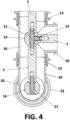
- the second joining means (14) comprises a rounded piece, such as of a ball or ball joint type, at least one fixing point (15) such as a bolt and it can also comprise at least one through hole (21) which can be passed through, for example, by a screw or a threaded stud, in such a way that it allows joining between different pieces of bars (6) or between different pieces of bars (7), thus obtaining, for example, T-bar joints, elbow joints, straight joints or cross joints.
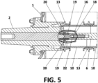
- the conductive parts (19) are tightened against the bars (6, 7) (of the main or branch circuit) by means of the tightening means (20), guaranteeing an appropriate electrical contact between said bars (6, 7) and the conductive parts (19).
- This connector (18) can also comprise a conductive terminal (22) arranged between the bar (6) of the main circuit or the branch bar (7) and said, at least one, conductive part (19) of the connector (18), so that, in this case, the bars (6, 7) are connected to said conductive terminal (22) and the latter is connected to the conductive parts (19).
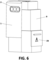
- the electrical switchgear comprises a cable compartment (23) wherein the electrical connection means (3) of the first gas-insulated enclosure (1) are accessible, on which some cables of the electrical network can be connected, and on said cable compartment (23) the operating mechanism (9) incorporated inside a third additional enclosure can be arranged.
Landscapes
- Engineering & Computer Science (AREA)
- Power Engineering (AREA)
- Gas-Insulated Switchgears (AREA)
- Organic Insulating Materials (AREA)
- Patch Boards (AREA)
- Switch Cases, Indication, And Locking (AREA)
Claims (13)
- Gasisolierte elektrische Schaltanlage für Mittel- und Hochspannungsstromnetze, umfassend:• ein erstes Gehäuse (1), das mit Gas isoliert ist und mit mindestens einem elektrischen Anschlussmittel (2, 3) und mindestens einem mechanischen Anschlussmittel (4) versehen ist;• ein Betätigungsmittel (5), das in einem zweiten Gehäuse (11) integriert ist, das zwischen mindestens einer Schiene (6) eines Hauptstromkreises und mindestens einer Abzweigschiene (7) angeordnet ist, wobei das Betätigungsmittel (5) einen Gastrennschalter umfasst, wobei das zweite Gehäuse (11), das mit dem Betätigungsmittel (5) ausgestattet ist, sich innerhalb des ersten Gehäuses (1) befindet;• ein Aktuierungselement (8), das so konfiguriert ist, dass es die Betätigungsmittel (5) betätigt, die die Funktionen des Trennens, Herstellens, Unterbrechen und Erdens ausführt; und• einen Betätigungsmechanismus (9), um die Betätigung des Aktuierungselements (8) zu bewirken;• wobei das mechanische Anschlussmittel (4) den Betätigungsmechanismus (9) mit dem ersten Gehäuse (1) koppelt;wobei die gasisolierte elektrische Schaltanlage dadurch gekennzeichnet ist, dass:• die Schaltanlage ferner eine Vielzahl von Abdeckungen (10) umfasst, die im Inneren konzentrisch die Schienen (6) des Hauptstromkreises und die Abzweigschienen (7) enthalten, wobei das Medium zwischen den Schienen (6, 7) und der Abdeckung (10) ein Gas ist;• das erste Gehäuse (1) umfasst innerhalb der Abdeckungen (10) die Schienen (6) des Hauptstromkreises und die Abzweigschienen (7);• die Abdeckungen (10) aus einem elektrisch nicht leitenden Material bestehen und Hohlteile mit zylindrischer Geometrie umfassen, die durch mindestens ein erstes Verbindungsmittel (13) miteinander verbunden sind; und dass• die Schienen (6) des Hauptstromkreises und die Abzweigschienen (7) eine zylindrische Geometrie aufweisen und dass sie ferner mindestens ein zweites Verbindungsmittel (14) umfassen, das eine Verbindung zwischen den Schienen (6) des Hauptstromkreises oder eine Verbindung zwischen den Abzweigschienen (7) ermöglicht.
- Elektrische Schaltanlage gemäß Anspruch 1, dadurch gekennzeichnet, dass die ersten Verbindungsmittel (13) ein elastisches Material umfassen, das eine Verbindung und Abdichtung zwischen den verschiedenen Teilen der Abdeckung (10) ermöglicht.
- Elektrische Schaltanlage gemäß Anspruch 1, dadurch gekennzeichnet, dass die Abdeckungen (10) mindestens ein Schließmittel (12) umfassen, das dazu bestimmt ist, mittels des ersten Verbindungsmittel (13) mit den Abdeckungen (10) an ihren offenen Enden verbunden zu werden.
- Elektrische Schaltanlage gemäß Anspruch 3, dadurch gekennzeichnet, dass das Schließmittel (12) aus einem elektrisch nicht-leitenden Material hergestellt ist.
- Elektrische Schaltanlage nach Anspruch 1, dadurch gekennzeichnet, dass das zweite Verbindungsmittel (14) ein abgerundetes Teil, mindestens einen Befestigungspunkt (15) und mindestens ein Durchgangsloch (21) umfasst.
- Elektrische Schaltanlage gemäß einem der vorstehenden Ansprüche, dadurch gekennzeichnet, dass das erste Gehäuse (1) abgedichtet, abgeschirmt und geerdet sowie in einem dielektrischen Gas bei einem relativen Druck isoliert ist.
- Elektrische Schaltanlage nach Anspruch 1, dadurch gekennzeichnet, dass das Betätigungsmittel (5) einen drehbaren Lasttrennschalter umfasst.
- Elektrische Schaltanlage gemäß Anspruch 6, dadurch gekennzeichnet, dass die elektrischen Anschlussmittel (2, 3) und die mechanischen Anschlussmittel (4) von außerhalb des Gehäuses (1) zugänglich sind.
- Elektrische Schaltanlage gemäß Anspruch 8, dadurch gekennzeichnet, dass die elektrischen Anschlussmittel (2, 3) jeweils über elektrische Verbindungen mit den Schienen (6) des Hauptstromkreises bzw. den Abzweigschienen (7) elektrisch verbunden sind, wobei die elektrischen Verbindungen von einem Diffusor (16) umgeben sind.
- Elektrische Schaltanlage gemäß Anspruch 9, dadurch gekennzeichnet, dass die elektrische Verbindung zwischen den elektrischen Anschlussmitteln (2, 3) und den Schienen (6, 7) einen Verbinder (18) umfasst, der so konfiguriert ist, dass er an einem seiner Enden mit den elektrischen Anschlussmitteln (2) und an einem anderen seiner Enden mit der Schiene (6) des Hauptstromkreises verbunden ist, oder so konfiguriert ist, dass er an einem Ende mit den elektrischen Anschlussmitteln (3) und am anderen Ende mit der Abzweigschiene (7) verbunden ist.
- Elektrische Schaltanlage gemäß Anspruch 10, dadurch gekennzeichnet, dass der Verbinder (18) mindestens ein leitendes Teil (19) und mindestens ein Spannmittel (20) umfasst, so dass die elektrische Verbindung zwischen dem mindestens einen leitenden Teil (19) und der Schiene (6) des Hauptstromkreises oder der Abzweigschiene (7) vom Steckertyp ist.
- Elektrische Schaltanlage gemäß Anspruch 11, dadurch gekennzeichnet, dass der Verbinder (18) einen leitenden Anschluss (22) umfasst, der zwischen der Schiene (6) des Hauptstromkreises oder der Abzweigschiene (7) und dem mindestens einen leitenden Teil (19) angeordnet ist.
- Elektrische Schaltanlage gemäß Anspruch 9, dadurch gekennzeichnet, dass die elektrischen Anschlussmittel (2, 3) mit den Abdeckungen (10) mittels der ersten Verbindungsmittel (13) gekoppelt sind.
Applications Claiming Priority (2)
| Application Number | Priority Date | Filing Date | Title |
|---|---|---|---|
| ES202130573U ES1276579Y (es) | 2021-03-23 | 2021-03-23 | Aparamenta eléctrica aislada en gas para redes de distribución eléctrica de media y alta tensión |
| PCT/ES2022/070164 WO2022200659A1 (en) | 2021-03-23 | 2022-03-22 | Gas-insulated electrical switchgear for medium and high voltage electrical distribution networks |
Publications (3)
| Publication Number | Publication Date |
|---|---|
| EP4315535A1 EP4315535A1 (de) | 2024-02-07 |
| EP4315535B1 true EP4315535B1 (de) | 2025-04-16 |
| EP4315535C0 EP4315535C0 (de) | 2025-04-16 |
Family
ID=77245014
Family Applications (1)
| Application Number | Title | Priority Date | Filing Date |
|---|---|---|---|
| EP22724799.6A Active EP4315535B1 (de) | 2021-03-23 | 2022-03-22 | Gasisolierte schaltanlage für mittel-und hochspannungsverteilungsnetzte |
Country Status (11)
| Country | Link |
|---|---|
| US (1) | US20240162694A1 (de) |
| EP (1) | EP4315535B1 (de) |
| CN (1) | CN117356002A (de) |
| AR (1) | AR125563A1 (de) |
| BR (1) | BR112023019415A2 (de) |
| CO (1) | CO2023012671A2 (de) |
| ES (2) | ES1276579Y (de) |
| HU (1) | HUE072111T2 (de) |
| MX (1) | MX2023011261A (de) |
| PL (1) | PL4315535T3 (de) |
| WO (1) | WO2022200659A1 (de) |
Families Citing this family (3)
| Publication number | Priority date | Publication date | Assignee | Title |
|---|---|---|---|---|
| EP4135136A1 (de) * | 2021-08-10 | 2023-02-15 | Hitachi Energy Switzerland AG | Gasisolierte hochspannungsschaltanlage (hv gis) für ein- oder dreiphasigen betrieb |
| CN116073256B (zh) * | 2023-01-10 | 2025-10-03 | 国网江苏省电力有限公司淮安供电分公司 | 智能应急电源快速接入箱 |
| CN120527789B (zh) * | 2025-07-25 | 2025-11-07 | 四川宝光电器设备有限公司 | 一种环保型气体绝缘环网柜 |
Family Cites Families (26)
| Publication number | Priority date | Publication date | Assignee | Title |
|---|---|---|---|---|
| CH653419A5 (de) * | 1978-12-06 | 1985-12-31 | Raychem Ltd | Verbindungsvorrichtung zum verbinden laenglicher teile und zugehoeriges verwendungsverfahren. |
| JPS56112826U (de) * | 1980-01-31 | 1981-08-31 | ||
| NL8900709A (nl) | 1989-03-22 | 1990-10-16 | Holec Syst & Componenten | Een of meerfasige middenspannings-schakelinrichting en een hiermee samengestelde middenspannings-verdeelinrichting. |
| SE9500294D0 (sv) | 1995-01-26 | 1995-01-26 | Asea Brown Boveri | Förfarande för att anordna ett strömskenesystem och ett strömskenesystem |
| DE19511168A1 (de) * | 1995-03-28 | 1996-10-02 | Abb Management Ag | Schaltvorrichtung |
| DE19615912A1 (de) * | 1996-04-22 | 1997-10-23 | Asea Brown Boveri | Trennschalter |
| JP2000357442A (ja) * | 1999-06-15 | 2000-12-26 | Toshiba Corp | 真空遮断器及び金属閉鎖形スイッチギヤ |
| US6373015B1 (en) | 2000-01-03 | 2002-04-16 | Eaton Corporation | Integral load connector module |
| NL1017797C2 (nl) | 2001-04-09 | 2002-10-10 | Holec Holland Nv | Een- of meerfasenschakelinrichting in een omhullende behuizing. |
| JP2004056844A (ja) | 2002-07-16 | 2004-02-19 | Meidensha Corp | ガス絶縁開閉装置 |
| AU2002335467A1 (en) * | 2002-09-30 | 2004-04-23 | Mitsubishi Denki Kabushiki Kaisha | Vacuum beaker |
| CN2796202Y (zh) * | 2005-06-06 | 2006-07-12 | 正泰电气股份有限公司 | 一种气体绝缘金属封闭开关设备 |
| KR101250261B1 (ko) * | 2011-12-20 | 2013-04-04 | 엘에스산전 주식회사 | 링 메인 유닛의 소호 장치 |
| DK3229323T3 (da) * | 2014-12-01 | 2020-05-04 | Ormazabal Y Cia S L U | Elektrisk forbindelseskabelforskruningsadapter |
| CN106329320B (zh) | 2015-07-03 | 2018-06-26 | 伊顿电力设备有限公司 | 主开关模块及固体绝缘环网柜 |
| CN105846335B (zh) | 2016-05-10 | 2018-02-02 | 广东紫光电气有限公司 | 一种12kV载流1250A固体绝缘开关柜 |
| CN205753147U (zh) | 2016-05-10 | 2016-11-30 | 广东紫光电气有限公司 | 一种12kV载流1250A固体绝缘开关柜 |
| CN205901163U (zh) | 2016-08-08 | 2017-01-18 | 桥控电气有限公司 | 一种固体环网柜 |
| CN205911661U (zh) | 2016-08-26 | 2017-01-25 | 深圳市惠程电气股份有限公司 | 固体绝缘环网柜的环氧臂异形母线 |
| CN206461287U (zh) * | 2017-03-03 | 2017-09-01 | 上海鲁研电力设备监理有限公司 | 一种减少gis组合电器sf6气体排放的装置 |
| WO2018232236A1 (en) | 2017-06-16 | 2018-12-20 | Eaton Intelligent Power Limited | Isolating gas-insulated bus arrangements for switchgear |
| CN111602220B (zh) * | 2018-01-15 | 2023-08-15 | 赛雪龙公司 | 电气开关装置 |
| CN207896544U (zh) | 2018-03-16 | 2018-09-21 | 厦门业盛电气有限公司 | 一种用于固体绝缘环网柜中的连接套管 |
| CN209217565U (zh) | 2018-11-19 | 2019-08-06 | 珠海许继电气有限公司 | 一种绝缘开关设备 |
| ES1229781Y (es) * | 2019-04-26 | 2019-08-12 | Ormazabal Y Cia S L U | Interruptor de corte en gas |
| EP4276870B1 (de) * | 2022-05-12 | 2026-04-22 | ABB Schweiz AG | Mittelspannungsschaltvorrichtung |
-
2021
- 2021-03-23 ES ES202130573U patent/ES1276579Y/es active Active
-
2022
- 2022-03-21 AR ARP220100657A patent/AR125563A1/es active IP Right Grant
- 2022-03-22 US US18/552,416 patent/US20240162694A1/en active Pending
- 2022-03-22 BR BR112023019415A patent/BR112023019415A2/pt unknown
- 2022-03-22 PL PL22724799.6T patent/PL4315535T3/pl unknown
- 2022-03-22 CN CN202280037088.7A patent/CN117356002A/zh active Pending
- 2022-03-22 MX MX2023011261A patent/MX2023011261A/es unknown
- 2022-03-22 HU HUE22724799A patent/HUE072111T2/hu unknown
- 2022-03-22 EP EP22724799.6A patent/EP4315535B1/de active Active
- 2022-03-22 WO PCT/ES2022/070164 patent/WO2022200659A1/en not_active Ceased
- 2022-03-22 ES ES22724799T patent/ES3026579T3/es active Active
-
2023
- 2023-09-25 CO CONC2023/0012671A patent/CO2023012671A2/es unknown
Also Published As
| Publication number | Publication date |
|---|---|
| ES1276579U (es) | 2021-08-16 |
| EP4315535A1 (de) | 2024-02-07 |
| BR112023019415A2 (pt) | 2023-11-28 |
| CN117356002A (zh) | 2024-01-05 |
| AR125563A1 (es) | 2023-07-26 |
| ES1276579Y (es) | 2021-11-15 |
| ES3026579T3 (en) | 2025-06-11 |
| HUE072111T2 (hu) | 2025-10-28 |
| WO2022200659A1 (en) | 2022-09-29 |
| PL4315535T3 (pl) | 2025-07-28 |
| EP4315535C0 (de) | 2025-04-16 |
| MX2023011261A (es) | 2023-10-03 |
| CO2023012671A2 (es) | 2023-12-20 |
| US20240162694A1 (en) | 2024-05-16 |
Similar Documents
| Publication | Publication Date | Title |
|---|---|---|
| EP4315535B1 (de) | Gasisolierte schaltanlage für mittel-und hochspannungsverteilungsnetzte | |
| US6259051B1 (en) | Vacuum switch and a vacuum switchgear using the same | |
| US5721412A (en) | Disconnector for a metal encapsulated, gas insulated high voltage switchgear | |
| CN101996815B (zh) | 开关装置以及开关装置的操作方法 | |
| CN101350506B (zh) | 真空绝缘开关装置 | |
| CN1825725B (zh) | 真空开关装置 | |
| KR101026842B1 (ko) | 고체절연 개폐장치용 단로기 | |
| JP4512648B2 (ja) | スイッチギヤ | |
| CN1377515A (zh) | 一种气体绝缘开关装置 | |
| CN102986100B (zh) | 具有包括空气和屏栅的单相隔离的开关设备 | |
| US20080217153A1 (en) | Insulating Body For a Medium-Voltage Switchgear Assembly | |
| US20130201607A1 (en) | Pressurised gas-insulated multi-phase control panel | |
| KR100846223B1 (ko) | 중전압 스위치기어 | |
| EP4057314B1 (de) | Schaltersicherungsmodul | |
| CN106571264B (zh) | 一种固体绝缘断路器 | |
| JP4572145B2 (ja) | ガス絶縁スイッチギヤ | |
| US7692113B2 (en) | Switch assembly | |
| RU2844885C2 (ru) | Газоизолированное электрическое распределительное устройство для средневольтных и высоковольтных электрических распределительных сетей | |
| EP4277059A1 (de) | Schaltanlagen für elektrische stromverteilungsnetze | |
| EP4542799A1 (de) | Elektrische verbindungsvorrichtung | |
| KR200463210Y1 (ko) | 가스절연개폐기의 접지장치 | |
| RU2420847C2 (ru) | Силовой выключатель с корпусом | |
| JP7221473B1 (ja) | ガス絶縁開閉装置 | |
| JP3237225B2 (ja) | タンク形ガス遮断器 | |
| CN101073132A (zh) | 具有至少三个同类断续器单元的多相开关装置 |
Legal Events
| Date | Code | Title | Description |
|---|---|---|---|
| STAA | Information on the status of an ep patent application or granted ep patent |
Free format text: STATUS: UNKNOWN |
|
| STAA | Information on the status of an ep patent application or granted ep patent |
Free format text: STATUS: THE INTERNATIONAL PUBLICATION HAS BEEN MADE |
|
| PUAI | Public reference made under article 153(3) epc to a published international application that has entered the european phase |
Free format text: ORIGINAL CODE: 0009012 |
|
| STAA | Information on the status of an ep patent application or granted ep patent |
Free format text: STATUS: REQUEST FOR EXAMINATION WAS MADE |
|
| 17P | Request for examination filed |
Effective date: 20231018 |
|
| AK | Designated contracting states |
Kind code of ref document: A1 Designated state(s): AL AT BE BG CH CY CZ DE DK EE ES FI FR GB GR HR HU IE IS IT LI LT LU LV MC MK MT NL NO PL PT RO RS SE SI SK SM TR |
|
| DAV | Request for validation of the european patent (deleted) | ||
| DAX | Request for extension of the european patent (deleted) | ||
| GRAP | Despatch of communication of intention to grant a patent |
Free format text: ORIGINAL CODE: EPIDOSNIGR1 |
|
| STAA | Information on the status of an ep patent application or granted ep patent |
Free format text: STATUS: GRANT OF PATENT IS INTENDED |
|
| RIC1 | Information provided on ipc code assigned before grant |
Ipc: H01H 33/02 20060101ALN20241003BHEP Ipc: H01H 31/00 20060101ALN20241003BHEP Ipc: H01H 33/56 20060101ALI20241003BHEP Ipc: H01H 33/24 20060101ALI20241003BHEP Ipc: H01H 33/12 20060101ALI20241003BHEP Ipc: H02B 13/035 20060101AFI20241003BHEP |
|
| RAP3 | Party data changed (applicant data changed or rights of an application transferred) |
Owner name: ORMAZABAL Y CIA., S.L.U. |
|
| RIN1 | Information on inventor provided before grant (corrected) |
Inventor name: SANCHEZ RUIZ, JUAN ANTONIO Inventor name: RANEDO TORRES, LUIS |
|
| INTG | Intention to grant announced |
Effective date: 20241016 |
|
| RAP3 | Party data changed (applicant data changed or rights of an application transferred) |
Owner name: ORMAZABAL Y CIA., S.L.U. |
|
| GRAS | Grant fee paid |
Free format text: ORIGINAL CODE: EPIDOSNIGR3 |
|
| GRAA | (expected) grant |
Free format text: ORIGINAL CODE: 0009210 |
|
| STAA | Information on the status of an ep patent application or granted ep patent |
Free format text: STATUS: THE PATENT HAS BEEN GRANTED |
|
| AK | Designated contracting states |
Kind code of ref document: B1 Designated state(s): AL AT BE BG CH CY CZ DE DK EE ES FI FR GB GR HR HU IE IS IT LI LT LU LV MC MK MT NL NO PL PT RO RS SE SI SK SM TR |
|
| REG | Reference to a national code |
Ref country code: GB Ref legal event code: FG4D |
|
| REG | Reference to a national code |
Ref country code: CH Ref legal event code: EP |
|
| REG | Reference to a national code |
Ref country code: IE Ref legal event code: FG4D |
|
| REG | Reference to a national code |
Ref country code: DE Ref legal event code: R096 Ref document number: 602022013266 Country of ref document: DE |
|
| U01 | Request for unitary effect filed |
Effective date: 20250429 |
|
| U07 | Unitary effect registered |
Designated state(s): AT BE BG DE DK EE FI FR IT LT LU LV MT NL PT RO SE SI Effective date: 20250507 |
|
| REG | Reference to a national code |
Ref country code: ES Ref legal event code: FG2A Ref document number: 3026579 Country of ref document: ES Kind code of ref document: T3 Effective date: 20250611 |
|
| PG25 | Lapsed in a contracting state [announced via postgrant information from national office to epo] |
Ref country code: NO Free format text: LAPSE BECAUSE OF FAILURE TO SUBMIT A TRANSLATION OF THE DESCRIPTION OR TO PAY THE FEE WITHIN THE PRESCRIBED TIME-LIMIT Effective date: 20250716 |
|
| PG25 | Lapsed in a contracting state [announced via postgrant information from national office to epo] |
Ref country code: HR Free format text: LAPSE BECAUSE OF FAILURE TO SUBMIT A TRANSLATION OF THE DESCRIPTION OR TO PAY THE FEE WITHIN THE PRESCRIBED TIME-LIMIT Effective date: 20250416 |
|
| PG25 | Lapsed in a contracting state [announced via postgrant information from national office to epo] |
Ref country code: RS Free format text: LAPSE BECAUSE OF FAILURE TO SUBMIT A TRANSLATION OF THE DESCRIPTION OR TO PAY THE FEE WITHIN THE PRESCRIBED TIME-LIMIT Effective date: 20250716 |
|
| PG25 | Lapsed in a contracting state [announced via postgrant information from national office to epo] |
Ref country code: IS Free format text: LAPSE BECAUSE OF FAILURE TO SUBMIT A TRANSLATION OF THE DESCRIPTION OR TO PAY THE FEE WITHIN THE PRESCRIBED TIME-LIMIT Effective date: 20250816 |
|
| REG | Reference to a national code |
Ref country code: HU Ref legal event code: AG4A Ref document number: E072111 Country of ref document: HU |
|
| PG25 | Lapsed in a contracting state [announced via postgrant information from national office to epo] |
Ref country code: SM Free format text: LAPSE BECAUSE OF FAILURE TO SUBMIT A TRANSLATION OF THE DESCRIPTION OR TO PAY THE FEE WITHIN THE PRESCRIBED TIME-LIMIT Effective date: 20250416 |
|
| PG25 | Lapsed in a contracting state [announced via postgrant information from national office to epo] |
Ref country code: SK Free format text: LAPSE BECAUSE OF FAILURE TO SUBMIT A TRANSLATION OF THE DESCRIPTION OR TO PAY THE FEE WITHIN THE PRESCRIBED TIME-LIMIT Effective date: 20250416 |
|
| PLBE | No opposition filed within time limit |
Free format text: ORIGINAL CODE: 0009261 |
|
| STAA | Information on the status of an ep patent application or granted ep patent |
Free format text: STATUS: NO OPPOSITION FILED WITHIN TIME LIMIT |
|
| REG | Reference to a national code |
Ref country code: CH Ref legal event code: L10 Free format text: ST27 STATUS EVENT CODE: U-0-0-L10-L00 (AS PROVIDED BY THE NATIONAL OFFICE) Effective date: 20260225 |
|
| 26N | No opposition filed |
Effective date: 20260119 |
|
| REG | Reference to a national code |
Ref country code: CH Ref legal event code: U11 Free format text: ST27 STATUS EVENT CODE: U-0-0-U10-U11 (AS PROVIDED BY THE NATIONAL OFFICE) Effective date: 20260401 |
|
| U20 | Renewal fee for the european patent with unitary effect paid |
Year of fee payment: 5 Effective date: 20260225 |
|
| PGFP | Annual fee paid to national office [announced via postgrant information from national office to epo] |
Ref country code: GB Payment date: 20260225 Year of fee payment: 5 |
|
| PGFP | Annual fee paid to national office [announced via postgrant information from national office to epo] |
Ref country code: IE Payment date: 20260227 Year of fee payment: 5 |
|
| PGFP | Annual fee paid to national office [announced via postgrant information from national office to epo] |
Ref country code: HU Payment date: 20260325 Year of fee payment: 5 |