EP4315306B1 - Modular construction system light matrix - Google Patents
Modular construction system light matrix Download PDFInfo
- Publication number
- EP4315306B1 EP4315306B1 EP22718598.0A EP22718598A EP4315306B1 EP 4315306 B1 EP4315306 B1 EP 4315306B1 EP 22718598 A EP22718598 A EP 22718598A EP 4315306 B1 EP4315306 B1 EP 4315306B1
- Authority
- EP
- European Patent Office
- Prior art keywords
- diffuser
- grid
- compartment
- housing
- modular construction
- Prior art date
- Legal status (The legal status is an assumption and is not a legal conclusion. Google has not performed a legal analysis and makes no representation as to the accuracy of the status listed.)
- Active
Links
Images






Classifications
-
- H—ELECTRICITY
- H05—ELECTRIC TECHNIQUES NOT OTHERWISE PROVIDED FOR
- H05B—ELECTRIC HEATING; ELECTRIC LIGHT SOURCES NOT OTHERWISE PROVIDED FOR; CIRCUIT ARRANGEMENTS FOR ELECTRIC LIGHT SOURCES, IN GENERAL
- H05B33/00—Electroluminescent light sources
- H05B33/12—Light sources with substantially two-dimensional [2D] radiating surfaces
-
- F—MECHANICAL ENGINEERING; LIGHTING; HEATING; WEAPONS; BLASTING
- F21—LIGHTING
- F21V—FUNCTIONAL FEATURES OR DETAILS OF LIGHTING DEVICES OR SYSTEMS THEREOF; STRUCTURAL COMBINATIONS OF LIGHTING DEVICES WITH OTHER ARTICLES, NOT OTHERWISE PROVIDED FOR
- F21V11/00—Screens not covered by groups F21V1/00, F21V3/00, F21V7/00 or F21V9/00
- F21V11/06—Screens not covered by groups F21V1/00, F21V3/00, F21V7/00 or F21V9/00 using crossed laminae or strips, e.g. grid-shaped louvers; using lattices or honeycombs
-
- F—MECHANICAL ENGINEERING; LIGHTING; HEATING; WEAPONS; BLASTING
- F21—LIGHTING
- F21V—FUNCTIONAL FEATURES OR DETAILS OF LIGHTING DEVICES OR SYSTEMS THEREOF; STRUCTURAL COMBINATIONS OF LIGHTING DEVICES WITH OTHER ARTICLES, NOT OTHERWISE PROVIDED FOR
- F21V23/00—Arrangement of electric circuit elements in or on lighting devices
- F21V23/003—Arrangement of electric circuit elements in or on lighting devices the elements being electronics drivers or controllers for operating the light source, e.g. for a LED array
- F21V23/004—Arrangement of electric circuit elements in or on lighting devices the elements being electronics drivers or controllers for operating the light source, e.g. for a LED array arranged on a substrate, e.g. a printed circuit board
- F21V23/005—Arrangement of electric circuit elements in or on lighting devices the elements being electronics drivers or controllers for operating the light source, e.g. for a LED array arranged on a substrate, e.g. a printed circuit board the substrate is supporting also the light source
-
- F—MECHANICAL ENGINEERING; LIGHTING; HEATING; WEAPONS; BLASTING
- F21—LIGHTING
- F21V—FUNCTIONAL FEATURES OR DETAILS OF LIGHTING DEVICES OR SYSTEMS THEREOF; STRUCTURAL COMBINATIONS OF LIGHTING DEVICES WITH OTHER ARTICLES, NOT OTHERWISE PROVIDED FOR
- F21V3/00—Globes; Bowls; Cover glasses
- F21V3/04—Globes; Bowls; Cover glasses characterised by materials, surface treatments or coatings
- F21V3/049—Patterns or structured surfaces for diffusing light, e.g. frosted surfaces
-
- F—MECHANICAL ENGINEERING; LIGHTING; HEATING; WEAPONS; BLASTING
- F21—LIGHTING
- F21V—FUNCTIONAL FEATURES OR DETAILS OF LIGHTING DEVICES OR SYSTEMS THEREOF; STRUCTURAL COMBINATIONS OF LIGHTING DEVICES WITH OTHER ARTICLES, NOT OTHERWISE PROVIDED FOR
- F21V33/00—Structural combinations of lighting devices with other articles, not otherwise provided for
-
- F—MECHANICAL ENGINEERING; LIGHTING; HEATING; WEAPONS; BLASTING
- F21—LIGHTING
- F21V—FUNCTIONAL FEATURES OR DETAILS OF LIGHTING DEVICES OR SYSTEMS THEREOF; STRUCTURAL COMBINATIONS OF LIGHTING DEVICES WITH OTHER ARTICLES, NOT OTHERWISE PROVIDED FOR
- F21V5/00—Refractors for light sources
-
- F—MECHANICAL ENGINEERING; LIGHTING; HEATING; WEAPONS; BLASTING
- F21—LIGHTING
- F21V—FUNCTIONAL FEATURES OR DETAILS OF LIGHTING DEVICES OR SYSTEMS THEREOF; STRUCTURAL COMBINATIONS OF LIGHTING DEVICES WITH OTHER ARTICLES, NOT OTHERWISE PROVIDED FOR
- F21V7/00—Reflectors for light sources
- F21V7/04—Optical design
- F21V7/05—Optical design plane
-
- G—PHYSICS
- G09—EDUCATION; CRYPTOGRAPHY; DISPLAY; ADVERTISING; SEALS
- G09F—DISPLAYING; ADVERTISING; SIGNS; LABELS OR NAME-PLATES; SEALS
- G09F9/00—Indicating arrangements for variable information in which the information is built-up on a support by selection or combination of individual elements
- G09F9/30—Indicating arrangements for variable information in which the information is built-up on a support by selection or combination of individual elements in which the desired character or characters are formed by combining individual elements
- G09F9/302—Indicating arrangements for variable information in which the information is built-up on a support by selection or combination of individual elements in which the desired character or characters are formed by combining individual elements characterised by the form or geometrical disposition of the individual elements
-
- G—PHYSICS
- G09—EDUCATION; CRYPTOGRAPHY; DISPLAY; ADVERTISING; SEALS
- G09F—DISPLAYING; ADVERTISING; SIGNS; LABELS OR NAME-PLATES; SEALS
- G09F9/00—Indicating arrangements for variable information in which the information is built-up on a support by selection or combination of individual elements
- G09F9/30—Indicating arrangements for variable information in which the information is built-up on a support by selection or combination of individual elements in which the desired character or characters are formed by combining individual elements
- G09F9/33—Indicating arrangements for variable information in which the information is built-up on a support by selection or combination of individual elements in which the desired character or characters are formed by combining individual elements being semiconductor devices, e.g. diodes
-
- F—MECHANICAL ENGINEERING; LIGHTING; HEATING; WEAPONS; BLASTING
- F21—LIGHTING
- F21Y—INDEXING SCHEME ASSOCIATED WITH SUBCLASSES F21K, F21L, F21S and F21V, RELATING TO THE FORM OR THE KIND OF THE LIGHT SOURCES OR OF THE COLOUR OF THE LIGHT EMITTED
- F21Y2105/00—Planar light sources
- F21Y2105/10—Planar light sources comprising a two-dimensional [2D] array of point-like light-generating elements
- F21Y2105/14—Planar light sources comprising a two-dimensional [2D] array of point-like light-generating elements characterised by the overall shape of the two-dimensional [2D] array
- F21Y2105/16—Planar light sources comprising a two-dimensional [2D] array of point-like light-generating elements characterised by the overall shape of the two-dimensional [2D] array square or rectangular, e.g. for light panels
Definitions
- the present invention relates to a modular construction system and a modular construction system light matrix.
- Modular construction systems as such are known in the art, as is various modular construction system units, for example motor units, for such modular construction systems etc.
- Modular construction systems comprises a plurality of construction elements, for example building blocks or bricks, which - when connected together-may be assembled to form a variety of different building structures. Motor units may be added to such modular construction systems in order to make parts of such system move.
- a modular construction system light matrix allows to provide a building structure formed from such construction elements, for example building blocks or bricks, frames, connectors, beams etc. with light output.
- the modular construction system light matrixes according to the invention may be used to form eyes of a robot constructed from construction elements.
- Modular construction systems are "modular" in the sense that the construction elements making up the construction systems are sized and shaped and comprise cooperating connection means allowing their interconnection, such that models/sets, such as figures robots, etc. may be constructed.
- Modular construction elements as they are known from traditional modular construction systems, such as beams, plates, bricks, pegs, connectors, cog-wheels, etc., may be combined with functional modular construction elements, such as lighting elements, motors/actuators, sensors, but also programmable processor units, which may also be digitally connectable with external devices, e.g. for programming or remote control.
- Such modular construction systems with enhanced functionality have proven their value in a play and/or learning context, not the least because they facilitate reliable, yet easily detachable mechanical connections between simple and functional modular construction elements, and because the functional modular construction elements are adapted to each other to provide a positive and stimulating user experience.
- Light matrices as such are known in the art. On example is shown in a video at the internet location https://learn.adafruit.com/sqaure-neopixel-display-with-black-led-acrylic; see especially from 2:15 to 2:38. Screen dumps from this video is shown in Figs. 1A and 1B in the attached drawings. Although, this the video discusses the problem of light bleeding, the problem of light is not successfully solved in the light matrix shown.
- the phenomenon "light bleeding” occurs, in situations where two or more light sources are arranged in the vicinity of each other, and light from one lights source "bleeds" through openings in a light source housing or through the housing itself and distorts or changes the visual appearance of the light from the other light source.
- the present invention alleviates some of these problems of the prior art.
- a modular construction system light matrix comprising
- the diffuser tiles are made by a material capable of allowing light to pass there through while diffusing the light.
- the diffuser grid comprises first diffuser grid walls and intersecting second diffuser grid walls, and the first diffuser grid walls and intersecting second diffuser grid walls are aligned with the compartment grid walls of the compartment grid.
- the compartment grid may be made by a light absorbing material.
- the diffuser grid is made from a light absorbing material.
- the diffuser grid is made by a light reflecting material.
- the diffuser grid may be formed in the same material as the side walls of the housing.
- outwardly facing sidewalls of the diffuser tiles extend in front of said front edge and forms an extension of the sidewalls of the housing and flush therewith.
- each diffuser tile comprises a compartment portion extending into a compartment provided by the compartment grid.
- outwardly facing surfaces of the compartment portion of the diffuser tiles arranged at external edges and corners of the diffuser element are angled relative to the outwardly facing sidewalls of the diffuser tiles.
- light emitted from the light emitting elements is directed also towards the side walls of the diffuser tiles.
- the angle between the side walls of the diffuser tiles and the corresponding outwardly facing surface is acute.
- the compartment portion of the diffuser tiles formed at external corners of the diffuser element comprises a first surface formed between outwardly facing side surfaces at the external corners of the diffuser element, which first surface interconnects the two outwardly facing side surfaces of the compartment portion.
- the first surface forms an angel of 45° relative to the two adjacent outwardly facing side surfaces.
- the diffuser tiles are interconnected by tile connecting element formed integrally with and in the same material as the diffuser tiles.
- the diffuser grid may be formed in spaces between the diffuser tiles as the second stage in a two stage moulding process (two component moulding process), where the diffuser tiles with the connecter elements are formed in the first stage of the two stage moulding process (two component moulding process).
- the connecting elements are protrusions extending from the lower surface of the diffuser tiles, at corners of the diffuser tiles, where four neighbouring diffuser tiles meet.
- internal surfaces of the compartments of the compartment grid are covered by internal walls formed in a material different from the material of the compartment grid.
- the internal walls may be formed in a light reflecting material.
- the internal walls are made from the same material as the sidewalls of the housing.
- the internal walls are formed integral with the housing.
- at least the sidewalls of the housing may be formed together with the internal walls in a second injection moulding stage of a two stage moulding process (two component moulding process), where a compartment grid formed in the first injection moulding stage of a two stage moulding process (two component moulding process) is used as core in the second injection moulding stage.
- the internal walls taper outwards towards the diffuser element.
- internal walls of the compartment grid may taper outwards towards the diffuser element.
- outwardly facing sidewalls of the diffuser element may extend in front of said front edge and form an extension of the sidewalls of the housing and flush therewith.
- the housing comprises connector openings complementary with connector pegs of a modular construction system.
- a modular construction system light matrix comprising
- the modular construction system light matrix according to the second aspect may further comprise any of the further features of the embodiments, of the first aspect of the invention.
- Figs. 1A-B show an example of a prior art light matrix 900, in a disassembled state to unveil components thereof.
- Fig. 1A shows a square lower housing part 910 having a LED array 920 formed inside the lower housing part 910, and a grid 930 made in a dark plastic material and configured to form a compartment around each of the LEDs 925 of the LED array 920.
- the LEDs are arranged in a regular two-dimensional pattern on a surface of a plate 940 - presumably a printed circuit board, the plate 940 being mounted in the lower housing part 910.
- the grid 930 is disassembled from the lower housing part 910.
- the grid 930 is arranged in the lower housing part 910 and forming a compartment around each of the LEDs 925 of the LED array 920 and abutting on an upper surface of the plate 940.
- FIG. 1B Also shown in Fig. 1B is an upper housing part 950 in the form of an upper frame 960 and a diffuser plate 970 arranged in the upper frame 960.
- the diffuser plate 970 is a continuous unitary structure, made in a material suitable for diffusing light travelling through the diffuser plate 970.
- the diffuser plate 970 is sized and shaped to cover an opening provided in and through a top surface - defined by a circumferential flange of the upper frame 950 -by fitting into the upper frame 950 and abutting on lower surface of the circumferential flange of the upper frame 950.
- the upper housing part 950 is sized and shaped to cooperate with the lower housing part 910 to form a closed, boxed shaped light matrix unit (not shown).
- the LEDs 925 of the LED array 920 may be of a type capable of emitting light in several colors or the LEDs 925 may each emit a different color.
- the purpose of the grid 930 which is made in a dark plastic material is to form compartments 980 for each LED 925, such that light from one compartment does not "bleed” into a neighboring compartment, and such that the compartments 980 partitions the front surface of the diffuser plate into an array of square fields, which may show different colors in neighboring fields with light from one field "bleeding" into, and influencing the light in another square fields. As mentioned above, this is not always successfully achieved, as the diffuser plate material "draws" light from one compartment to another.
- Fig. 2A in a perspective view, shows a modular construction system light matrix 1 according to some embodiments of the invention.
- Fig. 2B also in a perspective view, shows the modular construction system light matrix from the rear or bottom side.
- Fig. 3 also in a perspective view, shows an embodiment of the modular construction system light matrix 1, in a disassembled state.
- the modular construction system light matrix 1 - hereinafter called a light matrix 1 - comprises a housing 100, an array 200 comprising a plurality of light emitting elements 210 arranged within the housing 100, a light diffusing element 400, and a compartment grid 300, arranged in the housing 100 between the array 200 of light emitting elements 210 and the light diffusing element 400.
- the housing 100 may - as shown - comprise an upper housing part 101 and a lower housing part 102, where the upper housing part 101 and the lower housing part 102 are interconnectable to form the complete housing 100.
- the plurality of light emitting elements 210 may be arranged on a 2D grid such as a grid defining, for example, a rectangle, a square, a circle, etc. If the grid is in a rectangular or square shape, the light matrix may be a square matrix, i.e. have the same number of light emitting elements 210 in its rows and columns, e.g. a 2x2, 3x3, 4x4, etc. However, in other embodiments, the number of rows and columns of light emitting elements 210 may differ.
- the separate light emitting elements 210 may be Light Emitting Diodes (LEDs), and they may be of the same type and/or model, or different.
- LEDs Light Emitting Diodes
- the colour and/or the intensity of each of the light emitting elements 210 may be controlled individually, such that some or all of the light emitting elements may be on or off at a given time.
- the light matrix 1 can receive digital information and preferably is provided with processing power to decode digital information to regulate the colour and intensity of each of the light emitting elements, for example as requested directly by a user or by a software program.
- the array 200 of light emitting elements 210 may as shown be regular 3 ⁇ 3 array (orthogonally arranged in 3 rows and 3 columns) of light emitting elements 210, i.e. with a total of 9 light emitting elements 210.
- the light emitting elements 210 are preferably - and as shown in e.g. Fig. 3 - mounted on a printed circuit board (PCB) 250.
- PCB printed circuit board
- PCB's are formed in a green material. This material however is quite transparent to light. In order to reduce this source of light bleeding through the housing 100, such as the back side of the housing or lower housing part 102, in preferred embodiments, a black - more light absorbing - PCB material is chosen.
- the control for regulating the light emitting elements 210 may be provided as components on the PCB 250.
- the light matrix 1 may further comprise electronic components, such as electronic control components, an energy source (e.g. a battery package), etc.
- electronic components such as electronic control components, an energy source (e.g. a battery package), etc.
- any such further electronic components are provided in the lower housing part 101 or on the PCB 250, preferably on the back side of the PCB.
- the light matrix 1 may further comprise means for communicating with external devices or a user.
- control input for the light emitting elements 210 may be provided from an external device being in wireless communication (not shown) with the light matrix 1.
- the light matrix 1 may comprises a cable unit 800 comprising one or more electrical cables 810 and a connector plug 820 configured for connecting the light matrix 1 with an external device. Thereby, information (control signals) and/or energy (electrical) may be transferred to the light matrix 1 from the (not shown) external device.
- the housing 100 preferably has a quadratic cross section, when the array 200 of light emitting elements 210 is an n ⁇ n array.
- the housing 100 may comprise two parts, an upper housing part 101 and a lower housing part 102. It will however be appreciated that the housing may - in not shown embodiments - be formed as a single part. In yet other embodiments the housing may comprise more than two parts.
- the housing 100 is preferably a box-shaped structure having a set of side walls 110 and preferably a bottom wall/end wall 110.
- the housing 100 comprises an upper housing part 101 and a lower housing part 102
- each of the sidewalls 110 has a wall portion being defined on the upper housing part 101 and a wall portion defined on the lower housing part 102.
- the bottom wall/end wall 110 is provided by the lower housing part 102
- the lower housing part 102 has the shape of an open box before mounting of other components.
- the upper housing part 101 in this case is a tubular structure, having sidewalls 110 and open upper and lower ends (before mounting of other components.
- the sidewalls of the upper housing part 101 and the sidewalls 110 of the lower housing part 102 are configured to cooperate, such that when the upper housing part 101 and the lower housing part 102 are assembled, they collectively form the housing 100.
- the side wall 110 of the housing 100 - and thereby the housing 100 - has an upper edge or front edge 130, which encircles an upper or front opening 140 of the housing 100.
- the front opening 140 is arranged opposite to said end wall 120 in the housing 100.
- the upper edge or front edge 130 and the upper or front opening 140 are provided on the upper housing part 101.
- the above mentioned light diffusing element 400 is arranged on and connectable to the housing 100, such that the light diffusing element 400 covers the front opening 140.
- a lower or downwardly facing edge 470 of the light diffusing element 400 is configured to rest on the front edge 130 of the housing 100.
- a light diffusing element for example as shown in the figures, and described below in connection with Figs. 6A-D may alternatively be configured to be located between internally facing sides of the sidewalls of the housing or an upper housing part thereof.
- the light diffusing element 400 covers the front opening 140 provided in the upper housing part 101, and the lower or downwardly facing edge 470 of the light diffusing element 400 is configured to rest on the front edge 130 of the upper housing part 101 of the housing 100.
- the diffuser element 400 and the housing 100 can be configured such that the sidewalls 440 of the diffuser element 400 are flush with the sidewall 110 of the housing 100, as shown in e.g. Fig. 2A .
- the light matrix 1 comprises a compartment grid 300.
- the compartment grid 300 may be formed in a light absorbing material.
- the compartment grid 300 may be made in a black polymer material.
- the compartment grid 300 is arranged within the housing 100.
- the compartment grid 300 comprises grid walls (may also be called compartment grid walls), two or more first compartment grid walls 310, and two or more a second set of first compartment grid walls 320.
- the first compartment grid walls 310 are arranged in parallel to each other.
- the second compartment grid walls 320 are arranged in parallel to each other.
- the first compartment grid walls 310 are arranged perpendicular to the second compartment grid walls 320.
- the first compartment grid walls 310 and the second compartment grid walls 320 intersect, and form compartments 330 between them.
- the compartment grid 300 is configured, such that one compartment 330 is provided for each light emitting element 210 of the array 200 of light emitting elements 210.
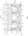
- the compartment grid 300 is further configured such that the compartment grid walls/grid walls 310, 320 allows the compartment grid 300 to extend from the surface (such as the upper/upwardly facing surface of a PCB 250) on which the light emitting elements 210 are arranged, and towards said front opening 140 of the housing 100, such as to a bottom/lower/downwardly facing surface of the light diffusing element 400, as shown in e.g. Fig. 4 and 5 .
- the compartment grid 300 may be an individual element which is mounted within the housing 100 during an assembly stage of manufacturing the light matrix 1.
- compartment grid 300 may be formed together with the housing 100, for example in a two stage injection moulding process (two component moulding process).
- the compartment grid 300 has two first compartment grid walls 310 and two intersecting second compartment grid walls 320 forming a grid or array of nine compartments 330, in a 3 ⁇ 3 array, where only the central compartment 330 is closed on all sides, and where the eight compartments 330 formed along the perimeter of the compartment grid 300 are open in the sense that these compartment have an externally facing side, facing an inner surface of the housing side walls 110 (when assembled), which is not covered by a wall.
- a "loose" compartment grid 300 as shown in Fig. 3 may have first compartment grid walls 310 and second compartment grid walls 320 formed along and facing the inner surface of the housing side walls 110 (when assembled), such that all of the compartment 330 are closed sideways.
- the compartment grid 300 comprises first compartment grid walls 310 and second compartment grid walls 320 formed along and facing the inner surface of the housing side walls 110, such that all of the compartment 330 are closed sideways.
- the compartment grid 300 has four first compartment grid walls 310 and four intersecting second compartment grid walls 320 forming a grid or array of nine compartments 330, in a 3 ⁇ 3 array, where all the compartments are closed on all sides.
- the housing 100 is provided with at least one modular connector 600 for connecting the light matrix 1 to another construction element of a modular construction system.
- the housing 100 is provided with six such modular connectors 600, two in the end wall 120, and two in each of two opposed side wall 110 of the housing 100.
- the modular connectors 600 are provided in the lower housing element 102.
- one or more connectors may be provided in the upper housing part 101 also.
- the modular connectors 600 are formed as indentions into and through the housing 100.
- the connectors are preferably connector openings.
- the one or more modular connectors 600 are configured for cooperating with and connecting to various types of construction elements of a modular construction.
- An example of a construction system having such connectors is known in the art, e.g. under the trade name LEGO TECHNIC ⁇ , marketed by LEGO A/S.
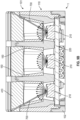
- Fig. 4 in a perspective sectional view, shows an upper portion of a modular construction system light matrix according to an embodiment of the invention. The section is taken along a side wall of the light matrix 1 housing 100.
- the compartment grid 300 is formed in a light absorbent material. In some embodiments the compartment grid 300 is formed in in a polymer material. Preferably, the compartment grid 300 is formed in a polymer material suitable for injection moulding. In some embodiments, the compartment grid 300 is formed in a black polymer material. Such a material may be black colored ABS plastic, which has high light absorption properties and low light reflection properties. This help containing the light and stopping it from traveling between the compartments 330, and through the outermost compartment grid walls 310, 320 and the outer walls, sidewalls 110, of the housing 100.
- the housing 100 or at least the upper housing portion 101 may be formed in a reflective polymer material, and preferably in a polymer material suitable for use in an injection moulding process.
- the housing 100 may further comprises internal walls 150, see e.g. Fig. 4 , also made in a light reflecting material.
- This material may be the same as used for the housing 100 as such.
- the black ABS plastic material (or materials with similar properties) of the compartment grid 300 prevents the light from zig zagging between white reflective and the black parts and between the (black) PCB 250 and the black compartment grid 300.
- the diffuser element 400 and the compartment grid 300 are assembled, to avoid air gaps there between.
- airgaps may not be possible to eliminate entirely, for example due to production tolerances.
- the black or other light absorbent properties of the compartment grid 300 may secure that, where at the few places where there are airgaps between the upper edge of the reflecting inner walls and the diffuser element, it is secured, that the compartment grid 300 is always on one side of these airgaps. This limits the amount the light that can "zig-zag" between the parts, and thereby the light bleeding between the compartments 330 and between compartments 330 and the sidewalls 110 of the housing 100.
- Fig. 5 in a side sectional view, shows the upper portion of a modular construction system light matrix according to the same embodiment of the invention as Fig.4 , but in a section different than in Fig. 4 .
- Figs. 6A-D preferred embodiments are illustrated in Figs. 6A-D .
- Portions of the diffuser element 400 is preferably formed in a material capable of allowing light to pass there through while diffusing the light, or a transparent material treated to give light diffusing properties.
- the diffuser element 400 comprises a plurality of diffuser tiles 410.
- a diffuser tile 410 is provided for each compartment 330 of the compartment grid 300, and covers the compartment 330 with which it is associated.
- the diffuser tiles are preferably formed in a material capable of allowing light to pass there-through while diffusing the light, or a transparent material treated to give light diffusing properties.
- the diffuser element is provided such that there is a diffuser tile 410 for each light emitting element 210.
- the above mentioned compartment grid 300 is manufactured such that there is one compartment for each light emitting element 210.
- Each of the diffuser tiles 410 comprises a front surface 420, a back surface 430 and sidewalls 440.
- the front surface 420 and the back surface 430 are formed parallel to each other.
- the sidewalls 440 of a diffuser tile 410 are formed perpendicularly to the front surface 420.
- the diffuser tiles 410 are arranged in a regular, two-dimensional array, some of the sidewalls 440 of the diffuser tiles 410 will face the sidewalls 440 of the neighbouring diffuser tiles 410, i.e. they have mutually facing sidewalls 442, while the diffuser tiles 410 formed along edges of the diffuser element 400 also have outwardly facing sidewalls 442, i.e. sidewalls not facing other diffuser tiles 410.
- the diffuser element 400 comprises a diffuser grid 500 providing a barrier between the mutually facing sidewalls 442 of the diffuser tiles 410.
- This diffuser grid 500 is preferably formed in a material different from a material of the diffuser tiles 410.
- the diffuser grid 500 comprises an array of diffuser grid walls, first diffuser grid walls 510 and intersecting second diffuser grid walls 520.
- the first diffuser grid walls 510 and intersecting second diffuser grid walls 520 are aligned with the compartment grid walls 310, 320 of the compartment grid 300, when the diffuser element 400 is assembled with the housing and the compartment grid.
- the compartment grid 300 and the diffuser element 400 are also assembled such that the diffuser grid walls 510, 520 abut on the compartment grid walls 310, 320, to minimize air gaps there between as also mentioned above. Thereby, light bleeding between the compartments 330 and the square light fields or zones provided by the diffuser tiles 410 is minimized or even prevented.
- a lower side (or at least a portion thereof) of the diffuser grid 500 is adapted to abut against an upper side (or at least a portion thereof) of the compartment grid 300.
- the compartment grid 300 and the diffuser grid 500 are separate entities, that when the light matrix 1 is assembled abuts against each other.
- the diffuser grid 500 and the diffuser tiles are formed together as a single unit, for example in a two stage moulding process.
- the diffuser grid 500 is formed in a light absorbing material. However, in alternative embodiments the diffuser grid 500 is formed in a light reflecting material.
- the diffuser grid 500 may be formed in the same material as the housing 100, or at least the same material as the side walls 110 of the housing 100.
- the outwardly facing sidewalls 441 of the diffuser element 400 and in embodiments, where the diffuser element 400 comprises diffuser tiles 410 extend in front of or above the front edge 130, such that the outwardly facing sidewalls 441 of the diffuser element 400/diffuser tiles 410 form an extension of the sidewalls 110 of the housing 100 in the plane of the sidewalls 110 of the housing 100.
- the outwardly facing sidewalls 441 of the diffuser element 400/ diffuser tiles 410 are preferably arranged such that they are flush with the sidewalls 110 of the housing 100.
- a diffuser element 400 as described above may - alternatively to being arranged to extend in front of the front edge 130 of the housing 100 - be arranged in the front opening 140 of the housing 100, with the sidewalls 110 of the housing 100 covering the outwardly facing sidewalls 441 of the diffuser element 400/diffuser tiles 410.
- each diffuser tile 410 may comprise a main body part 415 and a compartment portion 460 extending downwards from the main body part 415.
- This downwardly extending compartment portion 460 is configured for extending into a compartment 330 provided by the compartment grid 300. This may be appreciated from Fig. 4 or 5 .
- the main body part 415 of the diffuser tiles 410, 411, 412 may comprise a downwardly facing edge 470 or surface 470 formed as a ledge between the main body part 415 and the compartment portion 460.
- This downwardly facing edge 470 may be configured for abutment on the front edge 130 of the housing 100 (in embodiments where the diffuser element 400 extend in front of the housing), or on an upper edge of the compartment grid 300 (in embodiments, where the diffuser element 400 is framed by the sidewalls 110 of the housing 100).
- the diffuser tiles 410, or the main body part 415 are generally square (seen in a cross section parallel to the upper/upwardly facing surface 420 of the diffuser tiled 410.
- the compartment portion 460 of the diffuser tiles 410 is also generally square (seen in a cross section parallel to the upper/upwardly facing surface 420 of the diffuser tiled 410). However, dependent on the diffuser tile being arranged at a corner of the diffuse element 400 (diffuser tiles 411) or at a side edge (diffuser tiles 412) or inside the array (diffuser tiles 413), the compartment portion 460 may be placed differently relative to the main body part 415.
- the compartment portion 460 of a diffuser tile 410 have side surfaces. Some of the side surfaces 462 of the compartment portion 460 face towards compartment portion 460 of a neighbouring diffuser tile 410.
- the compartment portion 460 formed on diffuser tiles 411, 412 formed at external edges and corners of the diffuser element 400 have outwardly facing surfaces 461.
- the outwardly facing surfaces 461 of the compartment portion 460 of the diffuser tiles 411, 412 formed at external edges of the diffuser element 400 comprises, are angled relative to the outwardly facing sidewalls 441 of the diffuser tiles 410.
- the angle between the side walls 441 of the diffuser tiles 411 and the corresponding outwardly facing surface is acute.
- the compartment portion 460 of the diffuser tiles 410, 411 formed at external corners of the diffuser element 400 may comprises a first surface 465 formed between outwardly facing side surfaces 461 at the external corners of the diffuser element 400.
- the first surface 465 interconnects the two outwardly facing side surfaces 461 of the compartment portion 460.
- a first surfaces 465 directs light emitted from the light emitting elements 210 and through the diffuser tile 410 and towards the corresponding corner of the diffuser element 400.
- the first surface 465 forms an angel of 45° relative to the two adjacent outwardly facing side surfaces 461.
- the diffuser tiles 410 of the diffuser element 400 may be formed as separate pieces and connected to form the diffuser element 400, by for example the diffuser grid 500, or other (not shown) connecter elements.
- the diffuser element 400 comprising diffuser tiles 410 and the diffuser grid 500 is formed as one integrated unit. In some embodiments, this may be achieved by the diffuser tiles 410 of the diffuser element 400 being interconnected by tile connecting elements 450 formed integrally with and in the same material as the diffuser tiles 410.
- the diffuser grid 500 may be formed in the spaces between the diffuser tiles 410 as the second stage of a two stage moulding process (two component moulding process), where the diffuser tiles 410 with the connecter elements 450 are formed in the first stage of the two stage moulding process (two component moulding process).
- the diffuser grid 500 may be formed in a first stage of a two stage moulding process (two component moulding process), and the interconnected diffuser tiles 410 may be formed in the second stage.
- the connecting elements 450 are protrusions extending from the lower surface 430 of the diffuser tiles 410, at corners of the diffuser tiles 410, where four neighbouring diffuser tiles 410 meet.
- Fig. 6A in a perspective view, shows a diffuser element 400 for a modular construction system light matrix according to an embodiment of the invention, and viewed from an inner/internal/bottom side thereof, the diffuser element having nine diffuser tiles 410 formed in a regular two-dimensional array.
- the diffuser element 400 have four connecting elements 450, that connects the nines diffuser tiles 410.
- Two of the four connecting elements 450 are solid, and the other two of the four connecting elements 450 have a circular holes 451 in the center forming inlet points for injection moulding the diffuser grid 500 in the second shot/stage of a two component injection moulding process.
- the connecting elements 450 enables that the diffuser element 400 can be moulded with two inlets instead of nine inlets, which is very beneficial on such small injection moulded plastic parts.
- the internal surfaces of the compartments 330 of the compartment grid 300 may be covered by internal walls 150. Now this will be explained in further detail with reference to Figs. 4 , 5 and 8A-F .
- these internal walls 150 may be formed in a material different from the material used for compartment grid 300.
- the internal walls 150 are formed in a light reflecting material.
- the internal walls 150 may be made from the same material as the housing 100, or at least as the sidewalls 110 of the housing 100.
- the internal walls 150, the housing 100 (or at least as the sidewalls 110 of the housing 100) and the compartment grid 300 may be formed as separate, individual parts and be assembled subsequently.
- internal walls 150 may be provided as a layer made on the compartment grid 300 after the formation thereof, for example by coating the internal sides of the compartment grid 300 using a suitable material.
- the internal walls 150 are formed integral with the housing 100.
- at least the sidewalls 110 of the housing 100 may be formed together with the internal walls 150 in a second injection moulding stage of a two stage moulding process (two component moulding process), where a compartment grid 300 formed in the first injection moulding stage of a two stage moulding process (two component moulding process) is used as a core in the second injection moulding stage.
- At least some of the internal walls 150 and/or the inwardly facing surfaces of the compartments 330 may be configured such that they taper outwards in a direction from the light emitting elements 210 at the bottom of the compartments 330 and towards the diffuser element 400 at the front edge 130 of the housing 100.
- Figs. 4 and 5 show an upper part of the housing 100, with the upper housing part 101 of the housing and the arrangement of the compartment grid 300 and the PCB 250 (with the light emitting elements 210) relative thereto. However, portions of the lower housing part 102 is also visible in both Fig. 4 and 5 .
- the upper housing part 101 may comprise a slightly recessed (relative to the outer surface of the side wall 110 of the upper housing part 101), downwardly extending flange 111 configured for cooperating with a flange 112 upwardly extending from the lower housing part 102.
- the upper hosing part 101 may further comprise downwardly extending flexible/resilient legs 160.
- the upper hosing part 101 comprises four legs 160.
- a barb 165 is provided on each leg 160.
- An opening 170 is formed in and through a sidewall 110 of the lower housing part 102, which opening 170 is configured for receiving the barb 165 of a corresponding leg 160 extending downward from upper housing part 101.
- the barb receiving opening 170 is shown in e.g. Fig. 2A .
- the resilience of the leg 160 ensures that the barb 165 may snap into the barb receiving opening 170.
- Fig. 7A in a perspective view, shows a bottom housing part of a modular construction system light matrix according to an embodiment of the invention, with an array of LEDs.
- Fig. 7B in a perspective view, shows a top housing part of a modular construction system light matrix mounted on the bottom housing part of Fig. 7A .
- FIGs. 7A and 7B illustrates steps of the assembly of a light matrix according to the invention.
- Fig. 7A the electronic components of the light matrix 1 are assembled in the lower housing part 102.
- the cable unit 800 is connected to the PCB 250 with the light emitting elements 210.
- the PCB 250 with the light emitting elements 210 is arranged in the lower housing part 201 with the light emitting elements 210 facing upwards.
- the upper housing part 101 is connected to the lower housing part 102 to form the assembled housing 100 of the light matrix 1, as shown in Fig. 7B .
- the diffuser element 400 is also mounted to the top/upper housing part 101 before connecting the upper housing part 101 to the lower housing part 102.
- the diffuser element 400 may be first ultra-sonic welded onto the top/upper housing part 101. Then, the combined diffuser element 400 and top/upper housing part 101 may then be snapped onto the bottom/lower housing part 102.
- the top/upper housing part 101 could also be called "light reflector housing”.
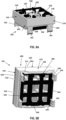
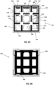
- Fig. 8A in a perspective view, shows a top housing part of a modular construction system light matrix viewed from above, the top housing part having a compartment grid arranged therein.
- Fig. 8B in a perspective view, shows the top housing part of Fig. 8A from below.
- the compartment grid 300 may comprise one or more flanges 350 extending downward from the compartment grid 300 arranged along side(s) of the compartment grid 300.
- the purpose of the one or more flanges 350 is to prevent light bleeding sideways from the compartments 330 at the level of the PCB and light bleeding downwards and through the sidewalls of the lower housing part 102.
- the compartment grid 300 comprise two flanges 350 arranged along opposite sides of the compartment grid 300.
- the bottom 340 of compartment grid 300 is in black color. This is chosen, so there would be black plastic and a black PCBA around the LEDs, which provides for limited light bleeding/optimizing the light containment.
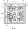
- Fig. 9A shows the modular construction system light matrix with the diffuser element removed, and illustrates light pattern in the light matrix.
- Fig. 9B in a sectional perspective view parallel to a side of the light matrix, shows the top housing part including a diffuser element, and illustrates light patterns in the light matrix;
- Fig. 9C in a sectional perspective view diagonally from corner to corner of the light matrix, shows the top housing part including a diffuser, and illustrates light patterns in the light matrix.
- the placement of the light emitting elements 210 have an impact on the light output.
- the light emitting elements 210 are moved as much as possible towards the center of the PCB 250 (illustrated by arrows in Fig. 9A ).
- the construction of the light reflecting internal walls 150 makes the limitation. With the optimized position, the center of the light emitting elements 210 have direct line towards the edge of the diffuser element 400. This way as much as possible of the emitted light with direction towards the edge of the diffuser elements enters the diffuser element (see arrows 700 in Fig. 9B and C ).
Landscapes
- Engineering & Computer Science (AREA)
- General Engineering & Computer Science (AREA)
- Physics & Mathematics (AREA)
- General Physics & Mathematics (AREA)
- Theoretical Computer Science (AREA)
- Microelectronics & Electronic Packaging (AREA)
- Illuminated Signs And Luminous Advertising (AREA)
- Devices For Indicating Variable Information By Combining Individual Elements (AREA)
- Non-Portable Lighting Devices Or Systems Thereof (AREA)
- Planar Illumination Modules (AREA)
- Led Device Packages (AREA)
Description
- The present invention relates to a modular construction system and a modular construction system light matrix.
- Modular construction systems as such are known in the art, as is various modular construction system units, for example motor units, for such modular construction systems etc. Modular construction systems comprises a plurality of construction elements, for example building blocks or bricks, which - when connected together-may be assembled to form a variety of different building structures. Motor units may be added to such modular construction systems in order to make parts of such system move. The present invention, a modular construction system light matrix, allows to provide a building structure formed from such construction elements, for example building blocks or bricks, frames, connectors, beams etc. with light output. For example, the modular construction system light matrixes according to the invention may be used to form eyes of a robot constructed from construction elements.
- Modular construction systems are "modular" in the sense that the construction elements making up the construction systems are sized and shaped and comprise cooperating connection means allowing their interconnection, such that models/sets, such as figures robots, etc. may be constructed.
- Learning systems, robotics construction sets, and so-called maker kits are known, which can provide a user with a variety of functionalities.
- Modular construction elements as they are known from traditional modular construction systems, such as beams, plates, bricks, pegs, connectors, cog-wheels, etc., may be combined with functional modular construction elements, such as lighting elements, motors/actuators, sensors, but also programmable processor units, which may also be digitally connectable with external devices, e.g. for programming or remote control. Such modular construction systems with enhanced functionality have proven their value in a play and/or learning context, not the least because they facilitate reliable, yet easily detachable mechanical connections between simple and functional modular construction elements, and because the functional modular construction elements are adapted to each other to provide a positive and stimulating user experience.
- Light matrices as such are known in the art. On example is shown in a video at the internet location https://learn.adafruit.com/sqaure-neopixel-display-with-black-led-acrylic; see especially from 2:15 to 2:38. Screen dumps from this video is shown in
Figs. 1A and 1B in the attached drawings. Although, this the video discusses the problem of light bleeding, the problem of light is not successfully solved in the light matrix shown. -
US 2005/128743 A1 discloses the preamble ofclaim 1. - Other examples of light matrixes are disclosed in
WO 95/18435 A1 US 4 254 453 ,US 2016/307496 A1 , andKR 2018 0001022 - The phenomenon "light bleeding" occurs, in situations where two or more light sources are arranged in the vicinity of each other, and light from one lights source "bleeds" through openings in a light source housing or through the housing itself and distorts or changes the visual appearance of the light from the other light source.
- It is clear that the problem may be solved using thick material dimensions or expensive light absorbing materials. However, such solutions are not always possible in small devices.
- The present invention alleviates some of these problems of the prior art.
- In a first aspect, the objects of the invention are achieved by a modular construction system light matrix comprising
- a housing having side walls, an end wall, and a front edge encircling a front opening of said housing opposite to said end wall;
- an array of light emitting elements arranged on a printed circuit board, the printed circuit board being arranged in said housing;
- a compartment grid arranged in said housing, and having compartment grid walls extending from said printed circuit board towards said front opening of the housing, and forming an array of compartments, one compartment for each light emitting element; and
- a light diffusing element arranged at said opening of the housing,
- wherein the diffuser element comprises a plurality of diffuser tiles, each diffuser tile covering a compartment of the compartment grid,
- wherein each diffuser tile has a front surface, a back surface and sidewalls formed perpendicularly to the front surface,
- wherein the diffuser element comprises a diffuser grid providing a barrier between mutually facing sidewalls of the diffuser tiles,
- wherein the diffuser grid is formed in a material different from a material of the diffuser tiles, and
- wherein a lower side of the diffuser grid is adapted to abut against an upper side of the compartment grid.
- Thereby, a very efficient prevention of light bleeding between compartments of the modular construction system light matrix and fields/sections of the diffuser element is achieved.
- Preferably, the diffuser tiles are made by a material capable of allowing light to pass there through while diffusing the light.
- The diffuser grid comprises first diffuser grid walls and intersecting second diffuser grid walls, and the first diffuser grid walls and intersecting second diffuser grid walls are aligned with the compartment grid walls of the compartment grid.
- In either case, the compartment grid may be made by a light absorbing material.
- In a further embodiment, the diffuser grid is made from a light absorbing material. Alternatively, the diffuser grid is made by a light reflecting material.
- In either case the diffuser grid may be formed in the same material as the side walls of the housing.
- In some embodiments, outwardly facing sidewalls of the diffuser tiles extend in front of said front edge and forms an extension of the sidewalls of the housing and flush therewith.
- Thereby, a visual effect of the fields of the diffuser element is also obtained in the sideways direction of the diffuser element and not just at the front.
- In some embodiments, each diffuser tile comprises a compartment portion extending into a compartment provided by the compartment grid.
- Thereby, a very efficient light bleeding prevention between the matrix fields is obtained, while at the same time the distribution of the light over the entire outer surface of the diffuser tiles is achieved.
- In an embodiment, outwardly facing surfaces of the compartment portion of the diffuser tiles arranged at external edges and corners of the diffuser element are angled relative to the outwardly facing sidewalls of the diffuser tiles. Thereby, it is achieved that light emitted from the light emitting elements is directed also towards the side walls of the diffuser tiles. Preferably, the angle between the side walls of the diffuser tiles and the corresponding outwardly facing surface is acute.
- In an embodiment, the compartment portion of the diffuser tiles formed at external corners of the diffuser element comprises a first surface formed between outwardly facing side surfaces at the external corners of the diffuser element, which first surface interconnects the two outwardly facing side surfaces of the compartment portion. Thereby, it is achieved that light emitted from the light emitting elements is directed also towards the corners of the diffuser element. Preferably, the first surface forms an angel of 45° relative to the two adjacent outwardly facing side surfaces.
- In further embodiments, the diffuser tiles are interconnected by tile connecting element formed integrally with and in the same material as the diffuser tiles.
- Thereby, it is made possible that the diffuser grid may be formed in spaces between the diffuser tiles as the second stage in a two stage moulding process (two component moulding process), where the diffuser tiles with the connecter elements are formed in the first stage of the two stage moulding process (two component moulding process). In an embodiment thereof, the connecting elements are protrusions extending from the lower surface of the diffuser tiles, at corners of the diffuser tiles, where four neighbouring diffuser tiles meet.
- In further embodiments, internal surfaces of the compartments of the compartment grid are covered by internal walls formed in a material different from the material of the compartment grid. The internal walls may be formed in a light reflecting material.
- In either case, in an embodiment, the internal walls are made from the same material as the sidewalls of the housing.
- In further embodiments, the internal walls are formed integral with the housing. For example, at least the sidewalls of the housing may be formed together with the internal walls in a second injection moulding stage of a two stage moulding process (two component moulding process), where a compartment grid formed in the first injection moulding stage of a two stage moulding process (two component moulding process) is used as core in the second injection moulding stage. In further embodiments, the internal walls taper outwards towards the diffuser element.
- Also, in any of the above mentioned embodiments, internal walls of the compartment grid may taper outwards towards the diffuser element.
- Also, in any of the above mentioned embodiments, outwardly facing sidewalls of the diffuser element may extend in front of said front edge and form an extension of the sidewalls of the housing and flush therewith.
- In further embodiments, the housing comprises connector openings complementary with connector pegs of a modular construction system.
- In a second aspect, the objects of the invention are obtained by a modular construction system light matrix comprising
- a housing having side walls, an end wall and a front edge encircling a front opening of said housing opposite to said end wall;
- an array of light emitting elements arranged on a printed circuit board, the printed circuit board being arranged in said housing;
- a compartment grid arranged in said housing, and having compartment grid walls extending from said printed circuit board towards said front opening of the housing, and forming an array of compartments, one compartment for each light emitting element; and
- a light diffusing element arranged at said opening of the housing,
- In an embodiment the modular construction system light matrix according to the second aspect,
- the diffuser element comprises a plurality of diffuser tiles, each diffuser tile covering a compartment of the compartment grid,
- wherein each diffuser tile has a front surface a back surface and sidewalls formed perpendicularly to the front surface,
- wherein the diffuser element comprises a diffuser grid providing a barrier between mutually facing sidewalls of the diffuser tiles,
- wherein the diffuser grid is formed in a material different from a material of the diffuser tiles, and
- wherein a lower side of the diffuser grid is adapted to abut against an upper side of the compartment grid.
- In further embodiments of the second aspect of the invention, the modular construction system light matrix according to the second aspect, may further comprise any of the further features of the embodiments, of the first aspect of the invention.
- It should be emphasized that the term "comprises/comprising/comprised of" when used in this specification is taken to specify the presence of stated features, integers, steps or components but does not preclude the presence or addition of one or more other features, integers, steps, components or groups thereof.
- In the following, the invention will be described in greater detail with reference to embodiments shown by the enclosed figures. It should be emphasized that the embodiments shown are used for example purposes only and should not be used to limit the scope of the invention.
-
Fig. 1A illustrates a prior art light matrix, showing components thereof in a disassembled state, a housing with an array of LED's and a compartment grid made in a dark plastic material; -
Fig. 1B shows further components of the prior art light matrix ofFig. 1A , a diffuser plate arranged in an upper frame; -
Fig. 2A , in a perspective view, shows a modular construction system light matrix according to the invention; -
Fig. 2B , also in a perspective view, shows the modular construction system light matrix from the rear or bottom side; -
Fig. 3 , in a perspective view, shows a modular construction system light matrix according to an embodiment of the invention, in a disassembled state; -
Fig. 4 , in a perspective sectional view, shows an upper portion of a modular construction system light matrix according to an embodiment of the invention; -
Fig. 5 , in a side sectional view, shows an upper portion of a modular construction system light matrix according to an embodiment of the invention in a section different than inFig. 4 ; -
Fig. 6A , in a perspective view, shows a diffuser element for a modular construction system light matrix according to an embodiment of the invention, and viewed from an inner/internal/bottom side thereof; -
Fig. 6B shows the diffuser element ofFig. 6A in a front view; -
Fig. 6C shows the diffuser element ofFig. 6A in a side view; -
Fig. 6D , in a perspective view, shows a section through the diffuser element ofFig. 6A ; -
Fig. 7A , in a perspective view, shows a bottom housing part of a modular construction system light matrix according to an embodiment of the invention, with an array of LEDs; -
Fig. 7B , in a perspective view, shows a top housing part of a modular construction system light matrix mounted on the bottom housing part ofFig. 7A ; -
Fig. 8A , in a perspective view, shows a top housing part of a modular construction system light matrix viewed from the side and above, the top housing part having a compartment grid arranged therein; -
Fig. 8B , in a perspective view, shows the top housing part ofFig. 8A from the side and showing a bottom side configured for facing the bottom housing part; -
Fig. 8C , in a top view, shows the top housing part ofFig. 8A from above; -
Fig. 8D , in a bottom view, shows the top housing part ofFig. 8A from below; -
Fig. 8E , in a perspective view, shows the top housing part ofFig. 8A from a side and slightly below; -
Fig. 8F , in a side view, shows the top housing part ofFig. 8A ; -
Fig. 9A , shows the modular construction system light matrix with the diffuser element removed, and illustrates light pattern in the light matrix; -
Fig. 9B , in a sectional perspective view parallel to a side of the light matrix, shows the top housing part including a diffuser element, and illustrates light patterns in the light matrix; and -
Fig. 9C , in a sectional perspective view diagonally from corner to corner of the light matrix, shows the top housing part including a diffuser, and illustrates light patterns in the light matrix. -
Figs. 1A-B show an example of a priorart light matrix 900, in a disassembled state to unveil components thereof.Fig. 1A shows a squarelower housing part 910 having aLED array 920 formed inside thelower housing part 910, and agrid 930 made in a dark plastic material and configured to form a compartment around each of theLEDs 925 of theLED array 920. The LEDs are arranged in a regular two-dimensional pattern on a surface of a plate 940 - presumably a printed circuit board, theplate 940 being mounted in thelower housing part 910. - In
Fig. 1A , thegrid 930 is disassembled from thelower housing part 910. InFig. 1B thegrid 930 is arranged in thelower housing part 910 and forming a compartment around each of theLEDs 925 of theLED array 920 and abutting on an upper surface of theplate 940. - Also shown in
Fig. 1B is anupper housing part 950 in the form of an upper frame 960 and adiffuser plate 970 arranged in the upper frame 960. Thediffuser plate 970 is a continuous unitary structure, made in a material suitable for diffusing light travelling through thediffuser plate 970. Thediffuser plate 970 is sized and shaped to cover an opening provided in and through a top surface - defined by a circumferential flange of the upper frame 950 -by fitting into theupper frame 950 and abutting on lower surface of the circumferential flange of theupper frame 950. - The
upper housing part 950 is sized and shaped to cooperate with thelower housing part 910 to form a closed, boxed shaped light matrix unit (not shown). - The
LEDs 925 of theLED array 920 may be of a type capable of emitting light in several colors or theLEDs 925 may each emit a different color. - The purpose of the
grid 930, which is made in a dark plastic material is to formcompartments 980 for eachLED 925, such that light from one compartment does not "bleed" into a neighboring compartment, and such that thecompartments 980 partitions the front surface of the diffuser plate into an array of square fields, which may show different colors in neighboring fields with light from one field "bleeding" into, and influencing the light in another square fields. As mentioned above, this is not always successfully achieved, as the diffuser plate material "draws" light from one compartment to another. - Turning now to the present invention,
Fig. 2A , in a perspective view, shows a modular construction systemlight matrix 1 according to some embodiments of the invention.Fig. 2B , also in a perspective view, shows the modular construction system light matrix from the rear or bottom side.Fig. 3 , also in a perspective view, shows an embodiment of the modular construction systemlight matrix 1, in a disassembled state. - The modular construction system light matrix 1 - hereinafter called a light matrix 1 - comprises a
housing 100, anarray 200 comprising a plurality oflight emitting elements 210 arranged within thehousing 100, alight diffusing element 400, and acompartment grid 300, arranged in thehousing 100 between thearray 200 of light emittingelements 210 and thelight diffusing element 400. - The
housing 100 may - as shown - comprise anupper housing part 101 and alower housing part 102, where theupper housing part 101 and thelower housing part 102 are interconnectable to form thecomplete housing 100. - The plurality of
light emitting elements 210 may be arranged on a 2D grid such as a grid defining, for example, a rectangle, a square, a circle, etc. If the grid is in a rectangular or square shape, the light matrix may be a square matrix, i.e. have the same number oflight emitting elements 210 in its rows and columns, e.g. a 2x2, 3x3, 4x4, etc. However, in other embodiments, the number of rows and columns oflight emitting elements 210 may differ. The separatelight emitting elements 210 may be Light Emitting Diodes (LEDs), and they may be of the same type and/or model, or different. - The colour and/or the intensity of each of the
light emitting elements 210 may be controlled individually, such that some or all of the light emitting elements may be on or off at a given time. - The
light matrix 1 can receive digital information and preferably is provided with processing power to decode digital information to regulate the colour and intensity of each of the light emitting elements, for example as requested directly by a user or by a software program. By "regulating" is meant that the colour and intensity is set appropriately, i.e. the colour may be changed, the intensity may be increased or decreased, or the light turned off (intensity = zero). - Preferably, the
array 200 of light emittingelements 210 may as shown be regular 3×3 array (orthogonally arranged in 3 rows and 3 columns) oflight emitting elements 210, i.e. with a total of 9light emitting elements 210. - The
light emitting elements 210 are preferably - and as shown in e.g.Fig. 3 - mounted on a printed circuit board (PCB) 250. - Normally, PCB's are formed in a green material. This material however is quite transparent to light. In order to reduce this source of light bleeding through the
housing 100, such as the back side of the housing orlower housing part 102, in preferred embodiments, a black - more light absorbing - PCB material is chosen. - The control for regulating the
light emitting elements 210 may be provided as components on thePCB 250. - The
light matrix 1 may further comprise electronic components, such as electronic control components, an energy source (e.g. a battery package), etc. Preferably, any such further electronic components are provided in thelower housing part 101 or on thePCB 250, preferably on the back side of the PCB. - The
light matrix 1 may further comprise means for communicating with external devices or a user. For example control input for thelight emitting elements 210 may be provided from an external device being in wireless communication (not shown) with thelight matrix 1. In other embodiments, and as shown inFigs. 2A, 2B and3 , thelight matrix 1 may comprises acable unit 800 comprising one or moreelectrical cables 810 and aconnector plug 820 configured for connecting thelight matrix 1 with an external device. Thereby, information (control signals) and/or energy (electrical) may be transferred to thelight matrix 1 from the (not shown) external device. - In an embodiment - and as shown throughout the figures - the
housing 100 preferably has a quadratic cross section, when thearray 200 of light emittingelements 210 is an n×n array. - As mentioned above, the
housing 100 may comprise two parts, anupper housing part 101 and alower housing part 102. It will however be appreciated that the housing may - in not shown embodiments - be formed as a single part. In yet other embodiments the housing may comprise more than two parts. - In any case the
housing 100 is preferably a box-shaped structure having a set ofside walls 110 and preferably a bottom wall/end wall 110. Thus, at least a portion of thehousing 100 has the shape of an open box before mounting of other components. In embodiments, where thehousing 100 comprises anupper housing part 101 and alower housing part 102, each of thesidewalls 110 has a wall portion being defined on theupper housing part 101 and a wall portion defined on thelower housing part 102. In this case the bottom wall/end wall 110 is provided by thelower housing part 102, and thelower housing part 102 has the shape of an open box before mounting of other components. Theupper housing part 101, in this case is a tubular structure, havingsidewalls 110 and open upper and lower ends (before mounting of other components. The sidewalls of theupper housing part 101 and thesidewalls 110 of thelower housing part 102 are configured to cooperate, such that when theupper housing part 101 and thelower housing part 102 are assembled, they collectively form thehousing 100. - The
side wall 110 of the housing 100 - and thereby the housing 100 - has an upper edge orfront edge 130, which encircles an upper or front opening 140 of thehousing 100. The front opening 140 is arranged opposite to saidend wall 120 in thehousing 100. - In the embodiments shown herein, the upper edge or
front edge 130 and the upper or front opening 140 are provided on theupper housing part 101. - The above mentioned
light diffusing element 400 is arranged on and connectable to thehousing 100, such that thelight diffusing element 400 covers the front opening 140. In some embodiments, and as shown in e.g.Figs 4 and5 , a lower or downwardly facingedge 470 of thelight diffusing element 400 is configured to rest on thefront edge 130 of thehousing 100. In other, not shown, embodiments a light diffusing element for example as shown in the figures, and described below in connection withFigs. 6A-D may alternatively be configured to be located between internally facing sides of the sidewalls of the housing or an upper housing part thereof. - In the embodiments shown herein, the
light diffusing element 400 covers the front opening 140 provided in theupper housing part 101, and the lower or downwardly facingedge 470 of thelight diffusing element 400 is configured to rest on thefront edge 130 of theupper housing part 101 of thehousing 100. Thereby, thediffuser element 400 and thehousing 100 can be configured such that the sidewalls 440 of thediffuser element 400 are flush with thesidewall 110 of thehousing 100, as shown in e.g.Fig. 2A . - As mentioned above, the
light matrix 1 comprises acompartment grid 300. Thecompartment grid 300 may be formed in a light absorbing material. In some embodiments thecompartment grid 300 may be made in a black polymer material. - The
compartment grid 300 is arranged within thehousing 100. Thecompartment grid 300 comprises grid walls (may also be called compartment grid walls), two or more firstcompartment grid walls 310, and two or more a second set of firstcompartment grid walls 320. The firstcompartment grid walls 310 are arranged in parallel to each other. The secondcompartment grid walls 320 are arranged in parallel to each other. The firstcompartment grid walls 310 are arranged perpendicular to the secondcompartment grid walls 320. Thus, the firstcompartment grid walls 310 and the secondcompartment grid walls 320 intersect, and form compartments 330 between them. - Preferably, the
compartment grid 300 is configured, such that onecompartment 330 is provided for each light emittingelement 210 of thearray 200 of light emittingelements 210. - The
compartment grid 300 is further configured such that the compartment grid walls/grid walls compartment grid 300 to extend from the surface (such as the upper/upwardly facing surface of a PCB 250) on which thelight emitting elements 210 are arranged, and towards said front opening 140 of thehousing 100, such as to a bottom/lower/downwardly facing surface of thelight diffusing element 400, as shown in e.g.Fig. 4 and5 . - In some embodiments, and as shown in
Fig. 3 , thecompartment grid 300 may be an individual element which is mounted within thehousing 100 during an assembly stage of manufacturing thelight matrix 1. - However, in other embodiments, and as described in further detail below, the
compartment grid 300 may be formed together with thehousing 100, for example in a two stage injection moulding process (two component moulding process). - In the embodiment shown in
Fig. 3 , thecompartment grid 300 has two firstcompartment grid walls 310 and two intersecting secondcompartment grid walls 320 forming a grid or array of ninecompartments 330, in a 3×3 array, where only thecentral compartment 330 is closed on all sides, and where the eightcompartments 330 formed along the perimeter of thecompartment grid 300 are open in the sense that these compartment have an externally facing side, facing an inner surface of the housing side walls 110 (when assembled), which is not covered by a wall. - It will be appreciated, that in some embodiments also a "loose"
compartment grid 300 as shown inFig. 3 may have firstcompartment grid walls 310 and secondcompartment grid walls 320 formed along and facing the inner surface of the housing side walls 110 (when assembled), such that all of thecompartment 330 are closed sideways. - In embodiments shown in
Figs. 4 ,5 ,7A, 7B ,8A-F , and9A-C , thecompartment grid 300 comprises firstcompartment grid walls 310 and secondcompartment grid walls 320 formed along and facing the inner surface of thehousing side walls 110, such that all of thecompartment 330 are closed sideways. In this embodiment, thecompartment grid 300 has four firstcompartment grid walls 310 and four intersecting secondcompartment grid walls 320 forming a grid or array of ninecompartments 330, in a 3×3 array, where all the compartments are closed on all sides. - The
housing 100 is provided with at least onemodular connector 600 for connecting thelight matrix 1 to another construction element of a modular construction system. In the embodiments illustrated in the figures, seeFigs. 2A-B ,3 , and7A-B , thehousing 100 is provided with six suchmodular connectors 600, two in theend wall 120, and two in each of twoopposed side wall 110 of thehousing 100. In these embodiments themodular connectors 600 are provided in thelower housing element 102. In other embodiments there may be fewer or moremodular connectors 600. In other embodiments one or more connectors may be provided in theupper housing part 101 also. Themodular connectors 600 are formed as indentions into and through thehousing 100. The connectors are preferably connector openings. Preferably, the one or moremodular connectors 600 are configured for cooperating with and connecting to various types of construction elements of a modular construction. An example of a construction system having such connectors is known in the art, e.g. under the trade name LEGO TECHNIC ©, marketed by LEGO A/S. - Now returning to the
compartment grid 300, embodiments thereof are shown in more detail in e.g.Fig. 4. Fig. 4 , in a perspective sectional view, shows an upper portion of a modular construction system light matrix according to an embodiment of the invention. The section is taken along a side wall of thelight matrix 1housing 100. - In some embodiments the
compartment grid 300 is formed in a light absorbent material. In some embodiments thecompartment grid 300 is formed in in a polymer material. Preferably, thecompartment grid 300 is formed in a polymer material suitable for injection moulding. In some embodiments, thecompartment grid 300 is formed in a black polymer material. Such a material may be black colored ABS plastic, which has high light absorption properties and low light reflection properties. This help containing the light and stopping it from traveling between thecompartments 330, and through the outermostcompartment grid walls housing 100. - The
housing 100 or at least theupper housing portion 101 may be formed in a reflective polymer material, and preferably in a polymer material suitable for use in an injection moulding process. - In some embodiments, and as described in further detail below, the
housing 100, or at least theupper housing part 101 thereof may further comprisesinternal walls 150, see e.g.Fig. 4 , also made in a light reflecting material. This material may be the same as used for thehousing 100 as such. In such cases, the black ABS plastic material (or materials with similar properties) of thecompartment grid 300 prevents the light from zig zagging between white reflective and the black parts and between the (black)PCB 250 and theblack compartment grid 300. - In all embodiments described above and below, preferably the
diffuser element 400 and thecompartment grid 300 are assembled, to avoid air gaps there between. In practice such airgaps may not be possible to eliminate entirely, for example due to production tolerances. In such cases the black or other light absorbent properties of thecompartment grid 300 may secure that, where at the few places where there are airgaps between the upper edge of the reflecting inner walls and the diffuser element, it is secured, that thecompartment grid 300 is always on one side of these airgaps. This limits the amount the light that can "zig-zag" between the parts, and thereby the light bleeding between thecompartments 330 and betweencompartments 330 and thesidewalls 110 of thehousing 100. -
Fig. 5 , in a side sectional view, shows the upper portion of a modular construction system light matrix according to the same embodiment of the invention asFig.4 , but in a section different than inFig. 4 . - Turning now to the
diffuser element 400, preferred embodiments are illustrated inFigs. 6A-D . - Portions of the
diffuser element 400 is preferably formed in a material capable of allowing light to pass there through while diffusing the light, or a transparent material treated to give light diffusing properties. - In an embodiment the
diffuser element 400 comprises a plurality ofdiffuser tiles 410. Adiffuser tile 410 is provided for eachcompartment 330 of thecompartment grid 300, and covers thecompartment 330 with which it is associated. - In embodiments, where the
diffuser element 400 comprises a plurality ofdiffuser tiles 410, the diffuser tiles are preferably formed in a material capable of allowing light to pass there-through while diffusing the light, or a transparent material treated to give light diffusing properties. - In the embodiments shown in the figures, there are 9
diffuser tiles 410 arranged in a 3×3 regular array. However, generally, the diffuser element is provided such that there is adiffuser tile 410 for each light emittingelement 210. Similarly, the above mentionedcompartment grid 300 is manufactured such that there is one compartment for each light emittingelement 210. - Each of the
diffuser tiles 410 comprises afront surface 420, aback surface 430 and sidewalls 440. - The
front surface 420 and theback surface 430 are formed parallel to each other. - The sidewalls 440 of a
diffuser tile 410 are formed perpendicularly to thefront surface 420. - Because the
diffuser tiles 410 are arranged in a regular, two-dimensional array, some of the sidewalls 440 of thediffuser tiles 410 will face the sidewalls 440 of the neighbouringdiffuser tiles 410, i.e. they have mutually facingsidewalls 442, while thediffuser tiles 410 formed along edges of thediffuser element 400 also have outwardly facingsidewalls 442, i.e. sidewalls not facingother diffuser tiles 410. - As shown, the
diffuser element 400 comprises adiffuser grid 500 providing a barrier between the mutually facingsidewalls 442 of thediffuser tiles 410. - This
diffuser grid 500 is preferably formed in a material different from a material of thediffuser tiles 410. - The
diffuser grid 500 comprises an array of diffuser grid walls, firstdiffuser grid walls 510 and intersecting seconddiffuser grid walls 520. The firstdiffuser grid walls 510 and intersecting seconddiffuser grid walls 520 are aligned with thecompartment grid walls compartment grid 300, when thediffuser element 400 is assembled with the housing and the compartment grid. Preferably, thecompartment grid 300 and thediffuser element 400 are also assembled such that thediffuser grid walls compartment grid walls compartments 330 and the square light fields or zones provided by thediffuser tiles 410 is minimized or even prevented. - So, a lower side (or at least a portion thereof) of the
diffuser grid 500 is adapted to abut against an upper side (or at least a portion thereof) of thecompartment grid 300. This means that thecompartment grid 300 and thediffuser grid 500 are separate entities, that when thelight matrix 1 is assembled abuts against each other. - In some embodiments, and as exemplified below, the
diffuser grid 500 and the diffuser tiles are formed together as a single unit, for example in a two stage moulding process. - In some embodiments, the
diffuser grid 500 is formed in a light absorbing material. However, in alternative embodiments thediffuser grid 500 is formed in a light reflecting material. - In some embodiments, the
diffuser grid 500 may be formed in the same material as thehousing 100, or at least the same material as theside walls 110 of thehousing 100. - In some embodiment, and as shown in for example
Figs. 4 and5 , the outwardly facingsidewalls 441 of thediffuser element 400 and in embodiments, where thediffuser element 400 comprisesdiffuser tiles 410, the outwardly facingsidewalls 441 of thediffuser element 400/diffuser tiles 410 extend in front of or above thefront edge 130, such that the outwardly facingsidewalls 441 of thediffuser element 400/diffuser tiles 410 form an extension of thesidewalls 110 of thehousing 100 in the plane of thesidewalls 110 of thehousing 100. The outwardly facingsidewalls 441 of thediffuser element 400/diffuser tiles 410, are preferably arranged such that they are flush with thesidewalls 110 of thehousing 100. - In such embodiments, it is secured that light in a square light field or zone defined by the
compartment 330, is visible also to the side (perpendicularly to thesidewalls 110 of the housing 100). - It will be appreciated, that in principle a
diffuser element 400 as described above, may - alternatively to being arranged to extend in front of thefront edge 130 of the housing 100 - be arranged in the front opening 140 of thehousing 100, with thesidewalls 110 of thehousing 100 covering the outwardly facingsidewalls 441 of thediffuser element 400/diffuser tiles 410. - In either of the above embodiments, the each
diffuser tile 410 may comprise amain body part 415 and acompartment portion 460 extending downwards from themain body part 415. This downwardly extendingcompartment portion 460 is configured for extending into acompartment 330 provided by thecompartment grid 300. This may be appreciated fromFig. 4 or5 . - On the
diffuser tiles 410 being arranged along the edges of the diffuser element 400 (i.e. diffuser tiles 412) and on thediffuser tiles 400 being arranged in the corners of the diffuser element 400 (diffuser tiles 411), themain body part 415 of thediffuser tiles 410, 411, 412 may comprise a downwardly facingedge 470 orsurface 470 formed as a ledge between themain body part 415 and thecompartment portion 460. This downwardly facingedge 470 may be configured for abutment on thefront edge 130 of the housing 100 (in embodiments where thediffuser element 400 extend in front of the housing), or on an upper edge of the compartment grid 300 (in embodiments, where thediffuser element 400 is framed by thesidewalls 110 of the housing 100). - As shown in e.g.
Fig. 6a and6D , thediffuser tiles 410, or themain body part 415 are generally square (seen in a cross section parallel to the upper/upwardly facingsurface 420 of the diffuser tiled 410. - As also shown in e.g.
Fig. 6a and6D , thecompartment portion 460 of thediffuser tiles 410 is also generally square (seen in a cross section parallel to the upper/upwardly facingsurface 420 of the diffuser tiled 410). However, dependent on the diffuser tile being arranged at a corner of the diffuse element 400 (diffuser tiles 411) or at a side edge (diffuser tiles 412) or inside the array (diffuser tiles 413), thecompartment portion 460 may be placed differently relative to themain body part 415. - The
compartment portion 460 of adiffuser tile 410 have side surfaces. Some of the side surfaces 462 of thecompartment portion 460 face towardscompartment portion 460 of a neighbouringdiffuser tile 410. Thecompartment portion 460 formed on diffuser tiles 411, 412 formed at external edges and corners of thediffuser element 400 have outwardly facing surfaces 461. - In some embodiments (in particular where the
diffuser element 400 extend in front of the housing 100), the outwardly facingsurfaces 461 of thecompartment portion 460 of the diffuser tiles 411, 412 formed at external edges of thediffuser element 400 comprises, are angled relative to the outwardly facingsidewalls 441 of thediffuser tiles 410. Thereby, it is achieved that light emitted from thelight emitting elements 210 is also directed towards theside walls 441 of the diffuser tiles 411. In preferred embodiments, the angle between theside walls 441 of the diffuser tiles 411 and the corresponding outwardly facing surface is acute. - As may be appreciated from
Figs. 6a and6C , thecompartment portion 460 of thediffuser tiles 410, 411 formed at external corners of thediffuser element 400 may comprises afirst surface 465 formed between outwardly facing side surfaces 461 at the external corners of thediffuser element 400. Thefirst surface 465 interconnects the two outwardly facing side surfaces 461 of thecompartment portion 460. - A
first surfaces 465 directs light emitted from thelight emitting elements 210 and through thediffuser tile 410 and towards the corresponding corner of thediffuser element 400. Preferably thefirst surface 465 forms an angel of 45° relative to the two adjacent outwardly facing side surfaces 461. - In some embodiments the
diffuser tiles 410 of thediffuser element 400 may be formed as separate pieces and connected to form thediffuser element 400, by for example thediffuser grid 500, or other (not shown) connecter elements. - However, in preferred embodiments, and as shown in e.g.
Figs. 6A ,6C, and 6D , thediffuser element 400 comprisingdiffuser tiles 410 and thediffuser grid 500 is formed as one integrated unit. In some embodiments, this may be achieved by thediffuser tiles 410 of thediffuser element 400 being interconnected bytile connecting elements 450 formed integrally with and in the same material as thediffuser tiles 410. - Thereby, it is made possible, that the
diffuser grid 500 may be formed in the spaces between thediffuser tiles 410 as the second stage of a two stage moulding process (two component moulding process), where thediffuser tiles 410 with theconnecter elements 450 are formed in the first stage of the two stage moulding process (two component moulding process).Alternatively, thediffuser grid 500 may be formed in a first stage of a two stage moulding process (two component moulding process), and theinterconnected diffuser tiles 410 may be formed in the second stage. - In some embodiments, and as shown in e.g.
Figs. 6A ,6C, and 6D , the connectingelements 450 are protrusions extending from thelower surface 430 of thediffuser tiles 410, at corners of thediffuser tiles 410, where four neighbouringdiffuser tiles 410 meet. -
Fig. 6A , in a perspective view, shows adiffuser element 400 for a modular construction system light matrix according to an embodiment of the invention, and viewed from an inner/internal/bottom side thereof, the diffuser element having ninediffuser tiles 410 formed in a regular two-dimensional array. In this case, thediffuser element 400 have four connectingelements 450, that connects thenines diffuser tiles 410. Two of the four connectingelements 450 are solid, and the other two of the four connectingelements 450 have acircular holes 451 in the center forming inlet points for injection moulding thediffuser grid 500 in the second shot/stage of a two component injection moulding process. The connectingelements 450 enables that thediffuser element 400 can be moulded with two inlets instead of nine inlets, which is very beneficial on such small injection moulded plastic parts. - Above it was mentioned, that is some embodiments the internal surfaces of the
compartments 330 of thecompartment grid 300 may be covered byinternal walls 150. Now this will be explained in further detail with reference toFigs. 4 ,5 and8A-F . - First, it is noted that these
internal walls 150 may be formed in a material different from the material used forcompartment grid 300. - Preferably, the
internal walls 150 are formed in a light reflecting material. - In either case, in an embodiment, the
internal walls 150 may be made from the same material as thehousing 100, or at least as thesidewalls 110 of thehousing 100. - In some embodiments (not shown), the
internal walls 150, the housing 100 (or at least as thesidewalls 110 of the housing 100) and thecompartment grid 300 may be formed as separate, individual parts and be assembled subsequently. - In other embodiments (not shown),
internal walls 150 may be provided as a layer made on thecompartment grid 300 after the formation thereof, for example by coating the internal sides of thecompartment grid 300 using a suitable material. - However, in preferred embodiments, the
internal walls 150 are formed integral with thehousing 100. For example, at least thesidewalls 110 of thehousing 100 may be formed together with theinternal walls 150 in a second injection moulding stage of a two stage moulding process (two component moulding process), where acompartment grid 300 formed in the first injection moulding stage of a two stage moulding process (two component moulding process) is used as a core in the second injection moulding stage. - As shown in
Figs. 4 ,5 and8C , at least some of theinternal walls 150 and/or the inwardly facing surfaces of thecompartments 330 may be configured such that they taper outwards in a direction from thelight emitting elements 210 at the bottom of thecompartments 330 and towards thediffuser element 400 at thefront edge 130 of thehousing 100. -
Figs. 4 and5 show an upper part of thehousing 100, with theupper housing part 101 of the housing and the arrangement of thecompartment grid 300 and the PCB 250 (with the light emitting elements 210) relative thereto. However, portions of thelower housing part 102 is also visible in bothFig. 4 and5 . As shown most clearly inFig 5 , theupper housing part 101 may comprise a slightly recessed (relative to the outer surface of theside wall 110 of the upper housing part 101), downwardly extendingflange 111 configured for cooperating with aflange 112 upwardly extending from thelower housing part 102. - As may be best appreciated from
Figs 8A , B, E, and F, theupper hosing part 101 may further comprise downwardly extending flexible/resilient legs 160. In the shown embodiment, theupper hosing part 101 comprises fourlegs 160. Abarb 165 is provided on eachleg 160. Anopening 170 is formed in and through asidewall 110 of thelower housing part 102, whichopening 170 is configured for receiving thebarb 165 of acorresponding leg 160 extending downward fromupper housing part 101. Thebarb receiving opening 170 is shown in e.g.Fig. 2A . The resilience of theleg 160 ensures that thebarb 165 may snap into thebarb receiving opening 170. By pressing thebarb 165 inwardly, theupper housing part 101 and thelower housing part 102 may be released from each other again. -
Fig. 7A , in a perspective view, shows a bottom housing part of a modular construction system light matrix according to an embodiment of the invention, with an array of LEDs. -
Fig. 7B , in a perspective view, shows a top housing part of a modular construction system light matrix mounted on the bottom housing part ofFig. 7A . - Together,
Figs. 7A and 7B illustrates steps of the assembly of a light matrix according to the invention. - First in
Fig. 7A the electronic components of thelight matrix 1 are assembled in thelower housing part 102. Thecable unit 800 is connected to thePCB 250 with thelight emitting elements 210. ThePCB 250 with thelight emitting elements 210 is arranged in the lower housing part 201 with thelight emitting elements 210 facing upwards. - Then the
upper housing part 101 is connected to thelower housing part 102 to form the assembledhousing 100 of thelight matrix 1, as shown inFig. 7B . - Preferably, but not shown in
Figs 7A and 7B , thediffuser element 400 is also mounted to the top/upper housing part 101 before connecting theupper housing part 101 to thelower housing part 102. - The
diffuser element 400 may be first ultra-sonic welded onto the top/upper housing part 101. Then, the combineddiffuser element 400 and top/upper housing part 101 may then be snapped onto the bottom/lower housing part 102. - The top/
upper housing part 101 could also be called "light reflector housing". -
Fig. 8A , in a perspective view, shows a top housing part of a modular construction system light matrix viewed from above, the top housing part having a compartment grid arranged therein.Fig. 8B , in a perspective view, shows the top housing part ofFig. 8A from below. - As illustrated in
Figs. 8B ,8E and 8F , thecompartment grid 300 may comprise one ormore flanges 350 extending downward from thecompartment grid 300 arranged along side(s) of thecompartment grid 300. The purpose of the one ormore flanges 350 is to prevent light bleeding sideways from thecompartments 330 at the level of the PCB and light bleeding downwards and through the sidewalls of thelower housing part 102. - In
Figs. 8B ,8E and 8F , thecompartment grid 300 comprise twoflanges 350 arranged along opposite sides of thecompartment grid 300. - The
bottom 340 ofcompartment grid 300 is in black color. This is chosen, so there would be black plastic and a black PCBA around the LEDs, which provides for limited light bleeding/optimizing the light containment. -
Fig. 9A , shows the modular construction system light matrix with the diffuser element removed, and illustrates light pattern in the light matrix.Fig. 9B , in a sectional perspective view parallel to a side of the light matrix, shows the top housing part including a diffuser element, and illustrates light patterns in the light matrix; andFig. 9C , in a sectional perspective view diagonally from corner to corner of the light matrix, shows the top housing part including a diffuser, and illustrates light patterns in the light matrix. - The placement of the
light emitting elements 210 have an impact on the light output. Thelight emitting elements 210 are moved as much as possible towards the center of the PCB 250 (illustrated by arrows inFig. 9A ). - The construction of the light reflecting
internal walls 150 makes the limitation. With the optimized position, the center of thelight emitting elements 210 have direct line towards the edge of thediffuser element 400. This way as much as possible of the emitted light with direction towards the edge of the diffuser elements enters the diffuser element (seearrows 700 inFig. 9B andC ). - It is to be noted that the figures and the above description have shown the example embodiments in a simple and schematic manner. Many of the specific mechanical details have not been shown since the person skilled in the art should be familiar with these details and they would just unnecessarily complicate this description. For example, the specific materials used and the specific injection moulding procedure have not been described in detail since it is maintained that the person skilled in the art would be able to find suitable materials and suitable processes to manufacture the container according to the current invention.
-
- 1
- light matrix/modular construction system light matrix
- 100
- housing of light matrix
- 101
- upper housing part
- 102
- lower housing part
- 110
- side wall of housing
- 111
- downwardly extending flange of upper housing part
- 112
- upwardly extending flange of lower housing part
- 120
- end wall of housing
- 130
- front edge of housing
- 140
- front opening of housing
- 150
- internal walls
- 160
- leg extending downward from upper housing part
- 165
- barb on leg extending downward from upper housing part
- 170
- opening in lower housing part, configured for receiving barb of leg extending downward from upper housing part
- 200
- array/array of light emitting elements
- 210
- light emitting element such as light emitting diode (LED)
- 250
- printed circuit board (PCB)
- 300
- compartment grid,
- 310
- first compartment grid wall of compartment grid
- 320
- second compartment grid wall of compartment grid
- 330
- compartment formed between grid walls of the compartment grid
- 350
- flange extending downward from compartment grid
- 400
- light diffusing element/diffuser element
- 410
- diffuser tile
- 411
- diffuser tile at corners of light diffusing element/diffuser element
- 412
- diffuser tile at edges of light diffusing element/diffuser element
- 413
- diffuser tile at internal array positions of the light diffusing element
- 415
- main body part of the diffuser tiles
- 420
- front surface of the diffuser tile
- 430
- back/rear surface of the diffuser tile
- 440
- sidewall of the diffuser tile, formed perpendicularly to the front surface of the of diffuser tile
- 441
- outwardly facing sidewalls of the diffuser tile
- 442
- sidewall of the diffuser tile facing a sidewall of another diffuser tile
- 450
- tile connecting element, element connecting diffuser tiles of the diffuser element
- 460
- compartment portion of a diffuser tile
- 461
- outwardly facing surfaces of the compartment portion of diffuser tiles formed at external edges and corners of the diffuser element
- 462
- side surfaces of the compartment portion facing towards compartment portion of a neighbouring diffuser tile
- 465
- first surface formed between outwardly facing side surfaces at the external corners of the diffuser element
- 470
- downwardly facing edge
- 500
- diffuser grid/grid of the diffuser element
- 510
- first diffuser grid wall of diffuser grid
- 520
- second diffuser grid wall of diffuser grid
- 600
- modular connector, such as a connector hole
- 800
-
cable unit 800 - 810
-
electrical cables 810 - 820
- connector plug configured for connecting the light matrix with an external device
- 900
- prior art art light matrix
- 910
- lower housing part of prior art art light matrix
- 920
-
LED array 920 of prior art art light matrix - 925
- LED of prior art art light matrix
- 930
- grid of prior art art light matrix
- 940
- plate of prior art art light matrix
- 950
- upper housing part of prior art art light matrix
- 960
- upper frame of prior art art light matrix
- 970
- diffuser plate of prior art art light matrix
- 980
- compartments of prior art art light matrix
Claims (17)
- A modular construction system light matrix (1) comprising- a housing (100) having side walls (110), an end wall (120) and a front edge (130) encircling a front opening (140) of said housing (100) opposite to said end wall (120);- an array (200) of light emitting elements (210) arranged on a printed circuit board (250), the printed circuit board (250) being arranged in said housing (100);- a compartment grid (300) arranged in said housing (100), and having compartment grid walls (310, 320) extending from said printed circuit board (250) towards said front opening (140) of the housing (100), and forming an array of compartments (330), one compartment (330) for each light emitting element (210); and- a light diffusing element (400) arranged at said opening (140) of the housing (100),wherein the diffuser element (400) comprises a plurality of diffuser tiles (410), each diffuser tile (410) for covering a compartment (330) of the compartment grid (300),wherein each diffuser tile (410) has a front surface (420), a back surface (430) and sidewalls (440) formed perpendicularly to the front surface (420),wherein the diffuser element (400) comprises a diffuser grid (500) providing a barrier between mutually facing sidewalls (442) of the diffuser tiles (410),wherein the diffuser grid (500) is formed in a material different from a material of the diffuser tiles (410), characterised in thata lower side of the diffuser grid (500) is adapted to abut against an upper side of the compartment grid (300).
- A modular construction system light matrix (1) according to claim 1, wherein the compartment grid (300) is formed in a light absorbing material.
- A modular construction system light matrix (1) according to claim 1 or 2, wherein the diffuser grid (500) is formed in a light absorbing material.
- A modular construction system light matrix (1) according to claim 1 or 2, wherein the diffuser grid (500) is formed in a light reflecting material.
- A modular construction system light matrix (1) according to claim 4, wherein the diffuser grid (500) is formed in the same material as the side walls (110) of the housing (100).
- A modular construction system light matrix (1) according to any one of the claims 1-5, wherein outwardly facing sidewalls (441) of the diffuser tiles (410) extend in front of said front edge (130) and forms an extension of the sidewalls (110) of the housing (100) and flush therewith.
- A modular construction system light matrix (1) according to any one of the claims 1-6, wherein the each diffuser tile (410) comprises a compartment portion (460) extending into a compartment (330) provided by the compartment grid (300).
- A modular construction system light matrix (1) according to claim 7, wherein outwardly facing surfaces (461) of the compartment portion (460) of the diffuser tiles (410, 411, 412) formed at external edges of the diffuser element (400) are angled relative to the outwardly facing sidewalls (441) of the diffuser tiles (410).
- A modular construction system light matrix (1) according to claim 7 or 8, wherein the compartment portion (460) of the diffuser tiles (410, 411) formed at external corners of the diffuser element (400) comprises a first surface (465) formed between outwardly facing side surfaces (461) at the external corners of the diffuser element (400), which first surface interconnects the two outwardly facing side surfaces (460) of the compartment portion (460).
- A modular construction system light matrix (1) according to any one of the claims 1-9, wherein the diffuser tiles (410) are interconnected by tile connecting element (450) formed integrally with and in the same material as the diffuser tiles (410).
- A modular construction system light matrix (1) according to any one of the claims 1-10, wherein internal surfaces of the compartments (330) of the compartment grid (300) are covered by internal walls (150) formed in a material different from the material of the compartment grid (300).
- A modular construction system light matrix (1) according to claim 11, wherein the internal walls (150) are formed in a light reflecting material.
- A modular construction system light matrix (1) according to claim 11 or 12, wherein the internal walls (150) are formed integral with the housing (100).
- A modular construction system light matrix (1) according to any one of the claims 11-13, wherein the internal walls (150) taper outwards towards the diffuser element (400).
- A modular construction system light matrix (1) according to any one of the claims 1-14, wherein the diffuser element (400) comprising the diffuser grid (500) and the diffuser tiles (410) are formed integrally as a unit, mountable on the housing (100).
- A modular construction system light matrix (1) according to any one of the claims 1-15, wherein the housing (100) comprises connector openings (600) complementary with connector pegs of a modular construction system.
- A modular construction system light matrix (1) according to any one of the claims 1-16,
wherein outwardly facing sidewalls (441) of the diffuser element (400) extend in front of said front edge (130) and forms an extension of the sidewalls (110) of the housing (100) and flush therewith.
Applications Claiming Priority (2)
| Application Number | Priority Date | Filing Date | Title |
|---|---|---|---|
| DKPA202170132A DK181332B1 (en) | 2021-03-25 | 2021-03-25 | Modular construction system light matrix |
| PCT/EP2022/057723 WO2022200479A1 (en) | 2021-03-25 | 2022-03-24 | Modular construction system light matrix |
Publications (2)
| Publication Number | Publication Date |
|---|---|
| EP4315306A1 EP4315306A1 (en) | 2024-02-07 |
| EP4315306B1 true EP4315306B1 (en) | 2025-02-19 |
Family
ID=81386490
Family Applications (1)
| Application Number | Title | Priority Date | Filing Date |
|---|---|---|---|
| EP22718598.0A Active EP4315306B1 (en) | 2021-03-25 | 2022-03-24 | Modular construction system light matrix |
Country Status (10)
| Country | Link |
|---|---|
| US (1) | US12336064B2 (en) |
| EP (1) | EP4315306B1 (en) |
| JP (1) | JP2024515470A (en) |
| KR (1) | KR20230160865A (en) |
| CN (1) | CN115127082A (en) |
| BR (1) | BR112023019313A2 (en) |
| DK (1) | DK181332B1 (en) |
| IL (1) | IL307183A (en) |
| MX (1) | MX2023011223A (en) |
| WO (1) | WO2022200479A1 (en) |
Families Citing this family (1)
| Publication number | Priority date | Publication date | Assignee | Title |
|---|---|---|---|---|
| US20250137630A1 (en) * | 2023-06-13 | 2025-05-01 | Rachel Hellenga | Lighted brick construction system |
Citations (3)
| Publication number | Priority date | Publication date | Assignee | Title |
|---|---|---|---|---|
| US20050128743A1 (en) * | 2003-12-16 | 2005-06-16 | Homedics, Inc. | Light apparatus and method for controlling the intensity of a light emitting diode |
| US8573805B2 (en) * | 2011-01-14 | 2013-11-05 | Huizhou Light Engine Ltd. | Mosaic LED tile |
| US20190242549A1 (en) * | 2016-09-14 | 2019-08-08 | Robe Lighting S.R.O. | System and Method for Preventing Light Spill |
Family Cites Families (25)
| Publication number | Priority date | Publication date | Assignee | Title |
|---|---|---|---|---|
| US4254453A (en) * | 1978-08-25 | 1981-03-03 | General Instrument Corporation | Alpha-numeric display array and method of manufacture |
| JPS63226080A (en) * | 1987-03-02 | 1988-09-20 | Copal Co Ltd | Composite assembly of light emitting diode |
| AT401587B (en) | 1993-12-30 | 1996-10-25 | Rosenitsch Harald Ing | DISPLAY DEVICE WITH A GRID BODY |
| JPH10133599A (en) * | 1996-10-31 | 1998-05-22 | Sanyo Electric Co Ltd | Led display device and cabinet of led display device |
| GB2424507B (en) * | 2005-03-22 | 2007-02-21 | Smartslab Ltd | Modular display system |
| JP2006337393A (en) * | 2005-05-31 | 2006-12-14 | Fuji Electric Ind Co Ltd | Indicator light |
| CN101326402B (en) * | 2005-12-07 | 2010-06-02 | 皇家飞利浦电子股份有限公司 | lighting module |
| JPWO2009096493A1 (en) | 2008-01-30 | 2011-05-26 | 日本板硝子株式会社 | Method for producing fluorescent dye-containing flake body and flake body |
| US10210793B2 (en) | 2008-03-11 | 2019-02-19 | Robe Lighting S.R.O. | Array of LED array luminaires |
| JP5484465B2 (en) | 2008-08-29 | 2014-05-07 | レゴ エー/エス | Toy assembly system with functional brick |
| JP2010135204A (en) * | 2008-12-05 | 2010-06-17 | Citizen Electronics Co Ltd | Plane light source and liquid crystal display |
| KR101026109B1 (en) * | 2009-02-24 | 2011-04-05 | 엄세범 | LED display device |
| KR20130117838A (en) | 2010-12-31 | 2013-10-28 | 치아-옌 린 | Illuminant building block kit with electric connection structure and its power supply seat |
| US20130217294A1 (en) | 2012-02-17 | 2013-08-22 | Arjuna Ragunath Karunaratne | Toy brick with sensing, actuation and control |
| CN104049374A (en) * | 2014-07-05 | 2014-09-17 | 福州大学 | LED screen capable of achieving surface light emitting and naked eye three-dimensional display device with LED screen capable of achieving surface light emitting |
| KR102572819B1 (en) * | 2016-02-23 | 2023-08-30 | 쑤저우 레킨 세미컨덕터 컴퍼니 리미티드 | Fabricating method for light emitting module and display device |
| KR20180001022A (en) | 2016-06-24 | 2018-01-04 | 김태헌 | LED electronic display |
| JP6436193B2 (en) * | 2016-07-20 | 2018-12-12 | 日亜化学工業株式会社 | Light emitting device |
| EP3273297B1 (en) * | 2016-07-20 | 2021-05-26 | Nichia Corporation | Light emitting device |
| WO2018079395A1 (en) * | 2016-10-26 | 2018-05-03 | シャープ株式会社 | Illumination device and display device |
| CN107734746B (en) | 2017-10-18 | 2023-06-30 | 赛尔富电子有限公司 | Control system of LED lamp |
| WO2019123557A1 (en) * | 2017-12-20 | 2019-06-27 | 三菱電機株式会社 | Led display device and method for manufacturing same |
| JP7233442B2 (en) * | 2018-01-25 | 2023-03-06 | レゴ エー/エス | Toy construction system with robot controller |
| WO2019234155A1 (en) * | 2018-06-08 | 2019-12-12 | Signify Holding B.V. | Rigid lighting unit |
| US11616844B2 (en) | 2019-03-14 | 2023-03-28 | Sphero, Inc. | Modular electronic and digital building systems and methods of using the same |
-
2021
- 2021-03-25 DK DKPA202170132A patent/DK181332B1/en active IP Right Grant
- 2021-06-24 CN CN202110702345.1A patent/CN115127082A/en active Pending
-
2022
- 2022-03-24 MX MX2023011223A patent/MX2023011223A/en unknown
- 2022-03-24 IL IL307183A patent/IL307183A/en unknown
- 2022-03-24 WO PCT/EP2022/057723 patent/WO2022200479A1/en not_active Ceased
- 2022-03-24 US US18/552,010 patent/US12336064B2/en active Active
- 2022-03-24 BR BR112023019313A patent/BR112023019313A2/en unknown
- 2022-03-24 EP EP22718598.0A patent/EP4315306B1/en active Active
- 2022-03-24 JP JP2023558811A patent/JP2024515470A/en active Pending
- 2022-03-24 KR KR1020237035998A patent/KR20230160865A/en active Pending
Patent Citations (3)
| Publication number | Priority date | Publication date | Assignee | Title |
|---|---|---|---|---|
| US20050128743A1 (en) * | 2003-12-16 | 2005-06-16 | Homedics, Inc. | Light apparatus and method for controlling the intensity of a light emitting diode |
| US8573805B2 (en) * | 2011-01-14 | 2013-11-05 | Huizhou Light Engine Ltd. | Mosaic LED tile |
| US20190242549A1 (en) * | 2016-09-14 | 2019-08-08 | Robe Lighting S.R.O. | System and Method for Preventing Light Spill |
Also Published As
| Publication number | Publication date |
|---|---|
| BR112023019313A2 (en) | 2023-10-31 |
| DK181332B1 (en) | 2023-08-16 |
| EP4315306A1 (en) | 2024-02-07 |
| US20240163983A1 (en) | 2024-05-16 |
| CN115127082A (en) | 2022-09-30 |
| WO2022200479A1 (en) | 2022-09-29 |
| KR20230160865A (en) | 2023-11-24 |
| US12336064B2 (en) | 2025-06-17 |
| DK202170132A1 (en) | 2022-09-29 |
| IL307183A (en) | 2023-11-01 |
| JP2024515470A (en) | 2024-04-10 |
| MX2023011223A (en) | 2023-10-20 |
Similar Documents
| Publication | Publication Date | Title |
|---|---|---|
| KR100625136B1 (en) | Assembly elements for toy assembly set | |
| US8573805B2 (en) | Mosaic LED tile | |
| KR100592447B1 (en) | Thermoforming Toy Assembly Plate | |
| EP1960710B1 (en) | A lighting module | |
| US6761609B1 (en) | Toy building set with flexible toy building sheet element | |
| US12336064B2 (en) | Modular construction system light matrix | |
| SK39597A3 (en) | A stackable block system | |
| US10161086B2 (en) | Illuminated paver | |
| CN204740813U (en) | Modular LED display board and LED lighting board | |
| TWI576534B (en) | Modular led display and led lighting panel | |
| CN117108946A (en) | Light emitting device and modeling light emitting apparatus | |
| HK40077696A (en) | Modular construction system light matrix | |
| JPH0545074B2 (en) | ||
| KR200299308Y1 (en) | A equipment for raising abalone | |
| TWI585942B (en) | Led display panel | |
| JP2024515470A5 (en) | ||
| KR20210082757A (en) | 3d display cube | |
| CN219976205U (en) | Novel stereoscopic matrix corn lamp | |
| KR100864606B1 (en) | Reflective frame of light emitting diode for display | |
| KR101201992B1 (en) | The asssembly structure of light emitting diode composed of lattice shape | |
| TWM512811U (en) | Modular LED display panel and LED illumination plate | |
| KR101827109B1 (en) | An Assembled Shape Made by Coupling a Plural of Plates | |
| JP2020115429A (en) | Lighting equipment | |
| WO2012096676A1 (en) | Mosaic led tile | |
| KR100397011B1 (en) | Constructable wall structure |
Legal Events
| Date | Code | Title | Description |
|---|---|---|---|
| STAA | Information on the status of an ep patent application or granted ep patent |
Free format text: STATUS: UNKNOWN |
|
| STAA | Information on the status of an ep patent application or granted ep patent |
Free format text: STATUS: THE INTERNATIONAL PUBLICATION HAS BEEN MADE |
|
| PUAI | Public reference made under article 153(3) epc to a published international application that has entered the european phase |
Free format text: ORIGINAL CODE: 0009012 |
|
| STAA | Information on the status of an ep patent application or granted ep patent |
Free format text: STATUS: REQUEST FOR EXAMINATION WAS MADE |
|
| 17P | Request for examination filed |
Effective date: 20231004 |
|
| AK | Designated contracting states |
Kind code of ref document: A1 Designated state(s): AL AT BE BG CH CY CZ DE DK EE ES FI FR GB GR HR HU IE IS IT LI LT LU LV MC MK MT NL NO PL PT RO RS SE SI SK SM TR |
|
| P01 | Opt-out of the competence of the unified patent court (upc) registered |
Effective date: 20240312 |
|
| DAV | Request for validation of the european patent (deleted) | ||
| DAX | Request for extension of the european patent (deleted) | ||
| GRAP | Despatch of communication of intention to grant a patent |
Free format text: ORIGINAL CODE: EPIDOSNIGR1 |
|
| STAA | Information on the status of an ep patent application or granted ep patent |
Free format text: STATUS: GRANT OF PATENT IS INTENDED |
|
| INTG | Intention to grant announced |
Effective date: 20240913 |
|
| GRAS | Grant fee paid |
Free format text: ORIGINAL CODE: EPIDOSNIGR3 |
|
| GRAA | (expected) grant |
Free format text: ORIGINAL CODE: 0009210 |
|
| STAA | Information on the status of an ep patent application or granted ep patent |
Free format text: STATUS: THE PATENT HAS BEEN GRANTED |
|
| AK | Designated contracting states |
Kind code of ref document: B1 Designated state(s): AL AT BE BG CH CY CZ DE DK EE ES FI FR GB GR HR HU IE IS IT LI LT LU LV MC MK MT NL NO PL PT RO RS SE SI SK SM TR |
|
| REG | Reference to a national code |
Ref country code: GB Ref legal event code: FG4D |
|
| REG | Reference to a national code |
Ref country code: CH Ref legal event code: EP |
|
| REG | Reference to a national code |
Ref country code: DE Ref legal event code: R096 Ref document number: 602022010857 Country of ref document: DE |
|
| REG | Reference to a national code |
Ref country code: IE Ref legal event code: FG4D |
|
| PGFP | Annual fee paid to national office [announced via postgrant information from national office to epo] |
Ref country code: AT Payment date: 20250417 Year of fee payment: 4 |
|
| REG | Reference to a national code |
Ref country code: NL Ref legal event code: MP Effective date: 20250219 |
|
| PG25 | Lapsed in a contracting state [announced via postgrant information from national office to epo] |
Ref country code: RS Free format text: LAPSE BECAUSE OF FAILURE TO SUBMIT A TRANSLATION OF THE DESCRIPTION OR TO PAY THE FEE WITHIN THE PRESCRIBED TIME-LIMIT Effective date: 20250519 |
|
| PG25 | Lapsed in a contracting state [announced via postgrant information from national office to epo] |
Ref country code: FI Free format text: LAPSE BECAUSE OF FAILURE TO SUBMIT A TRANSLATION OF THE DESCRIPTION OR TO PAY THE FEE WITHIN THE PRESCRIBED TIME-LIMIT Effective date: 20250219 |
|
| PG25 | Lapsed in a contracting state [announced via postgrant information from national office to epo] |
Ref country code: PL Free format text: LAPSE BECAUSE OF FAILURE TO SUBMIT A TRANSLATION OF THE DESCRIPTION OR TO PAY THE FEE WITHIN THE PRESCRIBED TIME-LIMIT Effective date: 20250219 |
|
| PG25 | Lapsed in a contracting state [announced via postgrant information from national office to epo] |
Ref country code: ES Free format text: LAPSE BECAUSE OF FAILURE TO SUBMIT A TRANSLATION OF THE DESCRIPTION OR TO PAY THE FEE WITHIN THE PRESCRIBED TIME-LIMIT Effective date: 20250219 |
|
| REG | Reference to a national code |
Ref country code: LT Ref legal event code: MG9D |
|
| PG25 | Lapsed in a contracting state [announced via postgrant information from national office to epo] |
Ref country code: IS Free format text: LAPSE BECAUSE OF FAILURE TO SUBMIT A TRANSLATION OF THE DESCRIPTION OR TO PAY THE FEE WITHIN THE PRESCRIBED TIME-LIMIT Effective date: 20250619 Ref country code: NO Free format text: LAPSE BECAUSE OF FAILURE TO SUBMIT A TRANSLATION OF THE DESCRIPTION OR TO PAY THE FEE WITHIN THE PRESCRIBED TIME-LIMIT Effective date: 20250519 |
|
| PG25 | Lapsed in a contracting state [announced via postgrant information from national office to epo] |
Ref country code: NL Free format text: LAPSE BECAUSE OF FAILURE TO SUBMIT A TRANSLATION OF THE DESCRIPTION OR TO PAY THE FEE WITHIN THE PRESCRIBED TIME-LIMIT Effective date: 20250219 |
|
| PG25 | Lapsed in a contracting state [announced via postgrant information from national office to epo] |
Ref country code: HR Free format text: LAPSE BECAUSE OF FAILURE TO SUBMIT A TRANSLATION OF THE DESCRIPTION OR TO PAY THE FEE WITHIN THE PRESCRIBED TIME-LIMIT Effective date: 20250219 |
|
| PG25 | Lapsed in a contracting state [announced via postgrant information from national office to epo] |
Ref country code: LV Free format text: LAPSE BECAUSE OF FAILURE TO SUBMIT A TRANSLATION OF THE DESCRIPTION OR TO PAY THE FEE WITHIN THE PRESCRIBED TIME-LIMIT Effective date: 20250219 Ref country code: PT Free format text: LAPSE BECAUSE OF FAILURE TO SUBMIT A TRANSLATION OF THE DESCRIPTION OR TO PAY THE FEE WITHIN THE PRESCRIBED TIME-LIMIT Effective date: 20250620 |
|
| PG25 | Lapsed in a contracting state [announced via postgrant information from national office to epo] |
Ref country code: BG Free format text: LAPSE BECAUSE OF FAILURE TO SUBMIT A TRANSLATION OF THE DESCRIPTION OR TO PAY THE FEE WITHIN THE PRESCRIBED TIME-LIMIT Effective date: 20250219 Ref country code: GR Free format text: LAPSE BECAUSE OF FAILURE TO SUBMIT A TRANSLATION OF THE DESCRIPTION OR TO PAY THE FEE WITHIN THE PRESCRIBED TIME-LIMIT Effective date: 20250520 |
|
| PG25 | Lapsed in a contracting state [announced via postgrant information from national office to epo] |
Ref country code: AT Free format text: LAPSE BECAUSE OF FAILURE TO SUBMIT A TRANSLATION OF THE DESCRIPTION OR TO PAY THE FEE WITHIN THE PRESCRIBED TIME-LIMIT Effective date: 20250219 |
|
| REG | Reference to a national code |
Ref country code: AT Ref legal event code: MK05 Ref document number: 1769105 Country of ref document: AT Kind code of ref document: T Effective date: 20250219 |
|
| PG25 | Lapsed in a contracting state [announced via postgrant information from national office to epo] |
Ref country code: SE Free format text: LAPSE BECAUSE OF FAILURE TO SUBMIT A TRANSLATION OF THE DESCRIPTION OR TO PAY THE FEE WITHIN THE PRESCRIBED TIME-LIMIT Effective date: 20250219 |
|
| PG25 | Lapsed in a contracting state [announced via postgrant information from national office to epo] |
Ref country code: SM Free format text: LAPSE BECAUSE OF FAILURE TO SUBMIT A TRANSLATION OF THE DESCRIPTION OR TO PAY THE FEE WITHIN THE PRESCRIBED TIME-LIMIT Effective date: 20250219 |
|
| PG25 | Lapsed in a contracting state [announced via postgrant information from national office to epo] |
Ref country code: DK Free format text: LAPSE BECAUSE OF FAILURE TO SUBMIT A TRANSLATION OF THE DESCRIPTION OR TO PAY THE FEE WITHIN THE PRESCRIBED TIME-LIMIT Effective date: 20250219 |
|
| PG25 | Lapsed in a contracting state [announced via postgrant information from national office to epo] |
Ref country code: IT Free format text: LAPSE BECAUSE OF FAILURE TO SUBMIT A TRANSLATION OF THE DESCRIPTION OR TO PAY THE FEE WITHIN THE PRESCRIBED TIME-LIMIT Effective date: 20250219 |
|
| PG25 | Lapsed in a contracting state [announced via postgrant information from national office to epo] |
Ref country code: CZ Free format text: LAPSE BECAUSE OF FAILURE TO SUBMIT A TRANSLATION OF THE DESCRIPTION OR TO PAY THE FEE WITHIN THE PRESCRIBED TIME-LIMIT Effective date: 20250219 Ref country code: EE Free format text: LAPSE BECAUSE OF FAILURE TO SUBMIT A TRANSLATION OF THE DESCRIPTION OR TO PAY THE FEE WITHIN THE PRESCRIBED TIME-LIMIT Effective date: 20250219 |
|
| REG | Reference to a national code |
Ref country code: CH Ref legal event code: H13 Free format text: ST27 STATUS EVENT CODE: U-0-0-H10-H13 (AS PROVIDED BY THE NATIONAL OFFICE) Effective date: 20251023 |
|
| PG25 | Lapsed in a contracting state [announced via postgrant information from national office to epo] |
Ref country code: RO Free format text: LAPSE BECAUSE OF FAILURE TO SUBMIT A TRANSLATION OF THE DESCRIPTION OR TO PAY THE FEE WITHIN THE PRESCRIBED TIME-LIMIT Effective date: 20250219 |
|
| PG25 | Lapsed in a contracting state [announced via postgrant information from national office to epo] |
Ref country code: SK Free format text: LAPSE BECAUSE OF FAILURE TO SUBMIT A TRANSLATION OF THE DESCRIPTION OR TO PAY THE FEE WITHIN THE PRESCRIBED TIME-LIMIT Effective date: 20250219 |
|
| PG25 | Lapsed in a contracting state [announced via postgrant information from national office to epo] |
Ref country code: LU Free format text: LAPSE BECAUSE OF NON-PAYMENT OF DUE FEES Effective date: 20250324 |
|
| REG | Reference to a national code |
Ref country code: DE Ref legal event code: R097 Ref document number: 602022010857 Country of ref document: DE |
|
| REG | Reference to a national code |
Ref country code: BE Ref legal event code: MM Effective date: 20250331 |
|
| PG25 | Lapsed in a contracting state [announced via postgrant information from national office to epo] |
Ref country code: MC Free format text: LAPSE BECAUSE OF FAILURE TO SUBMIT A TRANSLATION OF THE DESCRIPTION OR TO PAY THE FEE WITHIN THE PRESCRIBED TIME-LIMIT Effective date: 20250219 |
|
| PLBE | No opposition filed within time limit |
Free format text: ORIGINAL CODE: 0009261 |
|
| STAA | Information on the status of an ep patent application or granted ep patent |
Free format text: STATUS: NO OPPOSITION FILED WITHIN TIME LIMIT |
|
| PG25 | Lapsed in a contracting state [announced via postgrant information from national office to epo] |
Ref country code: FR Free format text: LAPSE BECAUSE OF NON-PAYMENT OF DUE FEES Effective date: 20250419 |
|
| PG25 | Lapsed in a contracting state [announced via postgrant information from national office to epo] |
Ref country code: BE Free format text: LAPSE BECAUSE OF NON-PAYMENT OF DUE FEES Effective date: 20250331 |
|
| PG25 | Lapsed in a contracting state [announced via postgrant information from national office to epo] |
Ref country code: CH Free format text: LAPSE BECAUSE OF NON-PAYMENT OF DUE FEES Effective date: 20250331 |
|
| PG25 | Lapsed in a contracting state [announced via postgrant information from national office to epo] |
Ref country code: IE Free format text: LAPSE BECAUSE OF NON-PAYMENT OF DUE FEES Effective date: 20250324 |
|
| 26N | No opposition filed |
Effective date: 20251120 |
|
| PGFP | Annual fee paid to national office [announced via postgrant information from national office to epo] |
Ref country code: GB Payment date: 20260324 Year of fee payment: 5 |
|
| PGFP | Annual fee paid to national office [announced via postgrant information from national office to epo] |
Ref country code: DE Payment date: 20260319 Year of fee payment: 5 |