EP4314780B1 - Vakuumdurchführung, elektrodenanordnung und vorrichtung zur erzeugung einer stillen plasmaentladung - Google Patents
Vakuumdurchführung, elektrodenanordnung und vorrichtung zur erzeugung einer stillen plasmaentladung Download PDFInfo
- Publication number
- EP4314780B1 EP4314780B1 EP22716931.5A EP22716931A EP4314780B1 EP 4314780 B1 EP4314780 B1 EP 4314780B1 EP 22716931 A EP22716931 A EP 22716931A EP 4314780 B1 EP4314780 B1 EP 4314780B1
- Authority
- EP
- European Patent Office
- Prior art keywords
- electrically conductive
- hollow cylinder
- conductive layer
- vacuum
- vacuum feedthrough
- Prior art date
- Legal status (The legal status is an assumption and is not a legal conclusion. Google has not performed a legal analysis and makes no representation as to the accuracy of the status listed.)
- Active
Links
Images


Classifications
-
- H—ELECTRICITY
- H05—ELECTRIC TECHNIQUES NOT OTHERWISE PROVIDED FOR
- H05H—PLASMA TECHNIQUE; PRODUCTION OF ACCELERATED ELECTRICALLY-CHARGED PARTICLES OR OF NEUTRONS; PRODUCTION OR ACCELERATION OF NEUTRAL MOLECULAR OR ATOMIC BEAMS
- H05H1/00—Generating plasma; Handling plasma
- H05H1/24—Generating plasma
- H05H1/2406—Generating plasma using dielectric barrier discharges, i.e. with a dielectric interposed between the electrodes
- H05H1/2425—Generating plasma using dielectric barrier discharges, i.e. with a dielectric interposed between the electrodes the electrodes being flush with the dielectric
-
- G—PHYSICS
- G01—MEASURING; TESTING
- G01L—MEASURING FORCE, STRESS, TORQUE, WORK, MECHANICAL POWER, MECHANICAL EFFICIENCY, OR FLUID PRESSURE
- G01L11/00—Measuring steady or quasi-steady pressure of a fluid or a fluent solid material by means not provided for in group G01L7/00 or G01L9/00
- G01L11/02—Measuring steady or quasi-steady pressure of a fluid or a fluent solid material by means not provided for in group G01L7/00 or G01L9/00 by optical means
-
- G—PHYSICS
- G01—MEASURING; TESTING
- G01L—MEASURING FORCE, STRESS, TORQUE, WORK, MECHANICAL POWER, MECHANICAL EFFICIENCY, OR FLUID PRESSURE
- G01L21/00—Vacuum gauges
- G01L21/10—Vacuum gauges by measuring variations in the heat conductivity of the medium, the pressure of which is to be measured
- G01L21/12—Vacuum gauges by measuring variations in the heat conductivity of the medium, the pressure of which is to be measured measuring changes in electric resistance of measuring members, e.g. of filaments; Vacuum gauges of the Pirani type
-
- G—PHYSICS
- G01—MEASURING; TESTING
- G01L—MEASURING FORCE, STRESS, TORQUE, WORK, MECHANICAL POWER, MECHANICAL EFFICIENCY, OR FLUID PRESSURE
- G01L21/00—Vacuum gauges
- G01L21/30—Vacuum gauges by making use of ionisation effects
- G01L21/32—Vacuum gauges by making use of ionisation effects using electric discharge tubes with thermionic cathodes
-
- G—PHYSICS
- G01—MEASURING; TESTING
- G01L—MEASURING FORCE, STRESS, TORQUE, WORK, MECHANICAL POWER, MECHANICAL EFFICIENCY, OR FLUID PRESSURE
- G01L21/00—Vacuum gauges
- G01L21/30—Vacuum gauges by making use of ionisation effects
- G01L21/34—Vacuum gauges by making use of ionisation effects using electric discharge tubes with cold cathodes
-
- G—PHYSICS
- G01—MEASURING; TESTING
- G01N—INVESTIGATING OR ANALYSING MATERIALS BY DETERMINING THEIR CHEMICAL OR PHYSICAL PROPERTIES
- G01N21/00—Investigating or analysing materials by the use of optical means, i.e. using sub-millimetre waves, infrared, visible or ultraviolet light
- G01N21/62—Systems in which the material investigated is excited whereby it emits light or causes a change in wavelength of the incident light
- G01N21/66—Systems in which the material investigated is excited whereby it emits light or causes a change in wavelength of the incident light electrically excited, e.g. electroluminescence
- G01N21/67—Systems in which the material investigated is excited whereby it emits light or causes a change in wavelength of the incident light electrically excited, e.g. electroluminescence using electric arcs or discharges
-
- H—ELECTRICITY
- H01—ELECTRIC ELEMENTS
- H01J—ELECTRIC DISCHARGE TUBES OR DISCHARGE LAMPS
- H01J19/00—Details of vacuum tubes of the types covered by group H01J21/00
- H01J19/42—Mounting, supporting, spacing, or insulating of electrodes or of electrode assemblies
- H01J19/46—Mountings for the electrode assembly as a whole
-
- H—ELECTRICITY
- H01—ELECTRIC ELEMENTS
- H01J—ELECTRIC DISCHARGE TUBES OR DISCHARGE LAMPS
- H01J37/00—Discharge tubes with provision for introducing objects or material to be exposed to the discharge, e.g. for the purpose of examination or processing thereof
- H01J37/32—Gas-filled discharge tubes
- H01J37/32009—Arrangements for generation of plasma specially adapted for examination or treatment of objects, e.g. plasma sources
- H01J37/32348—Dielectric barrier discharge
-
- H—ELECTRICITY
- H01—ELECTRIC ELEMENTS
- H01J—ELECTRIC DISCHARGE TUBES OR DISCHARGE LAMPS
- H01J37/00—Discharge tubes with provision for introducing objects or material to be exposed to the discharge, e.g. for the purpose of examination or processing thereof
- H01J37/32—Gas-filled discharge tubes
- H01J37/32917—Plasma diagnostics
- H01J37/32935—Monitoring and controlling tubes by information coming from the object and/or discharge
- H01J37/32981—Gas analysis
-
- H—ELECTRICITY
- H01—ELECTRIC ELEMENTS
- H01J—ELECTRIC DISCHARGE TUBES OR DISCHARGE LAMPS
- H01J41/00—Discharge tubes for measuring pressure of introduced gas or for detecting presence of gas; Discharge tubes for evacuation by diffusion of ions
- H01J41/02—Discharge tubes for measuring pressure of introduced gas or for detecting presence of gas
-
- H—ELECTRICITY
- H05—ELECTRIC TECHNIQUES NOT OTHERWISE PROVIDED FOR
- H05H—PLASMA TECHNIQUE; PRODUCTION OF ACCELERATED ELECTRICALLY-CHARGED PARTICLES OR OF NEUTRONS; PRODUCTION OR ACCELERATION OF NEUTRAL MOLECULAR OR ATOMIC BEAMS
- H05H1/00—Generating plasma; Handling plasma
- H05H1/24—Generating plasma
- H05H1/2406—Generating plasma using dielectric barrier discharges, i.e. with a dielectric interposed between the electrodes
Definitions
- the present invention relates to a vacuum feedthrough, an electrode arrangement and a device for generating a silent plasma discharge.
- the invention further relates to a measuring device for characterizing a pressure and/or gas composition and a method for operating the measuring device.
- the present invention belongs to the technical field of plasma generation, the ionization and excitation of molecules and ions in order to generate plasma light, and further, the measurement and evaluation of information about the gas composition of the generated plasma.
- One possible type of plasma discharge is the so-called DBD plasma discharge.
- a DBD plasma discharge (also called silent electrical discharge or dielectric barrier discharge, abbreviated to DBD) is an alternating voltage gas discharge in which at least one of the electrodes is electrically insulated from the gas space by galvanic separation using a dielectric. It is also referred to as a dielectrically impeded discharge, since the insulation prevents the formation of an arc discharge.
- the measurement and evaluation of the light generated in a DBD plasma is associated with many difficulties Lifespan and, if applicable, vacuum suitability of elements, size and complexity of structures as well as the achievable sensitivity represent major challenges.
- the vacuum-tight electrical feedthrough described comprises an electrically insulating insulator element with a through-opening, with a first boundary surface adjacent to the through-opening and with a second boundary surface also adjacent to the through-opening and opposite the first boundary surface.
- the vacuum-tight electrical feedthrough further comprises an electrically conductive conductor element which extends through the through-opening and which is connected to the insulator element in a vacuum-tight manner along a circumferential line of the conductor element.
- the insulator element is permeable to electromagnetic radiation in an optical wavelength range.
- the first and/or the second boundary surface is designed as a curved surface.
- the curved surface can in particular be designed as a convex or concave surface.
- the object of the present invention was to reduce at least one of the problems of the prior art.
- one aim of the invention is to enable a compact sensor for pressure and/or gas composition based on a DBD plasma discharge and to provide suitable components for this purpose.
- This object is achieved according to the invention by a vacuum feedthrough according to claim 1.
- Embodiments emerge from the features of the dependent claims 2 to 4.
- the frame can in particular be ring-shaped.
- the frame can in particular be made of stainless steel.
- the lens element is transparent for at least one wavelength range in the optical wavelength range and thus represents the optical part of the vacuum feedthrough. Insofar as the elements of the vacuum feedthrough are not transparent in the said wavelength range, they leave the passage along the at least one continuous radiation path unobstructed.
- the optical wavelength range includes electromagnetic radiation with wavelengths from 100 nm to 1 mm, i.e. in particular the ranges of visible light, UV radiation and infrared radiation.
- the lens element can, for example, have the shape of a plano-convex lens, with the convex side directed towards the first side of the density plane.
- the lens element can, for example, have a mushroom-head-like diameter enlargement on the first side, so that a radial overlap with the first ring is created.
- the lens element can be designed to bundle parallel radiation paths arriving from the first side by combining lens radii and refractive index. on the second side in a focal point, or at least in a focal volume.
- the first side can in particular be provided as a vacuum side and the second side can in particular be provided as an atmosphere side.
- the term vacuum feedthrough in connection with the present invention should be understood to mean that the feedthrough is suitable for use in a situation with a significant pressure difference between the first and second sides without a gas passing through the sealing surface to the other side. This requirement is typical for the use of a feedthrough in vacuum technology, but can also be useful in other applications in which there is no pressure in the vacuum range on either side.
- the vacuum feedthrough according to the invention is therefore an electrical-optical vacuum feedthrough.
- the first electrically conductive layer forms the electrical feedthrough, isolated from the frame.
- the lens element forms the optical feedthrough.
- a rod- or wire-shaped electrode can be guided through the lens element on a central axis of the lens element, whereby this additional electrode can be glazed by means of an additional ring made of glass.
- Such an additional electrode can, in the event that If a power supply for additional elements is required, keep the entire structure compact.
- the adjacent elements are connected to one another in a vacuum-tight manner to form a sealing surface which separates a first side, in particular a vacuum side, and a second side, in particular an atmosphere side, of the vacuum feedthrough from one another.
- the first electrically conductive layer is applied to the outer surface of the first hollow cylinder.
- This electrically conductive layer can be made of a metal, in particular platinum.
- the first hollow cylinder and the first electrically conductive layer protrude beyond the second hollow cylinder on the atmosphere side to form an electrically conductive contact surface.
- the first electrode can be connected to a high-voltage source at the contact surface, for example, so that the first electrically conductive layer can serve as an electrode for the DBD plasma discharge.
- the first electrically conductive layer can have the shape of a hollow cylinder.
- the first electrically conductive layer can be segmented, ie, for example, in the area in which it serves as an electrode for the DBD discharge and/or in the area of the feedthrough under the glass ring, it can be formed as longitudinal strips lying next to one another.
- the first, second and third hollow cylinders as well as the first electrically conductive layer protrude beyond the lens element on the first side.
- the elements each form a substantially ring-shaped zone of the sealing surface.
- the first ring made of glass borders the lens element radially on the outside and is connected to the lens element in a vacuum-tight manner.
- the first hollow cylinder borders the first ring radially on the outside and is connected to it in a vacuum-tight manner, etc.
- each layer has at least one adjacent layer made of glass.
- the first and second rings made of glass, as well as the second hollow cylinder can in particular consist of molten glass.
- the molten glass can in particular be a so-called solder glass, which is particularly suitable for producing a vacuum-tight connection to a metal or ceramic.
- the metallic frame can be designed in the form of a ring.
- the metallic frame can, for example, have a flange which is designed in such a way that it facilitates welding the frame to other elements.
- the metallic frame can, for example, consist of a stainless austenitic steel, for example steel 1.4435 or steel 1.4404, which is characterized by high corrosion resistance.
- the elements can each individually have the shape of a rotational body with a rotation axis.
- the elements can be arranged coaxially to one another with respect to their rotation axes.
- the electrically conductive layer can be completely enclosed between the first and second hollow cylinders. In this case, only a capacitive coupling to the electrode is possible on the vacuum side.
- Completely enclosing the electrically conductive layer in insulating material has the advantage that the occurrence of an arc discharge can be prevented.
- the third hollow cylinder made of ceramic has the effect of suppressing an electrical breakdown through the second hollow cylinder made of glass in the event that the glass is not sufficiently resistant to breakdown. For example, a discharge between a metal housing tube of a measuring device to be discussed below is successfully prevented by the third hollow cylinder made of ceramic.
- the third hollow cylinder can in particular consist of an Al 2 O 3 ceramic.
- the lens element is made of sapphire.
- Sapphire has a high degree of transmission in the wavelength range 200 nm to 5000 nm and is therefore particularly suitable for guiding electromagnetic radiation from the optical range out of a vacuum area with little loss.
- the transmission in the ultraviolet range above 200 nm is high.
- Sapphire is also mechanically very robust.
- the first hollow cylinder is made of sapphire.
- the invention is further directed to an electrode arrangement according to claim 5.
- An embodiment of the electrode arrangement results from the features of claim 6.
- the electrode arrangement according to the invention is an electrode arrangement for generating a DBD plasma discharge.
- the electrode arrangement comprises the vacuum feedthrough according to the invention discussed above. It also comprises a fourth hollow cylinder made of ceramic, which has a second, electrically conductive layer on its outer surface.
- the second electrically conductive layer can in particular be made of molybdenum.
- the fourth hollow cylinder is arranged on the first side (the vacuum side) of the vacuum feedthrough coaxially to the first hollow cylinder. It lies at least partially within the first hollow cylinder.
- the first and second electrically conductive layers partially overlap in the axial direction.
- a gap with a radial extension remains open between the second electrically conductive layer and the inner surface of the first hollow cylinder.
- the first and second electrically conductive layers form the two electrodes of the electrode arrangement.
- a plasma discharge zone forms in the gap in question, in the axial direction in the area where the two electrodes overlap.
- the fourth hollow cylinder has the effect of sputter protection. It increases the service life of the electrode arrangement.
- the fourth hollow cylinder can, for example, consist of an Al 2 O 3 ceramic.
- Another measure that provides sputter protection is the choice of dimensions for the feedthrough. A large distance between the lens element and the region of the plasma discharge reduces the sputter effect on the lens element.
- the radial extent of the gap is less than 1 mm.
- the radial extent of the gap can in particular be between 0.05 mm and 0.5 mm.
- the inventors have recognized that with this expansion of the gap, the DBD plasma discharge can be ignited with a high-frequency voltage in the kilovolt range (1 - 10 kV, 1 - 10 kHz) over a large pressure range. Operation in a pressure range of approx. 0.047 - 199.98 kPa (0.35 - 1500 Torr) is possible.
- the invention relates to a device according to claim 7.
- the device according to the invention is a device for generating a DBD plasma discharge.
- the device comprises the electrode arrangement according to the invention discussed above.
- the gap between the second electrically conductive layer and the inner surface of the first hollow cylinder is in fluid dynamic connection with the inside the vacuum chamber.
- the first electrically conductive layer is electrically conductively connected to an alternating voltage high voltage source at the electrically conductive contact surface and the second electrically conductive layer is electrically conductively connected to ground.
- the electrode arrangement can, for example, be built into a metal wall of a vacuum chamber, with the frame being welded to the wall of the vacuum chamber at its periphery in a vacuum-tight manner. Due to the large pressure range in which a DBD discharge is possible with the device according to the invention, the device can also be operated, for example, at ambient pressure, i.e. without a chamber which fluid-dynamically separates the first from the second side.
- the invention is directed to a measuring device according to claim 8.
- the measuring device is a measuring device for characterizing a pressure and/or a gas composition.
- the measuring device comprises the above-discussed device according to the invention for generating a DBD plasma discharge.
- an optical sensor is arranged on the atmosphere side of the lens element.
- the optical sensor is sensitive in the wavelength range transmitted through the lens element
- the optical sensor can be a simple radiation sensor, eg a light sensor, but it can also be a more complex optical sensor, eg a spectrometer.
- a photodiode with a wavelength-selective filter can, for example, serve as an optical sensor.
- the measuring device according to the invention is suitable, for example, for characterizing a pressure and/or gas composition within a vacuum chamber.
- the optimal use of the invention is in the pressure range of 0.35-1500 Torr (-2000 mbar), i.e. also in the pressure range at and above atmospheric pressure, and is therefore widely applicable.
- the specific choice of materials used can be specifically adapted to vacuum requirements according to the embodiments mentioned above.
- the use of sapphire as a dielectric, platinum and molybdenum as electrode material and stainless steel for the frame contribute to the vacuum suitability of the measuring device.
- the materials mentioned are compatible with the typical requirements of a vacuum process system in the semiconductor industry.
- the invention is further directed to a method according to claim 9.
- This is a method for operating a measuring device according to the invention.
- the voltage curve can change from -5 kV to +5 kV and back again over a period of alternating voltage, ie a voltage of 10 kVpp can be applied.
- the voltage curve can, for example, correspond to a sine curve.
- a square voltage is also possible. It is advantageous to vary the voltage from positive to negative relative to ground potential. In this way, a much more stable plasma is obtained than, for example, by varying between 0 and positive voltage or between 0 and negative voltage.
- a plasma is ignited in the gap between the second electrically conductive layer and the dielectric in the area of the axial overlap of the two electrically conductive layers.
- This plasma only has a short lifespan due to the charge accumulation on the dielectric.
- the sign of the applied alternating voltage the accumulated charge carriers are moved away from the dielectric again so that a continuously shining plasma can be maintained.
- the radiation emitted by the plasma is detected in the optical sensor.
- a first electrically conductive layer 18 is applied to the outer surface of the first hollow cylinder, which can in particular be made of platinum.
- a sealing surface 1 separates a first side 2, in this case the vacuum side, which lies inside the vacuum chamber 31, from a second side 3, which in this case is the atmosphere side.
- the sealing surface 1 is cut along a line which is shown as a dashed line.
- An optical sensor 41 and a high-voltage source 32 are housed on the atmosphere side of a vacuum chamber 31.
- a fourth hollow cylinder 21 and the second electrically conductive layer 22 attached to its outer surface complete the vacuum feedthrough to form an electrode arrangement 20.
- the elements of the electrode arrangement all have the shape of rotating bodies with the common axis of rotation 4 (dash-dotted line).
- a first electrically conductive layer 18 is connected to the high voltage source 32 at a contact surface 19.
- the second electrically conductive layer is connected to ground, so that the first and second electrically conductive layers form the two electrodes of the electrode arrangement.
- the two electrodes overlap in an axial overlap region 23.
- a discharge region 25 is formed during operation (shown in dotted lines).
- Electromagnetic radiation e.g. from the visible range, the UV range or the IR range, is emitted from this discharge region. This radiation can be directed in particular towards the lens element (shown by wavy arrows). It is this radiation that passes through the lens element 11 to the optical sensor 41, where it is detected.
- the first 18 and second 22 electrically conductive layers can overlap by 2-3 mm in the axial direction, for example.
- the fourth hollow cylinder 21 can protrude approximately 5 mm beyond the second electrically conductive layer 22 in the direction of the lens element, for example.
- the shortest distance from the second electrical layer 22 to the lens element 11 can be approximately 10 mm, for example.
- the frame is welded at its periphery to the wall of the vacuum chamber in a vacuum-tight manner.
- the vacuum chamber 31 and the wall, as well as the high-voltage source 32 and optical sensor 41 are shown very schematically and their dimensions are not adapted to the dimensions of the electrode arrangement.
- the vacuum chamber can be many times larger in relation to the vacuum feedthrough than shown.
- Also shown schematically and incompletely is the end of the fourth hollow cylinder and the second electrically conductive layer that is further away from the lens element. The axial ends of these two elements are shown offset from one another so that the two layers are clearly visible. However, the two elements can extend further in the axial direction than shown and the second electrically conductive layer can in particular rest on the fourth hollow cylinder over its entire length.
- a mechanical fastening device (not shown) holds the fourth hollow cylinder in its position.
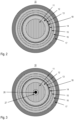
- FIG 2 a cross-section through the vacuum feedthrough 10 is shown.
- the sequence of materials from the inside to the outside is: sapphire (vertically hatched), glass (diagonally crossed hatched), sapphire, platinum (black), glass, ceramic (horizontally hatched), glass, metal (diagonally hatched).
- the first electrically conductive layer 18 is electrically insulated from the metallic frame 17.
- the Elements of the shell-shaped feedthrough are each connected to the adjacent elements in a vacuum-tight manner.
- FIG 3 a cross section through an embodiment of the vacuum feedthrough 10 is shown, which has an additional central electrode 26 through the lens element.
- the additional electrode is glazed into the lens element by means of an additional ring 27.
- the additional electrode can be designed in the form of a rod or wire and protrude beyond the feedthrough on both sides, ie the vacuum side and the atmosphere side.
- FIG 4 a cross section through an embodiment of the vacuum feedthrough 10 is shown, which has further electrodes 28, 29 arranged radially in the area of the second ring 16 made of glass.
- Two further electrodes are shown here as an example, but a plurality of such electrodes in the form of azimuthally spaced strips with a longitudinal direction parallel to the axis of the hollow cylinders can be arranged on this radius.
- One of these further electrodes can, for example, be the central electrode 26 from the embodiment according to Fig. 3
- the central electrode can be made of Fig. 3 also with additional electrodes arranged radially further outwards according to Fig.
- the other electrodes 28, 29 can be applied, for example, as thin metallizations on the hollow cylinder 15 made of ceramic and through the The second ring 16 made of glass must be vacuum-tightly coated on the side facing away from the ceramic cylinder.
- Various metals can be used as the material for the other electrodes, in particular platinum, molybdenum and titanium.
- the other electrodes can be used to electrically contact other plasma chambers and/or sensors on the vacuum side, for example a cold cathode vacuum manometer or a Pirani pressure sensor. In order to enable electrical contact to such other electrodes on the outside, for example and deviating from the illustration in Fig.
- the ceramic cylinder 15 also protrudes beyond the ring 16 on the side of the vacuum feedthrough facing away from the vacuum side, thus forming a support surface for the additional electrodes on this side as well and enabling electrical contact on the radially outer side.
- additional electrodes can, for example, be covered over their entire length with an insulating layer. This has the advantage that in electron/ion optics, often undesirable exposed potentials that could influence charged particles are avoided.
- a glass ring lying over the electrodes can be extended further axially or individual conductor tracks can be implemented with a thin glass layer that overlaps the respective conductor track.
- the present invention enables pressure measurement or gas analysis in the range 0.047 - 199.98 kPa (0.35 - 1500 Torr), i.e. up to the overpressure range, for example by means of a cylindrical sapphire high-voltage feedthrough with an integrated lens system.
- a DBD plasma can be ignited by applying an alternating voltage in the range 1-10 kilovolts and with a frequency in the range 1-10 kilohertz.
- the invention enables a small, energy-efficient and flexible gas analysis device with high sensitivity and for a wide variety of applications.
Landscapes
- Physics & Mathematics (AREA)
- Engineering & Computer Science (AREA)
- Plasma & Fusion (AREA)
- General Physics & Mathematics (AREA)
- Analytical Chemistry (AREA)
- Chemical & Material Sciences (AREA)
- Health & Medical Sciences (AREA)
- Spectroscopy & Molecular Physics (AREA)
- General Health & Medical Sciences (AREA)
- Immunology (AREA)
- Pathology (AREA)
- Life Sciences & Earth Sciences (AREA)
- Nuclear Medicine, Radiotherapy & Molecular Imaging (AREA)
- Biochemistry (AREA)
- Measuring Fluid Pressure (AREA)
- Plasma Technology (AREA)
- Photometry And Measurement Of Optical Pulse Characteristics (AREA)
Description
- Die vorliegende Erfindung betrifft eine Vakuumdurchführung, eine Elektrodenanordnung und eine Vorrichtung zur Erzeugung einer stillen Plasmaentladung. Weiter betrifft die Erfindung ein Messgerät zur Charakterisierung einer Druck- und/oder Gaszusammensetzung und ein Verfahren zum Betrieb des Messgeräts.
- Die vorliegende Erfindung gehört zum technischen Gebiet der Plasmaerzeugung, dem Ionisieren und Anregen von Molekülen und Ionen, um Plasmalicht zu erzeugen, und weiter, der Messung und Auswertung von Informationen über die Gaszusammensetzung des erzeugten Plasmas. Eine mögliche Art der Plasmaentladung ist die sogenannte DBD-Plasmaentladung. Eine DBD-Plasmaentladung (auch stille elektrische Entladung oder auch dielektrische Barriereentladung genannt, englisch "dielectric barrier discharge", abgekürzt DBD) ist eine Wechselspannungs-Gasentladung, bei der mindestens eine der Elektroden vom Gasraum durch galvanische Trennung mittels eines Dielektrikums elektrisch isoliert ist. Man spricht auch von dielektrisch behinderter Entladung, da durch die Isolierung das Entstehen einer Bogenentladung verhindert wird.
- Die Messung und Auswertung des in einem DBD-Plasma erzeugten Lichts ist mit vielerlei Schwierigkeiten verbunden. Lebensdauer und gegebenenfalls Vakuumtauglichkeit von Elementen, Grösse und Komplexität von Aufbauten sowie die erreichbare Empfindlichkeit sind stellen grosse Herausforderungen dar.
- Die in
WO 2021/052600 A1 beschriebene vakuumdichte elektrische Durchführung umfasst ein elektrisch isolierendes Isolator-Element mit einer Durchgangsöffnung, mit einer an die Durchgangsöffnung angrenzenden ersten Begrenzungsfläche und mit einer ebenfalls an die Durchgangsöffnung angrenzenden, der ersten Begrenzungsfläche gegenüberliegenden zweiten Begrenzungsfläche. Die vakuumdichte elektrische Durchführung umfasst weiter ein elektrisch leitendes Leiter-Element, welches sich durch die Durchgangsöffnung hindurch erstreckt und welches entlang einer Umfangslinie des Leiter-Elements vakuumdicht mit dem Isolator-Element verbunden ist. Das Isolator-Element ist für elektromagnetische Strahlung in einem optischen Wellenlängenbereich durchlässig. Die erste und/oder die zweite Begrenzungsfläche ist als gekrümmte Fläche ausgebildet. Die gekrümmte Fläche kann insbesondere als konvexe oder konkave Fläche ausgebildet sein. - Die Aufgabe der vorliegenden Erfindung bestand darin, zumindest eines der Probleme des Stands der Technik zu vermindern. Namentlich ist ein Ziel der Erfindung, einen kompakten Sensor für Druck und/oder Gaszusammensetzung basierend auf einer DBD-Plasmaentladung zu ermöglichen und dazu geeignete Komponenten zur Verfügung zu stellen. Diese Aufgabe wird erfindungsgemäss durch eine Vakuumdurchführung nach Anspruch 1 gelöst. Ausführungsformen ergeben sich aus den Merkmalen der abhängigen Ansprüche 2 bis 4.
- Die Vakuumdurchführung umfasst die Elemente
- Linsenelement,
- erster Ring aus Glas,
- erster Hohlzylinder aus einem ersten dielektrischen Material,
- erste elektrisch leitende Schicht,
- zweiter Hohlzylinder aus Glas,
- dritter Hohlzylinder aus Keramik,
- zweiter Ring aus Glas,
- Rahmen aus Metall,
- Der Rahmen kann insbesondere ringförmig sein. Der Rahmen kann insbesondere aus Edelstahl sein.
- Es existiert zumindest ein durchgehender Strahlungspfad für eine Strahlung aus einem optischen Wellenlängenbereich ausgehend von einem ersten Punkt auf einer ersten Seite, durch das Linsenelement hindurch zu einem zweiten Punkt auf einer zweiten Seite der Vakuumdurchführung.
- Das Linsenelement ist transparent für mindestens einen Wellenlängenbereich im optischen Wellenlängenbereich und stellt damit den optischen Teil der Vakuumdurchführung dar. Soweit die Elemente der Vakuumdurchführung nicht transparent sind im besagten Wellenlängenbereich lassen sie den Durchgang entlang dem mindestens einen durchgehenden Strahlungspfad unversperrt. Der optische Wellenlängenbereich umfasst elektromagnetische Strahlung mit Wellenlängen von 100 nm bis 1 mm, also insbesondere die Bereiche des sichtbaren Lichts, der UV-Strahlung und der Infrarot-Strahlung. Das Linsenelement kann beispielsweise die Form einer plan-konvexen Linse haben, wobei die konvexe Seite in Richtung der ersten Seite der Dichteben gerichtet ist. Das Linsenelement kann beispielsweise eine Pilzkopfartige Durchmesservergrösserung auf der ersten Seite aufweisen, sodass ein radialer Überlapp mit dem ersten Ring entsteht. Auf diese Weise kann von der ersten Seite her eintreffende Strahlung gebündelt werden. Beispielsweise kann das Linsenelement durch die Kombination von Linsenradien und Brechungsindex dazu ausgelegt sein, von der ersten Seite her eintreffende parallele Strahlungspfade auf der zweiten Seite in einem Brennpunkt, oder zumindest in einem Brennvolumen, zu konzentrieren.
- Die erste Seite kann insbesondere als Vakuumseite und die zweite Seite kann insbesondere als Atmosphärenseite vorgesehen sein. Der Begriff Vakuumdurchführung soll im Zusammenhang mit vorliegender Erfindung so verstanden werden, dass die Durchführung dafür geeignet ist, in einer Situation mit einer erheblichen Druckdifferenz zwischen der ersten und der zweiten Seite eingesetzt zu werden, ohne dass ein Gas durch die Dichtfläche hindurch auf die andere Seite gelangt. Diese Anforderung ist typisch für die Verwendung einer Durchführung in der Vakuumtechnik, kann aber auch in anderen Anwendungen von Nutzen sein, in denen auf keiner Seite ein Druck im Vakuumbereich herrscht.
- Die erfindungsgemässe Vakuumdurchführung ist also eine elektrisch-optische Vakuumdurchführung. Die erste elektrisch leitende Schicht bildet isoliert vom Rahmen die elektrische Durchführung. Das Linsenelement bildet die optische Durchführung.
- Optional kann auf einer zentralen Achse des Linsenelements zusätzlich eine Stab- oder Drahtförmige Elektrode durch das Linsenelement hindurchgeführt werden, wobei diese weitere Elektrode mittels eines weiteren Rings aus Glas eingeglast sein kann. Eine solche weitere Elektrode kann im Fall, dass eine Spannungsversorgung weiterer Elemente erforderlich ist, den gesamten Aufbau kompakt halten.
- In einer Ausführungsform der erfindungsgemässen Vakuumdurchführung sind die aneinandergrenzenden Elemente (Elemente sind das Linsenelement und die weiteren Elemente aus der obigen Liste) vakuumdicht miteinander verbunden zur Ausbildung einer Dichtfläche, welche eine erste Seite, insbesondere eine Vakuumseite, und eine zweite Seite, insbesondere eine Atmosphärenseite, der Vakuumdurchführung voneinander trennt.
- Auf der Aussenfläche des ersten Hohlzylinders ist die erste elektrisch leitende Schicht aufgebracht. Diese elektrisch leitende Schicht kann aus einem Metall, insbesondere aus Platin sein.
- Der erste Hohlzylinder und die erste elektrisch leitende Schicht ragen auf der Atmosphärenseite über den zweiten Hohlzylinder hinausragen zur Ausbildung einer elektrischen leitenden Kontaktfläche. An der Kontaktfläche kann die erste Elektrode z.B. mit einer Hochspannungsquelle verbunden werden, sodass die erste elektrisch leitende Schicht als eine Elektrode für die DBD-Plasmaentladung dienen kann. Die erste elektrisch leitende Schicht kann die Form eines Hohlzylinders haben. Die erste elektrisch leitende Schicht kann segmentiert sein, d.h. beispielsweise im Bereich, in dem Sie als Elektrode für die DBD-Entladung dient und/oder im Bereich der Durchführung unter dem Glasring als nebeneinander liegende Längsstreifen ausgebildet sein.
- Der erste, der zweite und der dritte Hohlzylinder, sowie die erste elektrisch leitende Schicht ragen auf der ersten Seite über das Linsenelement hinaus.
- Die Elemente bilden jeweils eine im Wesentlichen ringförmige Zone der Dichtfläche aus. Der erste Ring aus Glas grenzt radial ausserhalb an das Linsenelement an und ist mit dem Linsenelement vakuumdicht verbunden. Der erste Hohlzylinder grenzt radial ausserhalb an den ersten Ring an und ist mit diesem vakuumdicht verbunden, usw. In dieser Anordnung hat jede Schicht zumindest eine benachbarte Schicht aus Glas. Der erste und der zweite Ring aus Glas, sowie der zweite Hohlzylinder, können insbesondere aus Schmelzglas bestehen. Das Schmelzglas kann insbesondere ein sogenanntes Lotglas sein, welches sich besonders gut zur Herstellung einer vakuumdichten Verbindung zu einem Metall oder einer Keramik eignet. Der metallische Rahmen kann in Form eines Rings ausgebildet sein. Der metallische Rahmen kann beispielsweise einen Flansch aufweisen, welcher so ausgestaltet ist, dass er ein Verschweissen des Rahmens mit weiteren Elementen erleichtert. Der metallische Rahmen kann beispielsweise aus einem nichtrostenden austenitischen Stahl bestehen, beispielsweise aus Stahl 1.4435 oder aus Stahl 1.4404, welcher sich durch eine hohe Korrosionsbeständigkeit auszeichnet.
- Die Elemente können je einzeln die Form eines Rotationskörpers mit einer Rotationsachse haben. Die Elemente können bezüglich ihrer Rotationsachsen koaxial zueinander angeordnet sein.
- Auf der ersten Seite, d.h. beispielsweise vakuumseitig, kann die elektrisch leitende Schicht komplett zwischen dem ersten und zweiten Hohlzylinder eingeschlossen sein. In diesem Fall ist vakuumseitig nur eine kapazitive Ankopplung an die Elektrode möglich. Ein komplettes Einschliessen der elektrisch leitenden Schicht in isolierendes Material hat den Vorteil, dass das Entstehen einer Bogenentladung verhindert werden kann.
- Der dritte Hohlzylinder aus Keramik hat die Wirkung, einen elektrischen Durchschlag durch den zweiten Hohlzylinder aus Glas zu unterdrücken, für den Fall, dass das Glas nicht ausreichend durchschlagsresistent ist. Beispielsweise wird eine Entladung zwischen einem Metallgehäuse-Rohr eines im Folgenden noch zu besprechenden Messgeräts durch den dritten Hohlzylinder aus Keramik erfolgreich verhindert. Der dritte Hohlzylinder kann insbesondere aus einer Al2O3-Keramik bestehen.
- In einer Ausführungsform der Vakuumdurchführung besteht das Linsenelement aus Saphir.
- Saphir hat einen hohen Transmissionsgrad im Wellenlängenbereich 200 nm bis 5000 nm und damit besonders geeignet, um elektromagnetische Strahlung aus dem optischen Bereich mit geringem Verlust aus einem Vakuumbereich hinauszuführen. Insbesondere ist die Transmission im Ultraviolett-Bereich oberhalb von 200 nm hoch. Ausserdem ist Saphir mechanisch sehr robust.
- In einer Ausführungsform der Vakuumdurchführung besteht der erste Hohlzylinder aus Saphir.
- Weiter ist die Erfindung auf eine Elektrodenanordnung nach Anspruch 5 gerichtet. Eine Ausführungsform der Elektrodenanordnung ergibt sich aus den Merkmalen des Anspruchs 6.
- Die erfindungsgemässe Elektrodenanordnung ist eine Elektrodenanordnung zur Erzeugung einer DBD-Plasmaentladung. Die Elektrodenanordnung umfasst die oben besprochene erfindungsgemässe Vakuumdurchführung. Sie umfasst weiter einen vierten Hohlzylinder aus Keramik, welcher auf seiner Aussenfläche eine zweite, elektrisch leitende Schicht trägt. Die zweite elektrisch leitende Schicht kann insbesondere aus Molybdän sein.
- Der vierte Hohlzylinder ist auf der ersten Seite (der Vakuumseite) der Vakuumdurchführung koaxial zum ersten Hohlzylinder angeordnet. Er liegt zumindest teilweise innerhalb des ersten Hohlzylinders. Die erste und die zweite elektrisch leitende Schicht überlappen in axialer Richtung teilweise.
- Zwischen der zweiten elektrisch leitenden Schicht und der Innenfläche des ersten Hohlzylinders bleibt ein Spalt mit einer radialen Ausdehnung offen.
- Die erste und die zweite elektrisch leitende Schicht bilden die beiden Elektroden der Elektrodenanordnung. Im Betrieb bildet sich im besagten Spalt eine Plasmaentladungszone aus, und zwar in axialer Richtung in dem Bereich, in dem die beiden Elektroden überlappen.
- Der vierte Hohlzylinder hat den Effekt eines Sputterschutzes. Er erhöht die Lebensdauer der Elektrodenanordnung. Der vierte Hohlzylinder kann beispielsweise aus einer Al2O3-Keramik bestehen. Eine weitere Massnahme, welche einen Sputterschutz bewirkt, ist die Dimensionswahl der Durchführung. Ein grosser Abstand zwischen Linsenelement zur Region der Plasmaentladung reduziert den Sputtereffekt auf das Linsenelement.
- Insbesondere ein grosser Abstand in Relation zum Durchmesser des Linsenelements ist hierzu wirksam.
- In einer Ausführungsform der Elektrodenanordnung beträgt die radiale Ausdehnung des Spalts weniger als 1 mm. Die radiale Ausdehnung des Spalts kann insbesondere zwischen 0.05 mm und 0.5 mm betragen. Die Erfinder haben erkannt, dass sich mit dieser Ausdehnung des Spalts die DBD-Plasmaentladung mit einer hochfrequenten Spannung im Kilovolt-Bereich (1 - 10 kV, 1 - 10 kHz) über einen grossen Druckbereich zünden lässt. Der Betrieb in einem Druckbereich von ca. 0.047 - 199.98 kPa (0.35 - 1500 Torr) ist möglich.
- Ausserdem betrifft die Erfindung eine Vorrichtung nach Anspruch 7.
- Die erfindungsgemässe Vorrichtung ist eine Vorrichtung zur Erzeugung einer DBD-Plasmaentladung. Die Vorrichtung umfasst die oben besprochene, erfindungsgemässe Elektrodenanordnung. Der Spalt zwischen der zweiten elektrisch leitenden Schicht und der Innenfläche des ersten Hohlzylinders steht in fluiddynamischer Verbindung mit dem Innern der Vakuumkammer.
- Die erste elektrisch leitende Schicht ist an der elektrischen leitenden Kontaktfläche mit einer Wechselspannungs-Hochspannungsquelle elektrisch leitend verbunden ist und die zweite elektrisch leitende Schicht ist elektrisch leitend mit Masse verbunden.
- Die Elektrodenanordnung kann beispielsweise in eine metallische Wandung einer Vakuumkammer eingebaut sein, wobei der Rahmen an seinem Umfang mit der Wandung der Vakuumkammer vakuumdicht verschweisst ist. Durch den grossen Druckbereich in welchem mit der erfindungsgemässen Vorrichtung eine DBD-Entladung möglich ist, kann ein Betrieb der Vorrichtung beispielsweise auch in Umgebungsdruck, d.h. ohne eine Kammer, welche die erste von der zweiten Seite fluiddynamisch trennt, stattfinden.
- Noch weiter ist die Erfindung auf ein Messgerät nach Anspruch 8 gerichtet.
- Das erfindungsgemässe Messgerät ist ein Messgerät zur Charakterisierung eines Drucks und/oder einer Gaszusammensetzung. Das Messgerät umfasst die oben besprochene erfindungsgemässe Vorrichtung zur Erzeugung einer DBD-Plasmaentladung. Zusätzlich ist auf der Atmosphärenseite des Linsenelements ein optischer Sensor angeordnet.
- Der optische Sensor ist in dem Wellenlängenbereich empfindlich, welche durch das Linsenelement transmittiert werden kann. Der optische Sensor kann ein einfacher Strahlungssensor, z.B. ein Lichtsensor sein, es kann sich aber auch um einen komplexeren optischen Sensor handeln, z.B. ein Spektrometer. Eine Photodiode mit einem wellenlängenselektiven Filter kann beispielsweise als optischer Sensor dienen.
- Das erfindungsgemässe Messgerät eignet sich beispielsweise zur Charakterisierung einer Druck- und/oder Gaszusammensetzung innerhalb einer Vakuumkammer. Die optimale Verwendung der Erfindung liegt im Druckbereich von 0.35-1500 Torr (-2000 mbar), also auch im Druckbereich bei und über Atmosphärendruck und ist daher breit einsetzbar. Die spezifische Wahl der verwendeten Materialien kann gemäss den oben erwähnten Ausführungsformen spezifisch auf Vakuumanforderungen angepasst werden. Namentlich die Verwendung von Saphir als Dielektrikum, von Platin und Molybdän als Elektrodenmaterial und von Edelstahl für den Rahmen tragen zur Vakuumtauglichkeit des Messgeräts bei. Weiter sind die genannten Materialien mit den typischen Anforderungen einer Vakuum-Prozess-Anlage der HalbleiterIndustrie verträglich.
- Weiter ist die Erfindung auf ein Verfahren nach Anspruch 9 gerichtet. Es handelt sich dabei um ein Verfahren zum Betrieb eines erfindungsgemässen Messgeräts. Im erfindungsgemässen Verfahren wird zwischen der ersten elektrisch leitenden Schicht und der zweiten elektrisch leitenden Schicht eine Wechselspannung mit einer Spannungsamplitude von 1 bis 10 Kilovolt und einer Frequenz im Bereich 1 bis 10 Kilohertz angelegt. Beispielsweise kann der Spannungsverlauf über eine Periode der Wechselspannung von -5 kV zu +5kV und wieder zurück wechseln, d.h. eine Spannung von 10 kVpp angelegt werden. Der Spannungsverlauf kann beispielsweise einem Sinus-Verlauf entsprechen. Eine Rechteck-Spannung ist ebenfalls möglich. Vorteilhaft ist es, die Spannung von positiv zu negativ gegenüber Massepotential zu variieren. Auf diese Weise erhält man ein deutlich stabileres Plasma als beispielsweise durch eine Variation zwischen 0 und positiver Spannung oder zwischen 0 und negativer Spannung.
- Durch das Anlegen der Spannung wird im Spalt zwischen zweiter elektrisch leitender Schicht und dem Dielektrikum im Bereich des axialen Überlappungsbereich der beiden elektrisch leitenden Schichten ein Plasma gezündet, welches aufgrund der Ladungsansammlung auf dem Dielektrikum nur eine kurze Lebensdauer hat. Durch den Wechsel des Vorzeichens der angelegten Wechselspannung werden die angesammelten Ladungsträger wieder vom Dielektrikum wegbewegt, sodass ein kontinuierlich scheinendes Plasma aufrechterhalten werden kann. Die vom Plasma emittierte Strahlung wird im optischen Sensor detektiert.
- Ausführungsbeispiele der vorliegenden Erfindung werden nachstehend anhand von Figuren noch näher erläutert. Es zeigen
-
Fig. 1 schematisch und teilweise als Querschnitt eine erfindungsgemässe Vakuumdurchführung im Zusammenhang mit einer Ausführungsform der Elektrodenanordnung, einer Ausführungsform der Vorrichtung und einer Ausführungsform des Messgeräts; -
Fig. 2 einen Querschnitt durch die erfindungsgemässe Vakuumdurchführung entlang der Dichtfläche; -
Fig. 3 einen Querschnitt durch eine Ausführungsform der Vakuumdurchführung entlang der Dichtfläche; -
Fig. 4 einen Querschnitt durch eine weitere Ausführungsform der Vakuumdurchführung entlang der Dichtfläche. - In
Figur 1 ist in einem Längsschnitt das zentrale Element der Erfindung, nämlich die Vakuumdurchführung, gezeigt. Die in radialen Lagen aufgebaute elektro-optische Vakuumdurchführung 10 umfasst ein zentral angeordnetes Linsenelement 11 und um das Linsenelement herum angeordnet folgende weitere Elemente, in radialer Richtung von innen nach aussen aufgezählt: - ein erster Ring 12 aus Glas,
- ein erster Hohlzylinder 13 aus einem ersten dielektrischen Material,
- ein zweiter Hohlzylinder 14 aus Glas,
- ein dritter Hohlzylinder 15 aus Keramik,
- ein zweiter Ring 16 aus Glas,
- ein Rahmen 17 aus Metall.
- Weiter ist auf der Aussenfläche des ersten Hohlzylinders eine erste elektrisch leitende Schicht 18 aufgebracht, welche insbesondere aus Platin sein kann.
- Eine Dichtfläche 1 trennt eine erste Seite 2, in diesem Fall die Vakuumseite, welche ins Innere der Vakuumkammer 31 zu liegen kommt, von einer zweiten Seite 3, welche in diesem Fall die Atmosphärenseite ist. Im gezeigten Längsschnitt ist die Dichtfläche 1 entlang einer Linie geschnitten, welche als gestrichelte Linie dargestellt ist. Auf der Atmosphärenseite einer Vakuumkammer 31 sind ein optischer Sensor 41 und eine Hochspannungsquelle 32 untergebracht. Ein vierter Hohlzylinder 21 und die auf dessen Aussenfläche angebrachte zweite elektrisch leitende Schicht 22 ergänzen die Vakuumdurchführung zu einer Elektrodenanordnung 20. In der gezeigten Ausführungsform haben die Elemente der Elektrodenanordnung alle die Form von Rotationskörpern mit der gemeinsamen Rotationsachse 4 (strichpunktierte Linie).
- Eine erste elektrisch leitende Schicht 18 ist an einer Kontaktfläche 19 an die Hochspannungsquelle 32 angeschlossen. Die zweite elektrisch leitende Schicht ist mit Masse verbunden, sodass erste und zweite elektrisch leitende Schicht die beiden Elektroden der Elektrodenanordnung bilden. Die beiden Elektroden überlappen in einem axialen Überlappungsbereich 23. In diesem Überlappungsbereich und radial zwischen der zweiten elektrisch leitenden Schicht 22 und dem Hohlzylinder 13, welcher insbesondere aus Saphir sein kann, bildet sich im Betrieb ein Entladungsbereich 25 aus (gepunktet dargestellt). Aus diesem Entladungsbereich heraus wird elektromagnetische Strahlung, z.B. aus dem sichtbaren Bereich, dem UV-Bereich oder dem IR-Bereich, emittiert. Diese Strahlung kann insbesondere in Richtung auf das Linsenelement in abgestrahlt werden (durch wellenförmige Pfeile dargestellt). Es ist diese Strahlung, welche durch das Linsenelement 11 hindurch zum optischen Sensor 41 gelangt, wo sie detektiert wird.
- Die erste 18 und zweite 22 elektrisch leitende Schicht können in axialer Richtung beispielsweise 2-3 mm überlappen. Der vierte Hohlzylinder 21 kann beispielsweise ca. 5 mm über die zweite elektrisch leitende Schicht 22 hinaus vorstehen in Richtung auf das Linsenelement zu. Der kürzeste Abstand von der zweiten elektrischen Schicht 22 zum Linsenelement 11 kann beispielsweise ca. 10 mm betragen. Diese Dimensionen passen zu einem Entladungsbereich mit einer radialen Ausdehnung von 0.05 bis 0.5 mm, gemäss einer oben beschriebenen Ausführungsform. Mit den genannten Abstandsverhältnissen entsteht die schon oben erwähnte Sputterschutz-Wirkung. Durch die Entladung aus dem Elektrodenmaterial herausgeschlagene Teilchen werden in dieser Anordnung mit einer hohen Wahrscheinlichkeit an der vorstehenden Keramikfläche des vierten Hohlzylinders hängen bleiben und damit nicht das Linsenelement verschmutzen. Strahlung aus dem Entladungsbereich 25 kann in etwa parallel zur Achsenrichtung zum Linsenelement gelangen, auch wenn der vierte Hohlzylinder selbst nicht transparent ist für die Strahlung oder bereits durch Elektrodenmaterial verschmutzt ist.
- Gezeigt ist eine Ausführungsform Messgerät resp. Vorrichtung, bei welcher die Elektrodenanordnung in eine metallische Wandung einer Vakuumkammer 31 eingebaut ist, wobei der Rahmen an seinem Umfang mit der Wandung der Vakuumkammer vakuumdicht verschweisst ist.
- Insbesondere die Vakuumkammer 31 und der Wandung, sowie Hochspannungsquelle 32 und optischer Sensor 41 sind sehr schematisch dargestellt und bezüglich Dimensionen nicht an die Dimensionen der Elektrodenanordnung angepasst. Insbesondere die Vakuumkammer kann in Relation zur Vakuumdurchführung um ein Vielfaches grösser sein als dargestellt. Ebenfalls schematisch und unvollständig dargestellt ist das vom Linsenelement weiter entfernte Ende des vierten Hohlzylinders und der zweiten elektrisch leitenden Schicht. Die axialen Enden dieser beiden Elemente sind zueinander versetzt dargestellt, sodass die beiden Lagen deutlich erkennbar sind. Die beiden Elemente können sich in axialer Richtung aber weiter erstrecken als gezeigt und die zweite elektrische leitende Schicht kann insbesondere über ihre ganze Länge auf dem vierten Hohlzylinder aufliegen. Eine nicht gezeigte mechanische Befestigungsvorrichtung hält den vierten Hohlzylinder in seiner Position.
- In
Figur 2 ist ein Querschnitt durch die Vakuumdurchführung 10 gezeigt. In einer bevorzugten Ausführungsform ist die Abfolge der Materialien von innen nach aussen: Saphir (senkrecht schraffiert), Glas (diagonal gekreuzt schraffiert), Saphir, Platin (schwarz), Glas, Keramik (horizontal schraffiert), Glas, Metall (diagonal schraffiert). Die erste elektrisch leitende Schicht 18 ist elektrisch vom metallischen Rahmen 17 isoliert. Die Elemente der schalenförmig aufgebauten Durchführung sind mit den angrenzenden Elementen jeweils vakuumdicht verbunden. - In
Figur 3 ist ein Querschnitt durch eine Ausführungsform der Vakuumdurchführung 10 gezeigt, welche eine zusätzliche zentrale Elektrode 26 durch das Linsenelement hindurch aufweist. Die zusätzliche Elektrode ist mittels eines zusätzlichen Rings 27 ins Linsenelement eingeglast. Die zusätzliche Elektrode kann Stab- oder Drahtförmig ausgebildet sein und beidseitig, d.h. vakuumseitig und atmosphärenseitig über die Durchführung hinausragen. - In
Figur 4 ist ein Querschnitt durch eine Ausführungsform der Vakuumdurchführung 10 gezeigt, welche weitere, radial im Bereich des zweiten Rings 16 aus Glas angeordnete Elektroden 28, 29 aufweist. Beispielhaft sind hier zwei weitere Elektroden gezeigt, es können aber eine Mehrzahl derartige Elektroden in Form von azimutal voneinander beabstandeten Streifen mit einer Längsrichtung parallel zur Achse der Hohlzylinder auf diesem Radius angeordnet sein. Eine dieser weiteren Elektroden kann beispielsweise die zentrale Elektrode 26 aus dem Ausführungsbeispiel gemässFig. 3 ersetzen. In einer weiteren Ausführungsform kann die zentrale Elektrode ausFig. 3 auch mit weiteren radial weiter aussen angeordneten Elektroden gemässFig. 4 kombiniert werden. Die weiteren Elektroden 28, 29 können beispielsweise als dünne Metallisierungen auf den Hohlzylinder 15 aus Keramik aufgebracht sein und durch den zweiten Ring 16 aus Glas auf der vom Keramikzylinder abgewandten Seite vakuumdicht ummantelt sein. Als Material für die weiteren Elektroden kommen verschiedene Metalle in Frage, insbesondere Platin, Molybdän und Titan. Über die weiteren Elektroden können beispielsweise weitere Plasmakammern und/oder Sensoren auf der Vakuumseite elektrisch kontaktiert werden, beispielsweise ein Kaltkathoden-Vakuummanometer oder ein Pirani-Drucksensor. Um auf der Aussenseite einen elektrischen Kontakt auf derartige weitere Elektroden zu ermöglichen, kann beispielsweise und abweichend von der Darstellung inFig. 1 , der Keramikzylinder 15 auch auf der von der Vakuumseite abgewandten Seite der Vakuumdurchführung über den Ring 16 hinausragen und so auch auf dieser Seite eine Auflagefläche für die weiteren Elektroden zu bilden und auf der radial äusseren Seite eine elektrische Kontaktierung zu ermöglichen. Solche weiteren Elektroden können beispielsweisen über ihre komplette Länge mit einer Isolierschicht abgedeckt sein. Dies hat den Vorteil, dass in der Elektronen-/Ionenoptik oftmals unerwünschte offenliegende Potentiale, welche geladene Teilchen beeinflussten könnten, vermieden werden. Dazu kann beispielsweise ein über den Elektroden liegender Glasring weiter axial ausgedehnt werden oder einzelnen Leiterbahnen können mit einer dünnen Glasschicht, welche überlappend über der jeweiligen Leiterbahn liegt, verwirklicht sein. - Zusammenfassend ermöglicht die vorliegende Erfindung eine Druckmessung oder eine Gasanalyse im Bereich
0.047 - 199.98 kPa (0.35 - 1500 Torr), also bis in den Überdruckbereich, beispielsweise mittels einer zylinderförmigen Saphir-Hochspannungsdurchführung mit integriertem Linsensystem. Ein DBD-Plasma kann durch Anlegen einer Wechselspannung im Bereich 1-10 Kilovolt und mit einer Frequenz im Bereich 1-10 Kilohertz gezündet werden. Die Erfindung ermöglicht ein kleines, energieeffizientes und flexibel einsetzbares Gasanalysegerät mit hoher Sensitivität und für verschiedenste Anwendungen. -
- 1
- Dichtfläche
- 2
- erste Seite (Vakuumseite)
- 3
- zweite Seite (Atmosphärenseite)
- 4
- gemeinsame Achse
- 10
- Vakuumdurchführung
- 11
- Linsenelement
- 12
- erster Ring (Glas)
- 13
- erster Hohlzylinder (erstes dielektrisches Material)
- 14
- zweiter Hohlzylinder (Glas)
- 15
- dritter Hohlzylinder (Keramik)
- 16
- zweiter Ring (Glas)
- 17
- Rahmen (Metall)
- 18
- erste elektrisch leitende Schicht
- 19
- Kontaktfläche
- 20
- Elektrodenanordnung
- 21
- vierter Hohlzylinder (Keramik)
- 22
- zweite elektrische leitende Schicht
- 23
- axialer Überlappbereich
- 24
- Spalt
- 25
- Entladungszone im Spalt
- 26
- zusätzliche (zentrale) Elektrode
- 27
- zusätzlicher Ring (Glas)
- 28, 29
- weitere Elektroden
- 30
- Vorrichtung
- 31
- Vakuumkammer
- 32
- Wechselspannungs-Hochspannungsquelle
- 40
- Messgerät
- 41
- optischer Sensor
Claims (9)
- Vakuumdurchführung (10), umfassend die Elemente- Linsenelement (11),- erster Ring (12) aus Glas,- erster Hohlzylinder (13) aus einem ersten dielektrischen Material,- erste elektrisch leitende Schicht (18),- zweiter Hohlzylinder (14) aus Glas,- dritter Hohlzylinder (15) aus Keramik,- zweiter Ring aus Glas (16),- Rahmen (17) aus Metall,in der genannten Abfolge radial von innen nach aussen, wobei zumindest ein durchgehender Strahlungspfad existiert für eine Strahlung aus einem optischen Wellenlängenbereich ausgehend von einem ersten Punkt auf einer ersten Seite (2) der Vakuumdurchführung, durch das Linsenelement hindurch zu einem zweiten Punkt auf einer zweiten Seite (3) der Vakuumdurchführung.
- Vakuumdurchführung (10) nach Anspruch 1,wobei aneinandergrenzende Elemente (11,12,13,14,15,16,17) vakuumdicht miteinander verbunden sind zur Ausbildung einer Dichtfläche (1), welche die erste Seite (2) und die zweite Seite (3) der Vakuumdurchführung voneinander trennt,wobei auf der Aussenfläche des ersten Hohlzylinders eine erste elektrisch leitende Schicht (18), insbesondere aus Platin, aufgebracht ist,wobei der erste Hohlzylinder und die erste elektrisch leitende Schicht auf der zweiten Seite über den zweiten Hohlzylinder hinausragen zur Ausbildung einer elektrischen leitenden Kontaktfläche (19),wobei der erste, zweite und dritte Hohlzylinder, sowie die erste elektrisch leitende Schicht auf der ersten Seite über das Linsenelement hinausragen.
- Vakuumdurchführung (10) nach Anspruch 1 oder 2, wobei das Linsenelement (11) aus Saphir besteht.
- Vakuumdurchführung (10) nach einem der Ansprüche 1 bis 3, wobei der erste Hohlzylinder (13) aus Saphir besteht.
- Elektrodenanordnung (20) zur Erzeugung einer DBD-Plasmaentladung, wobei die Elektrodenanordnung die Vakuumdurchführung (10) nach einem der Ansprüche 1 bis 4 umfasst und weiter einen vierten Hohlzylinder (21) aus Keramik umfasst, welcher auf seiner Aussenfläche eine zweite elektrisch leitende Schicht (22), insbesondere aus Molybdän, trägt,wobei der vierte Hohlzylinder (21) auf der ersten Seite (2) der Vakuumdurchführung koaxial zum ersten Hohlzylinder (13) angeordnet ist und zumindest teilweise innerhalb des ersten Hohlzylinders liegt,wobei die erste und die zweite elektrisch leitende Schicht in axialer Richtung teilweise überlappen,und wobei zwischen der zweiten elektrisch leitenden Schicht und der Innenfläche des ersten Hohlzylinders ein Spalt (24) mit einer radialen Ausdehnung offen bleibt.
- Elektrodenanordnung (20) nach Anspruch 5, wobei die radiale Ausdehnung des Spalts (24) weniger als 1 mm beträgt, insbesondere wobei die radiale Ausdehnung des Spalts zwischen 0.05 mm und 0.5 mm beträgt.
- Vorrichtung (30) zur Erzeugung einer DBD-Plasmaentladung, wobei die Vorrichtung die Elektrodenanordnung (20) gemäss Anspruch einem der Ansprüche 5 oder 6 umfasst,wobei der Spalt zwischen der zweiten elektrisch leitenden Schicht und der Innenfläche des ersten Hohlzylinders in fluiddynamischer Verbindung mit dem Innern der Vakuumkammer steht,wobei die erste elektrisch leitende Schicht an der elektrischen leitenden Kontaktfläche mit einer Wechselspannungs-Hochspannungsquelle (32) elektrisch leitend verbunden ist, und wobei die zweite elektrisch leitende Schicht elektrisch leitend mit Masse verbunden ist.
- Messgerät (40) zur Charakterisierung eines Drucks und/oder einer Gaszusammensetzung, wobei das Messgerät die Vorrichtung nach Anspruch 7 umfasst und wobei auf der Atmosphärenseite (3) des Linsenelements (11) ein optischer Sensor (41) angeordnet ist.
- Verfahren zum Betrieb eines Messgeräts (40) nach Anspruch 8, wobei zwischen der ersten elektrisch leitenden Schicht (18) und der zweiten elektrisch leitenden Schicht (22) eine Wechselspannung mit einer Spannungsamplitude von 1 bis 10 Kilovolt und einer Frequenz im Bereich 1 bis 10 Kilohertz angelegt wird.
Applications Claiming Priority (2)
| Application Number | Priority Date | Filing Date | Title |
|---|---|---|---|
| CH00341/21A CH718504A2 (de) | 2021-03-31 | 2021-03-31 | Vakuumdurchführung, Elektrodenanordnung, Vorrichtung zur Erzeugung einer stillen Plasmaentladung, Messgerät und Verfahren zu dessen Betrieb. |
| PCT/EP2022/057385 WO2022207397A1 (de) | 2021-03-31 | 2022-03-21 | Vakuumdurchführung, elektrodenanordnung und vorrichtung zur erzeugung einer stillen plasmaentladung |
Publications (2)
| Publication Number | Publication Date |
|---|---|
| EP4314780A1 EP4314780A1 (de) | 2024-02-07 |
| EP4314780B1 true EP4314780B1 (de) | 2024-11-27 |
Family
ID=81325373
Family Applications (1)
| Application Number | Title | Priority Date | Filing Date |
|---|---|---|---|
| EP22716931.5A Active EP4314780B1 (de) | 2021-03-31 | 2022-03-21 | Vakuumdurchführung, elektrodenanordnung und vorrichtung zur erzeugung einer stillen plasmaentladung |
Country Status (8)
| Country | Link |
|---|---|
| US (1) | US12096545B2 (de) |
| EP (1) | EP4314780B1 (de) |
| JP (1) | JP7855009B2 (de) |
| KR (1) | KR20230163542A (de) |
| CN (1) | CN117441097A (de) |
| CH (1) | CH718504A2 (de) |
| TW (1) | TW202243546A (de) |
| WO (1) | WO2022207397A1 (de) |
Family Cites Families (8)
| Publication number | Priority date | Publication date | Assignee | Title |
|---|---|---|---|---|
| US4878235A (en) * | 1988-02-25 | 1989-10-31 | Varian Associates, Inc. | High intensity x-ray source using bellows |
| CH707685A1 (de) * | 2013-03-06 | 2014-09-15 | Inficon Gmbh | Ionisations-Vakuummesszelle mit Abschirmvorrichtung. |
| DE102014224799A1 (de) * | 2014-12-03 | 2016-06-09 | Inficon Gmbh | Dichtheitsprüfung mit Trägergas in Folienkammer |
| JP6929277B2 (ja) | 2015-10-16 | 2021-09-01 | インフィコン・ホールディング・アーゲーInficon Holding Ag | 非曝露電極を具備するガス放電セル内のトレーサガスの光学的検出 |
| US10468236B2 (en) * | 2017-06-02 | 2019-11-05 | XEI Scienctific, Inc. | Plasma device with an external RF hollow cathode for plasma cleaning of high vacuum systems |
| US11835465B2 (en) | 2019-02-15 | 2023-12-05 | Hitachi High-Tech Corporation | Detecting method and detecting device of gas components and processing apparatus using detecting device of gas components |
| LT4031846T (lt) * | 2019-09-20 | 2025-01-10 | Inficon ag | Vakuumui hermetiškas elektros įvadas |
| KR102703191B1 (ko) * | 2019-09-20 | 2024-09-04 | 인피콘 아크티엔게젤샤프트 | 압력을 결정하는 방법 및 압력 센서 |
-
2021
- 2021-03-31 CH CH00341/21A patent/CH718504A2/de not_active Application Discontinuation
-
2022
- 2022-03-21 US US18/285,201 patent/US12096545B2/en active Active
- 2022-03-21 CN CN202280026025.1A patent/CN117441097A/zh active Pending
- 2022-03-21 EP EP22716931.5A patent/EP4314780B1/de active Active
- 2022-03-21 JP JP2023560424A patent/JP7855009B2/ja active Active
- 2022-03-21 WO PCT/EP2022/057385 patent/WO2022207397A1/de not_active Ceased
- 2022-03-21 KR KR1020237037458A patent/KR20230163542A/ko active Pending
- 2022-03-29 TW TW111111893A patent/TW202243546A/zh unknown
Also Published As
| Publication number | Publication date |
|---|---|
| CN117441097A (zh) | 2024-01-23 |
| US20240196508A1 (en) | 2024-06-13 |
| JP7855009B2 (ja) | 2026-05-07 |
| TW202243546A (zh) | 2022-11-01 |
| WO2022207397A1 (de) | 2022-10-06 |
| US12096545B2 (en) | 2024-09-17 |
| JP2024512680A (ja) | 2024-03-19 |
| EP4314780A1 (de) | 2024-02-07 |
| CH718504A2 (de) | 2022-10-14 |
| KR20230163542A (ko) | 2023-11-30 |
Similar Documents
| Publication | Publication Date | Title |
|---|---|---|
| EP0509110B1 (de) | Bestrahlungseinrichtung | |
| DE10151080C1 (de) | Einrichtung und Verfahren zum Erzeugen von extrem ultravioletter (EUV-)Strahlung auf Basis einer Gasentladung | |
| DE102010043410B4 (de) | Ionentrichter für die Massenspektrometrie | |
| DE69809943T2 (de) | Glimmentladungs-plasmavorrichung | |
| AT405472B (de) | Verfahren und vorrichtung zum erzeugen eines plasmas | |
| DE112013006774B4 (de) | Ionisations-Vakuummesszelle | |
| DE112012005395T5 (de) | Kollisionszellenmultipol | |
| DE3021221C2 (de) | Ionenstrahlquelle | |
| EP0601595A1 (de) | Zur Anordnung in einem Vakuumgefäss geeignete selbsttragende isolierte Leiteranordnung, insbesondere Antennenspule für einen Hochfrequenz-Plasmagenerator | |
| WO2020064201A1 (de) | Massenspektrometer und verfahren zur massenspektrometrischen analyse eines gases | |
| EP4031846B1 (de) | Vakuumdichte elektrische durchführung | |
| DE3516078A1 (de) | Verfahren zur glimmentladungsaktivierten reaktiven abscheidung von elektrisch leitendem material aus einer gasphase | |
| DE1514990A1 (de) | Hohllathode | |
| DE2602078C3 (de) | Niederdruck-Gasentladungsröhre | |
| DE102006050136B4 (de) | Verfahren und Vorrichtung zur Erzeugung von positiv und/oder negativ ionisierten Gasanalyten für die Gasanalyse | |
| DE10356762B4 (de) | Entladungslampe vom Kurzbogentyp | |
| DE102020109610B4 (de) | Gasfeldionisierungsquelle | |
| WO2022207397A1 (de) | Vakuumdurchführung, elektrodenanordnung und vorrichtung zur erzeugung einer stillen plasmaentladung | |
| DE1929429A1 (de) | Verfahren und Vorrichtung zur Anregung eines spektrochemisch zu untersuchenden Materials | |
| DE3031358C2 (de) | ||
| DE4203345A1 (de) | Hochleistungsstrahler | |
| DE2701395C3 (de) | Ionenquelle für die chemische Ionisierung von Atomen und Molekülen | |
| DE2523360B2 (de) | Gasentladungselektronenstrahlerzeugungssystem zum erzeugen eines elektronenstrahls mit hilfe einer glimmentladung | |
| DE2304906C2 (de) | Feldemissions-Strahlerzeugungssystem | |
| EP4315388B1 (de) | Vorrichtung und verfahren zur plasmaerzeugung in einem grossen druckbereich sowie system und verfahren zur optischen gasanalyse/-detektion mittels einer solchen vorrichtung |
Legal Events
| Date | Code | Title | Description |
|---|---|---|---|
| STAA | Information on the status of an ep patent application or granted ep patent |
Free format text: STATUS: UNKNOWN |
|
| STAA | Information on the status of an ep patent application or granted ep patent |
Free format text: STATUS: THE INTERNATIONAL PUBLICATION HAS BEEN MADE |
|
| PUAI | Public reference made under article 153(3) epc to a published international application that has entered the european phase |
Free format text: ORIGINAL CODE: 0009012 |
|
| STAA | Information on the status of an ep patent application or granted ep patent |
Free format text: STATUS: REQUEST FOR EXAMINATION WAS MADE |
|
| 17P | Request for examination filed |
Effective date: 20231013 |
|
| AK | Designated contracting states |
Kind code of ref document: A1 Designated state(s): AL AT BE BG CH CY CZ DE DK EE ES FI FR GB GR HR HU IE IS IT LI LT LU LV MC MK MT NL NO PL PT RO RS SE SI SK SM TR |
|
| DAV | Request for validation of the european patent (deleted) | ||
| DAX | Request for extension of the european patent (deleted) | ||
| GRAP | Despatch of communication of intention to grant a patent |
Free format text: ORIGINAL CODE: EPIDOSNIGR1 |
|
| STAA | Information on the status of an ep patent application or granted ep patent |
Free format text: STATUS: GRANT OF PATENT IS INTENDED |
|
| RIC1 | Information provided on ipc code assigned before grant |
Ipc: H01J 41/02 20060101ALN20240627BHEP Ipc: H05H 1/24 20060101ALI20240627BHEP Ipc: H01J 37/32 20060101ALI20240627BHEP Ipc: G01L 21/34 20060101ALI20240627BHEP Ipc: G01L 21/32 20060101ALI20240627BHEP Ipc: G01N 21/67 20060101AFI20240627BHEP |
|
| INTG | Intention to grant announced |
Effective date: 20240716 |
|
| GRAS | Grant fee paid |
Free format text: ORIGINAL CODE: EPIDOSNIGR3 |
|
| GRAA | (expected) grant |
Free format text: ORIGINAL CODE: 0009210 |
|
| STAA | Information on the status of an ep patent application or granted ep patent |
Free format text: STATUS: THE PATENT HAS BEEN GRANTED |
|
| AK | Designated contracting states |
Kind code of ref document: B1 Designated state(s): AL AT BE BG CH CY CZ DE DK EE ES FI FR GB GR HR HU IE IS IT LI LT LU LV MC MK MT NL NO PL PT RO RS SE SI SK SM TR |
|
| REG | Reference to a national code |
Ref country code: GB Ref legal event code: FG4D Free format text: NOT ENGLISH |
|
| REG | Reference to a national code |
Ref country code: CH Ref legal event code: EP |
|
| REG | Reference to a national code |
Ref country code: IE Ref legal event code: FG4D Free format text: LANGUAGE OF EP DOCUMENT: GERMAN |
|
| REG | Reference to a national code |
Ref country code: DE Ref legal event code: R096 Ref document number: 502022002245 Country of ref document: DE |
|
| P01 | Opt-out of the competence of the unified patent court (upc) registered |
Free format text: CASE NUMBER: APP_64787/2024 Effective date: 20241206 |
|
| REG | Reference to a national code |
Ref country code: NL Ref legal event code: MP Effective date: 20241127 |
|
| PG25 | Lapsed in a contracting state [announced via postgrant information from national office to epo] |
Ref country code: IS Free format text: LAPSE BECAUSE OF FAILURE TO SUBMIT A TRANSLATION OF THE DESCRIPTION OR TO PAY THE FEE WITHIN THE PRESCRIBED TIME-LIMIT Effective date: 20250327 Ref country code: PT Free format text: LAPSE BECAUSE OF FAILURE TO SUBMIT A TRANSLATION OF THE DESCRIPTION OR TO PAY THE FEE WITHIN THE PRESCRIBED TIME-LIMIT Effective date: 20250327 Ref country code: HR Free format text: LAPSE BECAUSE OF FAILURE TO SUBMIT A TRANSLATION OF THE DESCRIPTION OR TO PAY THE FEE WITHIN THE PRESCRIBED TIME-LIMIT Effective date: 20241127 |
|
| PG25 | Lapsed in a contracting state [announced via postgrant information from national office to epo] |
Ref country code: FI Free format text: LAPSE BECAUSE OF FAILURE TO SUBMIT A TRANSLATION OF THE DESCRIPTION OR TO PAY THE FEE WITHIN THE PRESCRIBED TIME-LIMIT Effective date: 20241127 Ref country code: NL Free format text: LAPSE BECAUSE OF FAILURE TO SUBMIT A TRANSLATION OF THE DESCRIPTION OR TO PAY THE FEE WITHIN THE PRESCRIBED TIME-LIMIT Effective date: 20241127 |
|
| PG25 | Lapsed in a contracting state [announced via postgrant information from national office to epo] |
Ref country code: BG Free format text: LAPSE BECAUSE OF FAILURE TO SUBMIT A TRANSLATION OF THE DESCRIPTION OR TO PAY THE FEE WITHIN THE PRESCRIBED TIME-LIMIT Effective date: 20241127 |
|
| PG25 | Lapsed in a contracting state [announced via postgrant information from national office to epo] |
Ref country code: ES Free format text: LAPSE BECAUSE OF FAILURE TO SUBMIT A TRANSLATION OF THE DESCRIPTION OR TO PAY THE FEE WITHIN THE PRESCRIBED TIME-LIMIT Effective date: 20241127 |
|
| PG25 | Lapsed in a contracting state [announced via postgrant information from national office to epo] |
Ref country code: NO Free format text: LAPSE BECAUSE OF FAILURE TO SUBMIT A TRANSLATION OF THE DESCRIPTION OR TO PAY THE FEE WITHIN THE PRESCRIBED TIME-LIMIT Effective date: 20250227 |
|
| PG25 | Lapsed in a contracting state [announced via postgrant information from national office to epo] |
Ref country code: GR Free format text: LAPSE BECAUSE OF FAILURE TO SUBMIT A TRANSLATION OF THE DESCRIPTION OR TO PAY THE FEE WITHIN THE PRESCRIBED TIME-LIMIT Effective date: 20250228 Ref country code: LV Free format text: LAPSE BECAUSE OF FAILURE TO SUBMIT A TRANSLATION OF THE DESCRIPTION OR TO PAY THE FEE WITHIN THE PRESCRIBED TIME-LIMIT Effective date: 20241127 |
|
| PG25 | Lapsed in a contracting state [announced via postgrant information from national office to epo] |
Ref country code: PL Free format text: LAPSE BECAUSE OF FAILURE TO SUBMIT A TRANSLATION OF THE DESCRIPTION OR TO PAY THE FEE WITHIN THE PRESCRIBED TIME-LIMIT Effective date: 20241127 |
|
| PG25 | Lapsed in a contracting state [announced via postgrant information from national office to epo] |
Ref country code: RS Free format text: LAPSE BECAUSE OF FAILURE TO SUBMIT A TRANSLATION OF THE DESCRIPTION OR TO PAY THE FEE WITHIN THE PRESCRIBED TIME-LIMIT Effective date: 20250227 |
|
| PG25 | Lapsed in a contracting state [announced via postgrant information from national office to epo] |
Ref country code: SM Free format text: LAPSE BECAUSE OF FAILURE TO SUBMIT A TRANSLATION OF THE DESCRIPTION OR TO PAY THE FEE WITHIN THE PRESCRIBED TIME-LIMIT Effective date: 20241127 |
|
| PG25 | Lapsed in a contracting state [announced via postgrant information from national office to epo] |
Ref country code: DK Free format text: LAPSE BECAUSE OF FAILURE TO SUBMIT A TRANSLATION OF THE DESCRIPTION OR TO PAY THE FEE WITHIN THE PRESCRIBED TIME-LIMIT Effective date: 20241127 |
|
| PG25 | Lapsed in a contracting state [announced via postgrant information from national office to epo] |
Ref country code: EE Free format text: LAPSE BECAUSE OF FAILURE TO SUBMIT A TRANSLATION OF THE DESCRIPTION OR TO PAY THE FEE WITHIN THE PRESCRIBED TIME-LIMIT Effective date: 20241127 |
|
| PGFP | Annual fee paid to national office [announced via postgrant information from national office to epo] |
Ref country code: CH Payment date: 20250401 Year of fee payment: 4 |
|
| PG25 | Lapsed in a contracting state [announced via postgrant information from national office to epo] |
Ref country code: RO Free format text: LAPSE BECAUSE OF FAILURE TO SUBMIT A TRANSLATION OF THE DESCRIPTION OR TO PAY THE FEE WITHIN THE PRESCRIBED TIME-LIMIT Effective date: 20241127 |
|
| PG25 | Lapsed in a contracting state [announced via postgrant information from national office to epo] |
Ref country code: SK Free format text: LAPSE BECAUSE OF FAILURE TO SUBMIT A TRANSLATION OF THE DESCRIPTION OR TO PAY THE FEE WITHIN THE PRESCRIBED TIME-LIMIT Effective date: 20241127 |
|
| PG25 | Lapsed in a contracting state [announced via postgrant information from national office to epo] |
Ref country code: CZ Free format text: LAPSE BECAUSE OF FAILURE TO SUBMIT A TRANSLATION OF THE DESCRIPTION OR TO PAY THE FEE WITHIN THE PRESCRIBED TIME-LIMIT Effective date: 20241127 |
|
| REG | Reference to a national code |
Ref country code: DE Ref legal event code: R097 Ref document number: 502022002245 Country of ref document: DE |
|
| PG25 | Lapsed in a contracting state [announced via postgrant information from national office to epo] |
Ref country code: SE Free format text: LAPSE BECAUSE OF FAILURE TO SUBMIT A TRANSLATION OF THE DESCRIPTION OR TO PAY THE FEE WITHIN THE PRESCRIBED TIME-LIMIT Effective date: 20241127 |
|
| PLBE | No opposition filed within time limit |
Free format text: ORIGINAL CODE: 0009261 |
|
| STAA | Information on the status of an ep patent application or granted ep patent |
Free format text: STATUS: NO OPPOSITION FILED WITHIN TIME LIMIT |
|
| REG | Reference to a national code |
Ref country code: CH Ref legal event code: L10 Free format text: ST27 STATUS EVENT CODE: U-0-0-L10-L00 (AS PROVIDED BY THE NATIONAL OFFICE) Effective date: 20251008 |
|
| PG25 | Lapsed in a contracting state [announced via postgrant information from national office to epo] |
Ref country code: MC Free format text: LAPSE BECAUSE OF FAILURE TO SUBMIT A TRANSLATION OF THE DESCRIPTION OR TO PAY THE FEE WITHIN THE PRESCRIBED TIME-LIMIT Effective date: 20241127 |
|
| 26N | No opposition filed |
Effective date: 20250828 |
|
| PG25 | Lapsed in a contracting state [announced via postgrant information from national office to epo] |
Ref country code: LU Free format text: LAPSE BECAUSE OF NON-PAYMENT OF DUE FEES Effective date: 20250321 |
|
| REG | Reference to a national code |
Ref country code: BE Ref legal event code: MM Effective date: 20250331 |
|
| PG25 | Lapsed in a contracting state [announced via postgrant information from national office to epo] |
Ref country code: BE Free format text: LAPSE BECAUSE OF NON-PAYMENT OF DUE FEES Effective date: 20250331 |
|
| REG | Reference to a national code |
Ref country code: CH Ref legal event code: U11 Free format text: ST27 STATUS EVENT CODE: U-0-0-U10-U11 (AS PROVIDED BY THE NATIONAL OFFICE) Effective date: 20260401 |
|
| PGFP | Annual fee paid to national office [announced via postgrant information from national office to epo] |
Ref country code: LT Payment date: 20260223 Year of fee payment: 5 Ref country code: GB Payment date: 20260202 Year of fee payment: 5 |
|
| PGFP | Annual fee paid to national office [announced via postgrant information from national office to epo] |
Ref country code: IE Payment date: 20260211 Year of fee payment: 5 Ref country code: DE Payment date: 20260204 Year of fee payment: 5 |
|
| PGFP | Annual fee paid to national office [announced via postgrant information from national office to epo] |
Ref country code: AT Payment date: 20260301 Year of fee payment: 5 |
|
| PGFP | Annual fee paid to national office [announced via postgrant information from national office to epo] |
Ref country code: IT Payment date: 20260220 Year of fee payment: 5 |
|
| PGFP | Annual fee paid to national office [announced via postgrant information from national office to epo] |
Ref country code: FR Payment date: 20260209 Year of fee payment: 5 |