EP4313403B1 - Verfahren zur umwandlung von co2 in methan - Google Patents
Verfahren zur umwandlung von co2 in methan Download PDFInfo
- Publication number
- EP4313403B1 EP4313403B1 EP22735497.4A EP22735497A EP4313403B1 EP 4313403 B1 EP4313403 B1 EP 4313403B1 EP 22735497 A EP22735497 A EP 22735497A EP 4313403 B1 EP4313403 B1 EP 4313403B1
- Authority
- EP
- European Patent Office
- Prior art keywords
- catalyst
- temperature
- reactor
- nickel
- precursor
- Prior art date
- Legal status (The legal status is an assumption and is not a legal conclusion. Google has not performed a legal analysis and makes no representation as to the accuracy of the status listed.)
- Active
Links
Images


Classifications
-
- B—PERFORMING OPERATIONS; TRANSPORTING
- B01—PHYSICAL OR CHEMICAL PROCESSES OR APPARATUS IN GENERAL
- B01J—CHEMICAL OR PHYSICAL PROCESSES, e.g. CATALYSIS OR COLLOID CHEMISTRY; THEIR RELEVANT APPARATUS
- B01J23/00—Catalysts comprising metals or metal oxides or hydroxides, not provided for in group B01J21/00
- B01J23/70—Catalysts comprising metals or metal oxides or hydroxides, not provided for in group B01J21/00 of the iron group metals or copper
- B01J23/74—Iron group metals
- B01J23/755—Nickel
-
- B—PERFORMING OPERATIONS; TRANSPORTING
- B01—PHYSICAL OR CHEMICAL PROCESSES OR APPARATUS IN GENERAL
- B01J—CHEMICAL OR PHYSICAL PROCESSES, e.g. CATALYSIS OR COLLOID CHEMISTRY; THEIR RELEVANT APPARATUS
- B01J23/00—Catalysts comprising metals or metal oxides or hydroxides, not provided for in group B01J21/00
- B01J23/12—Catalysts comprising metals or metal oxides or hydroxides, not provided for in group B01J21/00 of actinides
-
- B—PERFORMING OPERATIONS; TRANSPORTING
- B01—PHYSICAL OR CHEMICAL PROCESSES OR APPARATUS IN GENERAL
- B01J—CHEMICAL OR PHYSICAL PROCESSES, e.g. CATALYSIS OR COLLOID CHEMISTRY; THEIR RELEVANT APPARATUS
- B01J23/00—Catalysts comprising metals or metal oxides or hydroxides, not provided for in group B01J21/00
- B01J23/70—Catalysts comprising metals or metal oxides or hydroxides, not provided for in group B01J21/00 of the iron group metals or copper
- B01J23/76—Catalysts comprising metals or metal oxides or hydroxides, not provided for in group B01J21/00 of the iron group metals or copper combined with metals, oxides or hydroxides provided for in groups B01J23/02 - B01J23/36
- B01J23/83—Catalysts comprising metals or metal oxides or hydroxides, not provided for in group B01J21/00 of the iron group metals or copper combined with metals, oxides or hydroxides provided for in groups B01J23/02 - B01J23/36 with rare earths or actinides
-
- B—PERFORMING OPERATIONS; TRANSPORTING
- B01—PHYSICAL OR CHEMICAL PROCESSES OR APPARATUS IN GENERAL
- B01J—CHEMICAL OR PHYSICAL PROCESSES, e.g. CATALYSIS OR COLLOID CHEMISTRY; THEIR RELEVANT APPARATUS
- B01J35/00—Catalysts, in general, characterised by their form or physical properties
- B01J35/60—Catalysts, in general, characterised by their form or physical properties characterised by their surface properties or porosity
- B01J35/61—Surface area
- B01J35/612—Surface area less than 10 m2/g
-
- B—PERFORMING OPERATIONS; TRANSPORTING
- B01—PHYSICAL OR CHEMICAL PROCESSES OR APPARATUS IN GENERAL
- B01J—CHEMICAL OR PHYSICAL PROCESSES, e.g. CATALYSIS OR COLLOID CHEMISTRY; THEIR RELEVANT APPARATUS
- B01J37/00—Processes, in general, for preparing catalysts; Processes, in general, for activation of catalysts
- B01J37/02—Impregnation, coating or precipitation
- B01J37/0201—Impregnation
-
- B—PERFORMING OPERATIONS; TRANSPORTING
- B01—PHYSICAL OR CHEMICAL PROCESSES OR APPARATUS IN GENERAL
- B01J—CHEMICAL OR PHYSICAL PROCESSES, e.g. CATALYSIS OR COLLOID CHEMISTRY; THEIR RELEVANT APPARATUS
- B01J37/00—Processes, in general, for preparing catalysts; Processes, in general, for activation of catalysts
- B01J37/08—Heat treatment
- B01J37/082—Decomposition and pyrolysis
- B01J37/088—Decomposition of a metal salt
-
- C—CHEMISTRY; METALLURGY
- C07—ORGANIC CHEMISTRY
- C07C—ACYCLIC OR CARBOCYCLIC COMPOUNDS
- C07C1/00—Preparation of hydrocarbons from one or more compounds, none of them being a hydrocarbon
- C07C1/02—Preparation of hydrocarbons from one or more compounds, none of them being a hydrocarbon from oxides of a carbon
- C07C1/12—Preparation of hydrocarbons from one or more compounds, none of them being a hydrocarbon from oxides of a carbon from carbon dioxide with hydrogen
-
- C—CHEMISTRY; METALLURGY
- C10—PETROLEUM, GAS OR COKE INDUSTRIES; TECHNICAL GASES CONTAINING CARBON MONOXIDE; FUELS; LUBRICANTS; PEAT
- C10L—FUELS NOT OTHERWISE PROVIDED FOR; NATURAL GAS; SYNTHETIC NATURAL GAS OBTAINED BY PROCESSES NOT COVERED BY SUBCLASSES C10G OR C10K; LIQUIFIED PETROLEUM GAS; USE OF ADDITIVES TO FUELS OR FIRES; FIRE-LIGHTERS
- C10L3/00—Gaseous fuels; Natural gas; Synthetic natural gas obtained by processes not covered by subclass C10G, C10K; Liquefied petroleum gas
- C10L3/06—Natural gas; Synthetic natural gas obtained by processes not covered by C10G, C10K3/02 or C10K3/04
- C10L3/08—Production of synthetic natural gas
-
- Y—GENERAL TAGGING OF NEW TECHNOLOGICAL DEVELOPMENTS; GENERAL TAGGING OF CROSS-SECTIONAL TECHNOLOGIES SPANNING OVER SEVERAL SECTIONS OF THE IPC; TECHNICAL SUBJECTS COVERED BY FORMER USPC CROSS-REFERENCE ART COLLECTIONS [XRACs] AND DIGESTS
- Y02—TECHNOLOGIES OR APPLICATIONS FOR MITIGATION OR ADAPTATION AGAINST CLIMATE CHANGE
- Y02E—REDUCTION OF GREENHOUSE GAS [GHG] EMISSIONS, RELATED TO ENERGY GENERATION, TRANSMISSION OR DISTRIBUTION
- Y02E60/00—Enabling technologies; Technologies with a potential or indirect contribution to GHG emissions mitigation
- Y02E60/30—Hydrogen technology
- Y02E60/36—Hydrogen production from non-carbon containing sources, e.g. by water electrolysis
-
- Y—GENERAL TAGGING OF NEW TECHNOLOGICAL DEVELOPMENTS; GENERAL TAGGING OF CROSS-SECTIONAL TECHNOLOGIES SPANNING OVER SEVERAL SECTIONS OF THE IPC; TECHNICAL SUBJECTS COVERED BY FORMER USPC CROSS-REFERENCE ART COLLECTIONS [XRACs] AND DIGESTS
- Y02—TECHNOLOGIES OR APPLICATIONS FOR MITIGATION OR ADAPTATION AGAINST CLIMATE CHANGE
- Y02P—CLIMATE CHANGE MITIGATION TECHNOLOGIES IN THE PRODUCTION OR PROCESSING OF GOODS
- Y02P20/00—Technologies relating to chemical industry
- Y02P20/10—Process efficiency
- Y02P20/133—Renewable energy sources, e.g. sunlight
Definitions
- the present invention relates to a process for the catalytic conversion of carbon dioxide in the presence of hydrogen into methane (methanation process) using a nickel-based catalyst dispersed on a uranium oxide-based support.
- the conversion of electrical energy into gas also offers numerous possibilities for the end use of this energy, such as domestic heating, industrial use or even personal mobility.
- the Power-to-Gas process consists in particular of implementing one or two conversion stages depending on the chosen storage gas.
- This vector can be either hydrogen, produced by the electrolysis of water powered by solar or wind energy, or methane, produced in a second stage called methanation which converts hydrogen and carbon dioxide into methane.
- methanation which converts hydrogen and carbon dioxide into methane.
- the supports for commonly used nickel catalysts are oxides such as Al 2 O 3 , SiO 2 , TiO 2 , ZrO 2 and CeO 2 .
- Ni/SiO 2 and Ni/Al 2 O 3 have been widely studied because of their good initial activities but suffer, when implemented at high temperature, from deactivation phenomena due to sintering of the particles of the active phase (reducing the number of active sites) and to significant carbon deposits (coke) thus blocking the access of the reactants to the active sites.
- catalysts based on Ni supported on an Al 2 O 3 support are available from manufacturers such as Johnson Matthey, Haldor-Tops ⁇ e or Clariant-Süd Chemie.
- An aim of the present invention is to propose a CO2 methanation process which meets several criteria, in particular in terms of CO2 conversion rate, CH4 selectivity, productivity and which can be operated in particular at temperatures below 350°C and, preferably, below 300°C, or even below 260°C.
- a catalyst comprising nickel metal dispersed on a support based on uranium oxide UO 2+x with x being between 0.01 and 0.6 exhibits an exacerbated activity for the conversion of CO 2 into methane, such that the process can be carried out at lower temperatures than that of the prior art, while maintaining a high yield and selectivity in CH 4 , i.e. respectively greater than 60% and close to 100%.
- the term "consisting essentially of an oxide of uranium (IV) and/or uranium (VI)" means a support whose oxide content of uranium (IV) and/or uranium (VI) is at least 90% by mass.
- the measurement of the temperature of the catalytic bed can be carried out by any method known to those skilled in the art, such as for example by means of one or more thermocouples arranged in said bed or by laser pyrometry.
- the method comprises one or more of the following features, taken in isolation or in all technically possible combinations.
- the process for preparing the catalyst may comprise, before calcination step b), a step in which the impregnated support precursor is dried at a temperature below 200°C in order to remove in particular the solvent from the impregnation solution.
- the solution contains a polar solvent in which the nickel precursor is solubilized.
- it is an aqueous solution containing the nickel precursor.
- calcination step b) is carried out at a temperature of at least 300°C for at least 1 hour, preferably for at least 2 hours.
- reduction step c) is carried out at a temperature of at least 350 °C for at least 1 hour, preferably for at least 2 hours.
- the hydrogen required for the reduction is supplied in the form of pure hydrogen.
- This reduction step not only converts uranium (VI) oxide or uranium (IV) and (VI) oxide (eg U 3 O 8 ) into UO 2+x and forms nickel metal.
- the uranium (IV) and/or uranium (VI) oxide-based support precursor may be selected from UO 2 , UO 3 , UO 4 and U 3 O 8 .
- the support precursor is U 3 O 8 .
- the support precursor can take any form.
- the support precursor has a morphology in the form of cylindrical or multilobed extrudates, spheres or a powder of variable particle size.
- the precursor of the support when it is a powder, it can advantageously be shaped (eg balls or extruded) after the step of impregnation of the nickel precursor.
- the nickel precursor may be selected from nickel hydroxide, hydroxycarbonate, carbonate and nitrate, with a preference for nickel nitrate.
- Step a) of impregnation of the nickel precursor may be carried out using dry or excess impregnation methods.
- Step c) can be carried out ex situ or in situ, i.e. directly in the methanation reactor.
- hydrogen and CO2 are sent separately to the methanation reactor, for example in a downward direction.
- the two gaseous reactants are mixed beforehand before being sent to the methanation reactor.
- the methanation reactor is an adiabatic, isothermal or hybrid type reactor.
- the methanation reactor is an adiabatic reactor with a fixed or fluidized catalyst bed.
- the heating of the reactor can be carried out by any method known to those skilled in the art, for example by means of a resistor arranged in the catalytic bed, an internal (serpentine type) or external heat exchanger system.
- the catalytic bed when the catalyst bed is a fixed bed, the catalytic bed is subjected to an alternating electromagnetic field so as to heat the catalytic bed by induction.
- the catalyst bed advantageously comprises a susceptor, i.e. an element which, when subjected to an alternating electromagnetic field, is capable of converting electromagnetic energy into heat and communicating it to the catalyst.
- a susceptor i.e. an element which, when subjected to an alternating electromagnetic field, is capable of converting electromagnetic energy into heat and communicating it to the catalyst.
- This may be the result of hysteresis losses and/or eddy currents induced in the susceptor which depend in particular on the electrical and magnetic properties of the susceptor material.
- Hysteresis losses occur in ferromagnetic or ferrimagnetic susceptors and result from the switching of magnetic domains within the material when the latter is subjected to the influence of an alternating electromagnetic field.
- Eddy currents may be induced if the susceptor is electrically conductive.
- the heating is carried out mainly on the surface of the susceptor which can transmit the heat to the surface of the catalyst with which it is in contact.
- the susceptor may be selected from carbonaceous/graphitic materials, metals or metal alloys which are not reactive for the intended reaction such as, for example, aluminum, iron, copper, bronze, stainless steel, ferritic stainless steel, martensitic stainless steel and austenitic stainless steel.
- the susceptor may be either in direct contact with the catalyst or separated from the catalyst by a non-thermally insulating wall so as to allow rapid and homogeneous transfer of heat to the catalyst.
- the process according to the invention is carried out with a renewable energy source in order to store the latter in chemical form.
- the conversion process uses a fixed catalyst bed reactor in which the gas hourly space velocity is set at a value of at least 15 m 3 /kg/h so as to maintain a temperature in the catalytic bed at at least 200°C, whereby the conversion reaction is carried out without the supply of external heat.
- the invention also relates to a CO 2 methanation catalyst comprising nickel metal deposited on a uranium oxide support of formula UO 2+x with x being between 0.01 and 0.6 and in which the mass content of nickel metal is between 5% and 40% of Ni relative to the total mass of the catalyst.
- the catalyst according to the invention consists of nickel metal deposited on a uranium oxide support of formula UO 2+x with x being between 0.01 and 0.6.
- the nickel metal content is preferably between 10% and 20% by mass of nickel relative to the total mass of catalyst.
- the method according to the invention makes it possible to treat a gaseous feedstock having a CO2 volume content greater than 30%, preferably greater than 50% and even better greater than 90%.
- the gaseous feedstock containing CO2 may be mixed with methane which may have a volume content of at most 50%.
- This CO2 gaseous load is, for example, a gaseous effluent from a biomass methanization unit, a gasification unit, an oil refining unit or a cement plant.
- the CO2 can also come from CO2 capture units.
- the hydrogen gas charge ( H2 ) can be obtained from the electrolysis of water or come from a catalytic reforming unit of heavy petroleum cuts.
- hydrogen is produced in water electrolysis units powered by solar or wind power plants.
- the H2 volume content of this charge is greater than 90% and, preferably, greater than 95%.
- the CO2 and dihydrogen feeds may be mixed before being sent to the methanation reactor (preferred operating mode) or may be distributed separately in the methanation reactor.
- the conversion reaction is carried out in the presence of a gas mixture whose H2 / CO2 molar ratio is between 1 and 8, preferably between 1 and 4, and more preferably equal to 4.
- the methanation process according to the invention uses a heterogeneous catalyst comprising metallic nickel supported on a uranium oxide corresponding to the formula UO 2+x with x being between 0.01 and 0.6.
- Nickel is present in the catalyst at a mass content of between 5% and 40% in Ni metal relative to the total mass of the catalyst.
- the The mass content of metallic Ni is between 10% and 20% relative to the total mass of the catalyst.
- the catalyst according to the invention is distinguished from that of the prior art described in Applied Catalysis A: General 100 (1993) 131-143 , in that it is obtained in particular by impregnation of a precursor of the support with a solution containing a nickel salt, then calcination of the impregnated support and finally reduction under hydrogen of the calcination product.
- the impregnated support is subjected to a drying step before the calcination step.
- the uranium oxide-based support precursor may come from the nuclear sector for enriching natural uranium in uranium 235 (U 235 ), which provides so-called “depleted” uranium, i.e. uranium whose mass content of U 235 is less than 0.7%, generally between 0.2% and 0.4%.
- the uranium oxide-based support precursor is impregnated with a solution containing a soluble nickel salt.
- the solution contains a polar solvent, which is preferably water, in which a nickel salt is dissolved, which can be chosen from nickel hydroxide, hydroxycarbonate, carbonate and nitrate.
- the nickel content of the impregnation solution can take any value but, preferably, this value is less than the saturation of the salt in the solvent used.
- a solution that is most concentrated in soluble nickel salt is used while avoiding saturation of the impregnation solution.
- the catalyst according to the invention contains high Ni contents (e.g. greater than 20%), it is possible to proceed by successive impregnations of the support with optionally intermediate drying and calcination steps.
- the precursor of the support can be in the form of small diameter extrudates, cylindrical or multilobed (trilobes, quadrilobes, etc.), spheres, rings, monoliths in honeycomb structure or in the form of a powder.
- the BET specific surface area of the precursor is generally between 1 m 2 /g and 10 m 2 /g, preferably between 1 m 2 /g and 5 m 2 /g.
- the specific surface area is determined by nitrogen porosimetry.
- the step of bringing said support precursor into contact with an impregnation solution containing nickel can be carried out either by slurry impregnation, or by excess impregnation, or by dry impregnation, or by any other means known to those skilled in the art.
- Equilibrium (or excess) impregnation consists of immersing the support in a volume of solution (often largely) greater than the pore volume of the support by keeping the system under agitation to improve the exchanges between the solution and the support or catalyst. An equilibrium is finally reached after diffusion of the different species in the pores of the support. Control of the quantity of elements deposited is ensured, for example, by the prior measurement of an adsorption isotherm which makes it possible to relate the concentration of the elements to be deposited contained in the solution to the quantity of elements deposited on the solid in equilibrium with this solution.
- Dry impregnation consists of introducing a volume of impregnation solution equal to the pore volume of the support. Dry impregnation allows all of the additives contained in the impregnation solution to be deposited on a given support or catalyst.
- the step of impregnating the nickel solution can advantageously be carried out by one or more excess solution impregnations or, preferably, by one or more dry impregnations.
- This impregnation step can be carried out at a temperature between 18°C and 50°C, preferably between 20°C and 30°C.
- the impregnated support can advantageously be left to mature so as to allow a homogeneous dispersion of the impregnation solution within the support.
- Any maturation step is advantageously carried out at atmospheric pressure, at a temperature between 18°C and 50°C and, preferably, at room temperature.
- a maturation time of between 10 minutes and 48 hours and, preferably, of between 30 minutes and 6 hours, is sufficient.
- the support precursor is a powder
- the latter is advantageously shaped, for example, by spheronization or by extrusion.
- the support precursor after impregnation is optionally subjected to a drying step at a temperature below 200°C, advantageously between 50°C and 150°C, preferably between 70°C and 150°C, very preferably between 75°C and 130°C.
- the drying step is preferably carried out under an atmosphere containing oxygen, preferably in air.
- the drying step can be carried out by any technique known to those skilled in the art. It is advantageously carried out at atmospheric pressure or at reduced pressure. Preferably, this step is carried out at atmospheric pressure. It is advantageously carried out in a traversed bed using air or any other hot gas.
- the gas used is either air or an inert gas such as argon. or nitrogen.
- the drying is carried out in a traversed bed under air.
- the drying step has a duration of between 5 minutes and 15 hours, preferably between 2 hours and 12 hours.
- impregnation, maturation and/or drying steps can be repeated several times in a row until the desired quantity of nickel is deposited on the support precursor.
- the impregnated support precursor is then subjected to a calcination step under an oxidizing atmosphere, preferably under air or under diluted oxygen and at a temperature of at least 250°C and, preferably, at least 300°C.
- the impregnated precursor is calcined at a temperature of between 300°C and 500°C under air and for 1 hour to 5 hours.
- the implementation of the methanization catalyst according to the invention requires that it is then activated in a reduction step in order to convert at least a portion of the oxidized forms of nickel generated during the calcination step into nickel metal and to reduce the uranium (VI) oxide or the uranium (IV) and (VI) oxide into UO 2+x .
- the catalyst is brought into contact with pure or diluted hydrogen at a temperature at least equal to 300 °C, preferably between 350 °C and 500 °C, for a period of at least one hour and preferably between 2 hours and 5 hours.
- This activation by reduction can be carried out ex situ in a dedicated reduction reactor or in situ, i.e. directly in the methanation reactor after it has been loaded into said reactor.
- the activated catalyst generally has a BET specific surface area, measured by a nitrogen adsorption isotherm, of between 1 m 2 /g and 10 m 2 /g and, preferably, of between 2 m 2 /g and 6 m 2 /g.
- the catalyst according to the invention has an excellent catalytic activity for the methanation of CO2 which results in a CH4 yield of at least 60%, preferably at least 80% and with a CH4 selectivity close to 100%.
- the CO2 methanation process according to the invention consists in bringing into contact, in a reactor, the gaseous feedstock containing mainly CO2 , hydrogen and the catalyst described above.
- the gaseous feedstock containing CO2 can be mixed with a flow of hydrogen and the mixture is then sent to the reactor containing the catalyst.
- adiabatic reactor a reactor which does not exchange heat with the external environment; the heat released by the exothermic methanation reaction is then used to fuel the reaction and the excess heat is evacuated by the effluents drawn from the reactor.
- An “isothermal reactor” means a reactor that is cooled by circulating a fluid to counterbalance the local release of heat of reaction.
- hybrid reactor means a reactor combining the two aforementioned characteristics in which a cooling flow is applied to partly counterbalance the local release of heat from the reaction but in which there is still a significant temperature gradient within the reactor.
- the contacting of the gaseous reactants with the catalyst according to the invention is carried out at a temperature in the catalytic bed of between 160°C and 550°C, preferably of between 180°C and 350°C.
- the process according to the invention is operated with a gas hourly space velocity, ratio between the gas flow rate in m3 /h and the catalyst mass in kg, of between 10 m3 /kg/h and 50 m3 /kg/h, preferably between 15 m3 /kg/h and 30 m3 /kg/h and with a molar ratio H2 / CO2 of between 1 and 8 (mol/mol), preferably between 1 and 4 (mol/mol), or even between 3 and 4 and even better equal to 4.
- a gas hourly space velocity, ratio between the gas flow rate in m3 /h and the catalyst mass in kg of between 10 m3 /kg/h and 50 m3 /kg/h, preferably between 15 m3 /kg/h and 30 m3 /kg/h and with a molar ratio H2 / CO2 of between 1 and 8 (mol/mol), preferably between 1 and 4 (mol/mol), or even between 3 and 4 and even better equal to 4.
- the gaseous charge can be sent into the reactor in a descending or ascending direction, preferably in a descending direction with withdrawal of the reaction products at the bottom of the reactor.
- the catalyst according to the invention can be used in a fixed bed or fluidized bed reactor.
- the reactor When the reactor is of the fixed bed type, it may comprise a plurality of perforated tubes in which the catalyst is arranged, possibly with packing elements.
- the fixed catalytic bed may be delimited by perforated lower and upper plates whose diameters correspond to the internal diameter of the reactor and between which the catalyst is arranged, possibly with packing elements.
- the thermal energy required to be supplied to the reactor can be provided by any method known to those skilled in the art, in particular with an internal (coil type) or external heat exchanger system, by Joule effect, by microwaves and by inductive heating.
- the catalysts according to the invention are capable of being heated under the action of an alternating electromagnetic field.
- the methanation reactor uses a fixed catalyst bed which is subjected to an alternating electromagnetic field which causes it to heat up without contact with the energy source.
- This heating method makes it possible to provide the energy necessary for the reaction only to the catalyst while the gaseous reactants entering and leaving the catalytic bed are neither heated nor cooled.
- the catalytic bed may comprise a mixture of catalyst according to the invention with an electrically conductive material (susceptor) whose role is to communicate additional heat to the catalyst.
- an electrically conductive material susceptor
- the use of a susceptor is recommended when the catalyst has a nickel mass content of less than 15% relative to the total mass of catalyst.
- the susceptor material may be chosen from carbonaceous/graphitic materials, metals or metal alloys that are not reactive for the targeted reaction such as, for example, aluminum, iron, copper, bronze, stainless steel, ferritic stainless steel, martensitic stainless steel and austenitic stainless steel.
- the susceptor is separated from the catalytic bed through a non-thermally insulating wall allowing the transfer of heat to the catalyst.
- the reactor includes an inductor device capable of generating an electromagnetic field.
- the inductor device can be arranged inside the reactor so as to encircle the catalytic bed so that the magnetic field it generates is essentially perpendicular to the thickness of the catalytic bed.
- the inductor device is arranged at the level of the catalytic bed but outside or in the wall of the reactor. This second embodiment has the advantage that the inductor is decoupled from the chemical environment and thus allows easier control of the inductor.
- preference will be given to the use of a reactor made of an electrically non-conductive material such as, for example, glass or ceramic.
- the assembly may be protected by another external enclosure.
- the inductor device is, for example and in a non-limiting manner, a helical induction coil extending over the thickness of the fixed catalytic bed or a part forming a ring whose height corresponds substantially to the thickness of the catalytic bed.
- the catalyst according to the invention is particularly suitable for this type of induction heating because it has a high density, of the order of 6 g/cm 3 to 12 g/cm 3 and a relatively low specific surface area, of the order of 2 m 2 /g to 6 m 2 /g.
- induction heating Another advantage provided by induction heating is to allow easy separation of the water formed during the conversion of CO 2 and this without having to resort to a dedicated condensation unit using a heat exchanger system. Indeed, since only the catalytic bed is subjected to heating, the gaseous effluent containing a mixture of methane and water undergoes sudden cooling at the outlet of the reactor (phenomenon of "quench” according to the Anglo-Saxon terminology) then causing at least partial condensation of the water in the liquid state.
- the effluent which is withdrawn from the reactor can be sent to a separation tank in order to separate a gaseous phase containing the methane in mixture with possibly CO 2 and unreacted hydrogen and a liquid phase consisting of water.
- the inventors Due to the enhanced catalytic activity of the catalyst according to the invention, the inventors have found that, surprisingly, the CO2 conversion process can be carried out under specific operating conditions in a mode known as "auto-methanation", in which the heat released within the catalytic bed is sufficient to maintain the reaction without the need for an external energy supply.
- This mode of operation in "auto-methanation” is possible when using a reactor with a fixed catalyst bed, with an hourly gas space velocity of at least 15 m 3 /kg/h in the presence of a gas mixture having a molar ratio H 2 /CO 2 of between 3 and 4, preferably equal to 4, and with a temperature within the catalytic bed between 200°C and 450°C, preferably between 220°C and 300°C, after stabilization of the thermal flows in the catalytic bed.
- FIG. 1A is a representation of the micropilot device used for the study of the catalytic reaction of CO2 conversion.
- the device 1 comprises a glass enclosure 2 with an internal diameter DI of 6 mm containing a catalyst bed 3 between an upper layer 4 and a lower layer 5 of quartz wool.
- the enclosure 2 comprising an inlet 6 for the reactive gases and an outlet 7 for the effluent, is received in a furnace 8 equipped with heating structures 9 surrounding the wall of the furnace.
- the device is also equipped with a first thermocouple 10 placed in the wall of the furnace and a second thermocouple 11 immersed in the catalytic bed making it possible to monitor respectively the temperature profile of the furnace T F and that of the catalytic bed T C during the tests.
- the micropilot is supplied by gas cylinders: hydrogen, carbon dioxide and argon as purge gas.
- the gas flow rates are measured and regulated by mass flow meters coupled with solenoid valves.
- the temperature of the incoming gases is adjusted by passing through a preheater, whose temperature can be regulated up to 400 °C, before feeding the catalytic reactor.
- the mode of The operation described here is intended for a methanation reaction under indirect heating by the Joule effect.
- the gaseous effluent recovered at the outlet of the reactor enclosure is cooled via a glass condenser and then a Peltier condenser (T ⁇ 10 °C).
- T ⁇ 10 °C The water is therefore considered to be fully condensed when the outlet gaseous effluent is analyzed.
- the operating pressure in the micropilot is regulated by a control valve located downstream of the condenser.
- the dry gaseous effluent is thus collected downstream of the control valve and analyzed using a micro-gas chromatograph (R3000, SRA Instrument) which is equipped with two different columns: a molecular sieve column (MS5A) allowing the separation of CO, CH 4 and H 2 and a polymer adsorbent column (PPU) allowing, among other things, the analysis of CO 2 , methane, ethane, ethylene and acetylene.
- MS5A molecular sieve column
- PPU polymer adsorbent column
- the reactor temperature is lowered to room temperature under a flow of argon before unloading the catalyst.
- Analysis of the composition of the dry gas and measurement of its flow rate allow the calculation of the CO2 conversion rate and the CH4 selectivity obtained.
- the methane yield of the reaction is equal to the CO2 conversion rate determined by the above formulas.
- the catalysts according to the invention were prepared from a U 3 O 8 powder (Prolabo) which is shaped by spheronization in the presence of distilled water.
- the obtained beads are then impregnated with an aqueous solution of nickel nitrate by the dry impregnation technique.
- the total pore volume of the U 3 O 8 beads was determined by dry impregnation of a distilled water solution.
- the solid is air dried for 3 hours and then calcined in air in a sealed tubular reactor at 350°C for 2 hours.
- the calcined balls are sieved in order to recover only the fraction with a grain size between 0.2 mm and 0.8 mm.
- the calcined beads are activated by reduction under pure hydrogen flow (50 mL/min) at 350 °C for two hours.
- hourly space velocities are expressed relative to the quantity of catalyst used.
- Example 1 Evaluation of Ni10/UO 2+x catalyst at gas hourly space velocity of 10 L/g/h under indirect Joule heating
- the tests were carried out with a gas mixture whose H2 / CO2 ratio (mol/mol) is equal to 4 for a gas hourly space velocity of 10 L/g/h, at a pressure of 0.1 MPa and following the temperature of the furnace T F and that of the catalytic bed T C .
- Monitoring of the catalytic reaction was also carried out during the reactor cooling process by measuring the conversion of CO2 as a function of the temperature in the catalytic bed T C .
- the cooling was carried out by decreasing the set temperature of the furnace, while maintaining the injection of the gas flow H 2 and CO 2 .
- the objective is to determine whether a hysteresis in the catalytic process is observable when decreasing the temperature of the furnace T F , which would result in maintaining the conversion of CO 2 thanks only to the heat released by the reaction.
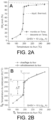
- Example 2 Evaluation of Ni10/UO 2+x catalyst at gas hourly space velocities of 15, 25 and 30 L/g/h under indirect Joule heating
- Example 2 The tests of Example 2 were carried out with the same reactor configuration as that of Example 1 in order to study the catalytic behavior of the catalyst containing 10% by mass of Ni relative to the total mass of catalyst, at higher gas hourly space velocities during the furnace temperature rise and fall phases. These tests make it possible in particular to determine whether a hysteresis (conversion deviation during the temperature rise and fall) can be observed.
- FIGS. 3A to 3D represent the evolution of the temperature of the catalytic bed T C as a function of the temperature of the furnace T F during the phase of temperature rise and fall of the furnace for the different values of hourly space velocity of gas equal to 15, 20, 25 and 30 L/g/h, in the presence of a gas flow containing a molar ratio H 2 /CO 2 equal to 4.
- the catalytic system according to the invention is capable of operating in “auto-methanation” mode when the gas hourly space velocity is at least 25 L/g/h (i.e. 25 m 3 /kg/h) and as long as the temperature of the catalytic bed remains at a value greater than or equal to 200°C, thanks to the establishment of a balance between the heat released by the reaction and the heat exchanged with the flow of reactants.
- Comparative tests were carried out under the same operating conditions as those of example 1, that is to say with a gas mixture whose H 2 /CO 2 molar ratio is 4 but in the presence of a catalyst comprising a mass content of nickel on an alumina type support (Al 2 O 3 ).
- the comparative catalyst was prepared as follows: the gamma-Al 2 O 3 support, hereinafter referred to as alumina, is in the form of extrudates (1 mm in diameter and 3 mm in length, Ketjen 300B supplied by Akzo Nobel) and is dry impregnated with an aqueous solution of nickel nitrate at room temperature. The material is allowed to mature at room temperature for 3 hours and then dried at 110 °C in air for 3 hours to remove the solvent. The dry material is calcined in air at 350 °C for 2 hours (with a temperature rise slope of 3 °C/min). The catalyst precursor thus obtained is reduced directly in the catalytic reactor under a flow of pure hydrogen (20 mL/min) at 350 °C for 2 hours.
- FIG. 5B shows the evolution of the temperature in the catalytic bed T C as a function of the furnace temperature T F during the phases of temperature rise and fall of the furnace.
- the furnace temperature exceeds 190 °C
- a significant jump in the temperature in the catalytic bed is measured (320 °C). This jump is explained by a higher conversion of CO 2 into CH 4 .
- the catalyst Ni10/Al 2 O 3 a very small difference is observed between the two temperatures, which reflects a lower conversion.
- the temperature in the Ni10/Al 2 O 3 catalytic bed is always higher than that measured in the Ni10/UO 2+x catalytic bed.
- the temperature measured in the catalytic bed containing Ni10/Al 2 O 3 catalyst is 320 °C while that measured in the catalytic bed containing Ni10/UO 2 catalyst is 220 °C.
- the lower catalytic activity of the Ni10/ Al2O3 catalyst is also manifested by the fact that the catalytic activity is not maintained when the furnace temperature is lowered and therefore by the absence of hysteresis in the temperature profile.
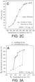
- Example 4 Evaluation of Ni20/UO 2+x catalyst at gas hourly space velocities of 20 L/g/h and 30 L/g/h under indirect Joule heating
- Tests were carried out with a catalyst comprising 20% by mass of nickel relative to the total mass of catalyst on a UO 2+x support.
- This catalyst was prepared according to the same protocol as that of example 1 with a double dry impregnation of an aqueous solution of nickel nitrate.
- the catalyst after reduction under hydrogen was tested under two gas hourly space velocities of 20 L/g/h and 30 L/g/h and with a gas mixture of H2 / CO2 molar ratio of 4.
- FIGS. 6A to 6C show respectively, for the temperature reduction phase of the furnace, the CH4 yield as a function of the furnace temperature T F , the variation of the temperature of the catalytic bed as a function of the furnace temperature and finally the CH4 yield as a function of the temperature of the catalytic bed T C .
- the catalyst according to the invention containing 20% by mass of Ni exhibits excellent catalytic activity.
- the CH 4 yield remains greater than 80% for a temperature range in the catalytic bed between 260 °C and 360 °C.
- the catalyst is capable of operating in the self-methanation mode during the temperature decrease of the furnace. For example, for an hourly gas space velocity of 30 L/g/h and a temperature of 90 °C measured in the furnace, the CH 4 yield remains greater than 80% thanks to the temperature maintenance of the catalytic bed at a value of approximately 260 °C.
- Example 5 Evaluation of Ni20/UO 2+x catalyst at low temperature and gas hourly space velocities of 20 L/g/h under inductive heating
- Tests were carried out with a catalyst comprising 20% by mass of nickel relative to the total mass of the catalyst on a UO 2+x support.
- the catalytic bed 13 which is contained in a glass reactor 14 with an internal diameter of 8 mm, comprises a layer 15 consisting of 800 mg of catalyst mixed with 200 mg of silicon carbide as a thermal diluent (SiC).
- the catalyst and SiC mixture is deposited above a graphite felt 16 acting as a susceptor.
- Reactor 14 is heated by means of an EasyHeat 8310, 10 kW induction heating system marketed by Ambrell Ltd. This system is equipped with a six-turn copper induction coil 19 which is cooled by water circulating inside the coil. The reactor is arranged inside the coil so that the catalyst bed is encircled by the induction coil. Real-time temperature control is provided by a Eurotherm 3504 controller connected to an Optris TM laser pyrometer pointing at the catalyst bed.
- the catalyst bed is gradually heated by induction to a temperature of 190 °C measured by the laser pyrometer. During the test, the temperature in the catalyst bed is fixed at the set temperature of 190 °C.
- the Ni20/UO 2+x catalyst has a stable CH 4 yield of approximately 62%, for a temperature in the catalytic bed of 190 °C. These results indicate that the Ni20/UO 2 catalyst allows the methanation reaction to be carried out at a relatively low temperature compared to the results reported in the literature.
- induction specifically heats only the solid catalyst and the susceptor and not the gaseous reactants passing through the catalytic bed, hence a significant gain in terms of energy input to the process. It should be noted that the catalyst does not exhibit any deactivation during the test, thus confirming the excellent stability of the latter.
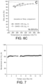
- Example 6 Evaluation of Ni20/UO 2+x catalyst at gas hourly space velocities of 20 L/g/h under inductive heating
- Example 6 differs from Example 5 in the conditions for heating the catalytic bed.
- the catalytic bed is gradually heated by induction to the set temperature of 170 °C with a current applied to the inductor of 120 amps. Then the set temperature is suddenly increased to 190 °C, which is accompanied by a temperature jump within the bed that reaches 230 °C.
- This exothermicity in the catalytic bed reflects a runaway catalytic reaction for the conversion of CO 2 .
- the current applied to the inductor is then reduced to 23 amps, then completely cut off, and finally the induction coil is moved so that the catalytic bed is outside its environment.
- the results of the conversion of CO2 into methane after stopping the inducer are presented in the figure 8 .
- the catalyst according to the invention achieves a conversion of approximately 80% of CO 2 into CH 4 in self-methanation mode (without external heat input) for 140 min.
- the temperature measured in the catalytic bed oscillates between 220 °C and 230 °C thanks to the heat released by the catalytic reaction.
Landscapes
- Chemical & Material Sciences (AREA)
- Organic Chemistry (AREA)
- Chemical Kinetics & Catalysis (AREA)
- Engineering & Computer Science (AREA)
- Materials Engineering (AREA)
- Oil, Petroleum & Natural Gas (AREA)
- General Chemical & Material Sciences (AREA)
- Physics & Mathematics (AREA)
- Thermal Sciences (AREA)
- Organic Low-Molecular-Weight Compounds And Preparation Thereof (AREA)
- Catalysts (AREA)
- Hydrogen, Water And Hydrids (AREA)
- Low-Molecular Organic Synthesis Reactions Using Catalysts (AREA)
Claims (15)
- Verfahren zur Umsetzung von CO2 in Methan, wobei:- Wasserstoff und eine CO2 umfassende Gasladung in Kontakt gebracht werden in mindestens einem Methanisierungsreaktor, der ein Katalysatorbett umfasst, bei einer Temperatur im katalytischen Bett zwischen 160 °C und 550 °C, bei einem Druck zwischen 0,1 MPa und 1 MPa, mit einer stundenbezogenen Gasraumgeschwindigkeit zwischen 10 m3/kg/h und 50 m3/kg/h und mit einem Molverhältnis H2/CO2 zwischen 1 und 8;- der Katalysator Metall Ni enthält, das auf einem Träger aus Uranoxid der Formel UO2+x abgeschieden ist, wobei x zwischen 0,01 und 0,6 liegt, und dessen Massengehalt an Nickel zwischen 5 % und 40 % Nickelmetall im Verhältnis zur Gesamtmasse des Katalysators liegt; und wobei:- der Katalysator durch ein Verfahren zubereitet wird, das die folgenden Schritte a) bis c) umfasst:a) Imprägnieren einer Vorstufe des Trägers, die im Wesentlichen aus einem Uranoxid (IV) und/oder aus Uran (VI) besteht, mit einer Lösung, die eine Vorstufe von Nickel und ein polares Lösungsmittel enthält;b) Kalzinieren mittels Luft und bei einer Temperatur von mindestens 250 °C der imprägnierten Vorstufe des Trägers; undc) Reduzieren der imprägnierten und kalzinierten Vorstufe des Trägers mittels Wasserstoff, bei einer Temperatur von mindestens 300 °C.
- Verfahren nach Anspruch 1, wobei vor dem Kalzinierungsschritt die imprägnierte Vorstufe des Trägers bei einer Temperatur unter 200 °C getrocknet wird.
- Verfahren nach Anspruch 1 oder Anspruch 2, wobei die Vorstufe des Trägers aus U3O8, UO2, UO4 und UO3 ausgewählt ist.
- Verfahren nach einem der Ansprüche 1 bis 3, wobei die Vorstufe des Trägers in Form von zylindrischen oder multilobären Extrudierungen, Kugeln, Ringen, Monolithen in Wabenstruktur oder Pulver vorliegt.
- Verfahren nach einem der Ansprüche 1 bis 4, wobei die Vorstufe von Nickel aus Hydroxid, Hydroxycarbonat, Carbonat und Nickelnitrat ausgewählt ist.
- Verfahren nach einem der Ansprüche 1 bis 5, wobei der Imprägnierungsschritt a) eine Trocken- oder Überschussimprägnierung implementiert.
- Verfahren nach einem der Ansprüche 1 bis 6, wobei der Reduzierungsschritt c) in situ im Methanisierungsreaktor durchgeführt wird.
- Verfahren nach einem der Ansprüche 1 bis 7, wobei die CO2 umfassende Gasladung und der Wasserstoff getrennt oder vermischt in einer Abwärtsrichtung in den Methanisierungsreaktor geleitet werden.
- Verfahren nach einem der Ansprüche 1 bis 8, wobei der Methanisierungsreaktor ein adiabatischer Reaktor ist.
- Verfahren nach einem der Ansprüche 1 bis 9, wobei der Methanisierungsreaktor ein Reaktor mit festem oder verwirbeltem Katalysatorbett ist.
- Verfahren nach Anspruch 10, wobei das Katalysatorbett ein festes Bett ist und das Katalysatorbett einem elektromagnetischen Wechselfeld ausgesetzt wird, um das Katalysatorbett durch Induktion zu erwärmen.
- Verfahren nach Anspruch 11, wobei das feste Bett des Katalysators ferner Suszeptorpartikel umfasst.
- Verfahren nach einem der Ansprüche 1 bis 12, wobei das Verfahren mit einer erneuerbaren Energiequelle durchgeführt wird.
- Verfahren nach einem der Ansprüche 1 bis 13, wobei der Reaktor ein Reaktor mit festem Katalysatorbett ist und wobei die stundenbezogene Gasraumgeschwindigkeit auf mindestens 15 m3/kg/h festgelegt wird, um eine Temperatur des Katalysatorbetts TC bei mindestens 200 °C zu halten, wodurch die Umsetzungsreaktion ohne externe Wärmezufuhr durchgeführt wird.
- Verfahren zur Zubereitung eines Katalysators der Methanisierung von CO2, der Nickelmetall umfasst, das auf einem Träger aus Uranoxid der Formel UO2+x abgeschieden ist, wobei x zwischen 0,01 und 0,6 liegt und wobei der Massengehalt an Nickel zwischen 5 % und 40 % Nickelmetall im Verhältnis zur Gesamtmasse des Katalysators liegt, wobei das Verfahren die folgenden Schritte a) bis c) umfasst:a) Imprägnieren einer Vorstufe des Trägers, die im Wesentlichen aus einem Uranoxid (IV) und/oder aus Uran (VI) besteht, mit einer Lösung, die eine Vorstufe von Nickel und ein polares Lösungsmittel enthält;b) Kalzinieren mittels Luft und bei einer Temperatur von mindestens 250 °C der imprägnierten Vorstufe des Trägers; undc) Reduzieren der imprägnierten und kalzinierten Vorstufe des Trägers mittels Wasserstoff, bei einer Temperatur von mindestens 300 °C.
Applications Claiming Priority (2)
| Application Number | Priority Date | Filing Date | Title |
|---|---|---|---|
| FR2104508A FR3122425B1 (fr) | 2021-04-29 | 2021-04-29 | Procédé de conversion du CO2 en méthane |
| PCT/FR2022/050745 WO2022229541A1 (fr) | 2021-04-29 | 2022-04-21 | Procédé de conversion du co2 en méthane |
Publications (2)
| Publication Number | Publication Date |
|---|---|
| EP4313403A1 EP4313403A1 (de) | 2024-02-07 |
| EP4313403B1 true EP4313403B1 (de) | 2025-02-26 |
Family
ID=77180102
Family Applications (1)
| Application Number | Title | Priority Date | Filing Date |
|---|---|---|---|
| EP22735497.4A Active EP4313403B1 (de) | 2021-04-29 | 2022-04-21 | Verfahren zur umwandlung von co2 in methan |
Country Status (6)
| Country | Link |
|---|---|
| US (1) | US20240217894A1 (de) |
| EP (1) | EP4313403B1 (de) |
| JP (1) | JP2024516009A (de) |
| CN (1) | CN117396274A (de) |
| FR (1) | FR3122425B1 (de) |
| WO (1) | WO2022229541A1 (de) |
Families Citing this family (3)
| Publication number | Priority date | Publication date | Assignee | Title |
|---|---|---|---|---|
| WO2025121168A1 (ja) * | 2023-12-08 | 2025-06-12 | 日本碍子株式会社 | ガス反応合成ユニット及びガス反応合成装置 |
| KR20250097096A (ko) * | 2023-12-21 | 2025-06-30 | 울산과학기술원 | 기계화학적 이산화탄소 전환방법 |
| CN121244220B (zh) * | 2025-12-05 | 2026-03-20 | 苏州大学 | 一种锕系金属催化剂在二氧化碳甲烷化反应中的应用 |
Family Cites Families (8)
| Publication number | Priority date | Publication date | Assignee | Title |
|---|---|---|---|---|
| GB1324505A (en) * | 1969-10-21 | 1973-07-25 | Gas Council | Steam reforming catalyst |
| US4032556A (en) * | 1971-11-23 | 1977-06-28 | The Gas Council | Methanation of gases |
| US4402868A (en) * | 1980-12-08 | 1983-09-06 | Texaco Inc. | Catalyst for the production of methane-rich gas |
| US4341531A (en) * | 1980-12-08 | 1982-07-27 | Texaco Inc. | Production of methane-rich gas |
| RU2350386C1 (ru) * | 2007-12-06 | 2009-03-27 | Институт катализа им. Г.К. Борескова Сибирского отделения Российской академии наук (статус государственного учреждения) | Катализатор, способ его приготовления и способ получения синтез-газа из метана |
| WO2016116542A1 (en) * | 2015-01-21 | 2016-07-28 | Université De Strasbourg | Method for preparing highly nitrogen-doped mesoporous carbon composites |
| CN106281464B (zh) * | 2016-08-29 | 2020-04-10 | 清华大学 | 一种甲烷二氧化碳催化重整制备合成气的方法 |
| CN108311154A (zh) * | 2018-02-02 | 2018-07-24 | 济南大学 | 一种用于co2甲烷化新型镍基催化剂的改性及制备方法 |
-
2021
- 2021-04-29 FR FR2104508A patent/FR3122425B1/fr active Active
-
2022
- 2022-04-21 EP EP22735497.4A patent/EP4313403B1/de active Active
- 2022-04-21 JP JP2023566944A patent/JP2024516009A/ja active Pending
- 2022-04-21 US US18/557,410 patent/US20240217894A1/en active Pending
- 2022-04-21 WO PCT/FR2022/050745 patent/WO2022229541A1/fr not_active Ceased
- 2022-04-21 CN CN202280035030.9A patent/CN117396274A/zh active Pending
Also Published As
| Publication number | Publication date |
|---|---|
| FR3122425B1 (fr) | 2025-09-19 |
| EP4313403A1 (de) | 2024-02-07 |
| US20240217894A1 (en) | 2024-07-04 |
| WO2022229541A1 (fr) | 2022-11-03 |
| JP2024516009A (ja) | 2024-04-11 |
| FR3122425A1 (fr) | 2022-11-04 |
| CN117396274A (zh) | 2024-01-12 |
Similar Documents
| Publication | Publication Date | Title |
|---|---|---|
| EP4313403B1 (de) | Verfahren zur umwandlung von co2 in methan | |
| Bohn et al. | Stabilizing iron oxide used in cycles of reduction and oxidation for hydrogen production | |
| CN102083745B (zh) | 运行hts反应器的方法 | |
| CN102355948B (zh) | 用于生产合成气的镍/氧化镧催化剂 | |
| US10654772B2 (en) | Selective oxidative dehydrogenation of propane to propylene | |
| EP3283216B1 (de) | Katalysator mit einer bor-dotierten phase | |
| EP1333009A1 (de) | Verfahren zur partialoxidation von methan unter verwendung einer dichten, sauerstoffselektiven keramischen permeationsmembran | |
| CN1812930A (zh) | 催化剂、蒸汽重整系统和方法、制造蒸汽重整催化剂的方法 | |
| JPWO2010134326A1 (ja) | タール含有ガス改質用触媒、タール含有ガス改質用触媒の製造方法、タール含有ガス改質用触媒を用いたタール含有ガス改質方法、及びタール含有ガス改質用触媒の再生方法 | |
| JP2019155227A (ja) | Co2メタン化触媒及びこれを用いた二酸化炭素の還元方法 | |
| EP4237140A1 (de) | Gemischtes katalytisches system zur umwandlung von co2 und/oder co in einem hybriden kaltplasmakatalyseverfahren | |
| JP6631245B2 (ja) | 炭化水素の改質用触媒の製造方法及び軽質炭化水素の改質方法 | |
| WO2023170560A1 (fr) | Procédé et catalyseurs pour le reformage du méthane en plasma catalyse | |
| EP3643767A1 (de) | Fischer-tropsch-syntheseverfahren, das einen katalysator umfasst, der durch zugabe einer organischen verbindung in der gasphase erzeugt wird | |
| JP2023544885A (ja) | コバルトを少なくとも40重量%含有するフィッシャー-トロプシュ(Fischer-Tropsch)触媒、それを使用するフィッシャー-トロプシュ(Fischer-Tropsch)方法、及びその作製方法 | |
| CA2937240C (fr) | Procede de preparation d'un catalyseur destine a etre mis en oeuvre dans une reaction fischer-tropsch | |
| KR102613843B1 (ko) | 수소 생산용 촉매, 이의 제조 방법 및 이를 이용한 수소 생산 방법 | |
| WO2023170562A1 (fr) | Procédé et catalyseur pour la production d'hydrogène par décomposition de l'ammoniac en plasma catalyse | |
| JP2000086201A (ja) | 水素の製造方法 | |
| RU2857219C2 (ru) | Способ превращения со2 в метан | |
| FR2989682A1 (fr) | Procede d'alcanation du co2 utilisant comme catalyseur un compose comprenant du nickel sur un support a base d'oxyde de cerium | |
| JP2019037905A (ja) | 低温メタン改質触媒活物質 | |
| JP5268069B2 (ja) | メタンの水蒸気改質触媒 | |
| KR101842581B1 (ko) | 자립형 셀프서스테이닝 방식의 열교환기타입 모듈형 리포머 | |
| KR101830954B1 (ko) | 일산화탄소 제거부가 포함된 수소제조 반응기 |
Legal Events
| Date | Code | Title | Description |
|---|---|---|---|
| STAA | Information on the status of an ep patent application or granted ep patent |
Free format text: STATUS: UNKNOWN |
|
| STAA | Information on the status of an ep patent application or granted ep patent |
Free format text: STATUS: THE INTERNATIONAL PUBLICATION HAS BEEN MADE |
|
| PUAI | Public reference made under article 153(3) epc to a published international application that has entered the european phase |
Free format text: ORIGINAL CODE: 0009012 |
|
| STAA | Information on the status of an ep patent application or granted ep patent |
Free format text: STATUS: REQUEST FOR EXAMINATION WAS MADE |
|
| 17P | Request for examination filed |
Effective date: 20231024 |
|
| AK | Designated contracting states |
Kind code of ref document: A1 Designated state(s): AL AT BE BG CH CY CZ DE DK EE ES FI FR GB GR HR HU IE IS IT LI LT LU LV MC MK MT NL NO PL PT RO RS SE SI SK SM TR |
|
| DAV | Request for validation of the european patent (deleted) | ||
| DAX | Request for extension of the european patent (deleted) | ||
| GRAP | Despatch of communication of intention to grant a patent |
Free format text: ORIGINAL CODE: EPIDOSNIGR1 |
|
| STAA | Information on the status of an ep patent application or granted ep patent |
Free format text: STATUS: GRANT OF PATENT IS INTENDED |
|
| RIC1 | Information provided on ipc code assigned before grant |
Ipc: B01J 37/08 20060101ALI20240927BHEP Ipc: B01J 35/61 20240101ALI20240927BHEP Ipc: C07C 1/12 20060101ALI20240927BHEP Ipc: B01J 23/755 20060101ALI20240927BHEP Ipc: B01J 23/83 20060101ALI20240927BHEP Ipc: C12P 5/02 20060101ALI20240927BHEP Ipc: B01J 37/02 20060101ALI20240927BHEP Ipc: B01J 37/03 20060101ALI20240927BHEP Ipc: C10L 3/08 20060101ALI20240927BHEP Ipc: B01J 23/12 20060101AFI20240927BHEP |
|
| INTG | Intention to grant announced |
Effective date: 20241018 |
|
| GRAS | Grant fee paid |
Free format text: ORIGINAL CODE: EPIDOSNIGR3 |
|
| GRAA | (expected) grant |
Free format text: ORIGINAL CODE: 0009210 |
|
| STAA | Information on the status of an ep patent application or granted ep patent |
Free format text: STATUS: THE PATENT HAS BEEN GRANTED |
|
| AK | Designated contracting states |
Kind code of ref document: B1 Designated state(s): AL AT BE BG CH CY CZ DE DK EE ES FI FR GB GR HR HU IE IS IT LI LT LU LV MC MK MT NL NO PL PT RO RS SE SI SK SM TR |
|
| REG | Reference to a national code |
Ref country code: GB Ref legal event code: FG4D Free format text: NOT ENGLISH |
|
| REG | Reference to a national code |
Ref country code: CH Ref legal event code: EP |
|
| REG | Reference to a national code |
Ref country code: DE Ref legal event code: R096 Ref document number: 602022011199 Country of ref document: DE |
|
| REG | Reference to a national code |
Ref country code: IE Ref legal event code: FG4D Free format text: LANGUAGE OF EP DOCUMENT: FRENCH |
|
| REG | Reference to a national code |
Ref country code: NL Ref legal event code: FP |
|
| PGFP | Annual fee paid to national office [announced via postgrant information from national office to epo] |
Ref country code: NL Payment date: 20250423 Year of fee payment: 4 |
|
| PG25 | Lapsed in a contracting state [announced via postgrant information from national office to epo] |
Ref country code: RS Free format text: LAPSE BECAUSE OF FAILURE TO SUBMIT A TRANSLATION OF THE DESCRIPTION OR TO PAY THE FEE WITHIN THE PRESCRIBED TIME-LIMIT Effective date: 20250526 |
|
| PG25 | Lapsed in a contracting state [announced via postgrant information from national office to epo] |
Ref country code: FI Free format text: LAPSE BECAUSE OF FAILURE TO SUBMIT A TRANSLATION OF THE DESCRIPTION OR TO PAY THE FEE WITHIN THE PRESCRIBED TIME-LIMIT Effective date: 20250226 |
|
| PG25 | Lapsed in a contracting state [announced via postgrant information from national office to epo] |
Ref country code: PL Free format text: LAPSE BECAUSE OF FAILURE TO SUBMIT A TRANSLATION OF THE DESCRIPTION OR TO PAY THE FEE WITHIN THE PRESCRIBED TIME-LIMIT Effective date: 20250226 |
|
| PGFP | Annual fee paid to national office [announced via postgrant information from national office to epo] |
Ref country code: DE Payment date: 20250417 Year of fee payment: 4 |
|
| PG25 | Lapsed in a contracting state [announced via postgrant information from national office to epo] |
Ref country code: ES Free format text: LAPSE BECAUSE OF FAILURE TO SUBMIT A TRANSLATION OF THE DESCRIPTION OR TO PAY THE FEE WITHIN THE PRESCRIBED TIME-LIMIT Effective date: 20250226 |
|
| REG | Reference to a national code |
Ref country code: LT Ref legal event code: MG9D |
|
| PG25 | Lapsed in a contracting state [announced via postgrant information from national office to epo] |
Ref country code: IS Free format text: LAPSE BECAUSE OF FAILURE TO SUBMIT A TRANSLATION OF THE DESCRIPTION OR TO PAY THE FEE WITHIN THE PRESCRIBED TIME-LIMIT Effective date: 20250626 Ref country code: NO Free format text: LAPSE BECAUSE OF FAILURE TO SUBMIT A TRANSLATION OF THE DESCRIPTION OR TO PAY THE FEE WITHIN THE PRESCRIBED TIME-LIMIT Effective date: 20250526 |
|
| PG25 | Lapsed in a contracting state [announced via postgrant information from national office to epo] |
Ref country code: HR Free format text: LAPSE BECAUSE OF FAILURE TO SUBMIT A TRANSLATION OF THE DESCRIPTION OR TO PAY THE FEE WITHIN THE PRESCRIBED TIME-LIMIT Effective date: 20250226 |
|
| PG25 | Lapsed in a contracting state [announced via postgrant information from national office to epo] |
Ref country code: PT Free format text: LAPSE BECAUSE OF FAILURE TO SUBMIT A TRANSLATION OF THE DESCRIPTION OR TO PAY THE FEE WITHIN THE PRESCRIBED TIME-LIMIT Effective date: 20250626 Ref country code: LV Free format text: LAPSE BECAUSE OF FAILURE TO SUBMIT A TRANSLATION OF THE DESCRIPTION OR TO PAY THE FEE WITHIN THE PRESCRIBED TIME-LIMIT Effective date: 20250226 |
|
| PGFP | Annual fee paid to national office [announced via postgrant information from national office to epo] |
Ref country code: FR Payment date: 20250422 Year of fee payment: 4 |
|
| PG25 | Lapsed in a contracting state [announced via postgrant information from national office to epo] |
Ref country code: BG Free format text: LAPSE BECAUSE OF FAILURE TO SUBMIT A TRANSLATION OF THE DESCRIPTION OR TO PAY THE FEE WITHIN THE PRESCRIBED TIME-LIMIT Effective date: 20250226 Ref country code: GR Free format text: LAPSE BECAUSE OF FAILURE TO SUBMIT A TRANSLATION OF THE DESCRIPTION OR TO PAY THE FEE WITHIN THE PRESCRIBED TIME-LIMIT Effective date: 20250527 |
|
| REG | Reference to a national code |
Ref country code: AT Ref legal event code: MK05 Ref document number: 1770125 Country of ref document: AT Kind code of ref document: T Effective date: 20250226 |
|
| PG25 | Lapsed in a contracting state [announced via postgrant information from national office to epo] |
Ref country code: SE Free format text: LAPSE BECAUSE OF FAILURE TO SUBMIT A TRANSLATION OF THE DESCRIPTION OR TO PAY THE FEE WITHIN THE PRESCRIBED TIME-LIMIT Effective date: 20250226 |
|
| PG25 | Lapsed in a contracting state [announced via postgrant information from national office to epo] |
Ref country code: SM Free format text: LAPSE BECAUSE OF FAILURE TO SUBMIT A TRANSLATION OF THE DESCRIPTION OR TO PAY THE FEE WITHIN THE PRESCRIBED TIME-LIMIT Effective date: 20250226 |
|
| PG25 | Lapsed in a contracting state [announced via postgrant information from national office to epo] |
Ref country code: DK Free format text: LAPSE BECAUSE OF FAILURE TO SUBMIT A TRANSLATION OF THE DESCRIPTION OR TO PAY THE FEE WITHIN THE PRESCRIBED TIME-LIMIT Effective date: 20250226 |
|
| PG25 | Lapsed in a contracting state [announced via postgrant information from national office to epo] |
Ref country code: IT Free format text: LAPSE BECAUSE OF FAILURE TO SUBMIT A TRANSLATION OF THE DESCRIPTION OR TO PAY THE FEE WITHIN THE PRESCRIBED TIME-LIMIT Effective date: 20250226 |
|
| PG25 | Lapsed in a contracting state [announced via postgrant information from national office to epo] |
Ref country code: AT Free format text: LAPSE BECAUSE OF FAILURE TO SUBMIT A TRANSLATION OF THE DESCRIPTION OR TO PAY THE FEE WITHIN THE PRESCRIBED TIME-LIMIT Effective date: 20250226 |
|
| PG25 | Lapsed in a contracting state [announced via postgrant information from national office to epo] |
Ref country code: EE Free format text: LAPSE BECAUSE OF FAILURE TO SUBMIT A TRANSLATION OF THE DESCRIPTION OR TO PAY THE FEE WITHIN THE PRESCRIBED TIME-LIMIT Effective date: 20250226 Ref country code: CZ Free format text: LAPSE BECAUSE OF FAILURE TO SUBMIT A TRANSLATION OF THE DESCRIPTION OR TO PAY THE FEE WITHIN THE PRESCRIBED TIME-LIMIT Effective date: 20250226 |
|
| PG25 | Lapsed in a contracting state [announced via postgrant information from national office to epo] |
Ref country code: RO Free format text: LAPSE BECAUSE OF FAILURE TO SUBMIT A TRANSLATION OF THE DESCRIPTION OR TO PAY THE FEE WITHIN THE PRESCRIBED TIME-LIMIT Effective date: 20250226 |
|
| PG25 | Lapsed in a contracting state [announced via postgrant information from national office to epo] |
Ref country code: SK Free format text: LAPSE BECAUSE OF FAILURE TO SUBMIT A TRANSLATION OF THE DESCRIPTION OR TO PAY THE FEE WITHIN THE PRESCRIBED TIME-LIMIT Effective date: 20250226 |
|
| REG | Reference to a national code |
Ref country code: CH Ref legal event code: H13 Free format text: ST27 STATUS EVENT CODE: U-0-0-H10-H13 (AS PROVIDED BY THE NATIONAL OFFICE) Effective date: 20251125 |
|
| REG | Reference to a national code |
Ref country code: DE Ref legal event code: R097 Ref document number: 602022011199 Country of ref document: DE |
|
| PG25 | Lapsed in a contracting state [announced via postgrant information from national office to epo] |
Ref country code: LU Free format text: LAPSE BECAUSE OF NON-PAYMENT OF DUE FEES Effective date: 20250421 |
|
| PG25 | Lapsed in a contracting state [announced via postgrant information from national office to epo] |
Ref country code: MC Free format text: LAPSE BECAUSE OF FAILURE TO SUBMIT A TRANSLATION OF THE DESCRIPTION OR TO PAY THE FEE WITHIN THE PRESCRIBED TIME-LIMIT Effective date: 20250226 |
|
| REG | Reference to a national code |
Ref country code: BE Ref legal event code: MM Effective date: 20250430 |
|
| PLBE | No opposition filed within time limit |
Free format text: ORIGINAL CODE: 0009261 |
|
| STAA | Information on the status of an ep patent application or granted ep patent |
Free format text: STATUS: NO OPPOSITION FILED WITHIN TIME LIMIT |
|
| PG25 | Lapsed in a contracting state [announced via postgrant information from national office to epo] |
Ref country code: BE Free format text: LAPSE BECAUSE OF NON-PAYMENT OF DUE FEES Effective date: 20250430 |
|
| PG25 | Lapsed in a contracting state [announced via postgrant information from national office to epo] |
Ref country code: CH Free format text: LAPSE BECAUSE OF NON-PAYMENT OF DUE FEES Effective date: 20250430 |
|
| 26N | No opposition filed |
Effective date: 20251127 |
|
| PG25 | Lapsed in a contracting state [announced via postgrant information from national office to epo] |
Ref country code: IE Free format text: LAPSE BECAUSE OF NON-PAYMENT OF DUE FEES Effective date: 20250421 |