EP4313341B1 - Modular construction system motor unit - Google Patents
Modular construction system motor unit Download PDFInfo
- Publication number
- EP4313341B1 EP4313341B1 EP22718149.2A EP22718149A EP4313341B1 EP 4313341 B1 EP4313341 B1 EP 4313341B1 EP 22718149 A EP22718149 A EP 22718149A EP 4313341 B1 EP4313341 B1 EP 4313341B1
- Authority
- EP
- European Patent Office
- Prior art keywords
- gear
- outtake
- motor unit
- power outtake
- casing
- Prior art date
- Legal status (The legal status is an assumption and is not a legal conclusion. Google has not performed a legal analysis and makes no representation as to the accuracy of the status listed.)
- Active
Links
Images


Classifications
-
- A—HUMAN NECESSITIES
- A63—SPORTS; GAMES; AMUSEMENTS
- A63H—TOYS, e.g. TOPS, DOLLS, HOOPS OR BUILDING BLOCKS
- A63H33/00—Other toys
- A63H33/04—Building blocks, strips, or similar building parts
- A63H33/042—Mechanical, electrical, optical, pneumatic or hydraulic arrangements; Motors
-
- H—ELECTRICITY
- H02—GENERATION; CONVERSION OR DISTRIBUTION OF ELECTRIC POWER
- H02K—DYNAMO-ELECTRIC MACHINES
- H02K7/00—Arrangements for handling mechanical energy structurally associated with dynamo-electric machines, e.g. structural association with mechanical driving motors or auxiliary dynamo-electric machines
- H02K7/14—Structural association with mechanical loads, e.g. with hand-held machine tools or fans
-
- A—HUMAN NECESSITIES
- A63—SPORTS; GAMES; AMUSEMENTS
- A63H—TOYS, e.g. TOPS, DOLLS, HOOPS OR BUILDING BLOCKS
- A63H33/00—Other toys
- A63H33/04—Building blocks, strips, or similar building parts
- A63H33/06—Building blocks, strips, or similar building parts to be assembled without the use of additional elements
- A63H33/08—Building blocks, strips, or similar building parts to be assembled without the use of additional elements provided with complementary holes, grooves, or protuberances, e.g. dovetails
- A63H33/086—Building blocks, strips, or similar building parts to be assembled without the use of additional elements provided with complementary holes, grooves, or protuberances, e.g. dovetails with primary projections fitting by friction in complementary spaces between secondary projections, e.g. sidewalls
-
- H—ELECTRICITY
- H02—GENERATION; CONVERSION OR DISTRIBUTION OF ELECTRIC POWER
- H02K—DYNAMO-ELECTRIC MACHINES
- H02K11/00—Structural association of dynamo-electric machines with electric components or with devices for shielding, monitoring or protection
- H02K11/20—Structural association of dynamo-electric machines with electric components or with devices for shielding, monitoring or protection for measuring, monitoring, testing, protecting or switching
- H02K11/21—Devices for sensing speed or position, or actuated thereby
-
- H—ELECTRICITY
- H02—GENERATION; CONVERSION OR DISTRIBUTION OF ELECTRIC POWER
- H02K—DYNAMO-ELECTRIC MACHINES
- H02K7/00—Arrangements for handling mechanical energy structurally associated with dynamo-electric machines, e.g. structural association with mechanical driving motors or auxiliary dynamo-electric machines
- H02K7/10—Structural association with clutches, brakes, gears, pulleys or mechanical starters
- H02K7/116—Structural association with clutches, brakes, gears, pulleys or mechanical starters with gears
-
- H—ELECTRICITY
- H02—GENERATION; CONVERSION OR DISTRIBUTION OF ELECTRIC POWER
- H02K—DYNAMO-ELECTRIC MACHINES
- H02K2213/00—Specific aspects, not otherwise provided for and not covered by codes H02K2201/00 - H02K2211/00
- H02K2213/03—Machines characterised by numerical values, ranges, mathematical expressions or similar information
-
- H—ELECTRICITY
- H02—GENERATION; CONVERSION OR DISTRIBUTION OF ELECTRIC POWER
- H02K—DYNAMO-ELECTRIC MACHINES
- H02K2213/00—Specific aspects, not otherwise provided for and not covered by codes H02K2201/00 - H02K2211/00
- H02K2213/12—Machines characterised by the modularity of some components
Definitions
- the present invention relates to a modular construction system and a modular construction system motor unit.
- Modular construction systems as such are known in the art, as is modular construction system motor units, or simple motor units, for such modular construction systems.
- Modular construction systems comprises a plurality of construction elements, for example building blocks or bricks, which - when connected together - may be assembled to form a variety of different building structures.
- Motor units may be added to such modular construction systems in order to make parts of such system move.
- Modular construction systems are "modular" in the sense that the construction elements making up the construction systems are sized and shaped and comprise cooperating connection means allowing their interconnection, such that models/sets, such as figures robots, etc. may be constructed.
- Modular construction elements as they are known from traditional modular construction systems, such as beams, plates, bricks, pegs, connectors, cog-wheels, etc., may be combined with functional modular construction elements, such as lighting elements, motors/actuators, sensors, but also programmable processor units, which may also be digitally connectable with external devices, e.g. for programming or remote control.
- Such modular construction systems with enhanced functionality have proven their value in a play and/or learning context, not the least because they facilitate reliable, yet easily detachable mechanical connections between simple and functional modular construction elements, and because the functional modular construction elements are adapted to each other to provide a positive and stimulating user experience.
- a motor unit for such a modular construction system often comprises a power outtake disc comprising connection means suitable for connecting for example an axle or the like.
- the motor unit of a modular construction system may comprise an encoder, such as a magnet sensor with 360-degree resolution a regulated absolute position motor with 0-point indicator (zero-point indicator).
- the motor units In modular construction systems the motor units often comprises a casing and other parts, such as a gear mechanism, comprising parts formed in plastic, in order to keep cost low, and they may thereby be easily connectable to other construction elements also formed in plastic.
- the motor units of the modular construction systems are often quite small, but still may be used in construction of quite large structures. Therefore, during use, a large - and sometimes asymmetric - load, may be applied to an outtake disc of the motor unit.
- WO2020121189A1 discloses a modular robotic system, and methods for configuring the robotic module.
- the robotic system includes a first housing comprising a first processor and a first connector, a second housing comprising a second processor and a second connector, the first connector of the first housing being connectable to the second connector of the second housing in a plurality of orientations relative to one another, where the first processor and the second processor are configured to communicate with one other when connected in any of the plurality of orientations.
- a modular construction system motor unit for a modular construction system comprising
- backlash In mechanical engineering, backlash, sometimes called lash or play, is a clearance or lost motion in a mechanism caused by gaps between parts.
- the cooperating shapes and sizes of the receptacle and the first rotation transfer part are configured such that a clearance, i.e. a gap is provided between them.
- the backlash allows a slight rotation of the power outtake element before the first rotation transfer part is engaged for rotation with the outtake element.
- the gearing mechanism is configured for transferring rotation from the electrical motor to the power outtake element.
- the gearing mechanism is provided within the casing.
- the rotation sensing mechanism is provided within the casing.
- the cooperating shapes and sizes of the receptacle and the first rotation transfer part are configured such that the receptacle is allowed to rotate 0.5-2° before the first rotation transfer part is engaged for rotation with the outtake element.
- the disc element is connected to the power outtake element via a first axle.
- the disc element is arranged at a sidewall of the casing opposite to the power outtake element relative to the casing.
- some of the gears of the gear mechanism are coaxially arranged surround by and supporting the first axle.
- the first rotation transfer part comprises a cylindrical main body part and a first arm protruding therefrom, and where the receptacle comprises a cylindrical main trough and a first arm trough extending therefrom.
- the first arm of the first rotation transfer part preferably extends perpendicular to a cylindrical outer surface of the first rotation transfer part.
- the first trough arm of the receptacle preferably extends perpendicular to a cylindrical inner surface of the receptacle.
- the first arm of the first rotation transfer part extends perpendicular to the rotational axis of the outtake element.
- the first trough arm of the receptacle preferably extends perpendicular to the rotational axis of the outtake element.
- the first arm of the first rotation transfer part has a first width
- the first trough arm of the receptacle has a second width, wherein the first width is 1-2 mm smaller than the second width
- a modular construction system comprising a modular construction system motor unit according to any one of the embodiments of the first aspect of the invention, and a plurality of construction elements.
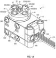
- Fig. 1A in a perspective view, shows a modular construction system motor unit 1 according to an aspect of the invention and for a modular construction system according to another aspect of the invention.
- the modular construction system motor unit 1 may simply be referred to as motor unit 1.
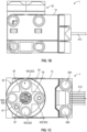
- Fig. 1B shows a side view of the motor unit 1 of Fig. 1A
- Fig. 1C shows a top view of the motor unit 1 of Fig. 1A .
- the motor unit 1 comprises a casing 10 and an electrical motor 150 mounted inside of the casing 10.
- the electrical motor 150 is not shown in Fig. 1A , but is visible in Figs. 2 and 5 .
- the motor unit 1 further comprises a power outtake element 20, or simply outtake element 20, which extends from the casing 10, and is connected thereto in such a way the outtake element 20 may rotate relative to the casing 10.
- the outtake element 20 is rotationally connected relative to the casing 10 about a rotational axis (not shown).
- the outtake element 20 is connected to the electrical motor 150 such that when an output axle 151, see Fig. 2 and 5 , of the electrical motor 150 rotates, the outtake element 20 is forced to rotate too.
- the outtake element 20 is preferably connected to the electrical motor 150 via a gear mechanism, for example as illustrated in Figs. 3 , 4 , 5 . 6 , and 7A-C .
- the outtake element 20 is provided with at least one connector 600 for connecting the motor unit 1 to a construction element 510, 520 of a modular construction system.
- the outtake element 20 comprises five such connectors 600.
- first connector 601 In the center of the outtake element 20, one connector 600, first connector 601 is shown.
- the first connector 601 takes the form of an indention into the outtake element 20, which has an X-shaped (cross shaped) cross section (the cross section taken perpendicular to the rotational axis of the outtake element 20).
- the first connector is configured for receiving an axle 524, as shown in Fig. 11 , the axle 524 having a cross sectional shape (taken perpendicular to a longitudinal axis of the axle 524), corresponding to the cross sectional shape of the first connector 601, i.e. the axle has an X-shaped (cross shaped) cross section.
- the first connector 601 and an axle 524, as described, and belonging to a modular construction system 500 are dimensioned such that the first connector 601 and the axle may form a friction fit there between.
- the second connectors are formed as indentions into and through the outtake element 20.
- the second connectors are preferably connector openings 640, as will be described in connection with Fig. 8 , 10 and 11 below.
- the outtake element 20 may have only a centrally located connector 600, such as the first connector, and no connectors at the periphery.
- the outtake element 20 may have only connectors at the periphery, such as the second connectors 602, mentioned above, and no central first connector 601.
- the number, form and location (on the outtake element 20) of the connectors 600 may be different than shown in Fig. 1A .
- the one or more connectors 600 are configured for cooperating with and connecting to various types of construction elements of a modular construction system for example as described below.
- the casing 10 of the motor unit 1 further has a plurality of connector openings 640, which will be described in connection with Fig. 8 , 10 and 11 below, formed therein, in order to allow connection of the motor unit 1 to other construction elements of a modular construction system 500. Again it will be appreciated that other types of connecting means may be formed on the casing 10.
- the motor unit 1 may form part of a modular construction system 500 comprising a plurality of construction elements.
- a modular construction system 500 and exemplary construction elements will be described in more detail, before returning to the motor unit 1.
- Fig. 9 illustrates, in a see-through perspective view, a prior art construction element 511 belonging to a first type of construction elements.
- Such first type of construction elements comprises at least connector knobs 610 configured for connecting to similar but variously shaped other construction elements of the first type having knob receiving openings 620.
- the construction element 511 shown in Fig. 9 has connector knobs 610 formed on an upper surface thereof and knob receiving openings 620 formed in an opposite surface thereof. It will be appreciated that for example two construction elements 511 as shown in Fig. 10 may be connected to each other by connecting the connector knobs 610 of one construction element 511 to a corresponding number of connector openings 620 of a second construction element 511.
- the connector knobs 610 and the knob receiving openings 620 form friction fits/friction connections by an outer diameter of the cylindrical connector knobs 610 being closely adapted to the dimensioning of one or more surfaces of the knob receiving openings 620.
- the construction element 511 shown in Fig. 9 has eight connector knobs 610 and eight knob receiving openings 620.
- the connector knobs 610 are arranged in a regular two-dimensional lattice, in this case a 2 ⁇ 4 lattice.
- the knob receiving openings 620 are arranged in a regular two-dimensional lattice, in this case a 2 ⁇ 4 lattice.
- the construction element 511 shown in Fig. 9 is shaped as a brick.
- FIG. 8 Another construction element 512 of the first type construction elements is shown in Fig. 8 .
- the construction element 512 shown in Fig. 8 is formed as a plate, and comprises 64 connector knobs 610 formed in an 8 ⁇ 8 lattice, and 64 knob receiving openings knobs 620 (not shown), also arranged in a 8 ⁇ 8 lattice, on the opposite side of the plate relative to the connector knobs 610.
- Construction elements of the first type construction elements are herein defined as having either connector knobs 610 or knob receiving openings 620, or both.
- a first type construction system is herein defined as a system of construction elements comprising two or more first type construction elements, where at least one construction element has connector knobs 610 arranged in a regular two-dimensional n ⁇ n lattice, where n ⁇ 2.
- a first type construction system is known in the art, e.g. under the trade name LEGO SYSTEM ⁇ , marketed by LEGO A/S.
- Fig. 10 shows a second type construction element 521 having two cylindrical connector portions 630 formed along a common axis and facing away from each other.
- Second type construction element 520 may additionally or alternatively comprise cylindrical connector openings 640 configured for cooperating with other second type construction elements 520 having protruding cylindrical connector portions 630, such as e.g. a second type construction element 521 shown in Fig. 10 .
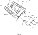
- Fig. 11 shows an example of a second type construction system 520 comprising second type construction elements 521, 522, 523, 524, 525 having various shapes and forms and various connection means.
- the second type construction element 521 shown in Fig. 10 comprises two cylindrical connector portions 630 or resilient connector pegs, each being configured to form a snap connection with a connector opening 640 formed on another second type of construction element 520.
- Fig. 11 shows two other second type construction elements 520, 522, 523.
- the second type construction element 522 shown to the right in the figure, is shaped as a beam having three cylindrical connector openings 640 formed there through. In two of these cylindrical connector openings 640, one end of a second type construction element 521 as shown in Fig. 10 has been inserted and has been releasably locked thereto in a snap connection.
- the second type construction element 523 shown to the left in the figure, is shaped as a rectangular frame formed by four beams formed in a common plane. Two of these beams have three connector openings 640 formed with longitudinal axes parallel to the plane of the frame. It will be appreciated that each of these connector openings 640 may receive a cylindrical connector portion 630 of a second type construction element 521 as shown in Fig. 10 . However, it will also be appreciated that the connector openings may also form a bearing for e.g. an axle 524 as also shown in the figure.
- the axle 524, shown in Fig. 11 has a cross-shape cross sectional shape.
- the two beams of the frame-shaped second type construction element 523 in Fig. 11 which are formed perpendicularly to the above mentioned two beams, each have three cylindrical connector openings 640 formed there-through in the plane of the frame and four cylindrical connector openings 640 formed through the beam with longitudinal axes perpendicular to the plane of the frame. Again, it will be appreciated that each of these connector openings 640 may receive a cylindrical connector portion 630 of a second type construction element 521 as shown in Fig. 10 .
- the second type construction element 521 shown in Fig. 10 comprising two opposed cylindrical connector portions 630 may be used to releasably connect two other second type construction elements, such as second type construction elements 522, 523, shown in Fig 11 .
- second type construction elements may comprise both one or more cylindrical connector openings 640 and one or more cylindrical connector portions 630.
- the snap connection between a cylindrical connector portion 630 and a cylindrical connector opening 640 is provided by the cylindrical connector portion 630 being provided with a circumferentially arranged bead 631 arranged at the free end of the cylindrical connector portion 630, and by a resilience of the cylindrical connector portion 630.
- This resilience may be provided by one or more slits 632 formed in the longitudinal direction of the cylindrical connector portion 630. In the Fig. 10 variant two such slits 632 are shown.
- the diameter of the bead 631 is slightly larger than the diameter of the main body of the cylindrical connector portion 630.
- a length of the cylindrical connector portion 630 corresponds to a length of the cylindrical connector openings 640.
- a diameter of the cylindrical connector portion 630 corresponds to a dimeter of the cylindrical connector openings 640.
- Each end of the cylindrical connector openings 640 is provided with an enlarged diameter ring-shaped opening (not shown) configured to cooperate with the bead 631 formed on the cylindrical connector portion 630.
- Construction elements of the second type construction elements 520 are herein defined as having at least cylindrical connector opening 640 configured for making snap connections with cylindrical connecter portions 630 (resilient connector pegs 270) as explained above.
- Second type construction elements 520 may also comprise construction elements having one or more cylindrical connecter portions 630.
- Second type construction elements 520 may also comprise construction elements having one or more cylindrical connecter portions 630 and one or more cylindrical connector opening 640.
- a second type construction system is herein defined as a system of construction elements comprising two or more second type construction elements 520, where at least one construction element at least one connector opening 640.
- An example of a second type construction system 2000 is known in the art, e.g. under the trade name LEGO TECHNIC ⁇ , marketed by LEGO A/S.
- some second type construction elements 520 and some construction elements of a second type construction system may additionally have connector knobs 610 and/or knob receiving openings 620 as well, thereby forming a hybrid.
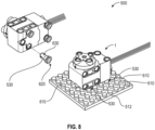
- Fig. 8 illustrates a motor unit 1 according to embodiments of the invention being mounted on a plate shaped construction element 512, of a first type construction element.
- the modular construction system also comprises a connector element 530.
- the connector element 530 is show in a perspective view in the left hand side of Fig. 8 .
- the connector element 530 is configured for connecting construction elements belonging to a first type of construction elements 511 and construction elements, belonging to a second type of construction elements 520 as defined above.
- One or more connector element(s) 530 may further form part of a construction system 500 comprising a motor unit 1 and further comprising one or more first type of construction elements 511 and/or one or more second type of construction elements 520.
- the connector element 530 at one end comprises a cylindrical connecter portions 630 allowing connection to cylindrical connector openings 640 as described above.
- the connector element 530 comprise a knob receiving opening 620 allowing the connector element 530 to connect to a knob 610.
- the knob receiving opening 620 is provided on a cylindrical part of the connector element 530 having a size and shape configured for being connected between four connector knobs 610 of a construction element of the first type 511, such as the plate-shaped first type construction element 512 shown in Fig. 8 .
- the electrical motor unit 1 has cylindrical connector openings 640 and can therefore be connected to a second type construction element 520 having cylindrical connecter portions 630, or to the connector element 530 as shown in Fig. 8 .
- the electrical motor unit 1 is connected to the plate 512 via four connecter elements 530, each of which has a cylindrical connector portion 630 inserted into a cylindrical connector opening 640 on the electrical motor unit 1, and it's oppositely arranged cylindrical part connected between four neighbouring connector knobs 150 on the plate 104.
- the casing 10 of the motor unit 1 - as shown in Figs. 1A-C comprises a plurality of connection means in the form of connector opening 640.
- the casing may alternatively or additionally be provided with other types of connecting means, such as the above mentioned connector knobs 610, knob receiving openings 620, and/or cylindrical connecter portions 630, or in yet other embodiments, connector means suitable for other types of modular construction systems.
- the power outtake power outtake element 20 is connected to the electrical motor 150 via a gearing mechanism provided between the electrical motor 150 and the power outtake element 20.
- a gearing mechanism provided between the electrical motor 150 and the power outtake element 20.
- the motor unit 1 further comprises a rotation sensing mechanism.
- the rotation sensing mechanism is configured for sensing the rotational position of the power outtake element 20 relative to the casing 10.
- the rotation sensing mechanism comprises a disc element 99, such as a permanent magnet.
- the disc element 99 is connected to the power outtake element 20 or to a gear of the gear mechanism, such that the disc element 99 and the power outtake element 20 rotates together, or at least proportionally.
- An exemplary connection between the disc element 99 and the power outtake element 20 will be described in further detail below.
- the disc element 99 is connected to the power outtake element 20 via a first axle 70.
- the rotation sensing mechanism further comprises a sensor device 399 being fixed relative to the casing.
- the sensor device 399 is fixed to a printed circuit board (PCB) 310 forming part of a control subunit 300, which constitutes a control mechanism for the motor unit 1.
- the printed circuit board (PCB) 310 is fixed relative to the casing 10, whereby the sensor device 399 is fixed relative to the casing 10.
- the sensor device 399 is an encoder/rotation sensor, for example an optical sensor capable of registering rotations of the disc element 99 optically, or a magnetic field sensor, when the disc element 99 is a magnet, or an element having magnetic properties.
- the disc element 99 is connected to the power outtake element 20 via a first rotation transfer part 50 being fixedly connected to the disc element 99 and to a receptacle 60 for receiving the first rotation transfer part 50, which receptacle 60 is formed in the power outtake element 20.
- the disc element 99 may be connected to a gear of the gear mechanism via a first rotation transfer part 50 similar to the one shown in the figures. This is not shown in the figures. However, also in this case the first rotation transfer part 50 would be fixedly connected to the disc element 99. The first rotation transfer part 50 would be connected to said gear of the gear mechanism, for example the lowermost gear 220 shown in Figs. 2 , 3 and 5 , via a receptacle 60 for receiving the first rotation transfer part 50, which receptacle 60 would then be formed in the gear of the gear mechanism.
- the receptacle 60 and the first rotation transfer part 50 have cooperating shapes and sizes configured to allow a slight rotation of the power outtake element 20 before the first rotation transfer part 50 is engaged for rotation with the outtake element 20.
- the receptacle 60 may in preferred embodiments and as shown in the figures be provided in the power outtake element 20, and this will be described in further detail in the following. It will however be appreciated that the cooperation between the receptacle 60 and the first rotation transfer part 50 described in the following may also apply to embodiments, where the receptacle 60 is formed in the gear.
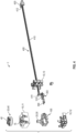
- the casing 10 of the motor unit 1 may as shown in e.g. Fig. 4 comprise three parts a top part 11, a bottom part 12 and an end part 13.
- the parts of the casing 10 protects the internal components (electrical motor 150, gear mechanism, control subunit 300 etc.) from damage, and secures their interrelation/arrangement by forming support for mounting the internal components.
- the three parts 11, 12, 13 allows assembly of the internal components, and may be connected to each other via snap connections, screws or in any other way known in the art.
- the casing 10 may be disassembled to allow maintenance of the motor unit 1, such as replacement of components.
- the parts may be connected such that at least unauthorized disassembly is prevented.
- the casing 10 comprises an opening 15, here shown in the top part 11, which forms a bearing for a portion of the power outtake element 20.
- the opening 15 in the casing has a first diameter.
- the power outtake element 20 is formed by two parts, an inner power outtake element 30 and an outer power outtake element 40.
- the above mentioned first connector 600, 601 is formed in the inner power outtake element 30, and the second connectors 600, 602 are formed in the outer power outtake element 40.
- the inner power outtake element 30 and the outer power outtake element 40 are connected to each other in a rotation preventing way (relative to each other) by an elongate protrusion 47 formed in an inwardly facing/inner surface 46 of the outer power outtake element 40 cooperating with a notch 32' formed as an indentation in the outer surface 32 of a top part 31 of the inner power outtake element 30.
- the inner power outtake element 30, see e.g. Fig 5 , comprises a top part 31 and a bottom part 35.
- the top part 31 is cylindrical and has a second diameter.
- the top part is configured to extend through the opening 15 in the casing 10.
- the diameter of the top part 31, the second dimeter is configured to allow rotation of inner power outtake element 30 relative to the casing 10.
- the bottom part 35 is also cylindrical and has a third diameter, which third diameter is larger than the diameter of the top part 31, such that, when the inner power outtake element 30 is inserted in the opening 15 in the casing 10, an upwardly facing surface of the bottom part 35 may interact with an inwardly facing surface of the casing 10, surround the opening 15, prevents the axial movement of the inner power outtake element 30, in one axial direction.
- the outer power outtake element 40 is connected to the top part 31 of the inner power outtake element 30 on the opposite side of the casing 10 relative to the bottom part 35 of the inner power outtake element 30, as indicated in the exploded view of Fig. 4 .
- the bottom part 35 of the inner power outtake element 30 is arranged on the inner side of the casing 10 while the top part 31 of the inner power outtake element 30 extends through the opening 15 through the casing 10 and the outer power outtake element 40 is connected to the op part 31 of the inner power outtake element 30 on the outside of the casing 10. Thereby, the inner power outtake element 30is prevented from axial movement in the other axial direction.
- the outer power outtake element 40 comprises a body 41, having an upper surface 42 and a lower surface 43, and an outer surface 44.
- An opening 45 is arranged through the body 41 of the outer power outtake element 40 from the upper surface 42 to the lower surface 43, the opening 45 being configured for receiving a portion of the top part 31 of the inner power outtake element 30.
- the opening 45 through the body 41 of the outer power outtake element 40 comprises an inwardly facing surface, inner surface 46.
- a protrusion 47 is formed on and extending inwardly from the inner surface 46 of the outer power outtake element 40.
- the top part 31 of the inner power outtake element 30 comprises an outer end 31' and an inner end 31" and has an outer surface 32, see Fig. 4 .
- the bottom part 35 of the inner power outtake element 30 comprises an outer end and an inner end, and an outer surface 35.
- the outer end of the bottom part 35 connects to the inner end 31" of the top part 31 of the inner power outtake element 30, see e.g. Fig. 4 .
- the top part 31 and the bottom part 35 of the inner power outtake element 30 are formed in one piece as one integrated part.
- an elongate notch 32' is formed as an elongate indentation in the axial direction of the outer surface 32 of the top part of inner power outtake element 30, and configured for cooperating with the protrusion 47 formed on and extending inwardly from the inner surface 46 of the opening 45 through the outer power outtake element 40.
- An inner space 33 is provided in the top part 31 of inner power outtake element 30.
- the inner space 33 has a bottom formed at the inner end 31" of the top part 31 and is open at the outer end 31' of the top part. Thereby the inner space 33 can be considered to be cup -shaped.
- the top part 31 of the inner power outtake element 30 has an inwardly facing surface, inner surface 34, defining the inner space 33, see Fig. 3 .
- the inner space 33 of the top part 31 of the inner power outtake element 30 may constitute the above mentioned second connector 602.
- the cross-section (taken perpendicular to the axial direction of the top part 31 of the inner power outtake element 30) may as described be cross shaped/X-shaped in order to receive a similarly cross shaped/X-shaped axle, such as the axle 524 shown in Fig. 11 .
- the cross shaped cross-section of the inner space 33 may also be appreciated from Fig. 6 showing a section through a power outtake element 20, a receptacle formed 60 therein, a first rotation transfer part 50, and a first axle 70.
- the power outtake element 20 is shown having an inner power outtake element 30 and an outer power outtake element 40.
- Fig. 6 also shows that the inner space 33 of the top part 31 of the inner power outtake element 30 has a bottom surface 34' at the inner end 32" of the top part 31, as may also be appreciated in Fig. 7C .
- An inner space 37 is provided in the cylindrical bottom part top part 35 of inner power outtake element 30.
- This inner space 37 also has a bottom or end wall formed, but formed at the outer end of the bottom part 35 and is open at the inner end of the bottom top part.
- the inner space 37 can be considered to be cup -shaped. Contrary to the inner space 33 of the top part 31, this inner space 37 opens downward and into the inner of the casing 10.
- the bottom part 35 of the inner power outtake element 30 has an inwardly facing surface, inner surface 38, defining the inner space 37, see Fig. 3 .
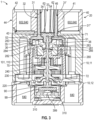
- the inner surface 38 of the bottom part 35 of the inner power outtake element 30 has a cross-sectional shape (taken perpendicular to the axial direction of the cylindrical bottom part 35 of the inner power outtake element 30) allowing cooperation with/connection to an outer surface 284 of a upper part 283 of an outtake disc 280 of the gear mechanism, this outer surface 284 having a cross-sectional shape complementary to the cross-sectional shape of the inner surface 38 of the bottom part 35 of the inner power outtake element 30, see Fig. 2 and 3 .
- the inner power outtake element 30 is in this way driven by the output disc 280 of the gear mechanism.
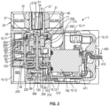
- the electrical motor 150 has a motor output axle 151, see Figs 2 and 5 .
- the motor output axle 151 is connected to a first gear 210, fixed on the motor output axle 151.
- the first gear 210 has an outer surface 211 provided with gear teeth 212, and is configured for cooperating with a second gear 230.
- the second gear 220 is rotationally supported by - but may rotate freely relative to - a first axle 70.
- the second gear 220 comprises a through-going opening 225 (in the axial direction) for this purpose.
- the second gear 220 further comprises a large diameter part 221 and a small diameter part 223.
- the large diameter part 221 comprises gear teeth 222 configured for cooperating with the gear teeth 212 of the first gear 210.
- the output axle 151 of the electrical motor 150 is arranged perpendicular to the rotation axis of the second gear wheel 220.
- the gear teeth 222 on the large diameter part 221 of the second gear wheel 220 is provided on an upwardly facing surface of the large diameter part 221.
- the axes of the gear mechanism and the axis of the output axle 151 from the electrical motor 150 may be arranged in parallel. It will be appreciated that in such embodiment the gear teeth 222 on the large diameter part 221 of the second gear wheel 220 could instead be provided on an outwardly facing surface of the large diameter part 221 (not shown).
- the large diameter part 221 and the small diameter part 223 of the second gear 220 are preferably formed as a single unitary structure.
- the small diameter part 223 of the second gear 220 comprises gear teeth 224 formed on an outer surface thereof and configured for cooperating with a third gear 230 of the gear mechanism.
- the third gear 230 is rotationally supported by - but may rotate freely relative to - a second axle 80.
- the third gear 230 comprises a through-going opening 235 (in the axial direction) for this purpose.
- the second axle 80 is arranged parallel to the first axle 70.
- the third gear 230 further comprises a large diameter part 231 and a small diameter part 233.
- the large diameter part 231 comprises gear teeth 232 formed thereon, and configured for cooperating with the gear teeth 224 formed on the small diameter part 222 of the second gear 220.
- the large diameter part 231 and the small diameter part 233 of the third gear 230 are preferably formed as a single unitary structure.
- the small diameter part 233 of the third gear 230 comprises gear teeth 234 formed on an outer surface thereof, and configured for cooperating with a fourth gear 240 of the gear mechanism.
- the small diameter part 222 of the second gear 220 comprises gear teeth 224 formed on an outer surface thereof and configured for cooperating with a third gear 230 of the gear mechanism.
- the third gear 230 is rotationally supported by - but may rotate freely relative to - a second axle 80.
- the third gear 230 comprises a through-going opening 235 (in the axial direction) for this purpose.
- the second axle 80 is arranged parallel to the first axle 70.
- the third gear 230 further comprises a large diameter part 231 and a small diameter part 233.
- the large diameter part 231 comprises gear teeth 232 formed thereon, and configured for cooperating with the gear teeth 224 formed on the small diameter part 222 of the second gear 220.
- the large diameter part 231 and the small diameter part 233 of the third gear 230 are preferably formed as a single unitary structure.
- the small diameter part 231 of the third gear 230 comprises gear teeth 232 formed on an outer surface thereof, and configured for cooperating with a fourth gear 240 of the gear mechanism.
- the fourth gear 240 is rotationally supported by - but may rotate freely relative to - a first axle 70.
- the fourth gear 240 comprises a through-going opening 245 (in the axial direction) for this purpose.
- the fourth gear 240 further comprises a large diameter part 241 and a small diameter part 243.
- the large diameter part 241 comprises gear teeth 242 formed on an outer surface thereof, and configured for cooperating with the gear teeth 234 formed on the small diameter part 233 of the third gear 230.
- the large diameter part 241 and the small diameter part 243 of the fourth gear 240 are preferably formed as a single unitary structure.
- the small diameter part 243 of the fourth gear 240 comprises gear teeth 244 formed on an outer surface thereof, and configured for cooperating with a fifth gear 250 of the gear mechanism.
- the fifth gear 250 is rotationally supported by - but may rotate freely relative to - the second axle 80.
- the fifth gear 250 comprises a through-going opening 255 (in the axial direction) for this purpose.
- the fifth gear 250 further comprises a large diameter part 251 and a small diameter part 253.
- the large diameter part 251 comprises gear teeth 252 formed on an outer surface thereof, and configured for cooperating with the gear teeth 244 formed on the small diameter part 243 of the fourth gear 240.
- the large diameter part 251 and the small diameter part 253 of the fifth gear 250 are preferably formed as a single unitary structure.
- the small diameter part 253 of the fifth gear 250 comprises gear teeth 254 formed on an outer surface thereof, and configured for cooperating with a sixth gear 260 of the gear mechanism.
- the sixth gear 260 is rotationally supported by - but may rotate freely relative to - the first axle 70.
- the sixth gear 260 comprises a through-going opening 265 (in the axial direction) for this purpose.
- the sixth gear 260 further comprises a lower part 261 and an upper part 263.
- the lower part 261 comprises gear teeth 262 formed on an outer surface thereof, and configured for cooperating with the gear teeth 254 formed on the small diameter part 253 of the fifth gear 250.
- the lower part 261 and the upper part 263 of the sixth gear 260 are preferably formed as a single unitary structure.
- the upper part 263 of the sixth gear 250 is cylindrical and comprises an outer surface 264, which is configured for interacting with an inwardly facing surface 116 of first opening 115 through a portion of the casing 10 in the form of a housing drive subunit housing part 110 (see below).
- the first opening 115 forms a bearing or support for the sixth gear 260 and allows rotation of the sixth gear 260 relative to the casing 10.
- the through-going opening 265 of the sixth gear 260 further has an inwardly facing surface 266, see Fig. 3 , which has a profiled cross-sectional shape (perpendicular to the axial direction of the sixth gear 260), which is configured for cooperating with a similarly profiled outer surface 282 of a lower part 281 of the outtake disc 280, which was mentioned previously.
- the profiled cross-sectional shape inwardly facing surface 266 and the profiled outer surface 282 of a lower part 281 of the outtake disc 280 are complementary such that, when the lower part 281 of the outtake disc 280 is inserted into the through-going opening 265 of the sixth gear 260, the outtake disc 280 and the sixth gear 260 interlock, and thereby rotate together, see Fig. 3 .
- the profiled cross-sectional shape inwardly facing surface 266 and the profiled outer surface 282 of a lower part 281 of the outtake disc 280 are complementary such that that the lower part 281 of the outtake forms a friction fit with at least the upper portion of the through-going opening 265 of the outtake disc 280.
- the outtake disc 280 thus comprises a lower part 281 and an upper part 283.
- the lower part 281 comprises an outer surface, which is profiled.
- the upper part 283 of the outtake disc 280 also comprises an outer surface 284.
- a general diameter of the outer surface 284 of the upper part 283 of the outtake disc 280 is larger than a general outer diameter of the lower part 281 of the outtake disc 280.
- the outer surface of the upper part 283 of the outtake disc 280 is preferably also profiled, and configured for cooperating with the inwardly facing surface, inner surface 38, of the inner space 37 of the bottom part 35 of the inner power outtake element 30.
- the inner surface 38 of the bottom part 35 of the inner power outtake element 30 has a cross-sectional shape (taken perpendicular to the axial direction of the cylindrical bottom part 35 of the inner power outtake element 30) which is complementary with the outer surface 284 of a upper part 283 of the outtake disc 280 of the gear mechanism, in such a way that the outtake disc 280 and the inner power outtake element 30 will rotate together.
- the outtake disc 280 of the gear mechanism has a through-going opening 285 (in the axial direction thereof).
- the through-going opening 285 of the outtake disc 280 is configured for receiving the first axle 70, such that the first axle and the outtake disc 280 are allowed to rotate relative to each other.
- Rotation of the fifth gear 250 will cause a rotation of the sixth gear 260, rotatable relative to the first axle 70, and the casing 10.
- Rotation of the sixth gear 260 will cause a rotation of the outtake disc 280, rotatable relative to the first axle 70, and the casing 10.
- Rotation of the outtake disc 280 will cause a rotation of the inner power outtake element 30, and the outer power outtake element 40 connected thereto. Therefore, rotation induced by the electrical motor 150 will cause the power outtake element 20 to rotate. It is clear that a construction element 520 attached to the power outtake element 20 via the first connector 601 or the second connectors 602 will thereby be rotated.
- parts of the casing 10, including inner structures of the casing 10, may provide bearings and other support for the gears 210, 220, 230, 240, 250, 260, and for the first axle 70 and the second axle 80, and possibly other of the described components or parts thereof
- gear mechanisms may alternatively be used, for example gear mechanisms having a different number of gears and/or other gear ratio, etc.
- the first rotation transfer part 50 comprises body 51 which is essentially cylindrical.
- the body 51 of the first rotation transfer part 51 has an outer surface 52.
- Extending from the cylindrical body 51 of the first rotation transfer part 50 is a first arm 53 and a second arm 54.
- the first arm 53 and the second arm 54 of the first rotation transfer part are located diametrically opposite from each other, and extending from the outer surface 52 of the cylindrical body 51 of the first rotation transfer part 50. In other embodiments only a single arm is provided (not shown).
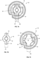
- Fig. 7B also shows that the first and second arms 53, 54 of the first rotation transfer part 50 has a width, first width W1.
- Fig. 6 shows a section through a power outtake element 20 (comprising an inner power outtake element 30 and an outer power outtake element 40), a receptacle 60 formed therein, a first rotation transfer part 50, and a first axle 70.
- the first rotation transfer part 50 comprises an inner space 55 provided in the body 51 of the first rotation transfer part 50.
- the inner space 55 has an inwardly facing surface, inner surface 56, which is configured for cooperating with a first end 71 of the first axle 70.
- the first rotation transfer part 50 may be pinched onto the first end 71 of the first axle 70, such that a rotation of the first rotation transfer part 50 will be transferred to the axle 70.
- the first axle 70 is elongate and comprises a first end 71 and a second end 72 opposite thereto. As shown in Figs. 2 and 3 , the first axle 70 extends from its connection to the first rotation transfer part 50, through the some of the gears 260, 240, 220 of the dear mechanism an towards the PCB 310 with the sensor device 399 provided next to an inner surface of the casing 10 opposite to the first rotation transfer part 50 and opposite to the power outtake element 20.
- a disc element holder 90 may be provided at the second end 72 of the axle 70.
- the disc element holder 90 is attached to the second end 72 of the axle 70, such that a rotation of the axle 70 forces the disc element holder 90 to rotate therewith.
- the disc element holder 90 is configured to receive the disc element 99, such that when the disc element holder 90 rotates, the disc element 99 rotates therewith.
- the first rotation transfer part is received in the receptacle 60.
- the receptacle 60 is provided in the power outtake element 20. More precisely, the receptacle 60 is provided in the inner power outtake element 30 of the power outtake element 20.
- the inner space 33 of the top part 31 of the inner power outtake element 30 has an end surface 34'.
- the inner space 37 of the bottom part 35 of inner power outtake element 30 has and end wall 39.
- a wall separating the top part 31 and the bottom part 35 of the inner power outtake element 30 defines the end surface 34' of the inner space 33 of the top part 31 and the end surface 39 of the inner space 37 of the bottom part 35.
- the receptacle 60 is formed as a through-going hole in the wall separating the top part 31 and the bottom part 35 of the inner power outtake element 30.
- the receptacle extends from the end surface 34' of the inner space 33 of the top part 31 to the end surface 39 of the inner space 37 of the bottom part 35.
- a cross sectional shape (taken perpendicularly to the axial direction of the inner power outtake element 30) of the receptacle 60 corresponds to a cross sectional shape (taken perpendicularly to the axial direction of the first rotation transfer part 50) of the first rotation transfer part 50.
- the receptacle 60 as shown in e.g. the Figs. 6 , 7A, 7C has main trough 61.
- the main trough has an inwardly facing surface 62.
- the main trough 61 of the receptacle 60 is configured to receive the body 51 of the first rotation transfer part 50.
- the body 51 of the first rotation transfer part 50 has a shape corresponding to the trough 61, such that when the first rotation transfer part 50 is rotated, the power outtake element 20 is brought to rotate therewith.
- the shape of the body 51 of the first rotation transfer part 50 can be seen in Fig. 7B .
- the shape of the trough 61 which corresponds to and mates with the shape of the body 51 of the first rotation transfer part 50, can be seen in Fig.7C.
- Fig. 7A shows the body 51 of the first rotation transfer part 50 when connected in the trough 61 of the power outtake element 20.
- a first arm 63 extends outward from the main trough 61 of the receptacle 60. Further a second arm 65 extends outward from the main trough 61 of the receptacle 60. As shown the first arm 63 and the second arm 64 of the receptacle 60 extends out from the main trough 61 of the receptacle 60 on diametrically opposed positions of the main trough 61.
- the first arm 63 of the receptacle 60 is configured to receive the first arm 53 of the first rotation transfer part 50.
- the second arm 66 of the receptacle 60 is configured to receive the second arm 54 of the first rotation transfer part 50.
- Fig. 7C also shows that the first and second arms 63, 64 of the receptacle has a width, second width W2.
- Fig. 7A is can be seen that the first width is slightly larger than the second width W2.
- backlash In mechanical engineering, backlash, sometimes called lash or play, is a clearance or lost motion in a mechanism caused by gaps between parts.
- the first width (W1) is 1-2 mm smaller than the second width (W2).
- a cross sectional shape (taken perpendicularly to the axial direction of the inner power outtake element 30) of the receptacle 60 corresponds to a cross sectional shape (taken perpendicularly to the axial direction of the first rotation transfer part 50) of the first rotation transfer part 50.
- the shapes are the same, but the receptacle 60 is slightly larger than the first rotation transfer part 50.
- Fig. 4 shows an embodiment of the invention where the components of the motor unit 1 has been divided into subunits.
- the casing 10 is shown separated into three parts, the top part e11, the bottom part 12, and an end part 13.
- the electrical motor 150, the disc element 99, and the gear mechanism, e.g. as described above have been enclosed in a drive subunit 100.
- the motor unit 1 may as shown further comprise a control unit 300 comprising at least a printed circuit board 310 on which the sensor device 399 is provided.
- the control unit 300 preferably further comprises control means, such as a processor for handling rotation data received from the sensor device 399.
- the control unit may further comprises control means, such as a processor for controlling the operation of the motor for example based at least partially from the rotation data received from the sensor device 399.
- the operation of the motor unit may further be supplied from an external device operated e.g. by a user. Control signals may be supplied wirelessly.
- control subunit may comprise a wireless receiver.
- the motor unit may further comprise a cord subunit 400.
- the cord subunit 400 comprises a set of cords 410 having a first end 411 connected to the control subunit 300 and a second end connected to an electrical connector plug 420.
- the electrical connector plug 420 allows connection to another device such as controller or an input panel or the like.
- the cord subunit may transfer data to and from the control subunit 300 of the motor unit 1.
- the cord subunit 400 may transfer electrical energy to and from a unit comprising a battery.
- the motor unit 1 may alternatively or additionally comprise a battery for powering the electrical motor 150 and the control unit 300.
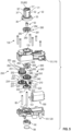
- Fig. 5 shows the drive subunit 100 of the motor unit 1 of Fig. 4 in a detailed exploded view.
- the drive subunit 100 comprises a housing 101.
- the housing 101 is formed by a top part 110 and a bottom part 120.
- An opening 115 is provided in the top part 110 of the housing 101 of the drive subunit 100.
- a not shown opening is provided in the bottom part 120 of the housing 101 of the drive subunit 100, this opening being shaped and sized to allow the sensor device 399 to be located next to a bottom surface of the disc element 99.
- the electrical motor 150, the gear mechanism etc. is provided inside the housing 101 of the drive subunit 100.
- the top part and the bottom part 110, 120 may be assembled by the use of screws indicated by 130 in Fig. 5 .
- the casing 10, the housing 101, the gears, and the power outtake element 20 are preferably moulded in plastic in an injection moulding process.
Landscapes
- Engineering & Computer Science (AREA)
- Power Engineering (AREA)
- Microelectronics & Electronic Packaging (AREA)
- Connection Of Motors, Electrical Generators, Mechanical Devices, And The Like (AREA)
- Toys (AREA)
Applications Claiming Priority (2)
| Application Number | Priority Date | Filing Date | Title |
|---|---|---|---|
| DKPA202170133A DK181187B1 (en) | 2021-03-25 | 2021-03-25 | Modular construction system motor unit for modular construction system |
| PCT/EP2022/057796 WO2022200513A1 (en) | 2021-03-25 | 2022-03-24 | Modular construction system motor unit |
Publications (2)
| Publication Number | Publication Date |
|---|---|
| EP4313341A1 EP4313341A1 (en) | 2024-02-07 |
| EP4313341B1 true EP4313341B1 (en) | 2024-12-18 |
Family
ID=81384693
Family Applications (1)
| Application Number | Title | Priority Date | Filing Date |
|---|---|---|---|
| EP22718149.2A Active EP4313341B1 (en) | 2021-03-25 | 2022-03-24 | Modular construction system motor unit |
Country Status (10)
| Country | Link |
|---|---|
| US (1) | US12494694B2 (cg-RX-API-DMAC10.html) |
| EP (1) | EP4313341B1 (cg-RX-API-DMAC10.html) |
| JP (1) | JP7870292B2 (cg-RX-API-DMAC10.html) |
| KR (1) | KR20230160871A (cg-RX-API-DMAC10.html) |
| CN (1) | CN115133708A (cg-RX-API-DMAC10.html) |
| BR (1) | BR112023019306A2 (cg-RX-API-DMAC10.html) |
| DK (1) | DK181187B1 (cg-RX-API-DMAC10.html) |
| IL (1) | IL307156B1 (cg-RX-API-DMAC10.html) |
| MX (1) | MX2023011224A (cg-RX-API-DMAC10.html) |
| WO (1) | WO2022200513A1 (cg-RX-API-DMAC10.html) |
Families Citing this family (2)
| Publication number | Priority date | Publication date | Assignee | Title |
|---|---|---|---|---|
| USD1139687S1 (en) * | 2024-10-07 | 2026-08-04 | Lego A/S | Color sensor toy brick |
| USD1139688S1 (en) * | 2024-10-07 | 2026-08-04 | Lego A/S | Single motor toy brick |
Family Cites Families (31)
| Publication number | Priority date | Publication date | Assignee | Title |
|---|---|---|---|---|
| JPH0691062A (ja) | 1992-09-16 | 1994-04-05 | Sankyo Seiki Mfg Co Ltd | ブロック玩具用ブロック・ユニット |
| US5687610A (en) * | 1993-09-22 | 1997-11-18 | Interlego Ag | Toy gearbox and a claw clutch therefor |
| US5638499A (en) | 1994-05-27 | 1997-06-10 | O'connor; Michael | Image composition method and apparatus for developing, storing and reproducing image data using absorption, reflection and transmission properties of images to be combined |
| CA2176073A1 (en) | 1995-06-26 | 1996-12-27 | Henry Hung Lai Chung | Construction toy support base |
| DE19543284A1 (de) | 1995-11-21 | 1997-05-22 | Robbe Modellsport Gmbh & Co Kg | Antriebseinheit für ein Modellflugzeug |
| US20020190984A1 (en) | 1999-10-01 | 2002-12-19 | Larry D. Seiler | Voxel and sample pruning in a parallel pipelined volume rendering system |
| US7012604B1 (en) | 2002-09-12 | 2006-03-14 | Advanced Micro Devices, Inc. | System architecture for high speed ray tracing |
| US7596473B2 (en) | 2003-05-20 | 2009-09-29 | Interlego Ag | Method of constructing a virtual construction model |
| US7480597B2 (en) | 2003-05-20 | 2009-01-20 | Lego A/S | Method, system and storage medium for generating virtual brick models |
| RU2007101498A (ru) | 2004-06-17 | 2008-07-27 | Лего А/С (Dk) | Автоматическое генерирование инструкций для построения моделей из стандартных блоков |
| US7884819B2 (en) | 2006-09-27 | 2011-02-08 | International Business Machines Corporation | Pixel color accumulation in a ray tracing image processing system |
| JP2008206671A (ja) | 2007-02-26 | 2008-09-11 | Taya Engineering Kk | ラジコン模型のサーボモータ中立位置設定装置 |
| US7979251B2 (en) | 2007-03-16 | 2011-07-12 | Lego A/S | Automatic generation of building instructions for building element models |
| MX2010003848A (es) * | 2007-10-11 | 2010-08-04 | Lego As | Sistema de construccion de un juguete. |
| KR101475779B1 (ko) | 2008-06-02 | 2014-12-23 | 삼성전자주식회사 | 3d 영상 처리 방법 |
| US8525826B2 (en) | 2008-08-08 | 2013-09-03 | International Business Machines Corporation | System for iterative interactive ray tracing in a multiprocessor environment |
| US9230360B2 (en) | 2009-10-02 | 2016-01-05 | Lego A/S | Connectivity depended geometry optimization for real-time rendering |
| KR101854707B1 (ko) | 2010-11-15 | 2018-05-04 | 인튜어티브 서지컬 오퍼레이션즈 인코포레이티드 | 수술 기구에서 기구 샤프트 감김과 단부 작동기 작동의 해제 |
| JP2012200491A (ja) | 2011-03-28 | 2012-10-22 | Yamazaki:Kk | ギアボックスユニット |
| JP5839907B2 (ja) | 2011-09-15 | 2016-01-06 | キヤノン株式会社 | 画像処理装置および画像処理方法 |
| GB201207460D0 (en) | 2012-04-30 | 2012-06-13 | Univ Greenwich | A servomechanism |
| US20150245593A1 (en) | 2014-03-03 | 2015-09-03 | Jason E. O'mara | Autonomous motion device, system, and method |
| DE102014222644A1 (de) | 2014-11-06 | 2016-05-12 | Schaeffler Technologies AG & Co. KG | Hybridmodul für ein Kraftfahrzeug |
| EP3419730B1 (en) | 2016-02-24 | 2020-08-05 | Danmarks Tekniske Universitet | A set of robotic building elements |
| EP3589380B1 (en) | 2017-03-03 | 2021-05-05 | Lego A/S | An interactive modular construction element and a modular construction system with interactive modular construction elements |
| JP6481002B1 (ja) | 2017-10-02 | 2019-03-13 | 株式会社バンダイ | 移動玩具、移動玩具用動作ユニット、及び移動玩具セット |
| JP2019182281A (ja) | 2018-04-13 | 2019-10-24 | 株式会社村田製作所 | 羽体およびそれを用いた羽ばたき装置 |
| KR101954824B1 (ko) | 2018-07-31 | 2019-03-06 | 목포대학교산학협력단 | 비계용 연결브라켓 최종강도 시험장치 및 시험방법 |
| WO2020121189A1 (en) | 2018-12-14 | 2020-06-18 | Building Blocks Learning Solutions Pvt. Ltd | Modular robotic system and methods for configuring robotic module |
| US12121827B2 (en) * | 2019-01-31 | 2024-10-22 | Lego A/S | Toy construction system with interactive function construction elements |
| KR102384304B1 (ko) | 2019-07-15 | 2022-04-07 | 레고 에이/에스 | 렌더링 방법 및 이를 수행하는 렌더링 장치 |
-
2021
- 2021-03-25 DK DKPA202170133A patent/DK181187B1/en active IP Right Grant
- 2021-06-24 CN CN202110702346.6A patent/CN115133708A/zh active Pending
-
2022
- 2022-03-24 EP EP22718149.2A patent/EP4313341B1/en active Active
- 2022-03-24 JP JP2023558808A patent/JP7870292B2/ja active Active
- 2022-03-24 MX MX2023011224A patent/MX2023011224A/es unknown
- 2022-03-24 IL IL307156A patent/IL307156B1/en unknown
- 2022-03-24 WO PCT/EP2022/057796 patent/WO2022200513A1/en not_active Ceased
- 2022-03-24 BR BR112023019306A patent/BR112023019306A2/pt unknown
- 2022-03-24 KR KR1020237036097A patent/KR20230160871A/ko active Pending
- 2022-03-24 US US18/551,998 patent/US12494694B2/en active Active
Also Published As
| Publication number | Publication date |
|---|---|
| IL307156B1 (en) | 2026-08-01 |
| JP7870292B2 (ja) | 2026-06-04 |
| DK202170133A1 (en) | 2022-10-05 |
| EP4313341A1 (en) | 2024-02-07 |
| KR20230160871A (ko) | 2023-11-24 |
| MX2023011224A (es) | 2023-10-20 |
| WO2022200513A1 (en) | 2022-09-29 |
| DK181187B1 (en) | 2023-04-13 |
| JP2024511627A (ja) | 2024-03-14 |
| CN115133708A (zh) | 2022-09-30 |
| BR112023019306A2 (pt) | 2023-10-31 |
| US20240171041A1 (en) | 2024-05-23 |
| US12494694B2 (en) | 2025-12-09 |
| IL307156A (en) | 2023-11-01 |
Similar Documents
| Publication | Publication Date | Title |
|---|---|---|
| US12494694B2 (en) | Modular construction system motor unit | |
| US9581220B2 (en) | Separable actuator | |
| US11796045B2 (en) | Strain wave gear with encoder integration | |
| EP1253700B1 (en) | Motor having rotatable shaft coupled with worm shaft | |
| EP1287869A2 (en) | Robotic toy modular system | |
| CN104039406B (zh) | 模块式运动学构造套件 | |
| JP5788428B2 (ja) | リニアアクチュエータ | |
| KR101622365B1 (ko) | 모듈형 교구재 로봇 | |
| WO2013173269A2 (en) | Actuator | |
| HK40077167A (en) | Modular construction system motor unit | |
| EP3419730B1 (en) | A set of robotic building elements | |
| JP6562794B2 (ja) | アクチュエータ | |
| KR101207853B1 (ko) | 다양한 관절 형태에 적응가능한 액츄에이터 모듈 및 이를 이용한 관절 구조체 | |
| US11491415B2 (en) | Connector for constructions system and construction system | |
| JP5484190B2 (ja) | ギヤードモータおよびその製造方法 | |
| KR101796917B1 (ko) | 액추에이터 모듈의 아이들러 혼 착탈 장치 | |
| CN214404609U (zh) | 一种齿轮箱及致动器 | |
| JP3771180B2 (ja) | ブラシ装置の支持構造 | |
| US20190203706A1 (en) | Pump device | |
| JP2015155759A (ja) | リニアアクチュエータ | |
| JP2003018794A (ja) | モータ | |
| JP5061279B2 (ja) | ユニバーサルコネクタ機構 | |
| JP7473949B2 (ja) | 面状搬送装置 | |
| JP2001028863A (ja) | モータ | |
| CN105308791B (zh) | 模块化调节装置 |
Legal Events
| Date | Code | Title | Description |
|---|---|---|---|
| STAA | Information on the status of an ep patent application or granted ep patent |
Free format text: STATUS: UNKNOWN |
|
| STAA | Information on the status of an ep patent application or granted ep patent |
Free format text: STATUS: THE INTERNATIONAL PUBLICATION HAS BEEN MADE |
|
| PUAI | Public reference made under article 153(3) epc to a published international application that has entered the european phase |
Free format text: ORIGINAL CODE: 0009012 |
|
| STAA | Information on the status of an ep patent application or granted ep patent |
Free format text: STATUS: REQUEST FOR EXAMINATION WAS MADE |
|
| 17P | Request for examination filed |
Effective date: 20231004 |
|
| AK | Designated contracting states |
Kind code of ref document: A1 Designated state(s): AL AT BE BG CH CY CZ DE DK EE ES FI FR GB GR HR HU IE IS IT LI LT LU LV MC MK MT NL NO PL PT RO RS SE SI SK SM TR |
|
| P01 | Opt-out of the competence of the unified patent court (upc) registered |
Effective date: 20240312 |
|
| DAV | Request for validation of the european patent (deleted) | ||
| DAX | Request for extension of the european patent (deleted) | ||
| GRAP | Despatch of communication of intention to grant a patent |
Free format text: ORIGINAL CODE: EPIDOSNIGR1 |
|
| STAA | Information on the status of an ep patent application or granted ep patent |
Free format text: STATUS: GRANT OF PATENT IS INTENDED |
|
| INTG | Intention to grant announced |
Effective date: 20240709 |
|
| GRAS | Grant fee paid |
Free format text: ORIGINAL CODE: EPIDOSNIGR3 |
|
| GRAA | (expected) grant |
Free format text: ORIGINAL CODE: 0009210 |
|
| STAA | Information on the status of an ep patent application or granted ep patent |
Free format text: STATUS: THE PATENT HAS BEEN GRANTED |
|
| AK | Designated contracting states |
Kind code of ref document: B1 Designated state(s): AL AT BE BG CH CY CZ DE DK EE ES FI FR GB GR HR HU IE IS IT LI LT LU LV MC MK MT NL NO PL PT RO RS SE SI SK SM TR |
|
| REG | Reference to a national code |
Ref country code: CH Ref legal event code: EP |
|
| REG | Reference to a national code |
Ref country code: DE Ref legal event code: R096 Ref document number: 602022008884 Country of ref document: DE |
|
| REG | Reference to a national code |
Ref country code: IE Ref legal event code: FG4D |
|
| REG | Reference to a national code |
Ref country code: LT Ref legal event code: MG9D |
|
| PG25 | Lapsed in a contracting state [announced via postgrant information from national office to epo] |
Ref country code: HR Free format text: LAPSE BECAUSE OF FAILURE TO SUBMIT A TRANSLATION OF THE DESCRIPTION OR TO PAY THE FEE WITHIN THE PRESCRIBED TIME-LIMIT Effective date: 20241218 |
|
| PG25 | Lapsed in a contracting state [announced via postgrant information from national office to epo] |
Ref country code: FI Free format text: LAPSE BECAUSE OF FAILURE TO SUBMIT A TRANSLATION OF THE DESCRIPTION OR TO PAY THE FEE WITHIN THE PRESCRIBED TIME-LIMIT Effective date: 20241218 |
|
| PG25 | Lapsed in a contracting state [announced via postgrant information from national office to epo] |
Ref country code: BG Free format text: LAPSE BECAUSE OF FAILURE TO SUBMIT A TRANSLATION OF THE DESCRIPTION OR TO PAY THE FEE WITHIN THE PRESCRIBED TIME-LIMIT Effective date: 20241218 |
|
| PG25 | Lapsed in a contracting state [announced via postgrant information from national office to epo] |
Ref country code: NO Free format text: LAPSE BECAUSE OF FAILURE TO SUBMIT A TRANSLATION OF THE DESCRIPTION OR TO PAY THE FEE WITHIN THE PRESCRIBED TIME-LIMIT Effective date: 20250318 |
|
| REG | Reference to a national code |
Ref country code: NL Ref legal event code: MP Effective date: 20241218 |
|
| PG25 | Lapsed in a contracting state [announced via postgrant information from national office to epo] |
Ref country code: GR Free format text: LAPSE BECAUSE OF FAILURE TO SUBMIT A TRANSLATION OF THE DESCRIPTION OR TO PAY THE FEE WITHIN THE PRESCRIBED TIME-LIMIT Effective date: 20250319 Ref country code: LV Free format text: LAPSE BECAUSE OF FAILURE TO SUBMIT A TRANSLATION OF THE DESCRIPTION OR TO PAY THE FEE WITHIN THE PRESCRIBED TIME-LIMIT Effective date: 20241218 |
|
| PG25 | Lapsed in a contracting state [announced via postgrant information from national office to epo] |
Ref country code: RS Free format text: LAPSE BECAUSE OF FAILURE TO SUBMIT A TRANSLATION OF THE DESCRIPTION OR TO PAY THE FEE WITHIN THE PRESCRIBED TIME-LIMIT Effective date: 20250318 |
|
| PG25 | Lapsed in a contracting state [announced via postgrant information from national office to epo] |
Ref country code: NL Free format text: LAPSE BECAUSE OF FAILURE TO SUBMIT A TRANSLATION OF THE DESCRIPTION OR TO PAY THE FEE WITHIN THE PRESCRIBED TIME-LIMIT Effective date: 20241218 |
|
| REG | Reference to a national code |
Ref country code: AT Ref legal event code: MK05 Ref document number: 1751802 Country of ref document: AT Kind code of ref document: T Effective date: 20241218 |
|
| PG25 | Lapsed in a contracting state [announced via postgrant information from national office to epo] |
Ref country code: SM Free format text: LAPSE BECAUSE OF FAILURE TO SUBMIT A TRANSLATION OF THE DESCRIPTION OR TO PAY THE FEE WITHIN THE PRESCRIBED TIME-LIMIT Effective date: 20241218 |
|
| PG25 | Lapsed in a contracting state [announced via postgrant information from national office to epo] |
Ref country code: PL Free format text: LAPSE BECAUSE OF FAILURE TO SUBMIT A TRANSLATION OF THE DESCRIPTION OR TO PAY THE FEE WITHIN THE PRESCRIBED TIME-LIMIT Effective date: 20241218 |
|
| PG25 | Lapsed in a contracting state [announced via postgrant information from national office to epo] |
Ref country code: ES Free format text: LAPSE BECAUSE OF FAILURE TO SUBMIT A TRANSLATION OF THE DESCRIPTION OR TO PAY THE FEE WITHIN THE PRESCRIBED TIME-LIMIT Effective date: 20241218 |
|
| PG25 | Lapsed in a contracting state [announced via postgrant information from national office to epo] |
Ref country code: IS Free format text: LAPSE BECAUSE OF FAILURE TO SUBMIT A TRANSLATION OF THE DESCRIPTION OR TO PAY THE FEE WITHIN THE PRESCRIBED TIME-LIMIT Effective date: 20250418 |
|
| PG25 | Lapsed in a contracting state [announced via postgrant information from national office to epo] |
Ref country code: PT Free format text: LAPSE BECAUSE OF FAILURE TO SUBMIT A TRANSLATION OF THE DESCRIPTION OR TO PAY THE FEE WITHIN THE PRESCRIBED TIME-LIMIT Effective date: 20250421 |
|
| PG25 | Lapsed in a contracting state [announced via postgrant information from national office to epo] |
Ref country code: EE Free format text: LAPSE BECAUSE OF FAILURE TO SUBMIT A TRANSLATION OF THE DESCRIPTION OR TO PAY THE FEE WITHIN THE PRESCRIBED TIME-LIMIT Effective date: 20241218 |
|
| PG25 | Lapsed in a contracting state [announced via postgrant information from national office to epo] |
Ref country code: RO Free format text: LAPSE BECAUSE OF FAILURE TO SUBMIT A TRANSLATION OF THE DESCRIPTION OR TO PAY THE FEE WITHIN THE PRESCRIBED TIME-LIMIT Effective date: 20241218 Ref country code: AT Free format text: LAPSE BECAUSE OF FAILURE TO SUBMIT A TRANSLATION OF THE DESCRIPTION OR TO PAY THE FEE WITHIN THE PRESCRIBED TIME-LIMIT Effective date: 20241218 |
|
| PG25 | Lapsed in a contracting state [announced via postgrant information from national office to epo] |
Ref country code: SK Free format text: LAPSE BECAUSE OF FAILURE TO SUBMIT A TRANSLATION OF THE DESCRIPTION OR TO PAY THE FEE WITHIN THE PRESCRIBED TIME-LIMIT Effective date: 20241218 |
|
| PG25 | Lapsed in a contracting state [announced via postgrant information from national office to epo] |
Ref country code: CZ Free format text: LAPSE BECAUSE OF FAILURE TO SUBMIT A TRANSLATION OF THE DESCRIPTION OR TO PAY THE FEE WITHIN THE PRESCRIBED TIME-LIMIT Effective date: 20241218 |
|
| PG25 | Lapsed in a contracting state [announced via postgrant information from national office to epo] |
Ref country code: IT Free format text: LAPSE BECAUSE OF FAILURE TO SUBMIT A TRANSLATION OF THE DESCRIPTION OR TO PAY THE FEE WITHIN THE PRESCRIBED TIME-LIMIT Effective date: 20241218 |
|
| PG25 | Lapsed in a contracting state [announced via postgrant information from national office to epo] |
Ref country code: SE Free format text: LAPSE BECAUSE OF FAILURE TO SUBMIT A TRANSLATION OF THE DESCRIPTION OR TO PAY THE FEE WITHIN THE PRESCRIBED TIME-LIMIT Effective date: 20241218 |
|
| REG | Reference to a national code |
Ref country code: DE Ref legal event code: R097 Ref document number: 602022008884 Country of ref document: DE |
|
| PG25 | Lapsed in a contracting state [announced via postgrant information from national office to epo] |
Ref country code: DK Free format text: LAPSE BECAUSE OF FAILURE TO SUBMIT A TRANSLATION OF THE DESCRIPTION OR TO PAY THE FEE WITHIN THE PRESCRIBED TIME-LIMIT Effective date: 20241218 |
|
| PG25 | Lapsed in a contracting state [announced via postgrant information from national office to epo] |
Ref country code: MC Free format text: LAPSE BECAUSE OF FAILURE TO SUBMIT A TRANSLATION OF THE DESCRIPTION OR TO PAY THE FEE WITHIN THE PRESCRIBED TIME-LIMIT Effective date: 20241218 |
|
| REG | Reference to a national code |
Ref country code: CH Ref legal event code: H13 Free format text: ST27 STATUS EVENT CODE: U-0-0-H10-H13 (AS PROVIDED BY THE NATIONAL OFFICE) Effective date: 20251023 |
|
| PLBE | No opposition filed within time limit |
Free format text: ORIGINAL CODE: 0009261 |
|
| STAA | Information on the status of an ep patent application or granted ep patent |
Free format text: STATUS: NO OPPOSITION FILED WITHIN TIME LIMIT |
|
| PG25 | Lapsed in a contracting state [announced via postgrant information from national office to epo] |
Ref country code: LU Free format text: LAPSE BECAUSE OF NON-PAYMENT OF DUE FEES Effective date: 20250324 |
|
| 26N | No opposition filed |
Effective date: 20250919 |
|
| REG | Reference to a national code |
Ref country code: BE Ref legal event code: MM Effective date: 20250331 |
|
| PG25 | Lapsed in a contracting state [announced via postgrant information from national office to epo] |
Ref country code: FR Free format text: LAPSE BECAUSE OF NON-PAYMENT OF DUE FEES Effective date: 20250331 |
|
| PG25 | Lapsed in a contracting state [announced via postgrant information from national office to epo] |
Ref country code: BE Free format text: LAPSE BECAUSE OF NON-PAYMENT OF DUE FEES Effective date: 20250331 |
|
| PG25 | Lapsed in a contracting state [announced via postgrant information from national office to epo] |
Ref country code: CH Free format text: LAPSE BECAUSE OF NON-PAYMENT OF DUE FEES Effective date: 20250331 |
|
| PG25 | Lapsed in a contracting state [announced via postgrant information from national office to epo] |
Ref country code: IE Free format text: LAPSE BECAUSE OF NON-PAYMENT OF DUE FEES Effective date: 20250324 |
|
| PGFP | Annual fee paid to national office [announced via postgrant information from national office to epo] |
Ref country code: GB Payment date: 20260324 Year of fee payment: 5 |
|
| PGFP | Annual fee paid to national office [announced via postgrant information from national office to epo] |
Ref country code: DE Payment date: 20260319 Year of fee payment: 5 |
|
| PG25 | Lapsed in a contracting state [announced via postgrant information from national office to epo] |
Ref country code: CY Free format text: LAPSE BECAUSE OF FAILURE TO SUBMIT A TRANSLATION OF THE DESCRIPTION OR TO PAY THE FEE WITHIN THE PRESCRIBED TIME-LIMIT Effective date: 20241218 |
|
| PG25 | Lapsed in a contracting state [announced via postgrant information from national office to epo] |
Ref country code: LT Free format text: LAPSE BECAUSE OF FAILURE TO SUBMIT A TRANSLATION OF THE DESCRIPTION OR TO PAY THE FEE WITHIN THE PRESCRIBED TIME-LIMIT Effective date: 20241218 |
|
| PG25 | Lapsed in a contracting state [announced via postgrant information from national office to epo] |
Ref country code: TR Free format text: LAPSE BECAUSE OF FAILURE TO SUBMIT A TRANSLATION OF THE DESCRIPTION OR TO PAY THE FEE WITHIN THE PRESCRIBED TIME-LIMIT Effective date: 20241218 |