EP4311949A1 - Dispositif de verrouillage d'ensemble, boulon de connexion en combinaison avec le dispositif de verrouillage d'ensemble, composant avec un boulon de connexion préinstallé au moyen du dispositif de verrouillage d'ensemble ainsi qu'un procédé de fabrication pour le dispositif de verrouillage d'ensemble et un procédé d'assemblage d'un boulon de connexion avec le dispositif de verrouillage d'ensemble dans une ouverture de composant - Google Patents
Dispositif de verrouillage d'ensemble, boulon de connexion en combinaison avec le dispositif de verrouillage d'ensemble, composant avec un boulon de connexion préinstallé au moyen du dispositif de verrouillage d'ensemble ainsi qu'un procédé de fabrication pour le dispositif de verrouillage d'ensemble et un procédé d'assemblage d'un boulon de connexion avec le dispositif de verrouillage d'ensemble dans une ouverture de composant Download PDFInfo
- Publication number
- EP4311949A1 EP4311949A1 EP22306132.6A EP22306132A EP4311949A1 EP 4311949 A1 EP4311949 A1 EP 4311949A1 EP 22306132 A EP22306132 A EP 22306132A EP 4311949 A1 EP4311949 A1 EP 4311949A1
- Authority
- EP
- European Patent Office
- Prior art keywords
- component
- locking device
- thread
- bolt
- assembly locking
- Prior art date
- Legal status (The legal status is an assumption and is not a legal conclusion. Google has not performed a legal analysis and makes no representation as to the accuracy of the status listed.)
- Pending
Links
- 238000000034 method Methods 0.000 title claims description 40
- 238000004519 manufacturing process Methods 0.000 title claims description 7
- 230000007704 transition Effects 0.000 claims description 39
- 238000004804 winding Methods 0.000 claims description 10
- 230000000717 retained effect Effects 0.000 claims description 6
- 239000011295 pitch Substances 0.000 description 18
- 238000010276 construction Methods 0.000 description 11
- 238000009434 installation Methods 0.000 description 6
- 230000007423 decrease Effects 0.000 description 5
- 230000006870 function Effects 0.000 description 3
- 238000003780 insertion Methods 0.000 description 3
- 230000037431 insertion Effects 0.000 description 3
- 239000013013 elastic material Substances 0.000 description 2
- 239000000463 material Substances 0.000 description 2
- 239000002184 metal Substances 0.000 description 2
- QNRATNLHPGXHMA-XZHTYLCXSA-N (r)-(6-ethoxyquinolin-4-yl)-[(2s,4s,5r)-5-ethyl-1-azabicyclo[2.2.2]octan-2-yl]methanol;hydrochloride Chemical compound Cl.C([C@H]([C@H](C1)CC)C2)CN1[C@@H]2[C@H](O)C1=CC=NC2=CC=C(OCC)C=C21 QNRATNLHPGXHMA-XZHTYLCXSA-N 0.000 description 1
- 239000008186 active pharmaceutical agent Substances 0.000 description 1
- 238000004873 anchoring Methods 0.000 description 1
- 238000005520 cutting process Methods 0.000 description 1
- 230000003247 decreasing effect Effects 0.000 description 1
- 230000001419 dependent effect Effects 0.000 description 1
- 238000011161 development Methods 0.000 description 1
- 230000018109 developmental process Effects 0.000 description 1
- 238000006073 displacement reaction Methods 0.000 description 1
- 230000000694 effects Effects 0.000 description 1
- 230000005489 elastic deformation Effects 0.000 description 1
- 230000008571 general function Effects 0.000 description 1
- 230000014759 maintenance of location Effects 0.000 description 1
- 238000012546 transfer Methods 0.000 description 1
Images


Classifications
-
- F—MECHANICAL ENGINEERING; LIGHTING; HEATING; WEAPONS; BLASTING
- F16—ENGINEERING ELEMENTS AND UNITS; GENERAL MEASURES FOR PRODUCING AND MAINTAINING EFFECTIVE FUNCTIONING OF MACHINES OR INSTALLATIONS; THERMAL INSULATION IN GENERAL
- F16B—DEVICES FOR FASTENING OR SECURING CONSTRUCTIONAL ELEMENTS OR MACHINE PARTS TOGETHER, e.g. NAILS, BOLTS, CIRCLIPS, CLAMPS, CLIPS OR WEDGES; JOINTS OR JOINTING
- F16B41/00—Measures against loss of bolts, nuts, or pins; Measures against unauthorised operation of bolts, nuts or pins
- F16B41/002—Measures against loss of bolts, nuts or pins
-
- F—MECHANICAL ENGINEERING; LIGHTING; HEATING; WEAPONS; BLASTING
- F16—ENGINEERING ELEMENTS AND UNITS; GENERAL MEASURES FOR PRODUCING AND MAINTAINING EFFECTIVE FUNCTIONING OF MACHINES OR INSTALLATIONS; THERMAL INSULATION IN GENERAL
- F16B—DEVICES FOR FASTENING OR SECURING CONSTRUCTIONAL ELEMENTS OR MACHINE PARTS TOGETHER, e.g. NAILS, BOLTS, CIRCLIPS, CLAMPS, CLIPS OR WEDGES; JOINTS OR JOINTING
- F16B2/00—Friction-grip releasable fastenings
- F16B2/20—Clips, i.e. with gripping action effected solely by the inherent resistance to deformation of the material of the fastening
- F16B2/22—Clips, i.e. with gripping action effected solely by the inherent resistance to deformation of the material of the fastening of resilient material, e.g. rubbery material
- F16B2/24—Clips, i.e. with gripping action effected solely by the inherent resistance to deformation of the material of the fastening of resilient material, e.g. rubbery material of metal
- F16B2/248—Clips, i.e. with gripping action effected solely by the inherent resistance to deformation of the material of the fastening of resilient material, e.g. rubbery material of metal of wire
-
- F—MECHANICAL ENGINEERING; LIGHTING; HEATING; WEAPONS; BLASTING
- F16—ENGINEERING ELEMENTS AND UNITS; GENERAL MEASURES FOR PRODUCING AND MAINTAINING EFFECTIVE FUNCTIONING OF MACHINES OR INSTALLATIONS; THERMAL INSULATION IN GENERAL
- F16B—DEVICES FOR FASTENING OR SECURING CONSTRUCTIONAL ELEMENTS OR MACHINE PARTS TOGETHER, e.g. NAILS, BOLTS, CIRCLIPS, CLAMPS, CLIPS OR WEDGES; JOINTS OR JOINTING
- F16B5/00—Joining sheets or plates, e.g. panels, to one another or to strips or bars parallel to them
- F16B5/02—Joining sheets or plates, e.g. panels, to one another or to strips or bars parallel to them by means of fastening members using screw-thread
- F16B5/0208—Joining sheets or plates, e.g. panels, to one another or to strips or bars parallel to them by means of fastening members using screw-thread using panel fasteners, i.e. permanent attachments allowing for quick assembly
Definitions
- the present invention relates to an assembly locking device for pre-installing a connecting bolt in a component opening. Furthermore, a connecting bolt in combination with the assembly locking device is provided to be pre-installed in a component opening facilitating a subsequent connecting with a further component. Additionally, a component with a pre-installed connecting bolt by means of the assembly locking device as well as a manufacturing method for the assembly locking device and an assembly method of a connecting bolt with the assembly locking device within a component opening are provided.
- an assembly locking device according to independent claim 1, a thread bolt in combination with the assembly locking device according to claims 10 and 11, a component with a pre-installed connecting bolt by means of the assembly locking device according to independent claim 17 as well as a component with a pre-installed connecting bolt by means of the assembly locking device in combination with an outer threaded bushing according to independent claim 18, a manufacturing method for the assembly locking device according to claim 19, an assembly method of a connecting bolt with the assembly locking device within a component opening according to independent claim 20 and 21, and an assembly method of a connecting bolt with the assembly locking device in combination with an outer threaded bushing according to claim 24, as well as a connecting method for a first and a second component according to independent claims 25 and 26.
- the present invention provides an assembly locking device adapted to a shaft of a connecting bolt, preferably a thread bolt, with a bolt head so that the assembly locking device is positionable on the shaft in a loss-proof manner and the connecting bolt is arrangeable in a pull-out-proof manner inserted into a component opening with the help of the assembly locking device.
- the assembly locking device includes the following features: a wire coil comprised of a plurality of helically wound turns, the coil having a first end and a second end, starting at the first end of the wire coil, a holding turn is provided which extends over an angular range of at least 360° about a central longitudinal axis of the wire coil and comprises an inner diameter D H , following the holding turn, a clamping coil portion is arranged that is formed like a truncated cone having a plurality of subsequent turns of an increasing inner diameter D K compared with the holding turn, with the clamping coil portion extending over at least two turns about the central longitudinal axis of the wire coil and comprises a pitch P W that is larger compared with the holding turn, and following the clamping coil portion and at the second end of the wire coil, a positioning turn is provided, extending over an angular range of at least 270° about the central longitudinal axis of the wire coil, having an inner diameter D P for which D K >D P ⁇ D H applies, and having a
- the inventive assembly locking device is based on a simple and inexpensive wire construction. It serves for pre-positioning or pre-installation of a connecting bolt within a component opening to facilitate a subsequent connection process of the first component to a second component.
- the assembly locking device is preferably combined with a bolt-like connecting element having a bolt head and a bolt shaft with a connecting structure.
- a connecting structure is preferably formed by a thread, a clamping or snapping structure, a riveting structure or the like.
- the wire construction of the assembly locking device serves for holding the connecting bolt, preferably a thread bolt, in position for fastening at the second component.
- a helically wound wire structure includes at a first end the holding turn adapted to hold the shaft of the thread bolt or to be hold on that shaft.
- a positioning turn is provided at a second end of the helically wound wire coil.
- the holding turn and the positioning turn are preferably coaxially aligned with respect to a longitudinal center axis of the assembly locking device.
- the clamping coil is arranged to retain the assembly locking device in a component opening.
- the clamping coil has a larger diameter as compared to the holding turn and the positioning turn. Further, the clamping coil is larger in diameter than an inner diameter of a component opening so that the clamping coil can fasten itself therein by a frictional connection.
- the clamping coil portion allows for a radial relocatability of a shaft tip of the connecting bolt while retaining the head of the connecting bolt mainly in its place.
- the construction of the assembly locking device provides an elastic flexibility to orientate the connecting bolt for preparing the connecting process to a second component.
- the assembly locking device provides a thread bolt pre-holding system based on a simple wire coil construction using frictional forces for holding and positioning the connecting bolt.
- the connecting bolt is a thread bolt and the inner diameter D H of the holding turn of the assembly locking device is adapted to an outer thread on the shaft of the thread bolt such that the following applies: d 3 ⁇ D H ⁇ 0.6 d 3 , preferably d 3 ⁇ D H ⁇ 0.65 d 3 , or d 3 ⁇ D H ⁇ 0.7 d 3 , or d 3 ⁇ D H ⁇ 0.90 d 3 or d 3 ⁇ D H ⁇ 0.92 d 3 , or d 3 ⁇ D H ⁇ 0.95 d 3 , wherein d3 denotes a core diameter of a standard thread on the shaft.
- the assembly locking device is adapted to a connecting bolt configured as a thread bolt having a transition shoulder between the bolt head and the bolt shaft.
- the holding turn is adapted in size to retain the assembly locking device at the transition shoulder. Therefore, the inner diameter D H of the holding turn is adapted to an outer diameter d s of the transition shoulder between the bolt shaft and the bolt head wherein the outer diameter d s of the transition shoulder is: 1.4 d 3 ⁇ d S ⁇ 1.05 d 3 , preferably 1.35 d 3 ⁇ d S ⁇ 1.05 d 3 , or 1.3 d 3 ⁇ d S ⁇ 1.05 d 3 , or 1.25 d 3 ⁇ d S ⁇ 1.05 d 3 or 1.2 d 3 ⁇ d S ⁇ 1.05 d 3 , or 1.15 d 3 ⁇ d S ⁇ 1.05 d 3 , or 1.1 d 3 ⁇ d S ⁇ 1.05 d 3 , and the following applies for the inner diameter D H of the holding turn (14)
- the inventive assembly locking device is preferably adapted to thread bolts having a bolt head and bolt shaft.
- the shaft is connected directly to the bolt head, or via a transition shoulder or via a transition groove.
- the holding turn realizes a frictional fixing of the assembly locking device on the bolt shaft below the bolt head. Consequently, the holding turn is preferably dimensioned and sized to retain the assembly locking device on the shaft directly, or on the transition shoulder or on a transition groove arranged below the bolt head.
- the thread bolt preferably has a standard thread on the thread shaft.
- the thread bolt fulfills known geometry data to which the geometry of the assembly locking device preferably corresponds.
- the outer thread of the thread shaft is a normalized outer thread, preferably a metrical DIN outer thread or an imperial ASTM outer thread.
- the outer thread is a normalized standard thread RG with geometrical data according to the DIN standard DIN 13-1 and DIN 13-12 or a normalized fine thread with geometrical data according to DIN standards DIN 13-2 to DIN 13-12, wherein the geometrical data for the normalized standard thread RG and the geometrical data for the normalized fine thread FG define the core diameter d 3 with which the holding turn of the assembly locking device is dimensionable.
- the holding turn starts with a tangentially extending tang which extends in a tangential direction with respect to the holding turn for preventing damage of the thread on the thread bolt.
- a retaining portion preferably a cylindrical retaining portion, is provided between the clamping coil portion and the positioning turn adapted to retain the assembly locking device within a component opening wherein the cylindrical retaining portion extends over an angular range of at least 270°, preferably at least 360 °, about the central longitudinal axis L of the wire coil.
- the retaining portion realizes a frictional radial contact interface to an inner wall of the component opening.
- the retaining portion additionally provides a frictionally type connection between the assembly locking device and the component via the inner wall of the component opening.
- At least 90 % of the retaining turns of the retaining portion contact the radial inner wall of the component opening after pre-installation of the connecting bolt within the component opening.
- the contact is preferably enabled by a constant minimum radius of the retaining turn of the retaining portion with respect to the longitudinal center middle axis L of the wire coil.
- the clamping coil portion directly merges into the cylindrical retaining portion.
- the assembly locking device has a compact configuration realizing several functions in a space saving manner.
- the wire coil of the assembly locking device is manufactured by winding (see below). To limit the wire coil in length, the wire is cut at its ends which may lead to sharp edges or burr. To prevent damages at the connecting bolt, preferably at the thread of the thread bolt, the holding turn of the assembly locking device has a starting tang.
- the starting tang extends in a tangential direction at the first end of the wire coil of the assembly locking device. Preferably, the starting tang relocates the first cut end of the wire coil to a position having a protecting distance to the outer thread on the thread shaft. Even if the holding turn tightly grips the thread shaft for fixing the assembly locking device thereon, the cut end of the starting end does not contact the outer thread on the shaft based on the use of the tangential starting tang.
- the holding turn extends over at least 720° and windings of the holding turn, which are adjacent to one another, are wound on block.
- a last turn of the positioning turn is arranged at the end of the wire coil with an adjacent turn of an increasing inner diameter in a common plane perpendicular to the central longitudinal axis of the wire coil.
- the positioning turn is larger in diameter as compared to the holding turn. Nevertheless, the holding turn and the positioning turn are preferably coaxially aligned to each other. Thereby, a thread bolt retained by the holding turn and the positioning turn is preferably oriented in parallel to a longitudinal axis of a component opening for connecting to a second component. Furthermore, the positioning turn allows for a lateral deflection of the thread shaft while retained by the holding turn. Thereby, a positioning of a leading end of the thread bolt in view of the component opening is facilitated.
- the wire coil is made of a spring wire or a plastic wire having a thickness in the range of 0.3 mm to 1.7 mm.
- the present invention further discloses a thread bolt with a shaft and a bolt head wherein the shaft comprises a thread, in particular a normalized standard thread RG or a normalized fine thread FG as well as an assembly locking device according to the above-described embodiments, which is held in a loss-proof manner on the shaft by means of the holding turn adjacent to the bolt head.
- the present invention discloses a thread bolt with a shaft, a bolt head and a transition shoulder therebetween, wherein the transition shoulder has an outer diameter d s amounting to: 1.3 d 3 ⁇ d S ⁇ 1.05 d 3 , preferably 1.2 d3 ⁇ d S ⁇ 1.05 d 3 or 1.15 d 3 ⁇ d S ⁇ 1.05 d3, the shaft comprises a thread, in particular a normalized standard thread RG or a normalized fine thread FG, as well as an assembly locking device according to one of the above-described constructional alternatives, which is held in a loss-proof manner on the transition shoulder by means of the holding turn adjacent to the bolt head.
- the assembly locking device is made of the wire coil made of helically wound turns. Based on the use of a resiliently deformable wire coil, preferably made of metal or plastic material, the assembly locking device is arranged on a connecting bolt with low efforts and based on frictional interface forces between the wire coil and the bolt shaft. Furthermore, the assembly locking device enables a releasable positioning of the connecting bolt within a component opening. To this end, the clamping coil portion is deformed to fit into the component opening and self expanded to hold the connecting bolt within the component opening by means of the assembly locking device.
- the thread of the thread bolt is defined as a normalized standard thread RG or a normalized fine thread FG on the shaft by the normalized nominal diameter d3 and the shaft has, in combination with the assembly locking device, an outer diameter DM from the range: 40 d 3 ⁇ D M ⁇ 2 d 3 , preferably 35 d 3 ⁇ D M ⁇ 2 d 3 , or 30 d 3 ⁇ D M ⁇ 2 d 3 , or 25 d 3 ⁇ D M ⁇ 2 d 3 , or 20 d 3 ⁇ D M ⁇ 2 d 3 , or 15 d 3 ⁇ D M ⁇ 2 d 3 ,,so as to hold the connecting bolt in a loss-proof manner in a component opening.
- a turn direction of the assembly locking device is equal to a thread direction of the thread on the shaft so that the clamping coil portion of the assembly locking device may enlarge in diameter while rotating the thread bolt together with the assembly locking device within an opening.
- the turn direction of the assembly locking device coincides with the thread direction of the outer thread on the shaft. If the thread bolt is rotated against a thread direction, the assembly locking device is preferably decreased in diameter in the clamping portion. Thereby, a positioning of the thread bolt within the component opening is facilitated.
- the clamping portion is enlarged in diameter.
- frictional forces between the clamping portion and an inner wall of a component opening or an outer threaded bushing are increased.
- rotation of the outer threaded bushing within a threaded component opening is enabled to compensate tolerances by means of the threaded bushing between the first and the second component (see below).
- the clamping coil portion is retained within an inner opening of the outer threaded bushing so that a torque of the thread bolt is transferable via the assembly locking device to the outer threaded bushing.
- the outer threaded bushing has a stepped inner opening, and/or a friction ring is mounted on the outer bushing surface for locking the outer threaded bushing within a threaded opening, preferably within a component opening.
- the outer threaded bushing is preinstalled in a component opening in combination with the assembly locking device and the thread bolt.
- vibrations of the component may loosen or release the threaded bushing from the component opening.
- a preferred friction ring bridging a gap between the outer thread of the bushing and an inner thread of the component opening preferably generates frictional forces preventing a rotation of the threaded bushing.
- the invention discloses a component having a component opening being stepped or not stepped in axial direction as well as being provided as a passage hole or blind hole, wherein in the component opening, the thread bolt according to the above-described embodiments is arranged by means of an assembly locking device in a pull-out-proof manner.
- the present invention further provides a component having a threaded component opening being provided as a passage hole, wherein in the threaded component opening, the outer threaded bushing in combination with the thread bolt and the assembly locking device as described above is arranged, preferably for tolerance compensation while connecting the component to another component by the thread bolt.
- a manufacturing method of an assembly locking device in particular an assembly locking device according to one of the above-described constructional alternatives is also provided by the present invention.
- the manufacturing method comprise the following steps: winding a wire to form a wire coil consisting of a plurality of screw-like wound windings of the wire, having a first and a second end, wherein starting at the first end of the wire coil, a holding turn is provided which extends over an angular range of at least 360° about a central longitudinal axis of the wire coil and comprises an inner diameter D H , following the holding turn, a clamping coil portion is arranged that is formed like a truncated cone having a plurality of subsequent turns of an increasing inner diameter D K compared with the holding turn, with the clamping coil portion extending over at least two turns about the central longitudinal axis of the wire coil and comprises a pitch P W that is larger compared with the holding turn, and following the clamping coil portion and at the end of the second end of the wire coil, a positioning turn is provided,
- the present invention provides an assembly method of a thread bolt according to one of the above constructional alternatives within a component opening of a component to be connected to another component.
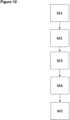
- the assembly method comprises the steps: axially moving (step M1) the connecting bolt with assembly locking device in the direction of the central longitudinal axis into the component opening of the component, during the axially moving of the connecting bolt with assembly locking device into the component opening of the component, generating a relative rotation (step M2) between the component opening and the connecting bolt with assembly locking device, so that the assembly locking device decreases an outer diameter of the clamping coil portion within the component opening, stopping the axial moving (step M3) of the connecting bolt with assembly locking device into the component opening of the component and generating a contrary relative rotation (step M4) compared with step M2, so that the assembly locking device increases the outer diameter of the clamping coil portion within the component opening and retains the connecting bolt in the component opening in a releasable manner.
- step M2 rotating the thread bolt with assembly locking device in turn direction of the assembly locking device while the assembly locking device is fixedly held by means of the holding turn on the connecting bolt, so that the outer diameter of the clamping coil portion decreases.
- step M3 rotating the thread bolt with assembly locking device contrary to the turn direction of the assembly locking device while the assembly locking device is fixedly held on the connecting bolt by means of the holding turn so that the outer diameter of the clamping coil portion increases.
- the assembly method has the further step (step M5): rotating the connecting bolt with assembly locking device in a thread direction of the thread on the shaft and thereby fastening the connecting bolt in a receiving thread of a further component.
- the present invention provides a further assembly method of a thread bolt in combination with a threaded bushing within a component opening having an inner thread of a component to be connected to another component.
- the assembly method comprises axially moving (step M1) the connecting bolt with assembly locking device and the threaded bushing in the direction of the central longitudinal axis into the component opening of the component, during the axially moving of the connecting bolt with assembly locking device and the threaded bushing into the component opening of the component, generating a relative rotation (step M2) between the component opening and the connecting bolt with assembly locking device and the threaded bushing, so that the threaded bushing is screwed into the threaded component opening, stopping the axial moving (step M3) of the connecting bolt with assembly locking device and the threaded bushing into the component opening of the component.
- the present invention further provides a connecting method of a first component and a second component, wherein the first component has a component opening being provided as a passage hole according to the above, and the second component has a second threaded opening adapted to the thread bolt, wherein the connecting method comprises the following steps: arranging the first component and the second component opposite to each other so that the thread bolt of the first component is aligned with the second threaded opening of the second component, compressing the axial locking device in an axial direction of the thread bolt thereby introducing a tip of the thread bolt into the threaded opening of the second component, screwing the thread bolt of the first component into the threaded opening of the second component so that the first and the second component are connected to each other.
- the present invention discloses a connecting method of a first component and a second component with tolerance compensation between the first and the second component, wherein the first component has a threaded component opening being provided as a passage hole, wherein in the threaded component opening, an outer threaded bushing in combination with the thread bolt and the assembly locking device as described above is arranged.
- the second component has a threaded opening adapted in size to the thread bolt
- the connecting method comprises the following steps: arranging the first component and the second component opposite to each other so that the thread bolt of the first component is aligned with the second threaded opening of the second component, rotating the threaded bushing of the first component to be displace in the direction of the second component for tolerance compensation therebetween, screwing the thread bolt of the first component into the second threaded opening of the second component so that the first and the second component are connected to each other.
- the assembly locking device 10 essentially consists of a wire coil 12 having a plurality of helically wound turns 14.
- the wire coil 12 has a first end and a second end.
- the assembly locking device 1 is adapted to retain itself on a shaft 32 of a connecting bolt 30, preferably a thread bolt having an outer thread on the shaft 32.
- the wire coil 12 provides a holding turn 16 at its first end which is described in greater detail below.
- the holding turn 16 is adapted in diameter to the shaft 32 of the threaded bolt 30 to realize a resilient gripping or a resilient holding of the wire coil 12 on the shaft 32, preferably adjacent to a bottom of a head 34 of the thread bolt 30.
- the assembly locking device 1 is adapted to resiliently retain itself in a component opening 82 of a component 80 to be connected to a further component 90.
- the wire coil 12 has an intermediate clamping coil portion 18 which is arranged between the holding turn 16 and a positioning turn 20 (see below). Based on the preferred truncated cone shape S of the external contour of the clamping coil 18, the assembly locking device 1 may be reduced and expanded in diameter by turning the wire coil 12 in and opposed to a turn direction of the wire coil 12.
- This functionality enables a facilitated insertion or installation of the assembly locking device 1 holding a thread bolt 30 within the component opening 82. Further preferred, this functionality supports a self-retaining of the assembly locking device 1 holding a thread bolt 30 within the opening 82.
- the wire coil 12 resiliently expands after insertion into the opening 82. Thereby, at least one turn of the clamping coil portion 18 is fastened by frictional forces at an inner wall of the component 82.
- the turns of the clamping coil portion 18 are expanded in diameter by rotation of the wire coil 12 in its turn direction R W . Thereby, the turns of the clamping coil portion 18 are forced radially outwardly against the inner wall of the component opening 82 or against an inner wall of a threaded bushing 86 for tolerance compensation (see below).
- the holding turn 16 extends over an angular range of at least 360° about the central longitudinal axis L of the wire coil 12. Further, the holding turn 14 has an inner diameter D H as shown in figures 1 and 3 .
- the holding turn 16 retains the assembly locking device 1 on the shaft 32, preferably directly below the head 34 of the thread bolt 30.
- the holding turn 16 preferably has a smaller inner diameter as compared to the outer diameter of the shaft 32. Based thereon, the holding turn 16 is resiliently fixed on the shaft 32 below the head 34.
- the clamping coil portion 18 has a plurality of subsequent turns of increasing inner diameter D K (see figure 1 ).
- the diameter D K increases as compared to the diameter D H of the holding turn 16.
- the clamping coil portion 18 preferably has a larger pitch P W as compared to the holding turn 16.
- the increased pitch P W realizes a larger axial distance between adjacent turns to achieve a higher radial deformability of the clamping coil portion 16.
- the clamping coil portion 18 is preferably qualified by a higher radial flexibility and/or elastic deformability distant from the holding turn 16 as close to the holding turn 16. Since the positioning turn 20 pre-orientates and/or loosely holds the shaft 32 in a distant from the head 34 and adjacent to the clamping coil portion 18, the positioning turn 20 benefits from the flexibility of the clamping coil portion 18 to align the shaft 32 of the connecting bolt 30.
- the positioning turns 20 at the second end of the wire coil 12 extend over an angular range of at least 270° about the longitudinal axis L. Furthermore, it has an inner diameter D P for which applies D K >D P ⁇ D H .
- the positioning coil 20 receives the leading tip of the shaft 32 of the bolt 30. Thereby, the shaft 32 is aligned preferably parallel to the longitudinal axis L by the combined holding effect of the holding turn 14 and the positioning turn 20.
- the positioning turn 20 is intended to align the shaft 32 with the assembly locking device 1, preferably with its longitudinal axis L, and thereby also with a longitudinal axis of the component opening 82. To this end, a sufficient radial stability of the positioning turn 20 is achieved by using a smaller or no pitch P W compared to the pitch of the clamping coil portion 16.
- a last turn of the positioning turn 20 is arranged at the end of the wire coil 12.
- An adjacent preceding turn has an increasing inner diameter as compared to the last turn.
- the last turn and the preceding before last turn are arranged in a common plane perpendicular to the longitudinal axis L. Thereby, the positioning function of the positioning turn 20 is preferably guaranteed.
- a retaining portion 19 is provided at the end of the clamping coil portion 18 facing the positioning turn 20.
- the clamping coil portion 18 is directly connected to the retaining portion 19 and thereby forms a bridging coil portion between the clamping coil portion 18 and the positioning turn 20.
- the retaining portion 19 realizes a frictional contact interface to an inner wall of the component opening 82. Based thereon, the retaining portion 19 additionally provides a frictionally type connection between the assembly locking device 1 and the component 80 via the inner wall of the component opening 82.
- the cylindrical retaining portion 19 extends over an angular range of at least 270°, preferably at least 360 °, about the central longitudinal axis L of the wire coil 12.
- at least 90 % of the retaining portion 19, more preferred 100 % contact the inner wall of the component opening 82 after pre-installation of the connecting bolt 30 within the component opening 82.
- the contact is preferably enabled by a constant minimum radius of the wire turn of the retaining portion 19 with respect to the longitudinal center middle axis L of the wire coil 12.
- the holding turn 16 extends over at least 720°. With increasing angular extension of the holding turns 16, an interface between the holding turns 16 and the thread bolt 30 is increased which also increases frictional forces therebetween.
- adjacent windings of the holding turn 16 are wound on block to support the stability of the holding turns 16.
- the shaft 32 is connected to the bottom side of the head 34 based on different configurations as shown in figures 4 and 5 .
- the shaft 32 is directly connected to the bottom side of the head 34. It is also preferred to use a transition shoulder 38 or a transition groove 36 for connecting the shaft 32 with the bottom side of the head 34.
- the lateral extension of the transition shoulder 38 or the transition groove 36 is preferably in proportion to an outer thread used on the shaft 32 of the bolt 30.
- the present invention preferably uses a standard thread on the shaft 32 which is qualified by a core diameter according to known and accepted international standards.
- the transition shoulder 38 as well as the transition groove 36 are preferably configured and dimensioned with respect to the core diameter d 3 of the standard thread used on the shaft 32.
- the transition shoulder 38 preferably has an outer diameter d S (see figure 5 ) being larger than the core diameter d 3 .
- the transition groove 36 preferably has an outer diameter being smaller than the core diameter d 3 .
- the inner diameter D H of the holding turn 16 is preferably defined as follows
- the transition shoulder 38 has the outer diameter d S .
- the outer diameter d S of the transition shoulder 38 is
- the inner diameter of the holding turn D H is defined as
- the assembly locking device 1 is preferably adapted to be arranged on the thread bolt 30 having the bolt head 34, the thread shaft 32 and the standard thread 33 (see Figure 4 ).
- the standard thread 16 which can be right-handed or left-handed, is a normalized standard thread RG or a normalized fine thread FG.
- the geometric data of the normalized standard thread 33 are defined in known DIN standards, so that preferably the assembly locking device 1 is provided on the basis of the normalized geometric data.
- the geometric data of the normalized standard thread RG which are also referred to as nominal dimensions, are specified in the DIN standards DIN 13-1 and DIN 13-12.
- the geometric data describing the normalized standard thread RG include the nominal diameter d RG , the pitch P RG , the flank diameter d 2, RG and the core diameter d 3, RG . These geometrical data also define a normalized fine thread FG.
- Table 1 shows an extract of the geometric data for the standard thread RG according to DIN 13-1. In Table 1, a portion for the nominal diameter d RG of 1 mm ⁇ d RG ⁇ 18 mm is defined in combination with values for the pitch P RG in the range of 0.25 mm ⁇ P RG ⁇ 2.5 mm.
- Table 2 shows an extract of the geometric data for the fine pitch thread FG according to DIN 13-4.
- Table 2 refers only to values of the nominal diameter d FG , the flank diameter d 2, FG and the core diameter d 3, FG for a pitch P FG of 0.75 mm.
- the wire from which the assembly locking device 1 is wound preferably comprises a round cross-section, as shown in Figures 1 to 3 . It is also preferred to use a wire with an elliptical cross-section or a rhombic cross-section or a cross-section rounded on one side.
- the different cross-sectional shapes are used in dependence thereon to increase a retention of the assembly locking device 1 on the thread 33 of the thread bolt 30 or on an inner component wall.
- the wire of the assembly locking device is comprised of a spring-elastic material with sufficient tensile strength either made of metal or of plastic material.
- the spring wire or the plastic wire of the wire coil 12 has a thickness in the range of 0.3 mm to 1.7 mm.
- the holding turn 16 starts at the first end of the wire coil 12 with a tangentially extending tang 17.
- This construction preferably realizes a distance between the thread 33 on the shaft 32 and sharp edges or burr at the cut first end of the wire coil 12.
- the wire coil 12 is wound from an endless wire.
- each wire forming a wire coil 12 has to be cut from the endless wire.
- the cutting process generates sharp edges or burr which leads to damage of the thread 33 on the shaft 32. Therefore, the tangential tang 17 realizes a protecting distance of the cut wire end to the thread 33 of the thread bolt 30.
- the clamping coil portion 18 preferably has a truncated cone shape in its outer of contour. It is such oriented that the smallest extension of the clamping coil portion 18 is adjacent to the holding turn 16. Starting from this position, the clamping coil portion 18 preferably expands continuously in its diameter in the direction of the positioning turn 20. Close to the positioning turn 20, it has the largest radial extension.
- the holding turn 16 retains the thread bolt 13 in the center of the assembly locking device 1.
- the clamping coil 18 is adapted to be forced into component openings of different size and/or shape to retain therein the assembly locking device 1 and thereby the thread bolt 30 asserted by frictional forces.
- the resiliently deformable wire of the wire coil 12 enables the clamping coil portion 16 to be adapted to different shapes and sizes of the component opening 82. After elastic deformation of the clamping coil portion 18, e. g. after insertion into the component opening 82 being smaller in diameter than the clamping coil portion 16, the clamping coil portion 16 attempts to return to its original shape. This intrinsic effort of the clamping coil portion 18 generates the clamping frictional forces between the clamping coil portion 18 and the inner wall of the component opening 82.
- the inner diameter D K of the clamping coil portion 18 is D H ⁇ D K ⁇ 10 D H , preferably 1.5 D H ⁇ D K ⁇ 8 D H .
- the clamping coil portion 18 Based on the shape of the clamping coil portion 18, the clamping coil portion 18 provides a plurality of increasing inner diameters D K based on the plurality of turns forming the clamping coil portion 18. Each single turn is preferably sufficient to resiliently retain the assembly locking device 1 with the thread bolt 30 within the opening 82.
- the holding turn 16 and the positioning turn 20 would form the poles of the spheric assembly locking device 1 which are connected by the longitudinal axis L.
- the thread bolt 30 having a standard thread 33 is assembled with the assembly locking device 1 as exemplarily shown in figures 4 and 5 .
- the thread bolt 30 of figure 4 comprises the transition groove 36.
- the transition groove 36 has a certain depth measured perpendicular to the longitudinal axis L. It is also preferred to reduce the depth of the transition groove 36 to zero.
- Figure 5 shows a thread bolt 30 comprising the transition shoulder 38.
- the inner diameter D H of the holding turn 16 is adapted to the size D S of the transition shoulder 38.
- the assembly locking device 1 is mounted in the loss proof manner on the thread bolt 30 having the transition groove 36 or the transition shoulder 38.
- the clamping coil portion 18 retains the assembly locking device 1 in combination with the thread bolt 30 within the component opening 82, it has an outer diameter of D M in the range of
- the component opening 82 is a stepped through hole. It is also preferred to provide a component 80 having a straight through hole to preinstall and retain the assembly locking device 1 in combination with the thread bolt 30.
- the assembly locking device 1 has a turn direction R W .
- the wire coil 12 starts at the holding turn 16 and it regularly runs down an axial direction to the positioning turned 20.
- a relative rotation between the component opening 82 and the thread bolt 13 is made in opposite direction to the turn direction R W .
- the thread bolt 30 is preferably turned against the turn direction R W .
- the holding turn 16 fastens the wire coil 12 on the shaft 32.
- the wire coil 12 is wound closer or tighter to the shaft 32 by turning the shaft 32 against the turn direction R W and by frictionally holding or slowing down the clamping coil portion 18 at the inner wall of the component opening 82. Thereby, the preinstallation in the component opening 82 is facilitated.
- the thread bolt 30 still holding the assembly locking device 1 is turned in turn direction R W to enlarge the diameter D M of the clamping coil portion 18. Thereby, frictional forces between the clamping coil portion 18 and the inner wall of the component opening 82 are increased and retain the assembly locking device 1 with the thread bolt 30 within the component opening 82.
- the thread bolt 30 is preferably screwed in a threaded opening 92 of the second component 90 (see figure 7 ).
- the second component 90 is placed opposed to the first component 80 so that the thread bolt 30 and the threaded opening 92 are co-axially aligned to each other.
- the preferred threaded opening 92 is formed by an inner thread of an opening, by a blind rivet nut, by nut, by a weld nut or the like of the second component 90.
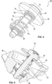
- the clamping coil portion 18 is pre-installed (as described above) in an inner opening 88 of an outer threaded bushing 86 (see figure 8 ).
- the combination of the assembly locking device 1, the threaded bolt 30 and the preinstalled threaded bushing 86 is preferably used as a unit for tolerance compensation between a first part 80 and second part 90.
- the component opening 82 of the first component 80 preferably comprises an inner thread 84 adapted to the outer thread of the outer threaded bushing 86.
- the unit comprising the assembly locking device bond, the thread bolt 30, and the threaded bushing 86 is preferably provided separately to the first component 80 or preinstalled in the opening 82 of the first component 80 as shown in figure 8 .
- the threaded bushing 86 installed in the component opening 82 serves for bridging a distance D between the first component 80 and a second component 90. To this end, the bushing 86 is rotated to be displaced in the direction of the second component 90. As soon the bushing 86 abuts at the second component 90, the rotation of the bushing 86 is stopped. Thereafter, this thread bolt 30 is screwed in the threaded opening 92 of the second component 90 so that first 80 and second component 90 are fixed to each other.
- the thread bolt 30 holding the assembly locking device 1 is preferably turned in turn direction R W of the wire coil 12. Based on the friction between the inner wall of the inner opening 88 of the bushing 86 and the clamping coil portion 18, the rotation of the thread bolt 30 tries to enlarge the outer diameter D M of the clamping coil portion 18. Thereby, the friction is increased between the inner wall of the inner opening 88 and the clamping coil portion 18. This preferably allows the thread bolt 30 to rotate the bushing 86.
- the thread bolt 30 turns the bushing 86 in a clockwise direction as the turn direction R W is running, if seen from the bolt head 34.
- the inner thread 84 of the first component 18 as well as of the bushing 86 is preferably left-handed. If the turn direction R W is anticlockwise, the inner thread 84 and the thread of the outer threaded bushing 86 are right-handed. Preferably, the thread direction of the thread bolt 30 is equal to the turn direction R W .
- the inner opening 88 of the threaded bushing 86 has a stepped configuration with respect to its longitudinal axis.
- the inner opening 88 has a larger diameter in the first starting section and a smaller diameter in a subsequent section.
- This axially stepped configuration guarantees that the assembly locking device 1 and in particular the clamping quarry portion 18 is sufficiently received in the inner opening 88.
- the clamping coil portion 18 preferably realizes frictional anchoring, and thereby connection between the clamping quarry portion 18 and the threaded bushing 86.
- the thread bolt 30 is reliably pre-installed thereby. Furthermore, the stepped configuration prevents that the assembly locking device 1 is pushed through the opening 82 with no fastening of the assembly locking device 1.
- the assembly locking device 1 cannot be pushed through the opening 88. Furthermore, the frictional connection between the thread bolt 30 and the threaded bushing 86 by means of the assembly locking device 1 guarantees a torque transfer from the thread bolt 30 to the threaded bushing 86. Thereby, the threaded bushing 86 is used for tolerance compensation. Furthermore, the thread bolt 30 is preferably kept within the opening 88 until the outer threaded bushing 86 abuts the second component 90.
- the threaded bushing 86 preferably has a friction ring 89 arranged on the outer thread of the bushing 86.
- the friction ring 89 preferably made of elastic material, has contact to the inner thread 84 of the component opening 82. Based on this arrangement, the friction ring 89 prevents a release of the threaded bushing 86 by vibration and/or during transport.
- first component 18 with a preinstalled thread bushing 86 in combination with the assembly locking device 1 and the thread bolt 30. This pre-installed assembly is also bound together by means of the friction ring 89 during transport.
- the assembly method refers to the thread bolt 30 having a direct connection between the shaft 32 and the head 34 or having the transition groove 36 or the transition shoulder 38 arranged therebetween. Said thread bolt 30 is arranged within the component opening 82 of the first component 80 to be connected to the second component 90.
- the assembly method comprises the steps: axially moving (step M1) the connecting bolt 30 with assembly locking device 1 in the direction of the central longitudinal axis L into the component opening 82 of the component 80, during the axially moving of the connecting bolt with assembly locking device 1 into the component opening 82 of the component, generating a relative rotation (step M2) between the component opening 82 and the connecting bolt 30 with assembly locking device 1, so that the assembly locking device 1 decreases an outer diameter of the clamping coil portion 18 within the component opening 82, stopping the axial moving (step M3) of the connecting bolt with assembly locking device 1 into the component opening 82 of the component and generating a contrary relative rotation (step M4) compared with step M2, so that the assembly locking device 1 increases the outer diameter of the clamping coil portion 18 within the component opening 82 and retains the connecting bolt 30 in the component opening 82 in a releasable manner.
- An alternative assembly method is directed to pre-installing the above described thread bolt 30 in the inner opening 88 of the outer threaded bushing 88 arranged within the component opening 82 having an inner thread.
- the assembly method comprises the steps: axially moving (step M1) the connecting bolt with assembly locking device 1 in the direction of the central longitudinal axis into an inner opening 88 of the outer threaded bushing 86 arranged within the component opening 82 of the component, during the axially moving of the connecting bolt 30 with assembly locking device 1 into the inner opening 88 of the threaded bushing 86, generating a relative rotation (step M2) between the inner opening 88 and the connecting bolt with assembly locking device 1, so that the assembly locking device 1 decreases an outer diameter of the clamping coil portion 18 within the inner opening 88, stopping the axial moving (step M3) of the connecting bolt with assembly locking device 1 into the inner opening 88 of the threaded bushing 86 and generating a contrary relative rotation (step M4) compared with step M2, so that the assembly locking device 1 increases the outer diameter
- step M2 rotating the thread bolt 30 with assembly locking device 1 in turn direction R W of the assembly locking device 1 while the assembly locking device 1 is fixedly held by means of the holding turn 14 on the connecting bolt, so that the outer diameter of the clamping coil portion 18 decreases.
- step M3 rotating the thread bolt 30 with assembly locking device 1 contrary to the turn direction R W of the assembly locking device 1 while the assembly locking device 1 is fixedly held on the connecting bolt by means of the holding turn 14 so that the outer diameter of the clamping coil portion 18 increases.
- step M1 axially moving (step M1) the connecting bolt with assembly locking device 1 and the threaded bushing in the direction of the central longitudinal axis into the component opening 82 of the component, during the axially moving of the connecting bolt with assembly locking device 1 and the threaded bushing into the component opening 82 of the component, generating a relative rotation (step M2) between the component opening 82 and the connecting bolt with assembly locking device 1 and the threaded bushing, so that the threaded bushing 86 is screwed in the threaded component opening 82, stopping the axial moving (step M3) of the connecting bolt with assembly locking device 1 and the threaded bushing into the component opening 82 of the component.
- the first component 80 has the component opening 82 being provided as a passage hole and the second component 90 has the second threaded opening adapted to the thread bolt 30.
- the following steps are preferably carried out: arranging the first component and the second component opposite to each other so that the thread bolt 30 of the first component is aligned with the second threaded opening of the second component, compressing the axial locking device 1 in an axial direction of the thread bolt 30 thereby introducing a tip of the thread bolt 30 into the threaded opening of the second component, screwing the thread bolt 30 of the first component into the threaded opening of the second component so that the first and the second component are connected to each other.
- connection method comprises the following steps: arranging the first component and the second component opposite to each other so that the thread bolt 30 of the first component is aligned with the second threaded opening of the second component, rotating the threaded bushing of the first component to be displace in the direction of the second component for tolerance compensation therebetween, screwing the thread bolt 30 of the first component into the second threaded opening of the second component so that the first and the second component are connected to each other.
- the above connecting method comprises the further step: rotating the thread bolt 30 together with the assembly locking device 1 so that the torque of the thread bolt 30 is transferred by friction to the threaded bushing for tolerance compensation between the first and the second component.
- it comprises the further step: abutting at the second component by the threaded bushing so that the rotation of the threaded bushing is stopped despite of further rotating the thread bolt 30.
- the above described assembly locking device 1 is preferably manufactured based on the following method steps: winding the wire to form the wire coil 12 consisting of a plurality of screw-like wound windings of the wire, having a first and a second end, wherein starting (S1) at the first end of the wire coil 12, the holding turn 14 is provided which extends over an angular range of at least 360° about the central longitudinal axis L of the wire coil 12 and comprises an inner diameter D H , following the holding turn 14, the clamping coil portion 18 is arranged (S2) that is formed like the truncated cone having the plurality of subsequent turns of an increasing inner diameter D K compared with the holding turn 14, with the clamping coil portion 18 extending over at least two turns about the central longitudinal axis L of the wire coil and comprises a pitch P W that is larger compared with the holding turn 14, and following the clamping coil portion 18 and at the end of the second end of the wire coil 12, the positioning turn is provided (S3), extending over the angular range of at least 270° about the central
Priority Applications (2)
| Application Number | Priority Date | Filing Date | Title |
|---|---|---|---|
| EP22306132.6A EP4311949A1 (fr) | 2022-07-28 | 2022-07-28 | Dispositif de verrouillage d'ensemble, boulon de connexion en combinaison avec le dispositif de verrouillage d'ensemble, composant avec un boulon de connexion préinstallé au moyen du dispositif de verrouillage d'ensemble ainsi qu'un procédé de fabrication pour le dispositif de verrouillage d'ensemble et un procédé d'assemblage d'un boulon de connexion avec le dispositif de verrouillage d'ensemble dans une ouverture de composant |
| US18/227,000 US20240035511A1 (en) | 2022-07-28 | 2023-07-27 | Assembly locking device, a connecting bolt in combination with the assembly locking device, a component with a pre-installed connecting bolt by means of the assembly locking device as well as a manufacturing method for the assembly locking device and an assembly method of a connecting bolt with the assembly locking device within a component opening |
Applications Claiming Priority (1)
| Application Number | Priority Date | Filing Date | Title |
|---|---|---|---|
| EP22306132.6A EP4311949A1 (fr) | 2022-07-28 | 2022-07-28 | Dispositif de verrouillage d'ensemble, boulon de connexion en combinaison avec le dispositif de verrouillage d'ensemble, composant avec un boulon de connexion préinstallé au moyen du dispositif de verrouillage d'ensemble ainsi qu'un procédé de fabrication pour le dispositif de verrouillage d'ensemble et un procédé d'assemblage d'un boulon de connexion avec le dispositif de verrouillage d'ensemble dans une ouverture de composant |
Publications (1)
| Publication Number | Publication Date |
|---|---|
| EP4311949A1 true EP4311949A1 (fr) | 2024-01-31 |
Family
ID=82846305
Family Applications (1)
| Application Number | Title | Priority Date | Filing Date |
|---|---|---|---|
| EP22306132.6A Pending EP4311949A1 (fr) | 2022-07-28 | 2022-07-28 | Dispositif de verrouillage d'ensemble, boulon de connexion en combinaison avec le dispositif de verrouillage d'ensemble, composant avec un boulon de connexion préinstallé au moyen du dispositif de verrouillage d'ensemble ainsi qu'un procédé de fabrication pour le dispositif de verrouillage d'ensemble et un procédé d'assemblage d'un boulon de connexion avec le dispositif de verrouillage d'ensemble dans une ouverture de composant |
Country Status (2)
| Country | Link |
|---|---|
| US (1) | US20240035511A1 (fr) |
| EP (1) | EP4311949A1 (fr) |
Citations (6)
| Publication number | Priority date | Publication date | Assignee | Title |
|---|---|---|---|---|
| US2201930A (en) * | 1938-01-04 | 1940-05-21 | Kastar Inc | Self-locking bolt for automobile license plates |
| US3263728A (en) | 1964-02-20 | 1966-08-02 | Republic Ind Corp | Captive bolt |
| DE29724014U1 (de) * | 1996-06-13 | 1999-10-07 | Bergner Richard Gmbh Co | Montage-Baugruppe |
| DE102009036820A1 (de) | 2009-08-04 | 2011-02-10 | Illinois Tool Works Inc., Glenview | Befestigungsmittel zur Vormontage eines Verbindungsmittels an einem Bauteil |
| US9664226B2 (en) | 2013-04-05 | 2017-05-30 | Richard Bergner Verbindungstechnik Gmbh & Co. Kg | Assembly unit |
| US20180195540A1 (en) * | 2013-09-20 | 2018-07-12 | Böllhoff Verbindungstechnik GmbH | Spring connection element |
-
2022
- 2022-07-28 EP EP22306132.6A patent/EP4311949A1/fr active Pending
-
2023
- 2023-07-27 US US18/227,000 patent/US20240035511A1/en active Pending
Patent Citations (6)
| Publication number | Priority date | Publication date | Assignee | Title |
|---|---|---|---|---|
| US2201930A (en) * | 1938-01-04 | 1940-05-21 | Kastar Inc | Self-locking bolt for automobile license plates |
| US3263728A (en) | 1964-02-20 | 1966-08-02 | Republic Ind Corp | Captive bolt |
| DE29724014U1 (de) * | 1996-06-13 | 1999-10-07 | Bergner Richard Gmbh Co | Montage-Baugruppe |
| DE102009036820A1 (de) | 2009-08-04 | 2011-02-10 | Illinois Tool Works Inc., Glenview | Befestigungsmittel zur Vormontage eines Verbindungsmittels an einem Bauteil |
| US9664226B2 (en) | 2013-04-05 | 2017-05-30 | Richard Bergner Verbindungstechnik Gmbh & Co. Kg | Assembly unit |
| US20180195540A1 (en) * | 2013-09-20 | 2018-07-12 | Böllhoff Verbindungstechnik GmbH | Spring connection element |
Also Published As
| Publication number | Publication date |
|---|---|
| US20240035511A1 (en) | 2024-02-01 |
Similar Documents
| Publication | Publication Date | Title |
|---|---|---|
| US11512732B2 (en) | Tolerance compensation assembly | |
| US7048487B2 (en) | Connector | |
| RU2291326C2 (ru) | Компенсирующее допуски монтажное устройство | |
| US4481702A (en) | Method of assembling threaded insert bushing within a working material | |
| US7306418B2 (en) | Deforming member and captive fastener retaining method | |
| EP0746695B1 (fr) | Fixation en aveugle avec un manchon deformable | |
| EP2452083B1 (fr) | Dispositif de liaison mécanique d'au moins deux pièces comprenant des axes coaxiaux | |
| US11754103B2 (en) | Tolerance compensation assembly | |
| JP4224480B2 (ja) | ねじ山形成ねじを採用した固定装置 | |
| WO1996031706A1 (fr) | Attache | |
| US20170266794A1 (en) | Drive Element for Transmitting a Torque to a Threaded Insert Sleeve | |
| CN102022408A (zh) | 具有螺栓和螺母的螺纹接头 | |
| EP4311949A1 (fr) | Dispositif de verrouillage d'ensemble, boulon de connexion en combinaison avec le dispositif de verrouillage d'ensemble, composant avec un boulon de connexion préinstallé au moyen du dispositif de verrouillage d'ensemble ainsi qu'un procédé de fabrication pour le dispositif de verrouillage d'ensemble et un procédé d'assemblage d'un boulon de connexion avec le dispositif de verrouillage d'ensemble dans une ouverture de composant | |
| EP3336372B1 (fr) | Mélangeur comprenant un ensemble de manchon de serrage | |
| US20200108475A1 (en) | Press-in connecting element and method for anchoring press-in connecting elements in a permanently deformable flat metal material or components or workpieces produced therefrom | |
| US3415153A (en) | Mechanical clamping device | |
| US4475859A (en) | Rivetless anchor nut and method | |
| CN1252495A (zh) | 安装元件 | |
| CN115867731A (zh) | 自成型螺纹单面紧固件 | |
| EP4336058A1 (fr) | Élément d'insertion et son procédé de réglage | |
| US11739780B2 (en) | Functional element | |
| US20210277929A1 (en) | Assembly locking device, thread bolt with assembly locking device, a component with installed thread bolt as well as a manufacturing method for the assembly locking device and an assembly method of the thread bolt with assembly locking device | |
| US20240011521A1 (en) | Fastening device | |
| CN115768988A (zh) | 盲铆钉元件,尤其是用于在构件中建立螺纹连接 | |
| CN117377832A (zh) | 调节元件、带有调节元件的第一部件、包括第一部件的连接结构、调节元件的制造方法和连接方法 |
Legal Events
| Date | Code | Title | Description |
|---|---|---|---|
| PUAI | Public reference made under article 153(3) epc to a published international application that has entered the european phase |
Free format text: ORIGINAL CODE: 0009012 |
|
| STAA | Information on the status of an ep patent application or granted ep patent |
Free format text: STATUS: REQUEST FOR EXAMINATION WAS MADE |
|
| 17P | Request for examination filed |
Effective date: 20230914 |
|
| AK | Designated contracting states |
Kind code of ref document: A1 Designated state(s): AL AT BE BG CH CY CZ DE DK EE ES FI FR GB GR HR HU IE IS IT LI LT LU LV MC MK MT NL NO PL PT RO RS SE SI SK SM TR |
|
| RAP1 | Party data changed (applicant data changed or rights of an application transferred) |
Owner name: BOLLHOFF OTALU S.A.S. |