EP4311945A1 - Emergency operating valve block for a mobile crane - Google Patents
Emergency operating valve block for a mobile crane Download PDFInfo
- Publication number
- EP4311945A1 EP4311945A1 EP22187446.4A EP22187446A EP4311945A1 EP 4311945 A1 EP4311945 A1 EP 4311945A1 EP 22187446 A EP22187446 A EP 22187446A EP 4311945 A1 EP4311945 A1 EP 4311945A1
- Authority
- EP
- European Patent Office
- Prior art keywords
- valve block
- check valves
- connection
- engine
- valve
- Prior art date
- Legal status (The legal status is an assumption and is not a legal conclusion. Google has not performed a legal analysis and makes no representation as to the accuracy of the status listed.)
- Pending
Links
- 239000012530 fluid Substances 0.000 claims description 27
- 230000000903 blocking effect Effects 0.000 claims description 4
- 238000009434 installation Methods 0.000 description 4
- 238000012423 maintenance Methods 0.000 description 3
- 206010034016 Paronychia Diseases 0.000 description 2
- 238000010586 diagram Methods 0.000 description 2
- 230000005484 gravity Effects 0.000 description 2
- 238000007789 sealing Methods 0.000 description 2
- LLJRXVHJOJRCSM-UHFFFAOYSA-N 3-pyridin-4-yl-1H-indole Chemical compound C=1NC2=CC=CC=C2C=1C1=CC=NC=C1 LLJRXVHJOJRCSM-UHFFFAOYSA-N 0.000 description 1
- 208000012886 Vertigo Diseases 0.000 description 1
- 238000010276 construction Methods 0.000 description 1
- 230000008878 coupling Effects 0.000 description 1
- 238000010168 coupling process Methods 0.000 description 1
- 238000005859 coupling reaction Methods 0.000 description 1
Images

Classifications
-
- B—PERFORMING OPERATIONS; TRANSPORTING
- B66—HOISTING; LIFTING; HAULING
- B66C—CRANES; LOAD-ENGAGING ELEMENTS OR DEVICES FOR CRANES, CAPSTANS, WINCHES, OR TACKLES
- B66C13/00—Other constructional features or details
- B66C13/18—Control systems or devices
- B66C13/20—Control systems or devices for non-electric drives
-
- B—PERFORMING OPERATIONS; TRANSPORTING
- B66—HOISTING; LIFTING; HAULING
- B66C—CRANES; LOAD-ENGAGING ELEMENTS OR DEVICES FOR CRANES, CAPSTANS, WINCHES, OR TACKLES
- B66C23/00—Cranes comprising essentially a beam, boom, or triangular structure acting as a cantilever and mounted for translatory of swinging movements in vertical or horizontal planes or a combination of such movements, e.g. jib-cranes, derricks, tower cranes
- B66C23/88—Safety gear
- B66C23/90—Devices for indicating or limiting lifting moment
-
- B—PERFORMING OPERATIONS; TRANSPORTING
- B66—HOISTING; LIFTING; HAULING
- B66C—CRANES; LOAD-ENGAGING ELEMENTS OR DEVICES FOR CRANES, CAPSTANS, WINCHES, OR TACKLES
- B66C23/00—Cranes comprising essentially a beam, boom, or triangular structure acting as a cantilever and mounted for translatory of swinging movements in vertical or horizontal planes or a combination of such movements, e.g. jib-cranes, derricks, tower cranes
- B66C23/88—Safety gear
-
- F—MECHANICAL ENGINEERING; LIGHTING; HEATING; WEAPONS; BLASTING
- F15—FLUID-PRESSURE ACTUATORS; HYDRAULICS OR PNEUMATICS IN GENERAL
- F15B—SYSTEMS ACTING BY MEANS OF FLUIDS IN GENERAL; FLUID-PRESSURE ACTUATORS, e.g. SERVOMOTORS; DETAILS OF FLUID-PRESSURE SYSTEMS, NOT OTHERWISE PROVIDED FOR
- F15B13/00—Details of servomotor systems ; Valves for servomotor systems
- F15B13/02—Fluid distribution or supply devices characterised by their adaptation to the control of servomotors
- F15B13/06—Fluid distribution or supply devices characterised by their adaptation to the control of servomotors for use with two or more servomotors
- F15B13/08—Assemblies of units, each for the control of a single servomotor only
- F15B13/0803—Modular units
- F15B13/0807—Manifolds
- F15B13/0814—Monoblock manifolds
-
- F—MECHANICAL ENGINEERING; LIGHTING; HEATING; WEAPONS; BLASTING
- F15—FLUID-PRESSURE ACTUATORS; HYDRAULICS OR PNEUMATICS IN GENERAL
- F15B—SYSTEMS ACTING BY MEANS OF FLUIDS IN GENERAL; FLUID-PRESSURE ACTUATORS, e.g. SERVOMOTORS; DETAILS OF FLUID-PRESSURE SYSTEMS, NOT OTHERWISE PROVIDED FOR
- F15B13/00—Details of servomotor systems ; Valves for servomotor systems
- F15B13/02—Fluid distribution or supply devices characterised by their adaptation to the control of servomotors
- F15B13/06—Fluid distribution or supply devices characterised by their adaptation to the control of servomotors for use with two or more servomotors
- F15B13/08—Assemblies of units, each for the control of a single servomotor only
- F15B13/0803—Modular units
- F15B13/0832—Modular valves
-
- F—MECHANICAL ENGINEERING; LIGHTING; HEATING; WEAPONS; BLASTING
- F15—FLUID-PRESSURE ACTUATORS; HYDRAULICS OR PNEUMATICS IN GENERAL
- F15B—SYSTEMS ACTING BY MEANS OF FLUIDS IN GENERAL; FLUID-PRESSURE ACTUATORS, e.g. SERVOMOTORS; DETAILS OF FLUID-PRESSURE SYSTEMS, NOT OTHERWISE PROVIDED FOR
- F15B13/00—Details of servomotor systems ; Valves for servomotor systems
- F15B13/02—Fluid distribution or supply devices characterised by their adaptation to the control of servomotors
- F15B13/06—Fluid distribution or supply devices characterised by their adaptation to the control of servomotors for use with two or more servomotors
- F15B13/08—Assemblies of units, each for the control of a single servomotor only
- F15B13/0803—Modular units
- F15B13/0878—Assembly of modular units
- F15B13/0896—Assembly of modular units using different types or sizes of valves
-
- F—MECHANICAL ENGINEERING; LIGHTING; HEATING; WEAPONS; BLASTING
- F15—FLUID-PRESSURE ACTUATORS; HYDRAULICS OR PNEUMATICS IN GENERAL
- F15B—SYSTEMS ACTING BY MEANS OF FLUIDS IN GENERAL; FLUID-PRESSURE ACTUATORS, e.g. SERVOMOTORS; DETAILS OF FLUID-PRESSURE SYSTEMS, NOT OTHERWISE PROVIDED FOR
- F15B20/00—Safety arrangements for fluid actuator systems; Applications of safety devices in fluid actuator systems; Emergency measures for fluid actuator systems
- F15B20/002—Electrical failure
-
- F—MECHANICAL ENGINEERING; LIGHTING; HEATING; WEAPONS; BLASTING
- F16—ENGINEERING ELEMENTS AND UNITS; GENERAL MEASURES FOR PRODUCING AND MAINTAINING EFFECTIVE FUNCTIONING OF MACHINES OR INSTALLATIONS; THERMAL INSULATION IN GENERAL
- F16K—VALVES; TAPS; COCKS; ACTUATING-FLOATS; DEVICES FOR VENTING OR AERATING
- F16K11/00—Multiple-way valves, e.g. mixing valves; Pipe fittings incorporating such valves
- F16K11/10—Multiple-way valves, e.g. mixing valves; Pipe fittings incorporating such valves with two or more closure members not moving as a unit
- F16K11/14—Multiple-way valves, e.g. mixing valves; Pipe fittings incorporating such valves with two or more closure members not moving as a unit operated by one actuating member, e.g. a handle
-
- F—MECHANICAL ENGINEERING; LIGHTING; HEATING; WEAPONS; BLASTING
- F16—ENGINEERING ELEMENTS AND UNITS; GENERAL MEASURES FOR PRODUCING AND MAINTAINING EFFECTIVE FUNCTIONING OF MACHINES OR INSTALLATIONS; THERMAL INSULATION IN GENERAL
- F16K—VALVES; TAPS; COCKS; ACTUATING-FLOATS; DEVICES FOR VENTING OR AERATING
- F16K37/00—Special means in or on valves or other cut-off apparatus for indicating or recording operation thereof, or for enabling an alarm to be given
- F16K37/0008—Mechanical means
-
- F—MECHANICAL ENGINEERING; LIGHTING; HEATING; WEAPONS; BLASTING
- F15—FLUID-PRESSURE ACTUATORS; HYDRAULICS OR PNEUMATICS IN GENERAL
- F15B—SYSTEMS ACTING BY MEANS OF FLUIDS IN GENERAL; FLUID-PRESSURE ACTUATORS, e.g. SERVOMOTORS; DETAILS OF FLUID-PRESSURE SYSTEMS, NOT OTHERWISE PROVIDED FOR
- F15B2211/00—Circuits for servomotor systems
- F15B2211/30—Directional control
- F15B2211/305—Directional control characterised by the type of valves
- F15B2211/30525—Directional control valves, e.g. 4/3-directional control valve
-
- F—MECHANICAL ENGINEERING; LIGHTING; HEATING; WEAPONS; BLASTING
- F15—FLUID-PRESSURE ACTUATORS; HYDRAULICS OR PNEUMATICS IN GENERAL
- F15B—SYSTEMS ACTING BY MEANS OF FLUIDS IN GENERAL; FLUID-PRESSURE ACTUATORS, e.g. SERVOMOTORS; DETAILS OF FLUID-PRESSURE SYSTEMS, NOT OTHERWISE PROVIDED FOR
- F15B2211/00—Circuits for servomotor systems
- F15B2211/30—Directional control
- F15B2211/305—Directional control characterised by the type of valves
- F15B2211/3056—Assemblies of multiple valves
- F15B2211/30565—Assemblies of multiple valves having multiple valves for a single output member, e.g. for creating higher valve function by use of multiple valves like two 2/2-valves replacing a 5/3-valve
- F15B2211/3057—Assemblies of multiple valves having multiple valves for a single output member, e.g. for creating higher valve function by use of multiple valves like two 2/2-valves replacing a 5/3-valve having two valves, one for each port of a double-acting output member
-
- F—MECHANICAL ENGINEERING; LIGHTING; HEATING; WEAPONS; BLASTING
- F15—FLUID-PRESSURE ACTUATORS; HYDRAULICS OR PNEUMATICS IN GENERAL
- F15B—SYSTEMS ACTING BY MEANS OF FLUIDS IN GENERAL; FLUID-PRESSURE ACTUATORS, e.g. SERVOMOTORS; DETAILS OF FLUID-PRESSURE SYSTEMS, NOT OTHERWISE PROVIDED FOR
- F15B2211/00—Circuits for servomotor systems
- F15B2211/30—Directional control
- F15B2211/315—Directional control characterised by the connections of the valve or valves in the circuit
- F15B2211/31523—Directional control characterised by the connections of the valve or valves in the circuit being connected to a pressure source and an output member
- F15B2211/31541—Directional control characterised by the connections of the valve or valves in the circuit being connected to a pressure source and an output member having a single pressure source and multiple output members
-
- F—MECHANICAL ENGINEERING; LIGHTING; HEATING; WEAPONS; BLASTING
- F15—FLUID-PRESSURE ACTUATORS; HYDRAULICS OR PNEUMATICS IN GENERAL
- F15B—SYSTEMS ACTING BY MEANS OF FLUIDS IN GENERAL; FLUID-PRESSURE ACTUATORS, e.g. SERVOMOTORS; DETAILS OF FLUID-PRESSURE SYSTEMS, NOT OTHERWISE PROVIDED FOR
- F15B2211/00—Circuits for servomotor systems
- F15B2211/30—Directional control
- F15B2211/315—Directional control characterised by the connections of the valve or valves in the circuit
- F15B2211/3157—Directional control characterised by the connections of the valve or valves in the circuit being connected to a pressure source, an output member and a return line
- F15B2211/31588—Directional control characterised by the connections of the valve or valves in the circuit being connected to a pressure source, an output member and a return line having a single pressure source and multiple output members
-
- F—MECHANICAL ENGINEERING; LIGHTING; HEATING; WEAPONS; BLASTING
- F15—FLUID-PRESSURE ACTUATORS; HYDRAULICS OR PNEUMATICS IN GENERAL
- F15B—SYSTEMS ACTING BY MEANS OF FLUIDS IN GENERAL; FLUID-PRESSURE ACTUATORS, e.g. SERVOMOTORS; DETAILS OF FLUID-PRESSURE SYSTEMS, NOT OTHERWISE PROVIDED FOR
- F15B2211/00—Circuits for servomotor systems
- F15B2211/30—Directional control
- F15B2211/32—Directional control characterised by the type of actuation
- F15B2211/321—Directional control characterised by the type of actuation mechanically
- F15B2211/324—Directional control characterised by the type of actuation mechanically manually, e.g. by using a lever or pedal
-
- F—MECHANICAL ENGINEERING; LIGHTING; HEATING; WEAPONS; BLASTING
- F15—FLUID-PRESSURE ACTUATORS; HYDRAULICS OR PNEUMATICS IN GENERAL
- F15B—SYSTEMS ACTING BY MEANS OF FLUIDS IN GENERAL; FLUID-PRESSURE ACTUATORS, e.g. SERVOMOTORS; DETAILS OF FLUID-PRESSURE SYSTEMS, NOT OTHERWISE PROVIDED FOR
- F15B2211/00—Circuits for servomotor systems
- F15B2211/70—Output members, e.g. hydraulic motors or cylinders or control therefor
- F15B2211/71—Multiple output members, e.g. multiple hydraulic motors or cylinders
- F15B2211/7135—Combinations of output members of different types, e.g. single-acting cylinders with rotary motors
-
- F—MECHANICAL ENGINEERING; LIGHTING; HEATING; WEAPONS; BLASTING
- F15—FLUID-PRESSURE ACTUATORS; HYDRAULICS OR PNEUMATICS IN GENERAL
- F15B—SYSTEMS ACTING BY MEANS OF FLUIDS IN GENERAL; FLUID-PRESSURE ACTUATORS, e.g. SERVOMOTORS; DETAILS OF FLUID-PRESSURE SYSTEMS, NOT OTHERWISE PROVIDED FOR
- F15B2211/00—Circuits for servomotor systems
- F15B2211/80—Other types of control related to particular problems or conditions
- F15B2211/875—Control measures for coping with failures
- F15B2211/8757—Control measures for coping with failures using redundant components or assemblies
Definitions
- the present invention relates to a valve block, by means of which it can be ensured in the event of a failure of the main energy supply to the engine drives that the engine engines can be supplied with hydraulic fluid via an independent emergency energy supply.
- the present invention further relates to a mobile crane with such a valve block with which the crane drives can be supplied by means of an emergency energy supply.
- Crane functions such as lifting or lowering a load on the hoist rope, luffing the crane boom in or out as well as rotating the crane superstructure relative to the crane undercarriage are regularly carried out in mobile cranes by hydraulic units such as hydraulic motors or cylinders. These in turn are driven by hydraulic pumps, to which they are connected via hydraulic lines in order to be supplied with a volume flow of hydraulic fluid.
- hydraulic units such as hydraulic motors or cylinders.
- hydraulic pumps to which they are connected via hydraulic lines in order to be supplied with a volume flow of hydraulic fluid.
- So-called “transformers” represent an example of such an independent energy supply and essentially consist of a gear motor-pump combination that can be driven by an external hydraulic energy source and delivers drive power to a hydraulic gear pump.
- the external hydraulic energy source can be provided, for example, by another crane or a hydraulic unit, a so-called “power pack”.
- the gear pump can, for example, take hydraulic fluid from the superstructure tank of the receiver crane and provides the hydraulic pressure and volume flow for the delivery supplying engines ready. Since the hydraulic main drive system is not used, the engines are driven with reduced power.
- Previous emergency drive systems have a large number of valves that have to be manually operated in a precisely specified manner in order to control a desired engine in the desired manner.
- the individual valves are combined in a compact unit.
- a piping or even tubing between the individual valves, as in this case corresponding devices from the prior art are the case, can therefore be omitted.
- the hydraulic connection between the individual valves and also other hydraulic components takes place through channels formed in the valve block body, so that compared to known systems with valves that are piped or hose-connected to one another, not only the maintenance effort can be reduced to a considerable extent, but also the construction volume taken up by the valve system.
- the valve block accommodating the individual valves does not necessarily have to be designed as a one-piece body, but rather can also have a modular structure and have several module bodies that are hydraulically connected to one another.
- this makes it possible not only to detach individual hydraulic components from the rest of the valve block for maintenance or repair purposes, but also to replace them with new components.
- valve block according to the invention can provide an engine connection for any engine drive in order to connect it to an emergency drive device.
- the check valves and/or the actuation valve are designed to be actuated by means of a hand lever, with the actuation of the check valves being designed in particular in such a way that simultaneous opening of several check valves is prevented.
- each of the valves it is therefore possible for each of the valves to have its own hand lever, which operating personnel can use to move the valve into a desired position.
- the levers can be designed in such a way that a lever physically blocks the other levers as soon as it is brought into a position by the operating personnel in which the associated valve is opened, i.e. connects the corresponding power drive with the emergency drive device.
- each of the check valves having a tool handle with which the hand lever can be releasably coupled.
- the lever Before the lever is connected to a valve to be opened, it must first be removed from the previously operated valve, which creates a further indication for operating personnel to close the previously operated valve first.
- valve block can further be simplified by the hand lever or the tool handles of the check valves being arranged and/or aligned in an identical manner on the valve block, in particular in an adjacent manner.
- This measure means that all available valves and their operating levers are visible to operating personnel at the same time.
- valves arranged in the same way the respective actuation position of all valves can also be seen.
- the valves can be arranged in such a way that a certain spatial direction of the hand lever or the tool grip indicates the same actuation position for all valves, for example "open” or "closed”
- the position of the hand lifting or the tool attacks of the check valves can be fixed mechanically, in particular in their position blocking the hydraulic connection between the drive connection and the engine connection assigned to them. This prevents uncontrolled opening of individual valves.
- the check valves in particular their tool handles or their hand levers, can have a position indicator, in particular in the form of a recess or a projection on the tool handle or hand lever.
- a position indicator in particular in the form of a recess or a projection on the tool handle or hand lever.
- valves Any suitable design of the valves is conceivable for opening or blocking the hydraulic connection between the drive connection and the respective engine connections.
- rotary slide valves represent a preferred embodiment of a check valve because of their compact design.
- these check valves can be designed as 6/2-way valves, with which 6 hydraulic connections can be connected in 2 different valve positions.
- the actuating valve can be designed as a 5/3-way valve, which interconnects 5 hydraulic connections in 3 different positions.
- the check valves serve the function of releasing or blocking a hydraulic connection between the drive connection and the respective engine connection.
- a “pre-selection” of a power plant to be driven with the emergency drive device can be carried out.
- the actuating valve can not only have the task of defining the direction of movement or rotation of the power drive to be driven, but also an additional locking option for the hydraulic connection between the drive connection and the respective engine connections.
- the hydraulic connection can ultimately be released by opening the actuating valve in a direction corresponding to the desired direction of movement of the crane engine in order to immediately drive the corresponding crane engine via the emergency drive device.
- the direction of movement of the engine depends on which of the engine's hydraulic supply lines is connected to a pressure side or a return side of the drive connection via the actuating valve.
- the actuating valve can be arranged in the hydraulic connection of the drive port with the engine ports between the drive port and the check valves.
- a separate actuating valve can also be provided for each engine connection, which are arranged between the corresponding check valves and the drive connections assigned to them.
- the actuation valve can be designed so that in a basic position it does not supply at least one of the check valves with a feed pressure.
- the valve block can also have one or more lowering brake valves, which prevent a return movement of crane drives caused by gravity.
- the valve block can have at least one lowering brake valve, which can also be used is designed to either release or block a hydraulic connection between the return sides of a corresponding engine connection and the drive connection.
- the actuating valve can also supply the lowering brake valve(s) with working pressure.
- one embodiment of the valve block has at least one hydraulic connection, which serves to return hydraulic fluid emerging as a leak from at least one of the check valves and / or from the actuating valve to the drive connection.
- a further aspect of the present invention relates to a mobile crane with an emergency drive device, at least two crane drives, in particular assigned to the superstructure, and an emergency operation valve block in one of the embodiments described above.
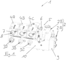
- the Figure 1 shows a valve block 1 according to the invention with a base body 10, on which three check valves 4A, 4B, 4C, an actuating valve 5 and a lowering brake valve 9 are mounted in such a way that their inner fluid channels are fluidly connected to those of the base body 10. Piping or tubing for the individual hydraulic components is therefore not necessary in the valve block 1 according to the invention. Rather, there is a “direct” transfer of hydraulic fluid here between the individual components, which are connected to each other via sealing contact surfaces.
- the valve block to be seen has three identical check valves 4A, 4B, 4C, which are each assigned to a power drive, for example a slewing gear, a luffing gear and a hoist of a mobile crane and are hydraulically connected to corresponding engine connections 3A, 3B, 3C.
- the check valves 4A, 4B, 4C are designed in an identical manner and are also arranged in an identical orientation on the base body 10, so that actuation can take place by means of a hand lever, not shown, which can be detachably coupled to the respective tool attacks 7.
- each valve 4A, 4B, 4C is displayed via a slot 8 incorporated into the front of the tool attachment 7, for the position of which a legend attached to the base body 10 provides an aid to interpretation:
- the hydraulic connection is to the engine connection 3A, 3B, 3C locked, which is the usual position for normal crane operation.
- the corresponding check valve 4A, 4B, 4C is open, so that a power unit connected to the corresponding engine connection 3A, 3B, 3C can be supplied with hydraulic fluid in emergency operation.
- the individual tool attacks 7 can be mechanically locked in a closed position of the valves 4A, 4B, 4C, for example by in the Figure 1 folding pins visible.
- the valve block 1 also has an actuating valve 5, which is connected on the one hand to each of the check valves 4A, 4B, 4C and on the other hand to a drive connection 2.
- actuating valve 5 which is connected on the one hand to each of the check valves 4A, 4B, 4C and on the other hand to a drive connection 2.
- actuation valve 5 also assigning the pressure side 2A and the return side 2B of the drive connection 2 to the respective sides of the engine connections 3A, 3B, 3C takes place in order to specify the direction of movement of the engine engines.
- valve block 1 has a lowering brake valve 9 for corresponding engine connections 3A, 3B, 3C.
- valve block 1 not only enables a quick exchange of individual components, but also the optional installation of different components according to the respective installation situation of the valve block 1 in, for example, different types of cranes.
- FIG. 2 shows a hydraulic circuit diagram for the in the Figure 1 Valve block 1 can be seen.
- the function and operation of the valve block 1 will be explained below with reference to Figure 2 take place.
- a volume flow of hydraulic fluid is provided by a transformer via the pressure side 2A of the drive connection 2.
- the basic position of the actuating valve 5 can be seen, the hydraulic fluid circulates on the pressure side 2A.
- the pressure relief valve DBV 2 limits the feed pressure and opens at approx. 30 bar.
- the feed pressure is present at all check valves 4A, 4B, 4C.
- the feed pressure is available via the check valve 4A at the (not labeled) valve for connecting the slewing gear brake BR.
- connection H2 By opening the check valve 4B with the actuating valve 5 closed, hydraulic fluid under feed pressure reaches connection H2, so that a hoist brake connected to it opens.
- the actuating valve 5 is moved to its lowest position so that returning hydraulic fluid from the engine is present at the lowering brake valve 9A.
- there is working pressure on the pressure side 2A at the lowering brake valve 9A which opens due to this pressure addition.
- the load-lifting hydraulic fluid can therefore flow towards the tank via the actuation valve 5 and the pressure relief valve DBV 2.
- the burden is lowering.
- the returning hydraulic fluid from the engine returns to the tank via the check valve 4B, the actuation valve 5 and the pressure relief valve DBV 2.
- the actuating valve 5 To rock out, the actuating valve 5 is brought to its lowest position so that hydraulic fluid reaches the pressure reducing valve 9B via the orifice N2. The luffing cylinder slowly retracts and the boom lowers. The returning hydraulic fluid from the cylinder flows back into the tank via a crane control block, not shown here.
Abstract
Die Erfindung betrifft einen Notbetriebs-Ventilblock (1) mit einem Antriebs-Anschluss (2) zur hydraulischen Verbindung des Ventilblocks (1) mit einer Notantriebseinrichtung eines Mobilkrans, zumindest zwei Triebwerks-Anschlüssen (3A, 3B, 3C) zur hydraulischen Verbindung des Ventilblocks (1) mit je einem Triebwerk des Mobilkrans, zumindest zwei Sperrventilen (4A, 4B, 4C), welche jeweils einem der Triebwerks-Anschlüsse (3A, 3B, 3C) zugeordnet und dazu ausgestaltet sind, eine hydraulische Verbindung zwischen dem Antriebs-Anschluss (2) und dem ihnen jeweils zugeordneten Triebwerks-Anschluss (3A, 3B, 3C) wahlweise freizugeben oder zu sperren, und einem Betätigungsventil (5), welches dazu ausgestaltet ist, die hydraulische Verbindung zwischen einer Druckseite (2A) und einer Rücklaufseite (2B) des Antriebs-Anschlusses (2) mit entsprechenden Seiten der Triebwerks-Anschlüsse (3A, 3B, 3C) wahlweise umzukehren. Die Erfindung betrifft ferner einen Mobilkran mit einem solchen Notbetriebs-Ventilblock.The invention relates to an emergency operation valve block (1) with a drive connection (2) for hydraulically connecting the valve block (1) to an emergency drive device of a mobile crane, at least two engine connections (3A, 3B, 3C) for hydraulically connecting the valve block ( 1) each with an engine of the mobile crane, at least two check valves (4A, 4B, 4C), which are each assigned to one of the engine connections (3A, 3B, 3C) and are designed to provide a hydraulic connection between the drive connection (2 ) and the engine connection (3A, 3B, 3C) assigned to them to either release or block, and an actuating valve (5), which is designed to ensure the hydraulic connection between a pressure side (2A) and a return side (2B) of the Drive connection (2) with corresponding sides of the engine connections (3A, 3B, 3C) can optionally be reversed. The invention further relates to a mobile crane with such an emergency operation valve block.
Description
Die vorliegende Erfindung betrifft einen Ventilblock, mittels welchem bei einem Ausfall der Hauptenergieversorgung der Krantriebwerke sichergestellt werden kann, dass die Krantriebwerke über eine unabhängige Notenergieversorgung mit Hydraulikflüssigkeit versorgt werden können. Die vorliegende Erfindung betrifft ferner einen Mobilkran mit einem solchen Ventilblock, mit dem die Versorgung der Krantriebwerke mittels einer Notenergieversorgung erfolgen kann.The present invention relates to a valve block, by means of which it can be ensured in the event of a failure of the main energy supply to the engine drives that the engine engines can be supplied with hydraulic fluid via an independent emergency energy supply. The present invention further relates to a mobile crane with such a valve block with which the crane drives can be supplied by means of an emergency energy supply.
Kranfunktionen wie beispielsweise das Heben oder Senken einer Last am Hubseil, das Ein- oder Auswippen des Kranauslegers wie auch das Drehen des Kranoberwagens gegenüber dem Kranunterwagen werden bei Mobilkranen regelmäßig von hydraulischen Aggregaten wie etwa Hydraulikmotoren oder -zylindern durchgeführt. Diese werden wiederum von Hydraulikpumpen angetrieben, mit welchen sie über Hydraulikleitungen verbunden sind, um mit einen Volumenstrom an Hydraulikflüssigkeit versorgt zu werden. Um bei einem Schadensfall wesentliche Kranfunktionen weiterhin durchführen zu können, ist es wünschenswert und teilweise sogar gesetzlich vorgeschrieben, ein vom Hauptantriebssystem unabhängiges Antriebssystem vorzusehen.Crane functions such as lifting or lowering a load on the hoist rope, luffing the crane boom in or out as well as rotating the crane superstructure relative to the crane undercarriage are regularly carried out in mobile cranes by hydraulic units such as hydraulic motors or cylinders. These in turn are driven by hydraulic pumps, to which they are connected via hydraulic lines in order to be supplied with a volume flow of hydraulic fluid. In order to be able to continue to perform essential crane functions in the event of damage, it is desirable and sometimes even required by law to provide a drive system that is independent of the main drive system.
Sogenannte "Transformatoren" stellen ein Beispiel für eine solche unabhängige Energieversorgung dar und bestehen im Wesentlichen aus einer Zahnradmotor-Pumpenkombination, die von einer externen hydraulischen Energiequelle angetrieben werden kann und Antriebsleistung an eine hydraulische Zahnradpumpe abgibt. Die externe hydraulische Energiequelle kann beispielsweise von einem weiteren Kran oder aber auch einem Hydraulikaggregat, einem sogenannten "Powerpack" bereitgestellt werden. Die Zahnradpumpe kann beispielsweise Hydraulikflüssigkeit aus dem Oberwagentank des Empfängerkrans entnehmen und stellt den hydraulischen Druck und Volumenstrom für die zu versorgenden Triebwerke bereit. Da hierbei nicht auf das hydraulische Hauptantriebssystem zurückgegriffen wird, werden die Triebwerke mit verminderter Leistung angetrieben. Bisherige Notantriebssysteme weisen hierbei eine Vielzahl von Ventilen auf, die in einer exakt vorgegebenen Weise manuell betätigt werden müssen, um ein gewünschtes Triebwerk in gewünschter Weise anzusteuern. Ferner wurden diese Systeme bislang individuell an einen Kran angepasst und sind daher aus einer Vielzahl von Hydraulikkomponenten aufgebaut, die für den Bediener oftmals in unübersichtlicher Weise verrohrt sind. Sie weisen daher regelmäßig eine unbefriedigende Lekageneigung auf und beanspruchen einen nicht zu vernachlässigenden Bauraum, wobei deren Unübersichtlichkeit oftmals zu Fehlbedienungen führt.So-called “transformers” represent an example of such an independent energy supply and essentially consist of a gear motor-pump combination that can be driven by an external hydraulic energy source and delivers drive power to a hydraulic gear pump. The external hydraulic energy source can be provided, for example, by another crane or a hydraulic unit, a so-called “power pack”. The gear pump can, for example, take hydraulic fluid from the superstructure tank of the receiver crane and provides the hydraulic pressure and volume flow for the delivery supplying engines ready. Since the hydraulic main drive system is not used, the engines are driven with reduced power. Previous emergency drive systems have a large number of valves that have to be manually operated in a precisely specified manner in order to control a desired engine in the desired manner. Furthermore, these systems have so far been individually adapted to a crane and are therefore made up of a large number of hydraulic components, which are often piped in a way that is confusing for the operator. They therefore regularly have an unsatisfactory tendency to leak and take up a not negligible amount of installation space, with their lack of clarity often leading to incorrect operation.
Es ist die Aufgabe der vorliegenden Erfindung, hier Abhilfe zu schaffen und eine kompakte, wartungsarme wie auch für einen Bediener leicht verständliche Vorrichtung bereitzustellen, mittels welcher einzelne Krantriebwerke hydraulisch mit einer Notantriebseinrichtung verbunden werden und von dieser angetrieben werden können.It is the object of the present invention to remedy this and to provide a device that is compact, low-maintenance and easy for an operator to understand, by means of which individual crane drives can be hydraulically connected to an emergency drive device and driven by it.
Diese Aufgabe wird durch einen Ventilblock gemäß der vorliegenden Erfindung gelöst, welcher folgende Komponenten aufweist:
- einen Antriebs-Anschluss zur hydraulischen Verbindung des Ventilblocks mit einer Notantriebseinrichtung eines Mobilkrans;
- zumindest zwei Triebwerks-Anschlüsse zur hydraulischen Verbindung des Ventilblocks mit je einem Triebwerk des Mobilkrans;
- zumindest zwei Sperrventile, welche jeweils einem der Triebwerks-Anschlüsse zugeordnet und dazu ausgestaltet sind, eine hydraulische Verbindung zwischen dem Antriebs-Anschluss und dem ihnen jeweils zugeordneten Triebwerks-Anschluss wahlweise freizugeben oder zu sperren, und
- ein Betätigungsventil, welches dazu ausgestaltet ist, die hydraulische Verbindung zwischen einer Druckseite und einer Rücklaufseite des Antriebs-Anschlusses mit entsprechenden Seiten der Triebwerks-Anschlüsse wahlweise umzukehren.
- a drive connection for hydraulically connecting the valve block to an emergency drive device of a mobile crane;
- at least two engine connections for hydraulically connecting the valve block to one engine of the mobile crane;
- at least two check valves, each of which is assigned to one of the engine connections and is designed to selectively release or block a hydraulic connection between the drive connection and the engine connection assigned to them, and
- an actuation valve configured to selectively reverse the hydraulic connection between a pressure side and a return side of the drive port with corresponding sides of the engine ports.
Erfindungsgemäß werden die einzelnen Ventile in einer kompakten Einheit zusammengefasst. Eine Verrohrung oder gar Verschlauchung der einzelnen Ventile untereinander, wie dies bei entsprechenden Vorrichtungen aus dem Stand der Technik der Fall ist, kann somit entfallen. Vielmehr erfolgt die hydraulische Verbindung zwischen den einzelnen Ventilen und auch weiteren hydraulischen Komponenten durch im Ventilblockkörper ausgebildete Kanäle, sodass gegenüber bekannten Systemen mit untereinander verrohrten oder verschlauchten Ventilen nicht nur der Wartungsaufwand in erheblichem Maße reduziert werden kann, sondern auch das vom Ventilsystem eingenommene Bauvolumen.According to the invention, the individual valves are combined in a compact unit. A piping or even tubing between the individual valves, as in this case corresponding devices from the prior art are the case, can therefore be omitted. Rather, the hydraulic connection between the individual valves and also other hydraulic components takes place through channels formed in the valve block body, so that compared to known systems with valves that are piped or hose-connected to one another, not only the maintenance effort can be reduced to a considerable extent, but also the construction volume taken up by the valve system.
Der die einzelnen Ventile aufnehmende Ventilblock muss hierbei nicht zwingend als einteiliger Körper ausgeführt sein, sondern kann vielmehr auch modular aufgebaut sein und mehrere hydraulisch miteinander in Verbindung stehende Modulkörper aufweisen. So ist es beispielsweise möglich, den erfindungsgemäßen Ventilblock zu modifizieren, um diesen an verschiedene Einbausituationen anzupassen, etwa für unterschiedlichen Krantypen, deren Krantriebwerke sich nach Art und Anzahl voneinander unterscheiden können. Ferner ist es dadurch möglich, einzelne hydraulische Komponenten nicht nur zu Wartungs- oder Reparaturzwecken vom übrigen Ventilblock zu lösen, sondern diese auch durch neue Komponenten zu ersetzen.The valve block accommodating the individual valves does not necessarily have to be designed as a one-piece body, but rather can also have a modular structure and have several module bodies that are hydraulically connected to one another. For example, it is possible to modify the valve block according to the invention in order to adapt it to different installation situations, for example for different types of cranes whose crane drives can differ from one another in type and number. Furthermore, this makes it possible not only to detach individual hydraulic components from the rest of the valve block for maintenance or repair purposes, but also to replace them with new components.
Gemäß einer Ausführungsform weist der Ventilblock für zumindest zwei der folgenden Krantriebwerke je einen Triebwerks-Anschluss auf:
- Drehwerk zum Drehen des Kran-Oberwagens gegenüber dem Kran-Unterwagen;
- Wippwerk zum Einwippen und Auswippen des Kranauslegers;
- Hubwerk zum Heben und Senken der an einem Hubseil angehängten Last.
- Slewing gear for turning the crane uppercarriage relative to the crane undercarriage;
- Luffing gear for luffing in and out of the crane boom;
- Hoist for raising and lowering the load suspended on a hoist rope.
Selbstverständlich kann der erfindungsgemäße Ventilblock für beliebige Krantriebwerke einen Triebwerks-Anschluss bereitstellen, um diese mit einer Notantriebseinrichtung zu verbinden.Of course, the valve block according to the invention can provide an engine connection for any engine drive in order to connect it to an emergency drive device.
Gemäß einer weiteren Ausführungsform sind die Sperrventile und/oder das Betätigungsventil ausgestaltet, mittels eines Handhebels betätigt zu werden, wobei die Betätigung der Sperrventile insbesondere so ausgestaltet ist, dass eine gleichzeitige Öffnung von mehreren Sperrventilen verhindert wird.According to a further embodiment, the check valves and/or the actuation valve are designed to be actuated by means of a hand lever, with the actuation of the check valves being designed in particular in such a way that simultaneous opening of several check valves is prevented.
So ist es möglich, dass jedes der Ventile einen eigenen Handhebel aufweist, über welchen Bedienpersonal das Ventil in eine gewünschte Stellung bringen kann. Um Fehlbedienungen zu vermeiden, können die Hebel dabei so ausgestaltet sein, dass ein Hebel die jeweils anderen Hebel physisch blockiert, sobald er vom Bedienpersonal in eine Stellung gebracht wird, in welcher das dazugehörige Ventil geöffnet ist, also das entsprechende Krantriebwerk mit der Notantriebseinrichtung verbindet.It is therefore possible for each of the valves to have its own hand lever, which operating personnel can use to move the valve into a desired position. In order to avoid incorrect operation, the levers can be designed in such a way that a lever physically blocks the other levers as soon as it is brought into a position by the operating personnel in which the associated valve is opened, i.e. connects the corresponding power drive with the emergency drive device.
So kann sichergestellt werden, dass eine hydraulische Verbindung der Notantriebseinrichtung mit jeweils immer nur einem Krantriebwerk besteht und es folglich zu keinen unkontrollierten Stellbewegungen weiterer Krantriebwerke kommt.In this way it can be ensured that there is a hydraulic connection of the emergency drive device to only one power drive at a time and that there are therefore no uncontrolled actuating movements of other power drives.
Weiterhin ist es möglich, für die Sperrventile einen gemeinsamen Handhebel bereitzustellen, wobei jedes der Sperrventile einen Werkzeugangriff aufweist, mit welchem der Handhebel lösbar gekoppelt werden kann. Auch auf diese Weise kann vermieden werden, dass mehrere Ventile gleichzeitig geöffnet werden und so einen hydraulische Verbindung zwischen mehreren Krantriebwerken mit der Notantriebseinrichtung besteht. Bevor der Hebel mit einem zu öffnenden Ventil verbunden wird, muss dieser erst vom zuvor betätigten Ventil abgenommen werden, was für Bedienpersonal einen weiteren Hinweis schafft, das zuvor betätigte Ventil erst zu schließen. Als weitere Maßnahme wäre es möglich, die Kopplung zwischen dem gemeinsam bereitgestellten Handhebel und den einzelnen Ventilen so auszugestalten, dass der Handhebel nur in einer Schließstellung der Ventile von diesen abgenommen werden kann.Furthermore, it is possible to provide a common hand lever for the check valves, each of the check valves having a tool handle with which the hand lever can be releasably coupled. In this way it can also be avoided that several valves are opened at the same time and so there is a hydraulic connection between several crane drives and the emergency drive device. Before the lever is connected to a valve to be opened, it must first be removed from the previously operated valve, which creates a further indication for operating personnel to close the previously operated valve first. As a further measure, it would be possible to design the coupling between the jointly provided hand lever and the individual valves in such a way that the hand lever can only be removed from the valves when they are in a closed position.
Die Bedienung des Ventilblocks kann weiterhin dadurch vereinfacht werden, indem der Handhebel oder die Werkzeugangriffe der Sperrventile in identischer Weise am Ventilblock angeordnet und/oder ausgerichtet sind, insbesondere in aneinander angrenzender Weise. Durch diese Maßnahme sind sämtliche zur Verfügung stehenden Ventile bzw. deren Betätigungshebel für Bedienpersonal gleichzeitig erkennbar. Bei gleichartig angeordneten Ventilen ist zugleich auch die jeweilige Betätigungsstellung sämtlicher Ventile erkennbar. Beispielsweise können die Ventile so angeordnet sein, dass eine bestimmte Raumrichtung des Handhebels bzw. des Werkzeugangriffs für sämtliche Ventile die gleiche Betätigungsstellung angibt, beispielsweise "offen" bzw. "geschlossen"The operation of the valve block can further be simplified by the hand lever or the tool handles of the check valves being arranged and/or aligned in an identical manner on the valve block, in particular in an adjacent manner. This measure means that all available valves and their operating levers are visible to operating personnel at the same time. With valves arranged in the same way, the respective actuation position of all valves can also be seen. For example, the valves can be arranged in such a way that a certain spatial direction of the hand lever or the tool grip indicates the same actuation position for all valves, for example "open" or "closed"
Ferner ist es möglich, dass der Handheben oder die Werkzeugangriffe der Sperrventile in ihrer Stellung mechanisch festlegbar ist/sind, insbesondere in ihrer die hydraulische Verbindung zwischen dem Antriebs-Anschluss und dem ihnen jeweils zugeordneten Triebwerks-Anschluss sperrenden Position. Hierdurch wird ein unkontrolliertes Öffnen einzelner Ventile verhindert.Furthermore, it is possible that the position of the hand lifting or the tool attacks of the check valves can be fixed mechanically, in particular in their position blocking the hydraulic connection between the drive connection and the engine connection assigned to them. This prevents uncontrolled opening of individual valves.
Um die Betätigungsstellung der Ventile in einfacher Weise ersichtlich zu machen, können die Sperrventile, insbesondere deren Werkzeugangriffe oder deren Handhebel eine Stellungsanzeige aufweisen, im Speziellen in Form einer Vertiefung oder eines Vorsprungs am Werkzeugangriff oder Handhebel. Insbesondere wenn sämtliche Ventile in gleichartiger Weise angeordnet und/oder ausgerichtet sind, ist die Stellung sämtlicher Ventile sofort ersichtlich.In order to make the actuation position of the valves easily visible, the check valves, in particular their tool handles or their hand levers, can have a position indicator, in particular in the form of a recess or a projection on the tool handle or hand lever. In particular, if all valves are arranged and/or aligned in the same way, the position of all valves is immediately apparent.
Zum Öffnen bzw. Sperren der hydraulischen Verbindung zwischen dem Antriebs-Anschluss und den jeweiligen Triebwerks-Anschlüssen ist jede geeignete Ausgestaltung der Ventile vorstellbar. Im Rahmen der vorliegenden Erfindung stellen Drehschieberventile eine bevorzugte, weil kompakt bauende Ausführung eines Sperrventils dar. Ferner können diese Sperrventile als 6/2-Wegeventile ausgebildet sein, mit welchen jeweils 6 hydraulische Anschlüsse in 2 verschiedenen Ventilstelllungen verschaltet sein können. Auch für das Betätigungsventil sind grundsätzliche alle geeigneten Ausführungsformen vorstellbar, allerdings wird auch hier die Ausführung als Drehschieberventil aufgrund seiner Kompaktheit bevorzugt. Ferner kann das Betätigungsventil als 5/3-Wegeventil ausgebildet sein, welches 5 hydraulische Anschlüsse in 3 verschiedenen Stellungen miteinander verschaltet.Any suitable design of the valves is conceivable for opening or blocking the hydraulic connection between the drive connection and the respective engine connections. In the context of the present invention, rotary slide valves represent a preferred embodiment of a check valve because of their compact design. Furthermore, these check valves can be designed as 6/2-way valves, with which 6 hydraulic connections can be connected in 2 different valve positions. In principle, all suitable embodiments are also conceivable for the actuating valve, although here too the design as a rotary slide valve is preferred due to its compactness. Furthermore, the actuating valve can be designed as a 5/3-way valve, which interconnects 5 hydraulic connections in 3 different positions.
Die jeweils einem der Triebwerks-Anschlüsse zugeordneten Sperrventile dienen ihrer Funktion nach dazu, eine hydraulische Verbindung zwischen dem Antriebs-Anschluss und dem jeweiligen Triebwerks-Anschluss freizugeben bzw. zu sperren. Mittels der Sperrventile kann so eine "Vorauswahl" eines mit der Notantriebseinrichtung anzutreibenden Krantriebwerks erfolgen. Dem Betätigungsventil kann hierbei nicht nur die Aufgabe zukommen, die Bewegungs- oder Drehrichtung des jeweils anzutreibenden Krantriebwerks zu definieren, sondern auch eine zusätzliche Sperrmöglichkeit der hydraulischen Verbindung zwischen dem Antriebs-Anschluss und den jeweiligen Triebwerksanschlüssen bereitzustellen. Sobald also mittels der Sperrventile eine Auswahl des anzutreibenden Kranztriebwerks getroffen wurde, kann durch Öffnen des Betätigungsventils in einer der gewünschten Bewegungsrichtung des Krantriebwerks entsprechenden Richtung die hydraulische Verbindung letztendlich freigegeben werden, um das entsprechende Krantriebwerk sogleich über die Notantriebseinrichtung anzutreiben. Die Bewegungsrichtung des Krantriebwerks hängt davon ab, welche der hydraulischen Zuleitungen des Triebwerks über das Betätigungsventil mit einer Druckseite bzw. einer Rücklaufseite des Antriebs-Anschlusses verbunden wird. Um sich die Funktion des Betätigungsventils für sämtliche Triebwerks-Anschlüsse nutzbar zu machen, kann das Betätigungsventil in der hydraulischen Verbindung des Antriebs-Anschlusses mit den Triebwerks-Anschlüssen zwischen dem Antriebs-Anschluss und den Sperrventilen angeordnet sein. Alternativ kann auch für jeden Triebwerks-Anschluss ein eigenes Betätigungsventil vorgesehen sein, welche zwischen den entsprechenden Sperrventilen und den ihnen zugeordneten Antriebs-Anschlüssen angeordnet sind.The check valves, each assigned to one of the engine connections, serve the function of releasing or blocking a hydraulic connection between the drive connection and the respective engine connection. By means of the check valves, a “pre-selection” of a power plant to be driven with the emergency drive device can be carried out. The actuating valve can not only have the task of defining the direction of movement or rotation of the power drive to be driven, but also an additional locking option for the hydraulic connection between the drive connection and the respective engine connections. As soon as a selection of the ring engine to be driven has been made using the check valves, the hydraulic connection can ultimately be released by opening the actuating valve in a direction corresponding to the desired direction of movement of the crane engine in order to immediately drive the corresponding crane engine via the emergency drive device. The direction of movement of the engine depends on which of the engine's hydraulic supply lines is connected to a pressure side or a return side of the drive connection via the actuating valve. In order to make the function of the actuating valve usable for all engine connections, the actuating valve can be arranged in the hydraulic connection of the drive port with the engine ports between the drive port and the check valves. Alternatively, a separate actuating valve can also be provided for each engine connection, which are arranged between the corresponding check valves and the drive connections assigned to them.
In weiteren Ausführungsformen kann das Betätigungsventil ausgestaltet sein,
- in einer Grundstellung zumindest eines der Sperrventile mit einem Speisedruck zu versorgen, und insbesondere einen Umlauf von Hydraulikflüssigkeit von der Druckseite zur Rücklaufseite des Antriebs-Anschlusses zu ermöglichen;
- in einer Öffnungsstellung die Sperrventile mit einem Arbeitsdruck zu versorgen;
- in einer insbesondere zwischen der Grundstellung und einer der Öffnungsstellungen befindlichen Zwischenstellung zumindest eines der Sperrventile mit einem Speisedruck zu versorgen, und insbesondere einen Umlauf der Hydraulikflüssigkeit von der Druckseite zur Rücklaufseite des Antriebs-Anschlusses zu verhindern.
- in a basic position, to supply at least one of the check valves with a feed pressure, and in particular to enable a circulation of hydraulic fluid from the pressure side to the return side of the drive connection;
- to supply the check valves with a working pressure in an open position;
- in an intermediate position located in particular between the basic position and one of the open positions, to supply at least one of the check valves with a feed pressure, and in particular to prevent circulation of the hydraulic fluid from the pressure side to the return side of the drive connection.
Ferner kann das Betätigungsventil so ausgestaltet sein, dass es in einer Grundstellung zumindest eines der Sperrventile nicht mit einem Speisedruck versorgt.Furthermore, the actuation valve can be designed so that in a basic position it does not supply at least one of the check valves with a feed pressure.
Für einzelne Kranfunktionen kann der Ventilblock ferner ein oder mehrere Senkbremsventile aufweisen, welche eine durch Schwerkraft bedingte Rückstellbewegung von Krantriebwerken verhindern. So kann der Ventilblock zumindest ein Senkbremsventil aufweisen, welches dazu ausgestaltet ist, eine hydraulische Verbindung zwischen den Rücklaufseiten eines entsprechenden Triebwerks-Anschlusses und des Antriebs-Anschlusses wahlweise freizugeben oder zu sperren. Das Betätigungsventil kann das oder die Senkbremsventile ferner mit Arbeitsdruck versorgen.For individual crane functions, the valve block can also have one or more lowering brake valves, which prevent a return movement of crane drives caused by gravity. The valve block can have at least one lowering brake valve, which can also be used is designed to either release or block a hydraulic connection between the return sides of a corresponding engine connection and the drive connection. The actuating valve can also supply the lowering brake valve(s) with working pressure.
Zum Auffangen möglicher Leckage aus Ventilen, welche als Drehschieberventile ausgestaltet sein können, weist eine Aufführungsform des Ventilblocks zumindest eine hydraulische Verbindung auf, welche der Rückführung von aus zumindest einem der Sperrventile und/oder aus dem Betätigungsventil als Leckage austretender Hydraulikflüssigkeit zum Antriebs-Anschluss dient.To absorb possible leakage from valves, which can be designed as rotary slide valves, one embodiment of the valve block has at least one hydraulic connection, which serves to return hydraulic fluid emerging as a leak from at least one of the check valves and / or from the actuating valve to the drive connection.
Ein weiterer Aspekt der vorliegenden Erfindung betrifft einen Mobilkran mit einer Notantriebseinrichtung, zumindest zwei, insbesondere dem Oberwagen zugeordneten Krantriebwerken und einem Notbetriebs-Ventilblock in einer der oben beschriebenen Ausführungsformen.A further aspect of the present invention relates to a mobile crane with an emergency drive device, at least two crane drives, in particular assigned to the superstructure, and an emergency operation valve block in one of the embodiments described above.
Bevorzugte Ausführungsformen der vorliegenden Erfindung werden im Folgenden unter Bezugnahme auf die beiliegenden Figuren näher erläutert. Die vorliegende Erfindung kann sämtliche hierin beschriebenen Merkmale einzeln sowie in jedweder sinnvollen Kombination umfassen. Es zeigen:
- Figur 1:
- eine perspektivische Ansicht eines erfindungsgemäßen Notbetriebs-Ventilblocks;
- Figur 2:
- ein hydraulischer Schaltplan des Ventilblocks aus
Figur 1 .
- Figure 1:
- a perspective view of an emergency operation valve block according to the invention;
- Figure 2:
- a hydraulic circuit diagram of the valve block
Figure 1 .
Die
Der in
Der Ventilblock 1 weist ferner ein Betätigungsventil 5 auf, welches einerseits mit jedem der Sperrventile 4A, 4B, 4C und andererseits mit einem Antriebs-Anschluss 2 in Verbindung steht. Je nach Stellung des Handhebels 6 wird eine hydraulische Verbindung zwischen den Sperrventilen 4A, 4B, 4C und dem Antriebs-Anschluss 2 gesperrt oder freigegeben, wobei über das Betätigungsventil 5 ferner eine Zuordnung der Druckseite 2A und der Rücklaufseite 2B des Antriebsanschlusses 2 zu den jeweiligen Seiten der Triebwerks-Anschlüsse 3A, 3B, 3C stattfindet, um so die Bewegungsrichtung der Krantriebwerke vorzugeben.The
Um ungewollte, schwerkraftbedingte Stellbewegungen von Krantriebwerken zu verhindern, weist der Ventilblock 1 für entsprechende Triebwerks-Anschlüsse 3A, 3B, 3C ein Senkbremsventil 9 auf.In order to prevent unwanted, gravity-related adjustment movements of engine engines, the
Wie aus der
Die
Über die Druckseite 2A des Antriebs-Anschlusses 2 wird von einem Transformator ein Volumenstrom an Hydraulikflüssigkeit bereitgestellt. Bei der in der
Durch Öffnen des Sperrventils 4A steht der Speisedruck über das Sperrventil 4A am (nicht bezeichneten) Ventil für den Anschluss der Drehwerksbremse BR an.By opening the
Sobald das Betätigungsventil 5 in seine oberste Position verbracht und somit geöffnet wird, steht an sämtlichen Sperrventilen 4A, 4B, 4C Arbeitsdruck an. Durch das geöffnete Sperrventil 4A gelangt Hydraulikflüssigkeit über den Anschluss H5 zu den Drehwerksmotoren und bewirkt ein Drehen des Oberwagens. Die rücklaufende Hydraulikflüssigkeit aus den Motoren gelangt über den Anschluss H4, das Sperrventil 4A, das Betätigungsventil 5, das Druckbegrenzungsventil DBV 2 und die Rücklaufseite 2B des Antriebs-Anschlusses 2 zurück zum Hydrauliktank. Der Arbeitsdruck wird hierbei vom Druckbegrenzungsventil DBV 1 auf 195 bar begrenzt.As soon as the
Durch Öffnen des Sperrventils 4B bei geschlossenem Betätigungsventil 5 gelangt Hydraulikflüssigkeit unter Speisedruck zum Anschluss H2, so dass sich eine damit verbundene Hubwerksbremse öffnet.By opening the
Durch Öffnen des Betätigungsventils 5 (oberste Position) gelangt Hydraulikflüssigkeit unter Hochdruck zum Hubwerksmotor, so dass eine Last gehoben werden kann. Die rücklaufende Hydraulikflüssigkeit aus dem Motor fließt über das Sperrventil 4B, das Betätigungsventil 5 und das Druckbegrenzungsventil DBV 2 zurück in den Tank. Der Arbeitsdruck wird hierbei durch das Druckbegrenzungsventil DBV 1 auf 195 bar begrenzt.By opening the actuating valve 5 (top position), hydraulic fluid under high pressure reaches the hoist motor so that a load can be lifted. The returning hydraulic fluid from the engine flows back into the tank via the
Zum Senken der Last wird das Betätigungsventil 5 in seine unterste Stellung verbracht, so dass rücklaufende Hydraulikflüssigkeit aus dem Motor am Senkbremsventil 9A ansteht. Zusätzlich steht über die Druckseite 2A Arbeitsdruck am Senkbremsventil 9A an, das sich durch diese Druckaddition öffnet. Somit kann die lasthebende Hydraulikflüssigkeit über das Betätigungsventil 5 und das Druckbegrenzungsventil DBV 2 in Richtung Tank abfließen. Die Last senkt sich. Die rücklaufende Hydraulikflüssigkeit aus dem Motor gelangt über das Sperrventil 4B, das Betätigungsventil 5 und das Druckbegrenzungsventil DBV 2 zurück in den Tank.To lower the load, the
Beim Einwippen gelangt durch das geöffnete Betätigungsventil 5 (oberste Stellung) Hydraulikflüssigkeit unter Hochdruck durch das geöffnete Sperrventil 4C bis zum Anschluss H8 und den daran angeschlossenen Wippzylinder. Der Wippzylinder fährt in der Folge aus und der Ausleger hebt sich. Die rücklaufende Hydraulikflüssigkeit aus dem Zylinder fließt über einen nicht dargestellten Kransteuerblock zurück in den Tank.When rocking in, high-pressure hydraulic fluid flows through the open control valve 5 (top position) through the
Zum Auswippen wird das Betätigungsventil 5 in seine unterste Stellung gebracht, so dass Hydraulikflüssigkeit über die Blende N2 bis zum Druckminderventil 9B gelangt. Der Wippzylinder fährt langsam ein und der Ausleger senkt sich. Die rücklaufende Hydraulikflüssigkeit aus dem Zylinder fließt über einen hier nicht dargestellten Kransteuerblock zurück in den Tank.To rock out, the
Claims (15)
Priority Applications (4)
| Application Number | Priority Date | Filing Date | Title |
|---|---|---|---|
| EP22187446.4A EP4311945A1 (en) | 2022-07-28 | 2022-07-28 | Emergency operating valve block for a mobile crane |
| US18/354,416 US20240034601A1 (en) | 2022-07-28 | 2023-07-18 | Emergency-operation valve block for a mobile crane |
| CN202310890521.8A CN117466154A (en) | 2022-07-28 | 2023-07-19 | Emergency operation valve group for mobile crane |
| JP2023118802A JP2024019049A (en) | 2022-07-28 | 2023-07-21 | Emergency operating valve block for mobile cranes |
Applications Claiming Priority (1)
| Application Number | Priority Date | Filing Date | Title |
|---|---|---|---|
| EP22187446.4A EP4311945A1 (en) | 2022-07-28 | 2022-07-28 | Emergency operating valve block for a mobile crane |
Publications (1)
| Publication Number | Publication Date |
|---|---|
| EP4311945A1 true EP4311945A1 (en) | 2024-01-31 |
Family
ID=82781290
Family Applications (1)
| Application Number | Title | Priority Date | Filing Date |
|---|---|---|---|
| EP22187446.4A Pending EP4311945A1 (en) | 2022-07-28 | 2022-07-28 | Emergency operating valve block for a mobile crane |
Country Status (4)
| Country | Link |
|---|---|
| US (1) | US20240034601A1 (en) |
| EP (1) | EP4311945A1 (en) |
| JP (1) | JP2024019049A (en) |
| CN (1) | CN117466154A (en) |
Citations (3)
| Publication number | Priority date | Publication date | Assignee | Title |
|---|---|---|---|---|
| US2984985A (en) * | 1959-02-16 | 1961-05-23 | Macmillin Hydraulic Engineerin | Hydraulic operating and control system |
| GB969019A (en) * | 1961-03-15 | 1964-09-09 | John Milton Anthony Blatchford | Improvements in or relating to mobile cranes and similar vehicles |
| DE19646425A1 (en) * | 1996-11-11 | 1998-05-14 | Rexroth Mannesmann Gmbh | Valve system with valve housing in plate or compact block construction e.g. for tractor hydraulic attachments |
-
2022
- 2022-07-28 EP EP22187446.4A patent/EP4311945A1/en active Pending
-
2023
- 2023-07-18 US US18/354,416 patent/US20240034601A1/en active Pending
- 2023-07-19 CN CN202310890521.8A patent/CN117466154A/en active Pending
- 2023-07-21 JP JP2023118802A patent/JP2024019049A/en active Pending
Patent Citations (3)
| Publication number | Priority date | Publication date | Assignee | Title |
|---|---|---|---|---|
| US2984985A (en) * | 1959-02-16 | 1961-05-23 | Macmillin Hydraulic Engineerin | Hydraulic operating and control system |
| GB969019A (en) * | 1961-03-15 | 1964-09-09 | John Milton Anthony Blatchford | Improvements in or relating to mobile cranes and similar vehicles |
| DE19646425A1 (en) * | 1996-11-11 | 1998-05-14 | Rexroth Mannesmann Gmbh | Valve system with valve housing in plate or compact block construction e.g. for tractor hydraulic attachments |
Also Published As
| Publication number | Publication date |
|---|---|
| JP2024019049A (en) | 2024-02-08 |
| CN117466154A (en) | 2024-01-30 |
| US20240034601A1 (en) | 2024-02-01 |
Similar Documents
| Publication | Publication Date | Title |
|---|---|---|
| EP3159549B1 (en) | Device for recovery of hydraulic energy in a work device and corresponding work device | |
| DE10327132A1 (en) | Hydraulic circuit for a boom-cylinder combination, which has a circulation function | |
| DE1952034A1 (en) | Control device for a hydraulic system and valve for this | |
| WO2015162229A1 (en) | Control system for a hydraulic work machine | |
| DE1756029A1 (en) | Controlled positioning system | |
| DE2536712A1 (en) | TIPPING HYDRAULICS | |
| DE202014006861U1 (en) | working machine | |
| DE2758268A1 (en) | DEVICE FOR DRIVING SEVERAL PRESSURE-ACTUATED MOTORS | |
| DE102017103050A1 (en) | Suspension of a transportable device | |
| DE1259071B (en) | Hydraulic drive device for a slewing crane | |
| DE102012021544B4 (en) | Telescoping unit with additional function | |
| EP2514977B1 (en) | Control bloc for a press | |
| EP4311945A1 (en) | Emergency operating valve block for a mobile crane | |
| DE3544238C2 (en) | ||
| AT393870B (en) | ARRANGEMENT FOR OPERATING HYDRAULIC OPERATING DEVICES OF A STONE DRILL ARM OR SIMILAR DRILL ARM CONSTRUCTION | |
| EP2698477A2 (en) | Quick coupling, method for operating a quick coupling and quick coupling device | |
| EP2761189B1 (en) | Hydraulic cylinder with valve device | |
| EP2541071B1 (en) | Valve assembly for a hydraulic control system | |
| DE2753507B2 (en) | Hydraulic control for a rotary indexing table | |
| DE102016007267A1 (en) | Device for recuperation of hydraulic energy by means of an interconnection of two differential cylinders | |
| DE2834480C2 (en) | Control device of a shovel loader or the like. | |
| EP3231763A1 (en) | Electrohydraulic control circuit for a large manipulator | |
| DE102022113302B4 (en) | Hydraulic system for supplying pressure to a hydraulic actuator | |
| DE102017102375B3 (en) | Wind turbine | |
| DE102009024886B3 (en) | control device |
Legal Events
| Date | Code | Title | Description |
|---|---|---|---|
| PUAI | Public reference made under article 153(3) epc to a published international application that has entered the european phase |
Free format text: ORIGINAL CODE: 0009012 |
|
| STAA | Information on the status of an ep patent application or granted ep patent |
Free format text: STATUS: THE APPLICATION HAS BEEN PUBLISHED |
|
| AK | Designated contracting states |
Kind code of ref document: A1 Designated state(s): AL AT BE BG CH CY CZ DE DK EE ES FI FR GB GR HR HU IE IS IT LI LT LU LV MC MK MT NL NO PL PT RO RS SE SI SK SM TR |
|
| STAA | Information on the status of an ep patent application or granted ep patent |
Free format text: STATUS: REQUEST FOR EXAMINATION WAS MADE |
|
| 17P | Request for examination filed |
Effective date: 20240208 |
|
| RBV | Designated contracting states (corrected) |
Designated state(s): AL AT BE BG CH CY CZ DE DK EE ES FI FR GB GR HR HU IE IS IT LI LT LU LV MC MK MT NL NO PL PT RO RS SE SI SK SM TR |