EP4310525A1 - Apparatus for evaluating insulation of secondary battery - Google Patents
Apparatus for evaluating insulation of secondary battery Download PDFInfo
- Publication number
- EP4310525A1 EP4310525A1 EP22212229.3A EP22212229A EP4310525A1 EP 4310525 A1 EP4310525 A1 EP 4310525A1 EP 22212229 A EP22212229 A EP 22212229A EP 4310525 A1 EP4310525 A1 EP 4310525A1
- Authority
- EP
- European Patent Office
- Prior art keywords
- cell
- voltage
- packing material
- insulation
- impedance
- Prior art date
- Legal status (The legal status is an assumption and is not a legal conclusion. Google has not performed a legal analysis and makes no representation as to the accuracy of the status listed.)
- Pending
Links
- 238000009413 insulation Methods 0.000 title claims abstract description 65
- 230000004044 response Effects 0.000 claims abstract description 14
- 238000005259 measurement Methods 0.000 claims description 54
- 239000000463 material Substances 0.000 claims description 46
- 238000012856 packing Methods 0.000 claims description 46
- 229910052782 aluminium Inorganic materials 0.000 claims description 23
- XAGFODPZIPBFFR-UHFFFAOYSA-N aluminium Chemical compound [Al] XAGFODPZIPBFFR-UHFFFAOYSA-N 0.000 claims description 23
- 239000000523 sample Substances 0.000 claims description 21
- 238000000034 method Methods 0.000 claims description 18
- 239000011244 liquid electrolyte Substances 0.000 claims description 5
- CIWBSHSKHKDKBQ-JLAZNSOCSA-N Ascorbic acid Chemical compound OC[C@H](O)[C@H]1OC(=O)C(O)=C1O CIWBSHSKHKDKBQ-JLAZNSOCSA-N 0.000 description 48
- 239000010410 layer Substances 0.000 description 44
- 238000012360 testing method Methods 0.000 description 13
- 238000011156 evaluation Methods 0.000 description 5
- 238000004458 analytical method Methods 0.000 description 4
- 239000007789 gas Substances 0.000 description 4
- 238000004519 manufacturing process Methods 0.000 description 3
- 238000000691 measurement method Methods 0.000 description 3
- 239000004743 Polypropylene Substances 0.000 description 2
- 230000015556 catabolic process Effects 0.000 description 2
- 230000007423 decrease Effects 0.000 description 2
- 238000001514 detection method Methods 0.000 description 2
- 238000007599 discharging Methods 0.000 description 2
- 230000000694 effects Effects 0.000 description 2
- 238000007689 inspection Methods 0.000 description 2
- 229910052751 metal Inorganic materials 0.000 description 2
- 239000002184 metal Substances 0.000 description 2
- 238000009659 non-destructive testing Methods 0.000 description 2
- -1 polyethylene terephthalate Polymers 0.000 description 2
- 229920000139 polyethylene terephthalate Polymers 0.000 description 2
- 239000005020 polyethylene terephthalate Substances 0.000 description 2
- 229920001155 polypropylene Polymers 0.000 description 2
- 239000012790 adhesive layer Substances 0.000 description 1
- QVGXLLKOCUKJST-UHFFFAOYSA-N atomic oxygen Chemical compound [O] QVGXLLKOCUKJST-UHFFFAOYSA-N 0.000 description 1
- 230000004888 barrier function Effects 0.000 description 1
- 230000015572 biosynthetic process Effects 0.000 description 1
- 239000003990 capacitor Substances 0.000 description 1
- 230000008859 change Effects 0.000 description 1
- 230000007797 corrosion Effects 0.000 description 1
- 238000005260 corrosion Methods 0.000 description 1
- 230000007547 defect Effects 0.000 description 1
- 230000002950 deficient Effects 0.000 description 1
- 238000007872 degassing Methods 0.000 description 1
- 238000013461 design Methods 0.000 description 1
- 238000010586 diagram Methods 0.000 description 1
- 238000005516 engineering process Methods 0.000 description 1
- 239000004744 fabric Substances 0.000 description 1
- 239000006260 foam Substances 0.000 description 1
- 230000006872 improvement Effects 0.000 description 1
- 239000006262 metallic foam Substances 0.000 description 1
- 239000000203 mixture Substances 0.000 description 1
- 238000012986 modification Methods 0.000 description 1
- 230000004048 modification Effects 0.000 description 1
- 229910052760 oxygen Inorganic materials 0.000 description 1
- 239000001301 oxygen Substances 0.000 description 1
- 239000012466 permeate Substances 0.000 description 1
- 230000008569 process Effects 0.000 description 1
- 230000000750 progressive effect Effects 0.000 description 1
- 230000009467 reduction Effects 0.000 description 1
- 239000011347 resin Substances 0.000 description 1
- 229920005989 resin Polymers 0.000 description 1
- 230000000630 rising effect Effects 0.000 description 1
- 238000007789 sealing Methods 0.000 description 1
- 230000005477 standard model Effects 0.000 description 1
- 238000010998 test method Methods 0.000 description 1
Images


Classifications
-
- H—ELECTRICITY
- H01—ELECTRIC ELEMENTS
- H01M—PROCESSES OR MEANS, e.g. BATTERIES, FOR THE DIRECT CONVERSION OF CHEMICAL ENERGY INTO ELECTRICAL ENERGY
- H01M10/00—Secondary cells; Manufacture thereof
- H01M10/42—Methods or arrangements for servicing or maintenance of secondary cells or secondary half-cells
- H01M10/4285—Testing apparatus
-
- G—PHYSICS
- G01—MEASURING; TESTING
- G01R—MEASURING ELECTRIC VARIABLES; MEASURING MAGNETIC VARIABLES
- G01R31/00—Arrangements for testing electric properties; Arrangements for locating electric faults; Arrangements for electrical testing characterised by what is being tested not provided for elsewhere
- G01R31/50—Testing of electric apparatus, lines, cables or components for short-circuits, continuity, leakage current or incorrect line connections
- G01R31/52—Testing for short-circuits, leakage current or ground faults
-
- G—PHYSICS
- G01—MEASURING; TESTING
- G01R—MEASURING ELECTRIC VARIABLES; MEASURING MAGNETIC VARIABLES
- G01R1/00—Details of instruments or arrangements of the types included in groups G01R5/00 - G01R13/00 and G01R31/00
- G01R1/02—General constructional details
- G01R1/06—Measuring leads; Measuring probes
- G01R1/067—Measuring probes
- G01R1/073—Multiple probes
-
- G—PHYSICS
- G01—MEASURING; TESTING
- G01R—MEASURING ELECTRIC VARIABLES; MEASURING MAGNETIC VARIABLES
- G01R23/00—Arrangements for measuring frequencies; Arrangements for analysing frequency spectra
- G01R23/005—Circuits for comparing several input signals and for indicating the result of this comparison, e.g. equal, different, greater, smaller (comparing phase or frequency of 2 mutually independent oscillations in demodulators)
-
- G—PHYSICS
- G01—MEASURING; TESTING
- G01R—MEASURING ELECTRIC VARIABLES; MEASURING MAGNETIC VARIABLES
- G01R25/00—Arrangements for measuring phase angle between a voltage and a current or between voltages or currents
- G01R25/005—Circuits for comparing several input signals and for indicating the result of this comparison, e.g. equal, different, greater, smaller, or for passing one of the input signals as output signal
-
- G—PHYSICS
- G01—MEASURING; TESTING
- G01R—MEASURING ELECTRIC VARIABLES; MEASURING MAGNETIC VARIABLES
- G01R27/00—Arrangements for measuring resistance, reactance, impedance, or electric characteristics derived therefrom
- G01R27/02—Measuring real or complex resistance, reactance, impedance, or other two-pole characteristics derived therefrom, e.g. time constant
- G01R27/025—Measuring very high resistances, e.g. isolation resistances, i.e. megohm-meters
-
- G—PHYSICS
- G01—MEASURING; TESTING
- G01R—MEASURING ELECTRIC VARIABLES; MEASURING MAGNETIC VARIABLES
- G01R31/00—Arrangements for testing electric properties; Arrangements for locating electric faults; Arrangements for electrical testing characterised by what is being tested not provided for elsewhere
- G01R31/12—Testing dielectric strength or breakdown voltage ; Testing or monitoring effectiveness or level of insulation, e.g. of a cable or of an apparatus, for example using partial discharge measurements; Electrostatic testing
- G01R31/1227—Testing dielectric strength or breakdown voltage ; Testing or monitoring effectiveness or level of insulation, e.g. of a cable or of an apparatus, for example using partial discharge measurements; Electrostatic testing of components, parts or materials
- G01R31/1263—Testing dielectric strength or breakdown voltage ; Testing or monitoring effectiveness or level of insulation, e.g. of a cable or of an apparatus, for example using partial discharge measurements; Electrostatic testing of components, parts or materials of solid or fluid materials, e.g. insulation films, bulk material; of semiconductors or LV electronic components or parts; of cable, line or wire insulation
-
- G—PHYSICS
- G01—MEASURING; TESTING
- G01R—MEASURING ELECTRIC VARIABLES; MEASURING MAGNETIC VARIABLES
- G01R31/00—Arrangements for testing electric properties; Arrangements for locating electric faults; Arrangements for electrical testing characterised by what is being tested not provided for elsewhere
- G01R31/36—Arrangements for testing, measuring or monitoring the electrical condition of accumulators or electric batteries, e.g. capacity or state of charge [SoC]
- G01R31/3644—Constructional arrangements
- G01R31/3646—Constructional arrangements for indicating electrical conditions or variables, e.g. visual or audible indicators
-
- G—PHYSICS
- G01—MEASURING; TESTING
- G01R—MEASURING ELECTRIC VARIABLES; MEASURING MAGNETIC VARIABLES
- G01R31/00—Arrangements for testing electric properties; Arrangements for locating electric faults; Arrangements for electrical testing characterised by what is being tested not provided for elsewhere
- G01R31/36—Arrangements for testing, measuring or monitoring the electrical condition of accumulators or electric batteries, e.g. capacity or state of charge [SoC]
- G01R31/385—Arrangements for measuring battery or accumulator variables
-
- G—PHYSICS
- G01—MEASURING; TESTING
- G01R—MEASURING ELECTRIC VARIABLES; MEASURING MAGNETIC VARIABLES
- G01R31/00—Arrangements for testing electric properties; Arrangements for locating electric faults; Arrangements for electrical testing characterised by what is being tested not provided for elsewhere
- G01R31/36—Arrangements for testing, measuring or monitoring the electrical condition of accumulators or electric batteries, e.g. capacity or state of charge [SoC]
- G01R31/389—Measuring internal impedance, internal conductance or related variables
-
- G—PHYSICS
- G01—MEASURING; TESTING
- G01R—MEASURING ELECTRIC VARIABLES; MEASURING MAGNETIC VARIABLES
- G01R31/00—Arrangements for testing electric properties; Arrangements for locating electric faults; Arrangements for electrical testing characterised by what is being tested not provided for elsewhere
- G01R31/36—Arrangements for testing, measuring or monitoring the electrical condition of accumulators or electric batteries, e.g. capacity or state of charge [SoC]
- G01R31/396—Acquisition or processing of data for testing or for monitoring individual cells or groups of cells within a battery
-
- H—ELECTRICITY
- H01—ELECTRIC ELEMENTS
- H01M—PROCESSES OR MEANS, e.g. BATTERIES, FOR THE DIRECT CONVERSION OF CHEMICAL ENERGY INTO ELECTRICAL ENERGY
- H01M10/00—Secondary cells; Manufacture thereof
- H01M10/42—Methods or arrangements for servicing or maintenance of secondary cells or secondary half-cells
- H01M10/48—Accumulators combined with arrangements for measuring, testing or indicating the condition of cells, e.g. the level or density of the electrolyte
-
- H—ELECTRICITY
- H01—ELECTRIC ELEMENTS
- H01M—PROCESSES OR MEANS, e.g. BATTERIES, FOR THE DIRECT CONVERSION OF CHEMICAL ENERGY INTO ELECTRICAL ENERGY
- H01M50/00—Constructional details or processes of manufacture of the non-active parts of electrochemical cells other than fuel cells, e.g. hybrid cells
- H01M50/10—Primary casings, jackets or wrappings of a single cell or a single battery
- H01M50/102—Primary casings, jackets or wrappings of a single cell or a single battery characterised by their shape or physical structure
- H01M50/105—Pouches or flexible bags
-
- H—ELECTRICITY
- H01—ELECTRIC ELEMENTS
- H01M—PROCESSES OR MEANS, e.g. BATTERIES, FOR THE DIRECT CONVERSION OF CHEMICAL ENERGY INTO ELECTRICAL ENERGY
- H01M50/00—Constructional details or processes of manufacture of the non-active parts of electrochemical cells other than fuel cells, e.g. hybrid cells
- H01M50/10—Primary casings, jackets or wrappings of a single cell or a single battery
- H01M50/116—Primary casings, jackets or wrappings of a single cell or a single battery characterised by the material
- H01M50/117—Inorganic material
- H01M50/119—Metals
-
- H—ELECTRICITY
- H01—ELECTRIC ELEMENTS
- H01M—PROCESSES OR MEANS, e.g. BATTERIES, FOR THE DIRECT CONVERSION OF CHEMICAL ENERGY INTO ELECTRICAL ENERGY
- H01M50/00—Constructional details or processes of manufacture of the non-active parts of electrochemical cells other than fuel cells, e.g. hybrid cells
- H01M50/10—Primary casings, jackets or wrappings of a single cell or a single battery
- H01M50/116—Primary casings, jackets or wrappings of a single cell or a single battery characterised by the material
- H01M50/124—Primary casings, jackets or wrappings of a single cell or a single battery characterised by the material having a layered structure
- H01M50/126—Primary casings, jackets or wrappings of a single cell or a single battery characterised by the material having a layered structure comprising three or more layers
- H01M50/129—Primary casings, jackets or wrappings of a single cell or a single battery characterised by the material having a layered structure comprising three or more layers with two or more layers of only organic material
-
- H—ELECTRICITY
- H01—ELECTRIC ELEMENTS
- H01M—PROCESSES OR MEANS, e.g. BATTERIES, FOR THE DIRECT CONVERSION OF CHEMICAL ENERGY INTO ELECTRICAL ENERGY
- H01M50/00—Constructional details or processes of manufacture of the non-active parts of electrochemical cells other than fuel cells, e.g. hybrid cells
- H01M50/10—Primary casings, jackets or wrappings of a single cell or a single battery
- H01M50/172—Arrangements of electric connectors penetrating the casing
- H01M50/174—Arrangements of electric connectors penetrating the casing adapted for the shape of the cells
- H01M50/178—Arrangements of electric connectors penetrating the casing adapted for the shape of the cells for pouch or flexible bag cells
-
- Y—GENERAL TAGGING OF NEW TECHNOLOGICAL DEVELOPMENTS; GENERAL TAGGING OF CROSS-SECTIONAL TECHNOLOGIES SPANNING OVER SEVERAL SECTIONS OF THE IPC; TECHNICAL SUBJECTS COVERED BY FORMER USPC CROSS-REFERENCE ART COLLECTIONS [XRACs] AND DIGESTS
- Y02—TECHNOLOGIES OR APPLICATIONS FOR MITIGATION OR ADAPTATION AGAINST CLIMATE CHANGE
- Y02E—REDUCTION OF GREENHOUSE GAS [GHG] EMISSIONS, RELATED TO ENERGY GENERATION, TRANSMISSION OR DISTRIBUTION
- Y02E60/00—Enabling technologies; Technologies with a potential or indirect contribution to GHG emissions mitigation
- Y02E60/10—Energy storage using batteries
Definitions
- the present disclosure relates to an apparatus for evaluating insulation of a secondary battery. More particularly, it relates to an apparatus for evaluating insulation of a battery cell.
- a secondary battery which is one of core elements of an electric vehicle, is configured to provide electric power to a motor.
- the secondary battery for electric vehicles is configured such that plural unit cells are assembled into a module or a pack so as to exhibit a high voltage and a high capacity.
- the unit cells may be classified into a pouch type, a prismatic type, a cylindrical type, etc., depending on the type of a packing material.
- pouch-type cells have excellent space efficiency and high energy density, and are thus widely used.
- a pouch-type cell C is configured such that separators 10, a positive electrode 20, and a negative electrode 30 are accommodated in a packing material 40.
- the cell C is sealed after a liquid electrolyte has been injected into the packing material 40.
- the packing material 40 of the pouch-type cell C includes an outer insulating layer 42, an aluminum layer 44 and an inner insulating layer 46.
- the outer insulating layer 42 may be provided to protect the pouch-type cell C from external impact and may include polyethylene terephthalate (PET) resin.
- PET polyethylene terephthalate
- the aluminum layer 44 maintains mechanical strength and serves as a barrier against oxygen and moisture.
- the inner insulating layer 46 serves to seal the pouch-type cell C and may include, for example, polypropylene (PP).
- the aluminum layer 44 of the packing material 40 may be damaged for various reasons. For example, formation of the packing material 40 is performed so as to form a shape for electrodes and, in this case, when the pouch-type cell C is a defective cell, the inner insulating layer 46 is melted. Otherwise, the inner insulating layer 46 may be damaged (scratched) when the pouch-type cell C is assembled by inserting the completed electrodes 20, 30 into the packing material 40, or the inner insulating layer 46 may be melted when the pouch-type cell C is sealed. There, the aluminum layer 44 is peeled off from an adhesive layer, and thereby, insulation of the packing material 40 breaks down, and short circuit between the electrodes 20, 30 and packing material 40 occurs.
- the positive electrode 20 or the negative electrode 30 may come into contact with the packing material 40.
- the aluminum layer 44 may be corroded during charging and discharging a secondary battery. Corrosion of the aluminum layer 44 may cause a short circuit and may have serious effects on safety of the secondary battery for electric vehicles in which plural cells come into contact with one another. Therefore, an insulation resistance test of pouch-type cells is performed when the pouch-type cells are manufactured.
- the present disclosure has been made in an effort to solve the above-described problems associated with the prior art, and it is an object of the present disclosure to provide an apparatus for evaluating insulation of a secondary battery which has improved measurement reliability.
- the present disclosure provides an apparatus for evaluating insulation of a secondary battery, configured to apply AC voltage to a cell of the secondary battery, and to determine whether or not the corresponding cell is insulated through impedance acquired based on output signals in response to the applied AC voltage.
- the present disclosure provides a method for operating an apparatus of evaluating insulation of a secondary battery, the method including connecting measurement probes of a measurement module to a cell of the secondary battery, applying, by the measurement module, AC voltage to the cell, analyzing, by a controller, output signals in response to the applied AC voltage, calculating impedance based on the analyzed output signals, and determining whether or not the cell is insulated based on the calculated impedance.
- first and second are used only to describe various elements, and these elements should not be construed as being limited by these terms. These terms are used only to distinguish one element from other elements. For example, a first element described hereinafter may be termed a second element, and similarly, a second element described hereinafter may be termed a first element, without departing from the scope of the disclosure.
- insulation resistance and insulation voltage tests for secondary batteries are very important inspection items which are directly connected to safety of the secondary batteries.
- insulation voltage and insulation resistance measurements are performed as the conventional test method.
- a perforated part 52 is formed by piercing a gas chamber 50 of a cell C.
- insulation voltage V between the perforated part 52 and a positive electrode tab 22 of a positive electrode 20 is measured.
- Insulation resistance R between the perforated part 52 and a negative electrode tab 32 of a negative electrode 30 is measured.
- these insulation tests may be additionally performed.
- an error in a measured value may occur depending on a stored charge amount and.
- insulation resistance an error may occur depending on a measurement time, a measurement method, composition of equipment, etc.
- the present disclosure provides an apparatus and method for evaluating insulation of a secondary battery which may more precisely detect a damaged part by applying AC voltage, as shown in FIG. 2C .
- an apparatus and method for evaluating insulation of a secondary battery which may integrate the voltage test apparatus and the resistance test apparatus, which were conventionally used to evaluate insulation, into one apparatus to achieve cost reduction and contribute to productivity improvement.
- the apparatus and method for evaluating insulation according to the present disclosure may be used not only in a jelly-roll state, during manufacture of a cell but also in a finished cell (including an aged cell), a module, a pack and a battery.
- an apparatus for evaluating insulation of a secondary battery includes a fixing device 110, a measurement module 120, and a controller 160.
- the fixing device 110 is configured such that a target to be tested, i.e., a cell C, is placed thereon to be fixed/secured.
- the fixing device 110 fixes the cell C not to be moved during the test, thereby being capable of minimizing an error during the test.
- the measurement module 120 is configured to generate an input signal for determining insulation and to collect output signals which are responses of the cell C to the input signal.
- the measurement module 120 is configured to measure insulation between the aluminum layer 44 and the tab 22, 32 and whether the aluminum layer 44 is exposed to a liquid electrolyte.
- the measurement module 120 includes measurement probes 130, a signal generator 140, and an output collector 150.
- the measurement module 120 is configured to be connected to the cell C.
- the measurement probes 130 electrically connect the cell C to the measurement module 120.
- the measurement probes 130 may be formed of conductive rubber, metal foam (metal fabric foam), or a metal.
- the measurement probes 130 may include at least two measurement probes 130.
- One of the at least two measurement probes 130 is connected to one of the positive electrode tab 22 and the negative electrode tab 32 of the battery cell C, and the other one of the at least two measurement probes 130 comes into contact with the aluminum layer 44 of the packing material 40.
- the measurement probe 130 may come into contact with the aluminum layer 44 by piercing the gas chamber of the cell C, or the measurement probe 130 may come into contact with the aluminum layer 44 exposed from the end of the packing material 40, thereby being capable of performing measurement.
- the measurement probe 130 may come into contact with the aluminum layer 44 exposed from the end of each of respective cell C, thereby being capable of performing non-destructive testing.
- the signal generator 140 generates AC voltage.
- the generated AC voltage is applied to the cell C.
- the signal generator 140 may apply AC voltage, while changing a frequency from a high frequency value to a low frequency value.
- AC voltage may be applied while reducing the frequency from 500 kHz to 100 mHz.
- the amplitude of AC voltage may be changed from 1 mV to 500 mV.
- AC voltage may be applied while maintaining a designated voltage (for example, 2 to 5 V) by charging and discharging gaps between the packing material 40 and the positive electrode tab 22 or negative electrode tab 32.
- whether the cell C is damaged is analyzed using electrical characteristics of AC.
- the amplitude and phase of current are changed depending on applied voltage.
- the internal electrical characteristics of the cell C may be easily detected by analyzing the cell C through an equivalent circuit.
- the output collector 150 is configured to collect the responses of the cell C to the input AC voltage. Concretely, the output collector 150 measures changes in the amplitude and phase of the output signal from the cell C.
- Measurement data collected by the output collector 150 is stored in a storage unit 170.
- the storage unit 170 may be a data reservoir provided in the measurement module 120. In some other examples, the storage unit 170 may be a data reservoir provided separately from the measurement module 120.
- the storage unit 170 may be a non-volatile memory. Further, the storage unit 170 is configured to communicate with the controller 160, and the controller 160 is configured to access the measurement data stored in the storage unit 170. In some examples of implementation, the storage unit 170 may be included in the controller 160.
- the controller 160 is configured to process the measurement data. Concretely, the controller 160 is configured to calculate resistance and capacitance and to calculate impedance by analyzing response characteristics of current to the applied AC voltage.
- the controller 160 visualizes the calculated impedance and provides visualized data.
- calculated impedance may be visualized as a Bode plot or a Nyquist plot.
- the visualized data may be displayed on an output unit 180, such as a monitor.
- an output unit 180 such as a monitor.
- a resistance component and a capacitance component may be easily distinguished in a specific frequency section, and reliability of results may be improved.
- the amplitudes and phases of the resistance component of the cell C and the capacitance generated due to damage to the packing material 40 are changed at respective frequencies.
- the electrical characteristics of the cell C are equivalently converted into a standard model, such as an electronic circuit, through impedance analysis, the electrical characteristics of the cell C may be easily detected.
- current flowing to the sealing part of the insulating layer of the packing material 40 and current stored between the packing material 40 and the electrodes 20, 30 at each frequency band may be separately analyzed.
- the insulation resistance of the cell C includes the resistance of the insulating layer between the aluminum layer 44 of the packing material 40 and the electrode tabs 22, 32 and the charge storage capacity of the packing material 40.
- the current stored between the packing material 40 and the electrodes 20, 30 has the characteristics of a capacitor.
- FIGs. 5A and 6A illustrate Nyquist plots and, in these Nyquist plots, a horizontal axis represents the real component Re (Z') of impedance, and a vertical axis represents the imaginary component Im (-Z") of impedance.
- a graph is vertically raised along the -Z"-axis or the Im-axis, as the frequency decreases.
- the graph is vertically raised at a specific resistance value in the -Z"-axis direction or the Im-axis direction. That is, in the normal cell C, the phase angle of impendence substantially becomes 90° or comes close to 90°.
- the equivalent circuit of the normally insulated circuit C may be schematized, as shown in FIG. 5b . That is, the equivalent circuit may include resistance R1 of measurement instruments, including the measurement probe 130, a contact part of the aluminum layer 44 of the packing material, etc., insulation resistance R2 between the aluminum layer 44 and the tabs 22 and 32, and the charge storage capacity C1 of the packing material 40.
- insulation evaluation results may be expressed as the absolute value of impedance and the quantitative value of a phase angle at a specific frequency, not only insulation breakdown but also a degree of damage of the inner insulating layer 46 of the packing material 40 or a type of progressive defect of gas generation may be distinguishable. Moreover, a measured resistance value is the same regardless of the number of measurements, the configuration of measurement equipment, etc.
- an additional resistance 190 may be provided.
- a degree of short circuit of the packing material 40 may be quantified by connecting the additional resistance 190 to the cell C during measurement.
- the additional resistance 190 may be provided to be connected to the measurement probe 130 during the test. In the event of insulation breakdown, the intensity of a resistance component is changed depending on a degree of damage to the packing material 40, and the value of the additional resistance 190 is reduced by internal resistance generated in graphs.
- AC voltage is used in the event of insulation evaluation.
- DC insulation voltage voltage applied to a circuit while micro-current is generated by a high resistance element in a measuring instrument is measured.
- a voltage value is measured by the quantity of electric charge stored between the packing material and the electrodes.
- an error in measured values occurs depending on the quantity of stored electric charge.
- the packing material is not damaged, when voltages of respective measurement parts are measured using DC voltage, the voltage of the positive electrode is measured as 3.7 V, and the voltage of the pouch-type cell is measured as 2.4 V. Therefore, a difference therebetween should be measured as 1.3 V, but when DC voltage is used insulation voltage tends to be measured as a value below 1.3 V in the insulated state.
- DC insulation resistance is a value acquired by converting current flowing in the circuit after high voltage has been applied thereto, into resistance, and the sum of current flowing along the insulating layer and current stored between the packing material and the electrodes is measured. Therefore, in case of DC insulation resistance, it may be difficult to distinguish effects of two currents, and an error may occur depending on a measurement time, a measurement method and/or the configuration of measurement equipment.
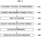
- FIG. 9 is a flowchart representing a method for evaluating insulation according to the present disclosure.
- the cell C which is a target to be tested, is placed on the fixing device 110.
- the cell C is firmly fixed using fastening members provided in the fixing device 110 at S10.
- the measurement probes 130 of the measurement module 120 are connected to the aluminum layer 44 and either positive electrode tab 22 or the negative electrode tab 23, respectively at S20.
- the measurement probes 130 may come into contact with the aluminum layer 44 by piercing the gas chamber, or may come into contact with the aluminum layer 44 exposed from the end of the packing material 40.
- the signal generator 140 of the measurement module 120 applies AC voltage to the cell C connected to the measurement module 120 at S30.
- AC voltage is applied to the cell C while changing a frequency from a high frequency value to a low frequency value.
- the measurement module 120 collects output signals in response to the applied AC voltage.
- the controller 160 analyzes the output signals at S40.
- the controller 160 calculates impedance based on the output signals at S50, visualizes the calculated impedance as a Bode plot, a Nyquist plot, etc. at S60.
- the controller 160 provides these plots to a user through the output unit 180. That is, as results of frequency response analysis, when the phase angle of the impedance is close to 90° as the frequency is changed from the high frequency value to the low frequency value, the corresponding cell C may be determined as a normal cell. On the contrary, when the phase angle of the impedance converges onto a value below 90°, e.g., any value between 0 to 85°, as the frequency is changed from the high frequency value to the low frequency value, the corresponding cell C may be determined as a cell in which insulation breaks down.
- a pouch-type cell is described as one example, but the apparatus for evaluating insulation according to the present disclosure may be applied not only to pouch-type cells but also to prismatic-type cells, and cylindrical-type cells.
- the apparatus for evaluating insulation according to the present disclosure secures data as impedance using AC voltage, thereby being capable of increasing reliability of a resistance value.
- the apparatus for evaluating insulation according to the present disclosure may integrate the conventional insulation voltage and insulation resistance measurement apparatuses into one unit, thereby being capable of reducing costs and improving productivity.
- data may be measured immediately after assembly of a secondary battery or after use of the secondary battery for a certain period of time.
- the present disclosure may provide an apparatus for evaluating insulation of a secondary battery which has improved measurement reliability using AC voltage.
- the present disclosure may provide an apparatus for evaluating insulation of a secondary battery which may simplify the conventional inspection apparatuses so as to reduce costs and to improve productivity.
Applications Claiming Priority (1)
| Application Number | Priority Date | Filing Date | Title |
|---|---|---|---|
| KR1020220089145A KR20240011935A (ko) | 2022-07-19 | 2022-07-19 | 이차전지의 절연 평가장치 |
Publications (1)
| Publication Number | Publication Date |
|---|---|
| EP4310525A1 true EP4310525A1 (en) | 2024-01-24 |
Family
ID=84463029
Family Applications (1)
| Application Number | Title | Priority Date | Filing Date |
|---|---|---|---|
| EP22212229.3A Pending EP4310525A1 (en) | 2022-07-19 | 2022-12-08 | Apparatus for evaluating insulation of secondary battery |
Country Status (5)
| Country | Link |
|---|---|
| US (1) | US20240030504A1 (ja) |
| EP (1) | EP4310525A1 (ja) |
| JP (1) | JP2024013182A (ja) |
| KR (1) | KR20240011935A (ja) |
| CN (1) | CN117420390A (ja) |
Citations (6)
| Publication number | Priority date | Publication date | Assignee | Title |
|---|---|---|---|---|
| JP2008243439A (ja) * | 2007-03-26 | 2008-10-09 | Nissan Motor Co Ltd | 電池の異常検出装置および電池の異常検出方法 |
| US20120019256A1 (en) * | 2008-10-13 | 2012-01-26 | Lg Chem, Ltd. | Method and apparatus for checking insulation of pouch electric cell and probe for the same |
| US20150226782A1 (en) * | 2012-02-22 | 2015-08-13 | Renault S.A.S. | Method and system for estimating the insulation resistance between a battery and an electrical earth |
| US20190064284A1 (en) * | 2013-06-04 | 2019-02-28 | Battelle Energy Alliance, Llc | Apparatuses and methods for testing electrochemical cells by measuring frequency response |
| US20200249264A1 (en) * | 2019-02-05 | 2020-08-06 | Allegro Microsystems, Llc | Integrated circuit having insulation monitoring with frequency discrimination |
| US20210011092A1 (en) * | 2019-07-08 | 2021-01-14 | Denso Corporation | Insulation resistance measuring apparatus |
-
2022
- 2022-07-19 KR KR1020220089145A patent/KR20240011935A/ko unknown
- 2022-12-07 US US18/076,562 patent/US20240030504A1/en active Pending
- 2022-12-08 EP EP22212229.3A patent/EP4310525A1/en active Pending
- 2022-12-13 JP JP2022198799A patent/JP2024013182A/ja active Pending
- 2022-12-30 CN CN202211730220.0A patent/CN117420390A/zh active Pending
Patent Citations (6)
| Publication number | Priority date | Publication date | Assignee | Title |
|---|---|---|---|---|
| JP2008243439A (ja) * | 2007-03-26 | 2008-10-09 | Nissan Motor Co Ltd | 電池の異常検出装置および電池の異常検出方法 |
| US20120019256A1 (en) * | 2008-10-13 | 2012-01-26 | Lg Chem, Ltd. | Method and apparatus for checking insulation of pouch electric cell and probe for the same |
| US20150226782A1 (en) * | 2012-02-22 | 2015-08-13 | Renault S.A.S. | Method and system for estimating the insulation resistance between a battery and an electrical earth |
| US20190064284A1 (en) * | 2013-06-04 | 2019-02-28 | Battelle Energy Alliance, Llc | Apparatuses and methods for testing electrochemical cells by measuring frequency response |
| US20200249264A1 (en) * | 2019-02-05 | 2020-08-06 | Allegro Microsystems, Llc | Integrated circuit having insulation monitoring with frequency discrimination |
| US20210011092A1 (en) * | 2019-07-08 | 2021-01-14 | Denso Corporation | Insulation resistance measuring apparatus |
Also Published As
| Publication number | Publication date |
|---|---|
| JP2024013182A (ja) | 2024-01-31 |
| KR20240011935A (ko) | 2024-01-29 |
| CN117420390A (zh) | 2024-01-19 |
| US20240030504A1 (en) | 2024-01-25 |
Similar Documents
| Publication | Publication Date | Title |
|---|---|---|
| Sood et al. | Health monitoring of lithium-ion batteries | |
| US11686699B2 (en) | System and method for anomaly detection and total capacity estimation of a battery | |
| JP4887581B2 (ja) | 電池の検査方法および検査装置 | |
| WO2004021498A1 (ja) | 二次電池前駆体の検査方法およびその検査装置ならびにその方法を用いた二次電池の製造方法 | |
| US20240036115A1 (en) | Battery diagnosing apparatus and method | |
| EP4310525A1 (en) | Apparatus for evaluating insulation of secondary battery | |
| JP3677993B2 (ja) | 電池の電極群の短絡検査方法及びその短絡検査装置 | |
| US20220381840A1 (en) | Big data-based battery inspection method | |
| EP4250466A1 (en) | Method for inspecting state of welds in battery | |
| CN115184823A (zh) | 二次电池的一致性检测方法 | |
| JP2021034348A (ja) | 蓄電デバイスの検査方法及び蓄電デバイスの製造方法 | |
| Christophersen | Battery state-of-health assessment using a near real-time impedance measurement technique under no-load and load conditions | |
| US20230152384A1 (en) | Method and device for testing a battery state in at least one battery | |
| Damlund | Analysis and interpretation of AC-measurements on batteries used to assess state-of-health and capacity-condition | |
| CN115079075A (zh) | 用于检验wat测试机台的测试结构及方法、测试系统 | |
| KR20180001351A (ko) | 납축전지 셀 간 전기적 및 물리적 쇼트 결함 검사방법 및 검사기 | |
| US20230160975A1 (en) | Device for inspecting for electrode assembly defects before electrolyte injection and defect inspection method therefor | |
| KR20220095730A (ko) | 와전류 센서를 이용한 전지 셀의 균열 검사 시스템 | |
| Savca et al. | Feasibility of eis on module level li-ion batteries for echelon utilization | |
| Tairov et al. | The novel method for estimating VRLA battery state of charge | |
| EP4279910A1 (en) | Apparatus for inspecting welds of battery module | |
| US20240142398A1 (en) | Welding inspection apparatus for battery modules | |
| JP2001076752A (ja) | 電池素子の検査装置及び検査方法 | |
| US20240012061A1 (en) | Method for evaluating a power storage device and method for producing the power storage device | |
| JP2004342476A (ja) | 二次電池の検査方法及び検査装置 |
Legal Events
| Date | Code | Title | Description |
|---|---|---|---|
| PUAI | Public reference made under article 153(3) epc to a published international application that has entered the european phase |
Free format text: ORIGINAL CODE: 0009012 |
|
| STAA | Information on the status of an ep patent application or granted ep patent |
Free format text: STATUS: THE APPLICATION HAS BEEN PUBLISHED |
|
| AK | Designated contracting states |
Kind code of ref document: A1 Designated state(s): AL AT BE BG CH CY CZ DE DK EE ES FI FR GB GR HR HU IE IS IT LI LT LU LV MC ME MK MT NL NO PL PT RO RS SE SI SK SM TR |
|
| P01 | Opt-out of the competence of the unified patent court (upc) registered |
Effective date: 20240125 |