EP4310331B1 - Fluidpumpenmodul - Google Patents
Fluidpumpenmodul Download PDFInfo
- Publication number
- EP4310331B1 EP4310331B1 EP22202680.9A EP22202680A EP4310331B1 EP 4310331 B1 EP4310331 B1 EP 4310331B1 EP 22202680 A EP22202680 A EP 22202680A EP 4310331 B1 EP4310331 B1 EP 4310331B1
- Authority
- EP
- European Patent Office
- Prior art keywords
- fluid
- inflow
- fluid pump
- frame body
- heat dissipation
- Prior art date
- Legal status (The legal status is an assumption and is not a legal conclusion. Google has not performed a legal analysis and makes no representation as to the accuracy of the status listed.)
- Active
Links
Images




Classifications
-
- F—MECHANICAL ENGINEERING; LIGHTING; HEATING; WEAPONS; BLASTING
- F04—POSITIVE - DISPLACEMENT MACHINES FOR LIQUIDS; PUMPS FOR LIQUIDS OR ELASTIC FLUIDS
- F04B—POSITIVE-DISPLACEMENT MACHINES FOR LIQUIDS; PUMPS
- F04B23/00—Pumping installations or systems
- F04B23/04—Combinations of two or more pumps
- F04B23/06—Combinations of two or more pumps the pumps being all of reciprocating positive-displacement type
-
- F—MECHANICAL ENGINEERING; LIGHTING; HEATING; WEAPONS; BLASTING
- F04—POSITIVE - DISPLACEMENT MACHINES FOR LIQUIDS; PUMPS FOR LIQUIDS OR ELASTIC FLUIDS
- F04B—POSITIVE-DISPLACEMENT MACHINES FOR LIQUIDS; PUMPS
- F04B43/00—Machines, pumps, or pumping installations having flexible working members
- F04B43/02—Machines, pumps, or pumping installations having flexible working members having plate-like flexible members, e.g. diaphragms
- F04B43/04—Pumps having electric drive
- F04B43/043—Micropumps
- F04B43/046—Micropumps with piezoelectric drive
-
- F—MECHANICAL ENGINEERING; LIGHTING; HEATING; WEAPONS; BLASTING
- F04—POSITIVE - DISPLACEMENT MACHINES FOR LIQUIDS; PUMPS FOR LIQUIDS OR ELASTIC FLUIDS
- F04B—POSITIVE-DISPLACEMENT MACHINES FOR LIQUIDS; PUMPS
- F04B49/00—Control, e.g. of pump delivery, or pump pressure of, or safety measures for, machines, pumps, or pumping installations, not otherwise provided for, or of interest apart from, groups F04B1/00 - F04B47/00
- F04B49/06—Control using electricity
-
- F—MECHANICAL ENGINEERING; LIGHTING; HEATING; WEAPONS; BLASTING
- F04—POSITIVE - DISPLACEMENT MACHINES FOR LIQUIDS; PUMPS FOR LIQUIDS OR ELASTIC FLUIDS
- F04B—POSITIVE-DISPLACEMENT MACHINES FOR LIQUIDS; PUMPS
- F04B53/00—Component parts, details or accessories not provided for in, or of interest apart from, groups F04B1/00 - F04B23/00 or F04B39/00 - F04B47/00
- F04B53/08—Cooling; Heating; Preventing freezing
-
- F—MECHANICAL ENGINEERING; LIGHTING; HEATING; WEAPONS; BLASTING
- F04—POSITIVE - DISPLACEMENT MACHINES FOR LIQUIDS; PUMPS FOR LIQUIDS OR ELASTIC FLUIDS
- F04B—POSITIVE-DISPLACEMENT MACHINES FOR LIQUIDS; PUMPS
- F04B53/00—Component parts, details or accessories not provided for in, or of interest apart from, groups F04B1/00 - F04B23/00 or F04B39/00 - F04B47/00
- F04B53/10—Valves; Arrangement of valves
- F04B53/102—Disc valves
-
- F—MECHANICAL ENGINEERING; LIGHTING; HEATING; WEAPONS; BLASTING
- F04—POSITIVE - DISPLACEMENT MACHINES FOR LIQUIDS; PUMPS FOR LIQUIDS OR ELASTIC FLUIDS
- F04B—POSITIVE-DISPLACEMENT MACHINES FOR LIQUIDS; PUMPS
- F04B53/00—Component parts, details or accessories not provided for in, or of interest apart from, groups F04B1/00 - F04B23/00 or F04B39/00 - F04B47/00
- F04B53/16—Casings; Cylinders; Cylinder liners or heads; Fluid connections
Definitions
- the present disclosure relates to a fluid pump module, and more particularly to a fluid pump module with a core module for transporting a fluid.
- the design of the structure for the fluid transportation device still has to consider some issues, such as heat dissipation, stability, endurance performance, and vibration suppression, of the micro pump itself during operation while maintaining a sufficient flow rate.
- the issues described above are even more important when the fluid transportation device is employed in the biomedical and healthcare applications since such issues mentioned above might significantly affect the using experience and the comfort level for the user.
- the structure of current commercial electric breast pump generally includes a breast suctioning shield, a breast milk collection bottle, a guiding tube, a driving pump, a control circuit and a battery.
- the power for the overall device is provided by the battery for operation.
- the breast suctioning shield is used by attaching to the breast of the user while a driving signal is transmitted from the control circuit to the driving pump to produce a suctioning force, and the breast milk can be guided to the breast milk collection bottle via the guiding tube for storage, thereby achieving the purpose of assisting the user in collecting the breast milk thereof.
- US 2021/324851 A1 describes a pump unit which includes a plurality of piezoelectric pumps, a flow path-defining member, and a heat-dissipating part.
- the plurality of piezoelectric pumps each include a first flow path for sucking and discharging of fluid.
- the flow path-defining member includes a second flow path for connection to the first flow paths in the plurality of piezoelectric pumps.
- Heat generated in the plurality of piezoelectric pumps is dissipated through the heat-dissipating part.
- the heat-dissipating part is disposed between the flow path-defining member and each of the plurality of piezoelectric pumps.
- the heat-dissipating part has through-holes through which the first flow paths are connected to the second flow path.
- JP 2016 200067 A relates to a fluid control device which comprises a piezoelectric pump, a valve, a cuff, a heat sink, and a control part.
- the valve comprises a first valve case provided with first vent holes and, and a second valve case provided with a second vent hole and a third vent hole.
- a manchette rubber tube of the cuff is fitted to the second vent hole of the valve, and the valve is thereby connected to the cuff.
- the piezoelectric pump comprises a pump case provided with discharge holes and. The first vent holes and of the valve are connected to the discharge holes and of the piezoelectric pump.
- the heat sink is fitted to a bottom surface of the pump case. The heat sink comprises an opposed part opposed to the third vent hole.
- the object of the present disclosure is to improve the efficacy of the conventional fluid pump, such as heat dissipation, stability, endurance performance, and vibration suppression, as being installed in the device utilizing the fluid pump while ensuring a sufficient flow supply of the fluid simultaneously.
- the fluid pump module described in the present disclosure can be installed in all kinds of devices utilizing the fluid pump, e.g., electric breast pumps, liquid filters, fluid filters, fresh air fans, hair dryers, in various fields, such as the industrial application, the biomedical application, the healthcare, and the electronic cooling.
- the above mentioned object is solved by a fluid pump module having the features of claim 1.
- the fluid pump module includes a heat dissipation board assembly, a fixing frame body, fluid pumps, a control board and a conveying pipe.
- the fixing frame body is fixed at one side of the heat dissipation board assembly, so as to form two accommodating spaces between the heat dissipation board assembly and the fixing frame body.
- Two fluid pumps are disposed in the two accommodating spaces respectively.
- the control board is disposed at another side of the heat dissipation board assembly.
- the conveying pipe connects with the two fluid pumps so as to form a series connection therebetween.
- the control board controls the operation of the fluid pumps, and the heat dissipation board assembly dissipates heats produced by a module formed by the two fluid pumps.
- the heat dissipation board assembly comprises a plurality of heat dissipation flat boards and a heat dissipation lateral board, wherein ends at the same side of the plurality of heat dissipation flat boards are connected with the heat dissipation lateral board, so as to form the two accommodating spaces between the heat dissipation board assembly and the fixing frame body.
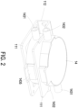
- the fluid pump module 1 includes a heat dissipation board assembly 11, a control board 12, a conveying pipe 13, two fluid pumps 14 and a fixing frame body 15.
- the heat dissipation board assembly 11 includes a plurality of heat dissipation flat boards 111 and a heat dissipation lateral board 112. In this embodiment, one end of each of the two heat dissipation flat boards 111 are both connected with the heat dissipation lateral board 112 to form a "C" shape structure.
- the heat dissipation board assembly 11 is made of a material with good thermal conductivity, such as metal.
- the fixing frame body 15 is fixed at one side of the heat dissipation board assembly 11, so as to form two accommodating spaces 113 between the heat dissipation board assembly 11 and the fixing frame body 15.
- the two fluid pumps 14 are respectively disposed in the two accommodating spaces 113 in a mirror symmetrical arrangement.
- One of the heat dissipation flat boards 111 is sandwiched between the two fluid pumps 14 so as to form a sandwich structure.
- the control board 12 is disposed at another side of the heat dissipation board assembly 11.
- the conveying pipe 13 connects and is in fluid communication with the two fluid pumps 14 so as to form a series connection therebetween.
- the control board 12 controls the operation of the two fluid pumps 14, and the heat dissipation board assembly 11 dissipates heats produced by a module formed by the two fluid pumps 14.
- the control board 12 may include, but not limited thereto, a processor, a memory, a temporary memory, a network communication module, a router, an I/O device, an operating system and/or an application program, which are electrically connected with each other through a known manner so as to perform the operation of calculation and storage, based on the practical requirements.
- the control board 12 transmits a driving signal for controlling the operation or the status of the fluid pump module 1 to a near remote end, so as to manage and coordinate the components of the fluid pump module 1.
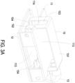
- each of the fluid pumps 14 has a flat cylindrical shape and includes a tubular disc 143, a core module 142 and a cover 141 which are sequentially stacked from bottom to top.
- the flowing path of the fluid pump 14 is accommodated in the tubular disc 143 for the fluid to flow in and out.
- the core module 142 is the power source for driving a fluid flow and is driven by the driving signal from the control board 12.
- the bottom surface of the cover 141 is combined with the top end of the tubular disc 143, so as to seal the core module 142 in the fluid pump 14.
- the fluid pump 14 since the fluid pump 14 has a flat cylindrical shape, when the two fluid pumps 14 are respectively disposed in the two accommodating spaces 113 in a mirror symmetrical arrangement to form a sandwich structure, in which one of the fluid pumps 14, one of the heat dissipation flat boards 111 and the other of the fluid pumps 14 are sequentially stacked from top to bottom, the contact areas of the cover 141 and the tubular disc 143 with the heat dissipation board assembly 11 can be maximized.
- the heat dissipation efficiency for the core module 142 in the fluid pump 14 can be optimized during operation, thereby avoiding the problem that the operation efficiency of the core module 142 is lowered due to the rising temperature derived from poor heat dissipation after the fluid pump 14 is operated for a period of time. Furthermore, in another aspect of the present disclosure, since the two fluid pumps 14 are arranged in a mirror symmetrical manner, when the two fluid pumps 14 are operating at the same time, the vibration peaks of one of the fluid pumps 14 can counteract the vibration valleys of the other of the fluid pumps 14, so as to make the operation of the fluid pump module 1 more stable which not only elongates the life time of the fluid pump module 1, but also reduces the power consumption of the fluid pumps 14 during operation.
- the fluid pump module 1 of the present disclosure is adapted to the healthcare and biochemical devices (such as the electric breast pump mentioned above) or other devices with special requirements with smooth operation, the good heat dissipation capability and the stable operation performance of the present fluid pumps 14 can also provide the user a better using experience, thereby achieving the purpose of improving the configuration of the conventional fluid transportation device while ensuring the sufficient fluid flow supplement.
- the fixing frame body 15 includes a frame body flat board 151, frame body side walls 152, frame body openings 153 and frame body fixing elements 154.
- the frame body flat board 151 is located at the top of the fixing frame body 15.
- the frame body side walls 152 are perpendicularly disposed at two opposite ends of the frame body flat board 151, and the frame body fixing elements 154 are disposed at ends of the frame body side walls 152 opposite to the frame body flat board 151, so as to form a " ⁇ " shape structure.
- the fixing frame body 15 is fixed on the heat dissipation board assembly 11 through engaging the frame body side walls 151 in indentations 114 provided at two opposite ends of the upper layer of the heat dissipation board assembly 11 and fixing the frame body fixing elements 154 located at the ends of the frame body side walls 152 on the lower layer of the heat dissipation board assembly 11, so as to form the accommodating spaces 113 for disposing the fluid pumps 14 therein.
- the frame body openings 153 are respectively provided on the frame body side walls 152 for allowing the conveying pipe 13 to extend out and serially connect the two fluid pumps 14.
- the optimal amount of the fluid pumps 14 is two, and accordingly, the fluid pump module 1 provides two accommodating spaces 113 in this embodiment.
- the amount of the fluid pumps 14 may be increased in accordance with the practical demands, and for accommodating more fluid pumps 14, the amount of the accommodating spaces 113 also may be increased through modifying the heat dissipation board assembly 11, for example, increasing the number of the heat dissipation flat boards 111 to provide more accommodating spaces 113 and thus accommodate more fluid pumps 14.
- the tubular disc 143 includes an inflow tube 1431, an outflow tube 1432 at the opposite side of the inflow tube 1431, and a protrusion portion 1435 located between the inflow tube 1431 and the outflow tube 1432.
- an inflow annular layer 1433 is disposed within the region surrounding by the inflow tube 1431, the outflow tube 1432 and the protrusion portion 1435.
- the inflow annular layer 1433 includes a notch which is in communication with the outflow tube 1432, and a fluid inlet 1438, which is in communication with the inflow tube 1431, is located at a position above the inflow annular layer 1433 opposite to the notch.
- an outflow annular layer 1434 is disposed within the inflow annular layer 1433.
- the outflow annular layer 1434 includes a fluid outlet 1437 which is in communication with the notch of the inflow annular layer 1433 and the outflow tube 1432.
- the protrusion portion 1435 of the tubular disc 143 includes a plurality of positioning latches 1436.
- the core module 142 includes a first electrode 1428 and a second electrode 1429, wherein the first electrode 1428 includes a first electrode positioning hole 1428A for engaging with one of the positioning latches 1436 on the protrusion portion 1435, and the second electrode 1429 includes a second electrode positioning hole 1429A for engaging with another positioning latch 1436 on the protrusion portion 1435.
- the cover 141 includes a first cover protrusion 1411 and a second cover protrusion 1412.
- the cover 141 is engaged and fixed with the tubular disc 143, so as to dispose the core module 142 between the tubular disc 143 and the cover 141, and the position of the first cover protrusion 1411 is corresponding to the fluid inlet 1438 and the position of the second cover protrusion 1412 is corresponding to the protrusion portion 1435.
- a total length of the fluid pump 14 without the inflow tube 1431 and the outflow tube 1432 is within a range of 28 mm ⁇ 10 mm
- a total width of the fluid pump 14 is within a range of 31 mm ⁇ 10 mm
- a thickness of the fluid pump 14 is within a range of 5 mm ⁇ 2 mm.
- an output pressure of the fluid pump 14 is within a range of 150 mmHg ⁇ 50 mmHg, and an output flow rate of the fluid pump 14 is within a range of 1000 ml/min ⁇ 300 ml/min.
- the total length, the total width and the total thickness of the fluid pump 14 and the lengths and diameters of the inflow tube 1431 and the outflow tube 1432 mentioned above are only illustrated as an example which can be modified based on the requirements of the device adopting the fluid pump 14 and are still within the scope of the present disclosure.
- the length of any one of the inflow tube 1431 and the outflow tube 1432 of the fluid pump 14 is equal to or less than 6 mm, and the diameter of any one of the inflow tube 1431 and the outflow tube 1432 of the fluid pump 14 is equal to or less than 5 mm.
- a hardness of the cover 141 of the fluid pump 14 is greater than 333MPa based on Brinell scale (according to the test standard in ISO2039-1).
- the material of the cover 141 is a heat conductive material or an aluminum alloy material.
- the hardness of the material of the cover 141 should be sufficient to resist the force caused by the vacuum formed during the fluid pump 14 is operating.
- the material of the cover 141 can be a metal material (such as the aluminum alloy).
- the metal material which is the heat conductive material provides a thermal conduction effect, so that the overall heat dissipation capability of the fluid pump 14 can be enhanced. A better heat dissipation capability for the fluid pump 14 is helpful for maintaining the performance of the fluid pump 14 at a desired level.
- the length of any one of the inflow tube 1431 and the outflow tube 1432 of the fluid pump 14 is equal to or more than 2.5 mm, and the diameter of any one of the inflow tube 1431 and the outflow tube 1432 of the fluid pump 14 is equal to or more than 2.5 mm.
- the hardness of the cover 141 of the fluid pump 14 is greater than 333MPa based on Brinell scale (according to the test standard in ISO2039-1).
- the material of the cover 141 is a heat conductive material or an aluminum alloy material.
- the hardness of the material of the cover 141 should be sufficient to resist the force caused by the vacuum formed during the fluid pump 14 is operating. If the hardness of the cover 141 is insufficient, the fluid pump 14 may collapse inwardly, thereby influencing the output efficacy of the fluid pump 14 and resulting in interferences and collisions between internal mechanisms of the fluid pump 14.
- the core module 142 includes a first electrode 1428 and a second electrode 1429.
- the first electrode 1428 includes a first electrode positioning hole 1428A for engaging and fixing on one of the positioning latches 1426 on the protrusion portion 1435 of the tubular disc 143.
- the second electrode 1429 includes a second electrode positioning hole 1429A for engaging and fixing on another positioning latch 1426 on the protrusion portion 1435 of the tubular disc 143.
- the protrusion portion 1435 of the tubular disc 143 is made of PC (Polycarbonate) material which is regarded as insulation material, thereby the first electrode 1428 and the second electrode 1429 would not short circuit.
- the core module 142 can be a fluid pump 14 or a piezoelectric fluid pump, but not limited thereto.
- the core module 142 can be any kind of pump capable of conveying the fluid without departing from the scope of the present disclosure.
- the cover 141 includes a first cover protrusion 1411 and a second cover protrusion 1412.
- the cover 141 is fixed and engaged with the tubular disc 143 so as to dispose the core module 142 between the tubular disc 143 and the cover 141.
- the first cover protrusion 1411 is correspondingly disposed at a position above the fluid inlet 1438
- the second cover protrusion 1412 is disposed at a position corresponding to the protrusion portion 1435.
- the fluid inlet 1438 is formed between the first cover protrusion 1411 of the cover 141 and the inflow annular layer 1433.
- the fluid inlet 1438 is located between the first cover protrusion 1411 and the core module 142, which is located above the inflow annular layer 1433, so that when the core module 142 is operating, the fluid is inhaled into the fluid pump 14 through the fluid inlet 1438 via the inflow tube 1431, is conveyed from a space above the core module 142 to a space below the core module 142, passes through the fluid outlet 1437 and the notch of the inflow annular layer 1433, and then is exhaled out of the fluid pump 14 through the outflow tube 1432.
- the second cover protrusion 1412 of the cover 141 is sealed with the protrusion portion 1435 of the tubular disc 143, the second cover protrusion 1412 does not contact with the first electrode 1428 and/or the second electrode 1429 of the core module 142, thereby preventing from short circuits therebetween.
- a sealant or an insulating glue also can be applied between the first electrode 1428 or the second electrode 1429 and the second cover protrusion 1412, so as to avoid the first electrode 1428 and/or the second electrode 1429 from contacting with the second cover protrusion 1412 and short circuits as the core module 142 is operating.
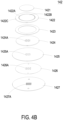
- FIG. 4B is a schematic exploded view showing the core module of the present disclosure.
- the core module 142 is encased by the cover 141 and the tubular disc 143 and driven by the control board 12 through a circuit loop formed by the first electrode 1428 and the second electrode 1429.
- the core module 142 includes a piezoelectric sheet 1421, an inflow plate 1422, a frame 1423, a second plate element 1424, a first plate element 1425, a valve sheet 1426 and an outflow plate 1427 which are sequentially stacked from top to bottom.
- the frame 1423 is disposed on the second plate element 1424, the second plate element 1424 is fixed on the first plate element 1425, the first plate element 1425 includes first through holes 1425A disposed thereon, the second plate element 1424 includes second through holes 1424A disposed thereon, and a thickness of the second plate element 1424 is greater than a thickness of the first plate element 1425.
- a plurality of second through holes 1424A are provided on the second plate element 1424 and a plurality of first through holes 1425A are provided on the first plate element 1425, and the amounts, positions, and diameters of the second through holes 1424A are corresponding to those of the first through holes 1425A.
- the diameter of the second through holes 1424A and the diameter of the first through holes 1425A are identical.
- the second plate element 1424 also includes a connection point (not shown) for electrically connecting with a conductive wire.
- the second plate element 1424 is a metal plate.
- the inflow plate 1422 includes a plurality of inflow apertures 1422A, and the inflow apertures 1422A are arranged in a shape on the plane of the inflow plate 1422. In an embodiment of the present disclosure, the inflow apertures 1422A are arranged in a circular shape. Through the arranged shape of the inflow apertures 1422A, an actuation region 1422B and a stationary region 1422C are respectively defined on the inflow plate 1422. The actuation region 1422B is enclosed by the inflow apertures 1422A and is driven by the deformation of the piezoelectric sheet 1421 to move upwardly and downwardly.
- the stationary region 1422C is outside the inflow apertures 1422A and is used to maintain the position of the inflow plate 1422 in the core module 142.
- Each of the inflow apertures 1422A mentioned above has a tapered shape for enhancing the inflow efficiency which is easy for flowing-in and difficult for flowing-out, so as to prevent the backflow of the fluid.
- the amount of the inflow apertures 1422A is even. In one of the embodiments, the amount of the inflow apertures 1422A is 48, and in another embodiment, the amount of the inflow apertures 1422A is 52, but not limited thereto.
- the arranged shape of the inflow apertures 1422A can be different, such as a rectangular shape, a square shape, or a circular shape, but not limited thereto.
- the piezoelectric sheet 1421 mentioned above has a shape of circular.
- the piezoelectric sheet 1421 is disposed on the actuation region 1422B of the inflow plate 1422 and the shape thereof is corresponding to the actuation region 1422B.
- the inflow apertures 1422A are arranged in a circular shape, so that the actuation region 1422B is defined as a circular shape, and the piezoelectric sheet 1421 also has a circular shape.
- the arranged shape of the inflow apertures 1422A can be rectangle, square or circle.
- the shape of the piezoelectric sheet 1421 should also be changed accordingly.
- the inflow apertures 1422A are arranged in a circular shape to match up with the piezoelectric sheet 1421 having a circular shape, and accordingly, the appearance of the core module 142 is also set up in a circular shape.
- the piezoelectric sheet 1421 when the piezoelectric sheet 1421 receives the driving signal (a driving voltage and a driving frequency), the electrical energy is converted into the mechanical energy through the converse piezoelectric effect, wherein a deformation level of the piezoelectric sheet 1421 is controlled by the level of the driving voltage, and a deformation frequency of the piezoelectric sheet 1421 is controlled by the driving frequency.
- the core module 142 is driven to convey the fluid through the deformation of the piezoelectric sheet 1421.
- the valve sheet 1426 is drawn upwardly to seal the first through holes 1425A of the first plate element 1425, and at this moment, the fluid is inhaled into the core module 142 through the inflow apertures 1422A. Then, when the piezoelectric sheet 1421 deforms again upon receiving the driving signal, the actuation region 1422B of the inflow plate 1422 is driven to bend downwardly, and the fluid in the core module 142 flows downwardly and passes through the second through holes 1424A of the second plate element 1424 and the first through holes 1425A of the first plate element 1425 at the same time.
- valve sheet 1426 is pushed and displaced through the motive energy of the downwardly flowed fluid, so that the valve sheet 1426 departs from the first through holes 1425A and abuts against the outflow plate 1427, thereby opening a flowing path and exhaling the fluid through an outflow aperture 1427A.
- the fluid pump 14 can achieve the effect of driving a large amount of fluid flow through driving the inflow plate 1422 to bend in a reciprocating manner by the piezoelectric sheet 1421.
- the effect of driving a large amount of fluid flow by the fluid pump 14 is achieved through sequentially disposed and stacked the piezoelectric sheet 1421, the inflow plate 1422, the frame 1423, the second plate element 1424, the first plate element 1425, the valve sheet 1426 and the outflow plate 1427.
- the fluid pumps 14 Furthermore, through arranging the fluid pumps 14 opposite to each other in a mirror symmetrical manner with the heat dissipation board assembly 11 disposed therebetween for fixing the fluid pumps 14 so as to form a sandwich structure sequentially stacking one of the fluid pumps 14, the heat dissipation board assembly 11 and the other fluid pump 14 from top to bottom, not only the heat produced by the fluid pump module 1 during operation can be effectively dissipated, the actuation procedure of the core module 142 also can be more stable. Therefore, the life time of the fluid pump module 1 can be elongated, and the power consumption of the fluid pumps 14 also can be reduced, thereby improving the devices adopting the technology of fluid transportation in the present disclosure in fields of industrial applications, biomedical applications, and healthcare.
Landscapes
- Engineering & Computer Science (AREA)
- Mechanical Engineering (AREA)
- General Engineering & Computer Science (AREA)
- Reciprocating Pumps (AREA)
- External Artificial Organs (AREA)
- Cooling Or The Like Of Electrical Apparatus (AREA)
- Details Of Reciprocating Pumps (AREA)
Claims (14)
- Fluidpumpenmodul (1), umfassend:eine Wärmeableitungsplattenbaugruppe (11);einen Befestigungsrahmenkörper (15), der an einer Seite der Wärmeableitungsplattenbaugruppe (11) befestigt ist, um zwischen der Wärmeableitungsplattenbaugruppe (11) und dem Befestigungsrahmenkörper (15) zwei Aufnahmeräume (113) zu bilden;zwei Fluidpumpen (14), die jeweils in den beiden Aufnahmeräumen (113) angeordnet sind;wobei die Wärmeableitungsplattenbaugruppe (11) Wärme ableitet, die von einem Modul erzeugt wird, das durch die beiden Fluidpumpen (14) gebildet wird,gekennzeichnet durch:eine Steuerschaltungsplatte (12), die an einer anderen Seite der Wärmeableitungsplattenbaugruppe (11) angeordnet ist; undein Förderrohr (13), das zwischen den beiden Fluidpumpen (14) angeschlossen ist, um die beiden Fluidpumpen (14) in Reihe zu verbinden, wobei die Steuerschaltungsplatte (12) den Betrieb der beiden Fluidpumpen (14) steuert,wobei die Wärmeableitungsplattenbaugruppe (11) eine Mehrzahl von flachen Wärmeableitungsplatten (111) und eine seitliche Wärmeableitungsplatte (112) umfasst, wobei Enden an der gleichen Seite der Mehrzahl von flachen Wärmeableitungsplatten (111) mit der seitlichen Wärmeableitungsplatte (112) verbunden sind, um zwischen der Wärmeableitungsplattenbaugruppe (11) und dem Befestigungsrahmenkörper (15) die beiden Aufnahmeräume (113) zu bilden.
- Fluidpumpenmodul (1) nach Anspruch 1, wobei die flache Wärmeableitungsplatte (111) zwischen den beiden Fluidpumpen (14) angeordnet ist und mit diesen in Kontakt steht, um eine Sandwich-Struktur zu bilden.
- Fluidpumpenmodul (1) nach Anspruch 1, wobei der Befestigungsrahmenkörper (15) ferner umfasst:eine flache Rahmenkörperplatte (151), Rahmenkörperseitenwände (152), Rahmenkörperöffnungen (153) und Rahmenkörperbefestigungselemente (154);wobei die flache Rahmenkörperplatte (151) an der Oberseite des Befestigungsrahmenkörpers (15) angeordnet ist, die Rahmenkörperseitenwände (152) senkrecht an zwei gegenüberliegenden Enden der flachen Rahmenkörperplatte (151) angeordnet sind, und die Rahmenkörperbefestigungselemente (154) an Enden der Rahmenkörperseitenwände (152) gegenüber der flachen Rahmenkörperplatte (151) angeordnet sind, wobei der Befestigungsrahmenkörper (15) in Vertiefungen an gegenüberliegenden Enden der Wärmeableitungsplattenbaugruppe (11) durch die Rahmenkörperseitenwände (152) befestigt ist, und die Rahmenkörperbefestigungselemente (154) an der Wärmeableitungsplattenbaugruppe (11) befestigt sind, so dass die zwei Fluidpumpen (14) in den Aufnahmeräumen (113) angeordnet sind, und wobei das Förderrohr (13) durch die Rahmenkörperöffnungen (153) verläuft, um mit den beiden Fluidpumpen (14) verbunden zu werden.
- Fluidpumpenmodul (1) nach Anspruch 1, wobei jede der Fluidpumpen (14) eine flache zylindrische Form hat und umfasst:eine rohrförmige Scheibe (143), ein Kernmodul (142) und eine Abdeckung (141);wobei die rohrförmige Scheibe (143), das Kernmodul (142) und die Abdeckung (141) sequentiell von unten nach oben gestapelt sind, die rohrförmige Scheibe (143) zur Aufnahme eines Strömungspfades der Fluidpumpe (14) vorgesehen ist, das Kernmodul (142) durch das Steuersignal angesteuert wird, das von der Steuerschaltungsplatte (12) empfangen wird, um einen Fluidstrom anzutreiben, und eine untere Fläche der Abdeckung (141) mit einem oberen Ende der rohrförmigen Scheibe (143) kombiniert ist, um das Kernmodul (142) in der Fluidpumpe (14) abzudichten.
- Fluidpumpenmodul (1) nach Anspruch 4, wobei die rohrförmige Scheibe (143) ferner umfasst:ein Einlassrohr (1431);ein Auslassrohr (1432), das an einer gegenüberliegenden Seite bezüglich des Einlassrohrs (1431) angeordnet ist; undeinen Vorsprungsbereich (1435), der sich zwischen dem Einlassrohr (1431) und dem Auslassrohr (1432) befindet,wobei eine ringförmige Einlassschicht (1433) in einer Region angeordnet ist, der von dem Einlassrohr (1431), dem Auslassrohr (1432) und dem Vorsprungsbereich (1435) umgeben ist, die ringförmige Einlassschicht (1433) eine Kerbe aufweist, die mit dem Auslassrohr (1432) in Verbindung steht, und ein Fluideinlass (1438) an einer Position über der ringförmigen Einlassschicht (1433) angeordnet ist und mit dem Einlassrohr (1431) in Verbindung steht;eine ringförmige Auslassschicht (1434), die innerhalb der ringförmigen Einlassschicht (1433) angeordnet ist, und die ringförmige Auslassschicht (1434) einen Fluidauslass (1437) umfasst, der mit dem Auslassrohr (1432) in Verbindung steht;der Vorsprungsbereich (1435) eine Mehrzahl von Positionierungsriegeln (1436) aufweist;das Kernmodul (142) eine erste Elektrode (1428) und eine zweite Elektrode (1429) aufweist, wobei die erste Elektrode (1428) ein erstes Elektrodenpositionierungsloch (1428A) zum Eingreifen und zum Befestigen mit einem der Positionierungsriegel (1436) aufweist, und wobei die zweite Elektrode (1429) ein zweites Elektrodenpositionierungsloch (1429A) zum Eingreifen und zum Befestigen mit einem anderen Positionierungsriegel (1436) an dem Vorsprungsbereich (1435) aufweist; unddie Abdeckung (141) einen ersten Abdeckungsvorsprung (1411) und einen zweiten Abdeckungsvorsprung (1412) aufweist, wobei, wenn die Abdeckung (141) mit der rohrförmigen Scheibe (143) in Eingriff steht und daran befestigt ist, der erste Abdeckungsvorsprung (1411) entsprechend über dem Fluideinlass (1438) angeordnet ist und der zweite Abdeckungsvorsprung (1412) entsprechend dem Vorsprungsbereich (1435) angeordnet ist.
- Fluidpumpenmodul (1) nach Anspruch 5, wobei eine Gesamtlänge der Fluidpumpe (14) ohne das Einlassrohr (1431) und das Auslassrohr (1432) innerhalb eines Bereichs von 28 mm ± 10 mm liegt, eine Gesamtbreite der Fluidpumpe (14) innerhalb eines Bereichs von 31 mm ± 10 mm liegt, und eine Dicke der Fluidpumpe (14) innerhalb eines Bereichs von 5 mm ± 2 mm liegt.
- Fluidpumpenmodul (1) nach Anspruch 5, wobei ein Ausgangsdruck der Fluidpumpe (14) innerhalb eines Bereichs von 150 mmHg ± 50 mmHg liegt, und eine Auslassströmungsrate der Fluidpumpe (14) innerhalb eines Bereichs von 1000 ml/min ± 300 ml/min liegt.
- Fluidpumpenmodul (1) nach Anspruch 5, wobei eine Länge von einem von dem Einlassrohr (1431) und dem Auslassrohr (1432) gleich oder kleiner als 6 mm ist, und ein Durchmesser von einem von dem Einlassrohr (1431) und dem Auslassrohr (1432) gleich oder kleiner als 5 mm ist.
- Fluidpumpenmodul (1) nach Anspruch 5, wobei eine Länge von einem von dem Einlassrohr (1431) und dem Auslassrohr (1432) gleich oder größer als 2,5 mm ist, und ein Durchmesser von einem von dem Einlassrohr (1431) und dem Auslassrohr (1432) gleich oder größer als 2,5 mm ist.
- Fluidpumpenmodul (1) nach Anspruch 4, wobei die Härte der Abdeckung (141) größer als 333 MPa auf der Brinell-Skala ist, und ein Material der Abdeckung (141) ein wärmeleitendes Material oder ein Aluminiumlegierungsmaterial ist.
- Fluidpumpenmodul (1) nach Anspruch 4, wobei das Kernmodul (142) ferner eine piezoelektrische Platte (1421), eine Einlassplatte (1422), einen Rahmen (1423), ein zweites Plattenelement (1424), ein erstes Plattenelement (1425), eine Ventilplatte (1426) und eine Auslassplatte (1427) aufweist, die sequentiell von oben nach unten gestapelt sind, und wobei der Rahmen (1423) auf dem zweiten Plattenelement (1424) angeordnet ist, das zweite Plattenelement (1424) an dem ersten Plattenelement (1425) befestigt ist, und eine Dicke des zweiten Plattenelements (1424) größer ist als eine Dicke des ersten Plattenelements (1425).
- Fluidpumpenmodul (1) nach Anspruch 11, wobei mindestens ein erstes Durchgangsloch (1425A) in dem ersten Plattenelement (1425) vorgesehen ist, mindestens ein zweites Durchgangsloch (1424A) in dem zweiten Plattenelement (1424) vorgesehen ist, und eine Anzahl, eine Position und ein Durchmesser von dem mindestens einen zweiten Durchgangsloch (1424A) denen von dem mindestens einen ersten Durchgangsloch (1425A) entsprechen.
- Fluidpumpenmodul (1) nach Anspruch 11, wobei die Einlassplatte (1422) eine Mehrzahl von Einlassöffnungen (1422A) aufweist, und die Mehrzahl von Einlassöffnungen (1422A) in einer Form auf einer Ebene der Einlassplatte (1422) angeordnet ist, wobei eine Region, die von der Mehrzahl von Einlassöffnungen (1422A) umschlossen ist, als eine Betätigungsregion (1422B) definiert ist, die durch Verformen der piezoelektrischen Platte (1421) betätigt wird, um sich nach oben und nach unten zu bewegen, und eine Region außerhalb der Einlassöffnungen (1422A) als eine stationäre Region (1422C) definiert ist, die verwendet wird, um die Einlassplatte (1422) in dem Kernmodul (142) anzuordnen, und wobei die Form, in der die Mehrzahl von Einlassöffnungen (1422A) angeordnet ist, eine solche ist, die aus der Gruppe ausgewählt ist, die ein Rechteck, ein Quadrat und einen Kreis umfasst.
- Fluidpumpenmodul (1) nach Anspruch 13, wobei, wenn die piezoelektrische Platte (1421) das Steuersignal zum Verformen empfängt und die Betätigungsregion (1422B) nach oben gebogen wird, die Ventilplatte (1426) nach oben gezogen wird, um das mindestens eine erste Durchgangsloch (1425A) abzudichten, und gleichzeitig das Fluid durch die Einlassöffnung (1422A) in das Kernmodul (142) eingesaugt wird, und, wenn die Betätigungsregion (1422B) nach unten gebogen wird, das Fluid nach unten strömt, um durch das mindestens eine zweite Durchgangsloch (1424A) und das mindestens eine erste Durchgangsloch (1425A) zu gelangen, die Ventilplatte (1426) drückt, um sie von dem mindestens einen ersten Durchgangsloch (1425A) zu entfernen, und durch eine Auslassöffnung (1427A) ausströmt.
Applications Claiming Priority (1)
| Application Number | Priority Date | Filing Date | Title |
|---|---|---|---|
| TW111126902A TWI817615B (zh) | 2022-07-18 | 2022-07-18 | 流體泵浦模組 |
Publications (2)
| Publication Number | Publication Date |
|---|---|
| EP4310331A1 EP4310331A1 (de) | 2024-01-24 |
| EP4310331B1 true EP4310331B1 (de) | 2025-05-14 |
Family
ID=83899542
Family Applications (1)
| Application Number | Title | Priority Date | Filing Date |
|---|---|---|---|
| EP22202680.9A Active EP4310331B1 (de) | 2022-07-18 | 2022-10-20 | Fluidpumpenmodul |
Country Status (4)
| Country | Link |
|---|---|
| US (1) | US12116993B2 (de) |
| EP (1) | EP4310331B1 (de) |
| CN (1) | CN117419034A (de) |
| TW (1) | TWI817615B (de) |
Family Cites Families (13)
| Publication number | Priority date | Publication date | Assignee | Title |
|---|---|---|---|---|
| WO2002022358A1 (en) * | 2000-09-18 | 2002-03-21 | Par Technologies, Llc. | Piezoelectric actuator and pump using same |
| US6754076B2 (en) * | 2002-10-30 | 2004-06-22 | International Business Machines Corporation | Stackable liquid cooling pump |
| JP4815398B2 (ja) * | 2007-07-04 | 2011-11-16 | アルプス電気株式会社 | ドライバ内蔵圧電ポンプ |
| FR2939482B1 (fr) * | 2008-12-10 | 2011-01-14 | Rowenta Werke Gmbh | Pompe piezoelectrique pour appareil electromenager |
| LT2930363T (lt) | 2014-04-10 | 2021-01-11 | Stichting Nationaal Lucht- En Ruimtevaart Laboratorium | Pjezoelektrinio siurblio konstrukcija ir joje esanti slėginė grandinė |
| TWM503225U (zh) | 2015-02-24 | 2015-06-21 | Sonison Baby Products Co Ltd | 一種提供多種供電驅動的電動吸乳器 |
| JP2016200067A (ja) * | 2015-04-10 | 2016-12-01 | 株式会社村田製作所 | 流体制御装置 |
| CN206571656U (zh) * | 2017-03-10 | 2017-10-20 | 广东捷成科创电子股份有限公司 | 一种叠合式多腔压电气泵 |
| CN111492142B (zh) * | 2017-12-22 | 2022-05-13 | 株式会社村田制作所 | 泵 |
| DE112020000737B4 (de) * | 2019-03-18 | 2023-05-25 | Murata Manufacturing Co., Ltd. | Pumpeneinheit |
| JP7197008B2 (ja) * | 2019-06-27 | 2022-12-27 | 株式会社村田製作所 | ポンプ装置 |
| CN112392698B (zh) * | 2019-08-14 | 2023-01-24 | 研能科技股份有限公司 | 微型泵 |
| TWI724630B (zh) | 2019-11-14 | 2021-04-11 | 薩摩亞商媽媽餵授權公司 | 電動吸乳器 |
-
2022
- 2022-07-18 TW TW111126902A patent/TWI817615B/zh active
- 2022-09-09 US US17/941,755 patent/US12116993B2/en active Active
- 2022-10-20 EP EP22202680.9A patent/EP4310331B1/de active Active
-
2023
- 2023-05-11 CN CN202310529107.4A patent/CN117419034A/zh active Pending
Also Published As
| Publication number | Publication date |
|---|---|
| US12116993B2 (en) | 2024-10-15 |
| CN117419034A (zh) | 2024-01-19 |
| US20240018957A1 (en) | 2024-01-18 |
| TW202405308A (zh) | 2024-02-01 |
| EP4310331A1 (de) | 2024-01-24 |
| TWI817615B (zh) | 2023-10-01 |
Similar Documents
| Publication | Publication Date | Title |
|---|---|---|
| EP3328176B1 (de) | Luftkühlungswärmeableitungsvorrichtung und system | |
| JP6590896B2 (ja) | 空冷放熱装置 | |
| JP6487994B2 (ja) | 空冷放熱装置 | |
| CN113115556B (zh) | 电子装置 | |
| US10199306B2 (en) | Air-cooling heat dissipation device | |
| TWM582533U (zh) | 微型壓電泵浦 | |
| EP3364452A1 (de) | Luftkühlungswärmeableitungsvorrichtung | |
| EP4310331A1 (de) | Fluidpumpenmodul | |
| US20210017976A1 (en) | Micro pump | |
| US20100002392A1 (en) | Assembled Heat Sink Structure | |
| CN210470133U (zh) | 一种功率管散热结构及控制器 | |
| CN120529565B (zh) | 基于壳体内壁沟槽结构的微型流体散热装置及电子设备 | |
| JP7691376B2 (ja) | ガス輸送装置 | |
| JP7602498B2 (ja) | ガス輸送装置 | |
| JP2014107362A (ja) | 電子デバイスの放熱装置および放熱方法 | |
| CN114980687A (zh) | 散热组件、壳体组件和电子设备 | |
| TWM542332U (zh) | 氣冷散熱裝置 | |
| CN223089502U (zh) | 一种用于集成式压电泵的阀组件 | |
| CN108463086B (zh) | 气冷散热装置 | |
| US20240264646A1 (en) | Electronic Device | |
| US11703045B2 (en) | Thin gas transportation device | |
| US20250244088A1 (en) | Piezoelectric heat dissipation device and electronic device | |
| TWM537784U (zh) | 氣冷散熱裝置 | |
| JP5982118B2 (ja) | マイクロダイヤフラムポンプ、その実装構造およびポンプ実装用基板 | |
| JP2009203979A (ja) | ドライバ内蔵圧電ポンプ |
Legal Events
| Date | Code | Title | Description |
|---|---|---|---|
| PUAI | Public reference made under article 153(3) epc to a published international application that has entered the european phase |
Free format text: ORIGINAL CODE: 0009012 |
|
| STAA | Information on the status of an ep patent application or granted ep patent |
Free format text: STATUS: THE APPLICATION HAS BEEN PUBLISHED |
|
| AK | Designated contracting states |
Kind code of ref document: A1 Designated state(s): AL AT BE BG CH CY CZ DE DK EE ES FI FR GB GR HR HU IE IS IT LI LT LU LV MC ME MK MT NL NO PL PT RO RS SE SI SK SM TR |
|
| STAA | Information on the status of an ep patent application or granted ep patent |
Free format text: STATUS: REQUEST FOR EXAMINATION WAS MADE |
|
| 17P | Request for examination filed |
Effective date: 20240715 |
|
| RBV | Designated contracting states (corrected) |
Designated state(s): AL AT BE BG CH CY CZ DE DK EE ES FI FR GB GR HR HU IE IS IT LI LT LU LV MC ME MK MT NL NO PL PT RO RS SE SI SK SM TR |
|
| GRAP | Despatch of communication of intention to grant a patent |
Free format text: ORIGINAL CODE: EPIDOSNIGR1 |
|
| STAA | Information on the status of an ep patent application or granted ep patent |
Free format text: STATUS: GRANT OF PATENT IS INTENDED |
|
| RIC1 | Information provided on ipc code assigned before grant |
Ipc: F04B 53/08 20060101ALI20250210BHEP Ipc: F04B 43/04 20060101AFI20250210BHEP |
|
| INTG | Intention to grant announced |
Effective date: 20250304 |
|
| GRAS | Grant fee paid |
Free format text: ORIGINAL CODE: EPIDOSNIGR3 |
|
| GRAA | (expected) grant |
Free format text: ORIGINAL CODE: 0009210 |
|
| STAA | Information on the status of an ep patent application or granted ep patent |
Free format text: STATUS: THE PATENT HAS BEEN GRANTED |
|
| P01 | Opt-out of the competence of the unified patent court (upc) registered |
Free format text: CASE NUMBER: APP_16073/2025 Effective date: 20250402 |
|
| AK | Designated contracting states |
Kind code of ref document: B1 Designated state(s): AL AT BE BG CH CY CZ DE DK EE ES FI FR GB GR HR HU IE IS IT LI LT LU LV MC ME MK MT NL NO PL PT RO RS SE SI SK SM TR |
|
| REG | Reference to a national code |
Ref country code: GB Ref legal event code: FG4D |
|
| REG | Reference to a national code |
Ref country code: CH Ref legal event code: EP |
|
| REG | Reference to a national code |
Ref country code: DE Ref legal event code: R096 Ref document number: 602022014589 Country of ref document: DE |
|
| REG | Reference to a national code |
Ref country code: IE Ref legal event code: FG4D |
|
| REG | Reference to a national code |
Ref country code: NL Ref legal event code: MP Effective date: 20250514 |
|
| PG25 | Lapsed in a contracting state [announced via postgrant information from national office to epo] |
Ref country code: PT Free format text: LAPSE BECAUSE OF FAILURE TO SUBMIT A TRANSLATION OF THE DESCRIPTION OR TO PAY THE FEE WITHIN THE PRESCRIBED TIME-LIMIT Effective date: 20250915 Ref country code: ES Free format text: LAPSE BECAUSE OF FAILURE TO SUBMIT A TRANSLATION OF THE DESCRIPTION OR TO PAY THE FEE WITHIN THE PRESCRIBED TIME-LIMIT Effective date: 20250514 Ref country code: FI Free format text: LAPSE BECAUSE OF FAILURE TO SUBMIT A TRANSLATION OF THE DESCRIPTION OR TO PAY THE FEE WITHIN THE PRESCRIBED TIME-LIMIT Effective date: 20250514 |
|
| REG | Reference to a national code |
Ref country code: LT Ref legal event code: MG9D |
|
| PG25 | Lapsed in a contracting state [announced via postgrant information from national office to epo] |
Ref country code: NO Free format text: LAPSE BECAUSE OF FAILURE TO SUBMIT A TRANSLATION OF THE DESCRIPTION OR TO PAY THE FEE WITHIN THE PRESCRIBED TIME-LIMIT Effective date: 20250814 Ref country code: GR Free format text: LAPSE BECAUSE OF FAILURE TO SUBMIT A TRANSLATION OF THE DESCRIPTION OR TO PAY THE FEE WITHIN THE PRESCRIBED TIME-LIMIT Effective date: 20250815 |
|
| PG25 | Lapsed in a contracting state [announced via postgrant information from national office to epo] |
Ref country code: NL Free format text: LAPSE BECAUSE OF FAILURE TO SUBMIT A TRANSLATION OF THE DESCRIPTION OR TO PAY THE FEE WITHIN THE PRESCRIBED TIME-LIMIT Effective date: 20250514 Ref country code: PL Free format text: LAPSE BECAUSE OF FAILURE TO SUBMIT A TRANSLATION OF THE DESCRIPTION OR TO PAY THE FEE WITHIN THE PRESCRIBED TIME-LIMIT Effective date: 20250514 |
|
| REG | Reference to a national code |
Ref country code: AT Ref legal event code: MK05 Ref document number: 1794974 Country of ref document: AT Kind code of ref document: T Effective date: 20250514 |
|
| PG25 | Lapsed in a contracting state [announced via postgrant information from national office to epo] |
Ref country code: BG Free format text: LAPSE BECAUSE OF FAILURE TO SUBMIT A TRANSLATION OF THE DESCRIPTION OR TO PAY THE FEE WITHIN THE PRESCRIBED TIME-LIMIT Effective date: 20250514 |
|
| PG25 | Lapsed in a contracting state [announced via postgrant information from national office to epo] |
Ref country code: HR Free format text: LAPSE BECAUSE OF FAILURE TO SUBMIT A TRANSLATION OF THE DESCRIPTION OR TO PAY THE FEE WITHIN THE PRESCRIBED TIME-LIMIT Effective date: 20250514 |
|
| PG25 | Lapsed in a contracting state [announced via postgrant information from national office to epo] |
Ref country code: AT Free format text: LAPSE BECAUSE OF FAILURE TO SUBMIT A TRANSLATION OF THE DESCRIPTION OR TO PAY THE FEE WITHIN THE PRESCRIBED TIME-LIMIT Effective date: 20250514 |
|
| PG25 | Lapsed in a contracting state [announced via postgrant information from national office to epo] |
Ref country code: RS Free format text: LAPSE BECAUSE OF FAILURE TO SUBMIT A TRANSLATION OF THE DESCRIPTION OR TO PAY THE FEE WITHIN THE PRESCRIBED TIME-LIMIT Effective date: 20250814 |
|
| PG25 | Lapsed in a contracting state [announced via postgrant information from national office to epo] |
Ref country code: IS Free format text: LAPSE BECAUSE OF FAILURE TO SUBMIT A TRANSLATION OF THE DESCRIPTION OR TO PAY THE FEE WITHIN THE PRESCRIBED TIME-LIMIT Effective date: 20250914 |
|
| PG25 | Lapsed in a contracting state [announced via postgrant information from national office to epo] |
Ref country code: LV Free format text: LAPSE BECAUSE OF FAILURE TO SUBMIT A TRANSLATION OF THE DESCRIPTION OR TO PAY THE FEE WITHIN THE PRESCRIBED TIME-LIMIT Effective date: 20250514 |
|
| PGFP | Annual fee paid to national office [announced via postgrant information from national office to epo] |
Ref country code: DE Payment date: 20250912 Year of fee payment: 4 |
|
| PG25 | Lapsed in a contracting state [announced via postgrant information from national office to epo] |
Ref country code: SM Free format text: LAPSE BECAUSE OF FAILURE TO SUBMIT A TRANSLATION OF THE DESCRIPTION OR TO PAY THE FEE WITHIN THE PRESCRIBED TIME-LIMIT Effective date: 20250514 Ref country code: DK Free format text: LAPSE BECAUSE OF FAILURE TO SUBMIT A TRANSLATION OF THE DESCRIPTION OR TO PAY THE FEE WITHIN THE PRESCRIBED TIME-LIMIT Effective date: 20250514 |
|
| PG25 | Lapsed in a contracting state [announced via postgrant information from national office to epo] |
Ref country code: CZ Free format text: LAPSE BECAUSE OF FAILURE TO SUBMIT A TRANSLATION OF THE DESCRIPTION OR TO PAY THE FEE WITHIN THE PRESCRIBED TIME-LIMIT Effective date: 20250514 |
|
| PG25 | Lapsed in a contracting state [announced via postgrant information from national office to epo] |
Ref country code: EE Free format text: LAPSE BECAUSE OF FAILURE TO SUBMIT A TRANSLATION OF THE DESCRIPTION OR TO PAY THE FEE WITHIN THE PRESCRIBED TIME-LIMIT Effective date: 20250514 |
|
| PG25 | Lapsed in a contracting state [announced via postgrant information from national office to epo] |
Ref country code: SK Free format text: LAPSE BECAUSE OF FAILURE TO SUBMIT A TRANSLATION OF THE DESCRIPTION OR TO PAY THE FEE WITHIN THE PRESCRIBED TIME-LIMIT Effective date: 20250514 |
|
| PG25 | Lapsed in a contracting state [announced via postgrant information from national office to epo] |
Ref country code: IT Free format text: LAPSE BECAUSE OF FAILURE TO SUBMIT A TRANSLATION OF THE DESCRIPTION OR TO PAY THE FEE WITHIN THE PRESCRIBED TIME-LIMIT Effective date: 20250514 |
|
| REG | Reference to a national code |
Ref country code: DE Ref legal event code: R097 Ref document number: 602022014589 Country of ref document: DE |
|
| PG25 | Lapsed in a contracting state [announced via postgrant information from national office to epo] |
Ref country code: RO Free format text: LAPSE BECAUSE OF FAILURE TO SUBMIT A TRANSLATION OF THE DESCRIPTION OR TO PAY THE FEE WITHIN THE PRESCRIBED TIME-LIMIT Effective date: 20250514 |
|
| PLBE | No opposition filed within time limit |
Free format text: ORIGINAL CODE: 0009261 |
|
| STAA | Information on the status of an ep patent application or granted ep patent |
Free format text: STATUS: NO OPPOSITION FILED WITHIN TIME LIMIT |
|
| REG | Reference to a national code |
Ref country code: CH Ref legal event code: L10 Free format text: ST27 STATUS EVENT CODE: U-0-0-L10-L00 (AS PROVIDED BY THE NATIONAL OFFICE) Effective date: 20260325 |
|
| 26N | No opposition filed |
Effective date: 20260217 |
|
| REG | Reference to a national code |
Ref country code: CH Ref legal event code: H13 Free format text: ST27 STATUS EVENT CODE: U-0-0-H10-H13 (AS PROVIDED BY THE NATIONAL OFFICE) Effective date: 20260527 |
|
| PG25 | Lapsed in a contracting state [announced via postgrant information from national office to epo] |
Ref country code: LU Free format text: LAPSE BECAUSE OF NON-PAYMENT OF DUE FEES Effective date: 20251020 |
|
| REG | Reference to a national code |
Ref country code: BE Ref legal event code: MM Effective date: 20251031 |
|
| PG25 | Lapsed in a contracting state [announced via postgrant information from national office to epo] |
Ref country code: LT Free format text: LAPSE BECAUSE OF FAILURE TO SUBMIT A TRANSLATION OF THE DESCRIPTION OR TO PAY THE FEE WITHIN THE PRESCRIBED TIME-LIMIT Effective date: 20250514 |
|
| PG25 | Lapsed in a contracting state [announced via postgrant information from national office to epo] |
Ref country code: MC Free format text: LAPSE BECAUSE OF FAILURE TO SUBMIT A TRANSLATION OF THE DESCRIPTION OR TO PAY THE FEE WITHIN THE PRESCRIBED TIME-LIMIT Effective date: 20250514 |
|
| PG25 | Lapsed in a contracting state [announced via postgrant information from national office to epo] |
Ref country code: BE Free format text: LAPSE BECAUSE OF NON-PAYMENT OF DUE FEES Effective date: 20251031 Ref country code: CH Free format text: LAPSE BECAUSE OF NON-PAYMENT OF DUE FEES Effective date: 20251031 |
|
| PG25 | Lapsed in a contracting state [announced via postgrant information from national office to epo] |
Ref country code: FR Free format text: LAPSE BECAUSE OF NON-PAYMENT OF DUE FEES Effective date: 20251031 |
|
| PG25 | Lapsed in a contracting state [announced via postgrant information from national office to epo] |
Ref country code: SE Free format text: LAPSE BECAUSE OF FAILURE TO SUBMIT A TRANSLATION OF THE DESCRIPTION OR TO PAY THE FEE WITHIN THE PRESCRIBED TIME-LIMIT Effective date: 20250514 |