EP4310033A1 - Dispositif de transport et d'orientation d'objets - Google Patents
Dispositif de transport et d'orientation d'objets Download PDFInfo
- Publication number
- EP4310033A1 EP4310033A1 EP23182586.0A EP23182586A EP4310033A1 EP 4310033 A1 EP4310033 A1 EP 4310033A1 EP 23182586 A EP23182586 A EP 23182586A EP 4310033 A1 EP4310033 A1 EP 4310033A1
- Authority
- EP
- European Patent Office
- Prior art keywords
- section
- conveyor
- acceleration
- objects
- braking effect
- Prior art date
- Legal status (The legal status is an assumption and is not a legal conclusion. Google has not performed a legal analysis and makes no representation as to the accuracy of the status listed.)
- Pending
Links
- 230000000694 effects Effects 0.000 claims description 64
- 230000001133 acceleration Effects 0.000 claims description 62
- 230000007704 transition Effects 0.000 description 12
- 238000012856 packing Methods 0.000 description 4
- 230000004888 barrier function Effects 0.000 description 3
- 230000008859 change Effects 0.000 description 2
- 238000005096 rolling process Methods 0.000 description 2
- 210000002023 somite Anatomy 0.000 description 2
- 230000004913 activation Effects 0.000 description 1
- 230000008901 benefit Effects 0.000 description 1
- 230000000903 blocking effect Effects 0.000 description 1
- 239000002783 friction material Substances 0.000 description 1
- 239000007788 liquid Substances 0.000 description 1
- 238000012423 maintenance Methods 0.000 description 1
- 230000007257 malfunction Effects 0.000 description 1
- 239000000463 material Substances 0.000 description 1
- 239000002184 metal Substances 0.000 description 1
- 230000003287 optical effect Effects 0.000 description 1
- 238000004806 packaging method and process Methods 0.000 description 1
- 239000004033 plastic Substances 0.000 description 1
Images


Classifications
-
- B—PERFORMING OPERATIONS; TRANSPORTING
- B65—CONVEYING; PACKING; STORING; HANDLING THIN OR FILAMENTARY MATERIAL
- B65G—TRANSPORT OR STORAGE DEVICES, e.g. CONVEYORS FOR LOADING OR TIPPING, SHOP CONVEYOR SYSTEMS OR PNEUMATIC TUBE CONVEYORS
- B65G47/00—Article or material-handling devices associated with conveyors; Methods employing such devices
- B65G47/34—Devices for discharging articles or materials from conveyor
- B65G47/46—Devices for discharging articles or materials from conveyor and distributing, e.g. automatically, to desired points
-
- B—PERFORMING OPERATIONS; TRANSPORTING
- B65—CONVEYING; PACKING; STORING; HANDLING THIN OR FILAMENTARY MATERIAL
- B65G—TRANSPORT OR STORAGE DEVICES, e.g. CONVEYORS FOR LOADING OR TIPPING, SHOP CONVEYOR SYSTEMS OR PNEUMATIC TUBE CONVEYORS
- B65G47/00—Article or material-handling devices associated with conveyors; Methods employing such devices
- B65G47/22—Devices influencing the relative position or the attitude of articles during transit by conveyors
- B65G47/24—Devices influencing the relative position or the attitude of articles during transit by conveyors orientating the articles
- B65G47/244—Devices influencing the relative position or the attitude of articles during transit by conveyors orientating the articles by turning them about an axis substantially perpendicular to the conveying plane
-
- B—PERFORMING OPERATIONS; TRANSPORTING
- B65—CONVEYING; PACKING; STORING; HANDLING THIN OR FILAMENTARY MATERIAL
- B65G—TRANSPORT OR STORAGE DEVICES, e.g. CONVEYORS FOR LOADING OR TIPPING, SHOP CONVEYOR SYSTEMS OR PNEUMATIC TUBE CONVEYORS
- B65G43/00—Control devices, e.g. for safety, warning or fault-correcting
- B65G43/08—Control devices operated by article or material being fed, conveyed or discharged
-
- B—PERFORMING OPERATIONS; TRANSPORTING
- B65—CONVEYING; PACKING; STORING; HANDLING THIN OR FILAMENTARY MATERIAL
- B65G—TRANSPORT OR STORAGE DEVICES, e.g. CONVEYORS FOR LOADING OR TIPPING, SHOP CONVEYOR SYSTEMS OR PNEUMATIC TUBE CONVEYORS
- B65G47/00—Article or material-handling devices associated with conveyors; Methods employing such devices
- B65G47/22—Devices influencing the relative position or the attitude of articles during transit by conveyors
- B65G47/24—Devices influencing the relative position or the attitude of articles during transit by conveyors orientating the articles
- B65G47/244—Devices influencing the relative position or the attitude of articles during transit by conveyors orientating the articles by turning them about an axis substantially perpendicular to the conveying plane
- B65G47/2445—Devices influencing the relative position or the attitude of articles during transit by conveyors orientating the articles by turning them about an axis substantially perpendicular to the conveying plane by means of at least two co-operating endless conveying elements
-
- B—PERFORMING OPERATIONS; TRANSPORTING
- B65—CONVEYING; PACKING; STORING; HANDLING THIN OR FILAMENTARY MATERIAL
- B65G—TRANSPORT OR STORAGE DEVICES, e.g. CONVEYORS FOR LOADING OR TIPPING, SHOP CONVEYOR SYSTEMS OR PNEUMATIC TUBE CONVEYORS
- B65G47/00—Article or material-handling devices associated with conveyors; Methods employing such devices
- B65G47/34—Devices for discharging articles or materials from conveyor
- B65G47/44—Arrangements or applications of hoppers or chutes
-
- B—PERFORMING OPERATIONS; TRANSPORTING
- B65—CONVEYING; PACKING; STORING; HANDLING THIN OR FILAMENTARY MATERIAL
- B65G—TRANSPORT OR STORAGE DEVICES, e.g. CONVEYORS FOR LOADING OR TIPPING, SHOP CONVEYOR SYSTEMS OR PNEUMATIC TUBE CONVEYORS
- B65G47/00—Article or material-handling devices associated with conveyors; Methods employing such devices
- B65G47/52—Devices for transferring articles or materials between conveyors i.e. discharging or feeding devices
- B65G47/68—Devices for transferring articles or materials between conveyors i.e. discharging or feeding devices adapted to receive articles arriving in one layer from one conveyor lane and to transfer them in individual layers to more than one conveyor lane or to one broader conveyor lane, or vice versa, e.g. combining the flows of articles conveyed by more than one conveyor
- B65G47/71—Devices for transferring articles or materials between conveyors i.e. discharging or feeding devices adapted to receive articles arriving in one layer from one conveyor lane and to transfer them in individual layers to more than one conveyor lane or to one broader conveyor lane, or vice versa, e.g. combining the flows of articles conveyed by more than one conveyor the articles being discharged or distributed to several distinct separate conveyors or to a broader conveyor lane
-
- B—PERFORMING OPERATIONS; TRANSPORTING
- B65—CONVEYING; PACKING; STORING; HANDLING THIN OR FILAMENTARY MATERIAL
- B65G—TRANSPORT OR STORAGE DEVICES, e.g. CONVEYORS FOR LOADING OR TIPPING, SHOP CONVEYOR SYSTEMS OR PNEUMATIC TUBE CONVEYORS
- B65G51/00—Conveying articles through pipes or tubes by fluid flow or pressure; Conveying articles over a flat surface, e.g. the base of a trough, by jets located in the surface
- B65G51/02—Directly conveying the articles, e.g. slips, sheets, stockings, containers or workpieces, by flowing gases
- B65G51/03—Directly conveying the articles, e.g. slips, sheets, stockings, containers or workpieces, by flowing gases over a flat surface or in troughs
Definitions
- the present invention relates to a device for transporting objects such as packages, parcels, general cargo or shipments.
- the present invention relates to a device which can be part of a sorter for sorting the objects.
- the objects are usually sorted in so-called sorters.
- the objects are sorted and assigned to individual so-called end points.
- the objects at a respective end point can then be further transported, reloaded or sorted again.
- it may also be necessary to increase the number of end locations.
- this requires an increased space requirement.
- the dimensions of these end points cannot be chosen to be arbitrarily small, since the dimensions of the end points are based on the size of the objects.
- the individual packages can be designed very differently and can therefore, for example, weigh between 10g and 32 kg.
- the shape and size also varies over a wide range, for example between 5 x 5 x 0.5 cm to 60 x 60 x 120 cm.
- packing bags are increasingly being used as the outer packaging of the packages, which results in further variability in the transport behavior of the packages.
- the movement speed of the packages in a sorter should be chosen as high as possible in order to achieve the highest possible throughput of packages.
- light packages and in particular packing bags can or must be actively promoted, as they may even be too light to be able to slide over roller conveyors, for example, due to their weight.
- the object of the present invention is therefore to create a device for transporting objects in which tilting/jamming of the objects is prevented and which can be designed to be compact.
- the task is solved by a device according to claim 1 and a sorter according to claim 19.
- the device according to the invention for conveying objects has a first conveying device, the objects being conveyed in a first conveying direction by means of the first conveying device.
- This can be the objects for example, packages, parcels, general cargo, shipments or the like.
- the invention is not limited to a specific type of object.
- the device has at least one second conveying device, which branches off from the first conveying device and conveys the objects in a second conveying direction, the second conveying direction being different from the first conveying direction.
- the second conveyor device has an alignment device for aligning the objects.
- the alignment device can extend over the entire width of the second conveyor device or only over a part. The objects are thus aligned by the alignment device, in particular by rotating the objects.
- the alignment device can ensure that the width is aligned perpendicular to the second conveying direction, in particular by rotating the objects.
- the width of the second conveyor device which depends on the maximum width of the objects to be conveyed, can be reduced, so that the space requirement of the second conveyor device can be reduced, in particular along the first conveyor device or in the width direction of the second conveyor device.
- the alignment ensures that the object is prevented from tilting during the transition of the object from the first conveyor device to the second conveyor device.
- the alignment device in the second conveyor device thus prevents tilting, which means that manual interventions in the end points can be reduced.
- the alignment device is arranged directly in the transition between the first conveyor device and the second conveyor device and thus at the beginning of the second conveyor device.
- the alignment device is arranged within the second conveyor device or at the end thereof.
- the second conveying device is preferably a slide.
- the second conveying device is inclined relative to the horizontal, so that the objects move in the direction of the second conveying direction essentially due to their weight.
- this is not necessarily limited to a sliding movement, but also includes other forms in which movement of the objects is made possible due to their weight, such as roller conveyors.
- the objects preferably weigh between 10 g and 32 kg.
- the objects have a maximum width of up to 600 mm and/or a maximum length of up to 1200 mm.
- width the smaller of this dimension
- length the larger of this dimension
- the alignment device is designed to align objects with different weights and/or different dimensions, so that the objects are transported to the removal point of the end point without jamming/misunderstanding.
- the length of the object on the first conveying device is aligned along the first conveying direction.
- the length of the object is aligned perpendicular to the first conveying direction, i.e. the width of the objects is aligned along the first conveying direction.
- the objects thus lie with the long side forward (in the conveying direction of the first conveyor device) so that they can be thrown directly to the right or left into a respective end point without further rotation.
- the width of the object is along aligned with the second conveying direction, wherein the alignment device is designed to align the object so that after the alignment device the length of the object is aligned along the second conveying direction.
- the width of the second conveyor device is less than 1000 mm, preferably less than 800 mm and particularly preferably less than 650 mm. Alternatively or in addition to this, the width of the second conveyor device is less than the maximum length of the objects.
- the width of the second conveying device refers to the dimension of the second conveying device perpendicular to the second conveying direction. This can in particular be the minimum width of the second conveyor device.
- the second conveyor device can thus have a changing width, which is reduced, for example, starting from the first conveyor device in order to ensure an optimal transition of the objects from the first conveyor device to the second conveyor device.
- the first conveyor device is preferably a conveyor belt or a tilting tray conveyor.
- the second conveyor device is arranged essentially perpendicularly or inclined to the first conveyor device.
- the included angle between the first conveying direction and the second conveying direction is 90° or less, with the first conveying direction also being different from the second conveying direction.
- the alignment device is designed to align the objects depending on one or more properties, such as the weight of the object, the size of the object, in particular the length and/or width of the object, the position of the object on the first conveyor and the speed of the object on the first conveyor.
- the alignment device can thus be controlled in such a way that the alignment can be controlled depending on the weight, the size, the speed of the object and/or the position of the object on the first conveyor device and/or the orientation of the object on the first conveyor device and in order to thus ensuring optimal alignment of the objects during the transition from the first conveyor device to the second conveyor device.
- the alignment device has a first section and a second section, which are arranged next to one another along the second conveyor device.
- the first section and the second section are arranged one behind the other in a direction perpendicular to the second conveying direction.
- the first section and the second section can be arranged one behind the other in the first conveying direction.
- the first section is designed to brake the object with a first braking effect or to accelerate it with a first acceleration.
- the second section is designed to brake the object with a second braking effect or to accelerate it with a second acceleration.
- the first braking effect and the second braking effect are different from one another.
- the first acceleration and the second acceleration are different from each other. Due to the different accelerations or braking effects of the first section and the second section, the objects can be effectively aligned or rotated.
- a flat and in particular common conveying surface is formed by the first section and the second section.
- the first section and the second section are arranged at the same height and without a height offset.
- the object is preferably moved over the first section and at the same time over the second section and comes into contact with them, so that part of the object experiences the acceleration or braking effect of the first section and another part of the object experiences the acceleration or braking effect of the second section.
- different parts of the object are accelerated/decelerated differently, which leads to rotation and alignment of the object.
- the braking effect or the acceleration of the first section and/or the second section preferably takes place in the direction of movement/conveying direction of the second conveying device and not in the direction of movement/conveying direction of the first conveying device.
- the second conveyor device is designed as a slide, there is a superposition of the gravitational movement along the slide and the braking effect or acceleration of the first section and/or the second section for the alignment or rotation of the object.
- the second conveyor device preferably has a plurality of sections arranged next to one another, with a different braking effect or acceleration being generated by the respective sections and acting on the object to align or rotate the object.
- at least one section is designed according to the first section described above and at least one section is designed according to the second section described above.
- a boundary line between the first section and the second section can be arranged along the second conveying direction.
- the first section and the second section thus have a substantially equal width along the second conveying direction.
- the boundary line can differ from the second conveying direction, so that the first section and/or the second section changes along the second conveying direction.
- the width of the first section and/or the second section can change along the second conveying direction.
- the first section and the second section are the same width or different widths (i.e. in one dimension of the sections) and in particular the same size or different sizes (i.e. in terms of their area).
- the difference between the first braking effect and the second acceleration, the first braking effect and the second braking effect or the first acceleration and the second acceleration is determined depending on one or more of the size of the object, the weight of the object, the position of the object on the first conveyor, the orientation of the object on the first conveyor and the speed of the object on the first conveyor.
- a particularly heavy object can be accelerated more strongly in the first section in order to reduce the possibility of the object hitting the side wall of the second conveyor device.
- a higher weight also requires a greater acceleration and/or braking effect in order to ensure sufficient alignment of the heavy object within the length of the alignment device.
- a different acceleration can be selected for particularly light objects such as packing bags. The alignment device therefore prevents these light objects from remaining in place by actively accelerating the light object both in the first section and in the second section.
- the direction of movement of conveying elements of the first section is opposite to the second conveying direction.
- effective braking can be generated for a heavy object, for example, whereas for a light object the direction of movement of conveying elements is selected in the direction of the second conveying direction in order to actively convey the to ensure light object.
- the second conveyor device is designed as a slide, so that the movement of the object along this slide occurs essentially by the gravitational force.
- the first section and/or the second section are formed as roller conveyors.
- the roller conveyor has a large number of independently movable conveying elements over which the object is moved.
- the conveying elements can be, for example, rollers or balls. These conveying elements can be actively actuated, for example to generate an acceleration of the first section and/or the second section.
- it is a passive roller conveyor, wherein the movement resistance of the conveying elements of the first section and/or the second section can be adjusted, for example by a roller brake or the like.
- the first section and/or second section are formed as a conveyor belt or belt conveyor.
- the movement speed of the conveyor belt in the first section or in the second section can be selected accordingly.
- the movement of the object can, for example, be carried out essentially by the gravitational force, whereby the conveyor belts are only intended to ensure a corresponding alignment of the object.
- the first section and/or the second section is formed as a sliding surface.
- This is a passive alignment device that does not require activation and is therefore particularly simple and inexpensive to develop.
- the frictional resistance of the first section and/or the second section can be selected such that a different Braking effect is generated due to the friction of the object with the respective sliding surface of the first section and / or the second section to align the object.
- the first section and/or the second section is formed as an aerosurface (also referred to as a vacuum surface, air sheet/plate or the like), the aerosurface having a plurality of openings, the opening being able to be opened with an excess pressure to create an air cushion an object or can be subjected to negative pressure in order to press/suck the object onto the aerosurface.
- the aerosurface also referred to as a vacuum surface, air sheet/plate or the like
- the aerosurface having a plurality of openings, the opening being able to be opened with an excess pressure to create an air cushion an object or can be subjected to negative pressure in order to press/suck the object onto the aerosurface.
- the frictional resistance of the object across the aerosurface is reduced, thereby reducing the braking effect due to friction with the aerosurface.
- the object is sucked onto the aerosurface when a negative pressure is applied to the openings of the aerosurface, which increases the friction between the object and the aerosurface to increase the braking effect.
- the slipping properties of the objects can
- the first section and second section are preferably designed the same.
- the first section and the second section can be designed as a roller conveyor, as a conveyor belt, as a sliding surface and as an aerosurface, whereby a different acceleration and/or braking effect can be achieved due to the different design of the respective section.
- the roller conveyor or the conveyor belt of the first section can be moved independently of the roller conveyor or conveyor belt of the second section.
- the sliding surface of the first section has a different friction than the sliding surface of the second section.
- the first section and the second section are designed differently.
- the first section can be designed as a roller conveyor and the second section can be designed as a conveyor belt, sliding surface or aerosurface.
- the first section can be designed as a conveyor belt, whereas the second section is designed as a roller conveyor, sliding surface or aerosurface. Furthermore, the first section can be designed as a sliding surface, whereas the second section is designed as a roller conveyor, conveyor belt or aerosurface. Furthermore, the first section can be designed as an aerosurface, whereas the second section is designed as a roller conveyor, conveyor belt or sliding surface.
- the alignment device has a plurality of sections arranged next to one another, with at least two of these sections being formed as a first section and a second section as described above.
- the acceleration/braking effect is changed continuously from a first section to the adjacent section.
- a continuous change can take place from the first section to the second section.
- the acceleration/braking effect changes gradually when moving from one section to the adjacent section.
- the device preferably has a plurality of second conveying devices. Due to the present invention, the second conveying devices can be designed to be particularly space-saving by providing the alignment device, so that a large number of second conveying devices can be arranged next to one another in a space-saving manner.
- the device has a ejector which is assigned to the respective second conveyor devices and throws the objects from the first conveyor device into the second conveyor device.
- a corresponding number of ejectors can be provided.
- the present invention relates to a sorter with a device as described above.
- a sorter is a Logistics sorting and distribution system.
- the second conveying devices can be designed as end points of the sorter.
- the device 10 has a first conveying device 12, which conveys an object 16 along a first conveying direction 14.
- the object 16 can be, for example, a package, parcel, general cargo or the like.
- the first conveyor device 12 is a conveyor belt or tilting tray conveyor.
- the object 16 in the example Figure 1 has a width B and a length L. There is object 16 in the example Figure 1 with its length L aligned along the first conveying direction 14. Alternatively, the object 16 can be aligned on the first conveying device 12 with its width B along the first conveying direction 14.
- the device 10 has at least one second conveyor device 18.
- the second conveyor device 18 branches off from the first conveyor device 12. In the example of Figure 1 the second conveyor device 18 branches off essentially vertically from the first conveyor device 12. Other angles between the first conveyor 12 and the second conveyor 18 are also possible. Furthermore, in the example the Figure 1 only a second conveyor device 18 is shown. However, the device 10 can have a plurality of second conveying devices 18, which branch off along the first conveying direction 14 on one or both sides of the first conveying device 12. The number of second conveying devices is limited by their width and in particular their maximum width D, which in the example Figure 1 is present directly at the entrance or the transition from the first conveyor device 12 to the second conveyor device 18.
- the second conveyor device 18 can have a narrowing section 21, which provides guidance for dropped objects.
- the second conveying device 18 is designed to convey an object 22 in a second conveying direction 20.
- the object 16, which is conveyed by the first conveyor device can, for example, be dropped into the second conveyor device 18 and then transported by the second conveyor device 18.
- the second conveyor device is a slide, so that the object 16, which is thrown into the second conveyor device 18, moves along the second conveyor device 18 essentially by its weight.
- An additional movement component may be present by the discharge speed of the object from the first conveyor device onto the second conveyor device.
- the objects 16 can be very different and, for example, have a weight of between 10 g and 32 kg. Alternatively or additionally, the objects 16 can have a maximum width of up to 600 mm and/or a maximum length of up to 1200 mm.
- the alignment device 26 is designed to align objects 16 with different weights and/or different dimensions and different starting positions/orientations on the first conveyor device.
- the object 16 can tilt due to its dimensions during the transition from the first conveyor device 12 to the second conveyor device 18. This applies, in particular, if the length L of the object 16 is greater than the width D of the second conveyor device.
- the width D of the second conveyor device 18 is less than 1000 mm, preferably less than 800 mm and particularly preferably less than 650 mm. Alternatively or in addition to this, the width D of the second conveyor device 18 is less than the maximum length L of the objects 16.
- the second conveyor device 18 has an alignment device 26. If the object 16 is dropped from the first conveyor device 12 into the second conveyor device 18, the object 16 is aligned or rotated according to the arrow 24 by the alignment device 26. This is in Figure 1 represented by the rotated object 23, which is rotated into the second conveyor device 18. Since the width B of the object 16 is smaller than the length L, by appropriately aligning the object during the transition from the first conveying device 12 to the second conveying device 18, the object can be aligned in such a way that the width B is perpendicular to the second conveying direction 20.
- the alignment device can be used to align the objects 16 depending on the size of the object 16, the weight of the object 16, the speed of the object on the first conveyor 12 and/or the position of the object on the first conveyor. In this way, not only an optimal alignment of the object along the second conveying direction 20 can be achieved. A too hard impact on a side wall 19 of the second conveyor device can also be avoided by appropriate braking or redirection in the direction of the second conveying direction 20. At the same time, especially with light objects, a stay within the second conveyor device 18 can be avoided, which is particularly the case then can occur if the second conveyor device 18 is designed as a slide and the objects are particularly light objects such as packing bags. For this purpose, the alignment device 26 can be designed to accelerate the objects and thus provide active promotion, in particular of the light objects.
- a light barrier 32 which detects an object 16 which is thrown into the second conveyor device 18. As soon as such an object is detected by the light barrier 32, the object can be aligned using the alignment device 26.
- the light barrier 32 is only shown as an example. Additional sensors or alternative sensors may be used to detect the presence of an object, the size of the object, the weight of the object, the position and orientation of the object on the first conveyor and/or the speed of the Object on the first conveyor device to determine in order to control the alignment device 26 accordingly based on the parameters determined thereby. At least one of the sensors can be an optical sensor and in particular a camera.
- the object 16 thus rotates according to arrow 24 due to the different acceleration/deceleration of the object and the object 23 rotates.
- the braking effect or the acceleration of the first section 28 and/or the second section 30 takes place in the direction of movement/conveying direction of the second Conveyor device 18 and not in the direction of movement/conveyor device of the first conveyor device 12.
- first section 28 and the second section 30 form a flat and in particular common conveying surface over which the objects 16 are conveyed or slide.
- an object 16, which is moved over the first section 28 and the second section 30, can come into contact with the first section 28 and/or the second section 30 over as much of its surface as possible, so that the corresponding acceleration or braking effect of the respective section is effective be transferred to object 16.
- a desired rotation of the object 16 according to the arrow 24 is achieved in a simple manner.
- the object 16 moves simultaneously over the first section 28 and over the second section 30 and comes into contact with them, so that part of the object 16 experiences the acceleration or braking effect of the first section 28 and another part of the object 16 experiences the Acceleration or braking effect of the second section 30 experiences.
- different parts of the object 16 are accelerated/decelerated differently, which leads to a rotation and alignment of the object.
- Figure 2 shows a second conveyor device 18 with a first section 28 and a second section 30.
- the first section 28 is designed as a first sliding surface 36 and the second section 30 as a second sliding surface 34.
- the first sliding surface 36 and the second sliding surface 34 have different coefficients of friction, so that a different braking effect acts on the object when it slides over the sliding surfaces of the first section 28 and the second section 30. Due to the different braking effects, the object is aligned.
- the embodiment shown has the advantage that it can be designed to be passive, has no moving parts and is therefore simple and low-maintenance.
- the first section 28 can have lower friction than the second section 30, so that a corresponding alignment, as in Figure 1 shown is achieved.
- a second conveyor device 18 is shown.
- the second section 30 is designed as a second sliding surface 34 as in the Figure 2 described.
- the first section 28 is designed as a roller conveyor 36 with a large number of conveying elements.
- the conveying elements can be designed as rollers or rollers, which are rotatably mounted, or as ball elements (designed, for example, as roller conveyors), which are also rotatably mounted.
- the roller conveyor 36 can be active, ie actuated/controlled, so that the conveying elements are actively moved in order to thereby transmit an acceleration to the object 16.
- the roller conveyor 36 is a passive roller conveyor, which is not actuated or has no driven conveying elements.
- the rolling resistance of the roller conveyor 36 can be adjusted in order to transmit a suitable braking effect to the object and in particular to generate a selected braking effect in relation to the second section 30 in order to achieve an optimal alignment of the object.
- the rolling resistance of the rollers of the roller conveyor 36 can be adjusted, for example a braking element (based on friction, designed as an eddy current brake or the like) or can be generated, for example, by filling the individual roller elements with liquid.
- the surfaces of the roller elements can be formed, for example, by metal in order to achieve increased durability.
- the surfaces of the roller elements can be formed by a plastic or rubber in order to achieve a braking effect also in the direction of the first conveying direction 14 and thus to avoid an unintentionally hard impact on the side wall 19 of the second conveying device 18.
- the acceleration or braking effect of the roller conveyor 36 can be selected based on one or more of the parameters already discussed previously, such as size of the object, weight of the object, position of the object on the first conveyor device and speed of the object on the first conveyor device. As a result, the braking effect or the acceleration of the object in the first section 28 can be freely selected.
- Figure 4 shows a second conveyor device 18, the first section being designed as a first roller conveyor 38 as described in FIG Figure 3 .
- the second section 30 is designed as a second roller conveyor 40. This can also be designed as described above in connection with Figure 3 described.
- the acceleration or braking effect for the roller conveyor 40 of the second section can also be selected based on one or more of the parameters already discussed previously, such as size of the object, weight of the object, position of the object on the first conveyor device and speed of the object on the first conveyor device become.
- Figure 5 shows a second conveyor device 18, the second section 30 being designed as a roller conveyor 40, as in connection with Figures 3 and 4 described.
- the first section 28 is designed as a conveyor belt 42.
- the conveyor belt 42 accelerates the object in a controlled manner in order to align the object by the alignment device 26. Such an acceleration occurs if the conveying direction of the conveyor belt 42 is in the direction of the second conveying direction. Instead, the conveying direction of the conveyor belt 42 can be opposite to the second conveying direction 20, so that the object is effectively braked.
- the acceleration or braking effect of the conveyor belt 42 and/or the roller conveyor 40 can be selected based on one or more of the parameters already discussed previously, such as size of the object, weight of the object, position of the object on the first conveyor device and speed of the object on the first Conveyor device.
- the braking effect or the acceleration of the object in the first section 28 and in the second section 30 can be freely selected.
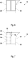
- Figure 6 shows a second conveyor device 18, the first section 28 being designed as a conveyor belt 42, as in connection with Figure 5 described.
- the second section 30 is also designed as a second conveyor belt 44, which can be moved independently of the conveyor belt 42 of the first section 28.
- the conveying speeds of the first conveyor belt 42 and the second conveyor belt 44 are different.
- the conveying directions of the first conveyor belt 42 and the second conveyor belt 44 are opposite in order to achieve an acceleration/deceleration of the object and thus an alignment of the object 16.
- the speeds of one or both conveyor belts 42, 44 can be selected based on one or more of the parameters already discussed previously, such as size of the object, weight of the object, position of the object on the first conveyor device and speed of the object on the first conveyor device.
- the braking effect or the acceleration of the object in the first section 28 and/or in the second section 30 can be freely selected.
- Figure 7 shows a second conveyor device 18, with a second section 30 being designed as a sliding surface 34, as in connection with Figures 2 and 3 described.
- the first section 28 is designed as an aerosurface 46.
- the aerosurface 46 has a plurality of openings/nozzles 48. These have a distance 50 in the transverse direction and a distance 52 in the longitudinal direction. This distance can be the same or different.
- the opening 48 can be pressurized so that an air cushion is formed under the object 16 when it slides over the aerosurface 46, whereby the friction between the object and the aerosurface 46 is reduced.
- the openings 48 are subjected to a negative pressure so that the object 16 is pressed onto the surface of the aerosurface, thereby increasing the friction between the object and the aerosurface 46.
- a surface 54 of the aerosurface 46 can be formed by a material with low friction.
- the surface 54 of the aerosurface 46 may be formed by a high friction material such as rubber, whereby the braking effect is further increased when a negative pressure is applied to the openings 48.
- the openings 48 can be designed as nozzles which point in a conveying direction, whereby an acceleration is applied to the object due to the direction of the nozzles.
- the excess pressure and/or negative pressure can be selected based on one or more of the parameters already discussed previously, such as size of the object, weight of the object, position of the object on the first conveyor device and speed of the object on the first conveyor device. As a result, the braking effect or the acceleration of the object in the first section 28 can be freely selected.
- Figure 8 shows a second conveyor device 18, the alignment device 26 in the first section and in the second section being designed as an aerosurface 54 with a plurality of openings 48.
- a negative pressure/overpressure can be applied to openings 48" of the first section.
- openings 48" of the second section can be subjected to an overpressure/negative pressure. In this way, a sectional acceleration/deceleration of the object on the alignment device 26 can be achieved, whereby an optimal alignment of the object 16 is achieved.
- Figure 9 shows a second conveyor device 18 with a plurality of sections 56.
- the sections can be designed as described above with reference to Figures 2-8 described.
- different acceleration/braking effects are generated by the sections 56, so that the object is optimally aligned and rotates in the direction of movement of the second conveyor device 18.
- the individual embodiments of the first section and/or the second section can be freely combined with one another.
- the different embodiments of the individual figures and in particular the Figures 1 and 9 together with the Figures 2 - 8 can be freely combined with each other.
- the alignment device 26 does not extend over the entire width D of the second conveyor device 18, but only occupies a part of it. Even if in the Figures 1 - 9 As it is shown that the alignment device 26 extends directly at the beginning of the second conveying device 18 starting in the direction of the second conveying direction 20, an area can initially be provided between the first conveying device 12 and the aligning device 26 into which the object can only be moved in the direction of the second conveying direction 20 is moved without alignment already taking place.
- the alignment device 26 can extend over the entire length of the second conveyor device 18 or be arranged at the end thereof.
- the first section and the second section are essentially the same size and are arranged unchanged from one another along the second conveying direction 20. This can be deviated from so that the first section, the second section or one the plurality of sections 56 can be of different sizes.
- the width D1 (shown in the Figure 2 ) and/or the width D2 (shown in the Figure 2 ) of the respective first section 28 or second section 30 vary along the second conveyor device 18 in order to achieve an optimal alignment.
- the present invention thus creates a device in which the objects to be conveyed are aligned. This means that tilting of the objects can be avoided during the transition from the first conveyor device to the second conveyor device.
- the objects can be aligned in such a way that the second conveyor device can be made compact, whereby the number of possible second conveyor devices can be increased in order to also increase the granularity of the sorting by the device. This can also be done for very different objects, which in particular have very different weights and/or very different sizes and properties. In this way, malfunctions in the device can be avoided.
- the weight of the object if the weight of the object is taken into account, heavy objects can be braked accordingly. This can prevent damage to these heavy objects caused by an impact that is too hard.
- Light objects on the other hand, can be accelerated, which can increase the throughput rate of objects of the device.
Landscapes
- Engineering & Computer Science (AREA)
- Mechanical Engineering (AREA)
- Physics & Mathematics (AREA)
- Fluid Mechanics (AREA)
- Attitude Control For Articles On Conveyors (AREA)
Applications Claiming Priority (1)
| Application Number | Priority Date | Filing Date | Title |
|---|---|---|---|
| DE102022116482.9A DE102022116482A1 (de) | 2022-07-01 | 2022-07-01 | Vorrichtung zum Befördern von Objekten |
Publications (1)
| Publication Number | Publication Date |
|---|---|
| EP4310033A1 true EP4310033A1 (fr) | 2024-01-24 |
Family
ID=87060444
Family Applications (1)
| Application Number | Title | Priority Date | Filing Date |
|---|---|---|---|
| EP23182586.0A Pending EP4310033A1 (fr) | 2022-07-01 | 2023-06-30 | Dispositif de transport et d'orientation d'objets |
Country Status (4)
| Country | Link |
|---|---|
| US (1) | US20240002169A1 (fr) |
| EP (1) | EP4310033A1 (fr) |
| CN (1) | CN117326303A (fr) |
| DE (1) | DE102022116482A1 (fr) |
Citations (3)
| Publication number | Priority date | Publication date | Assignee | Title |
|---|---|---|---|---|
| US4193489A (en) * | 1977-11-14 | 1980-03-18 | Rockwell International Corporation | Exit conveyor system for newspaper mail room |
| JP2001315928A (ja) * | 2000-05-10 | 2001-11-13 | Toyo Kanetsu Kk | 仕分装置のシュート構造 |
| US20190031450A1 (en) * | 2017-07-31 | 2019-01-31 | Dematic Corp. | Article sorter with active discharge |
Family Cites Families (5)
| Publication number | Priority date | Publication date | Assignee | Title |
|---|---|---|---|---|
| JPH0717267B2 (ja) | 1990-08-29 | 1995-03-01 | サンドビック株式会社 | 物品仕分け装置 |
| EP0727371B1 (fr) | 1995-02-14 | 2001-07-11 | Santrade Limited | Dispositif pour éliminer des articles transportés parallèlement à d'autres articles |
| DE502006007037D1 (de) | 2005-04-11 | 2010-07-08 | Siemens Ag | Fördereinrichtung mit mindestens einer rutsche für stückgüter und verfahren zum stapeln von stückgütern in einem behälter |
| US10059522B2 (en) | 2016-11-04 | 2018-08-28 | Laitram, L.L.C. | Divert chutes in sorting-conveyor systems |
| US11952220B2 (en) | 2019-04-29 | 2024-04-09 | Laitram, L.L.C. | Conveyor discharge with diverting rollers |
-
2022
- 2022-07-01 DE DE102022116482.9A patent/DE102022116482A1/de active Pending
-
2023
- 2023-06-29 US US18/215,902 patent/US20240002169A1/en active Pending
- 2023-06-29 CN CN202310778306.9A patent/CN117326303A/zh active Pending
- 2023-06-30 EP EP23182586.0A patent/EP4310033A1/fr active Pending
Patent Citations (3)
| Publication number | Priority date | Publication date | Assignee | Title |
|---|---|---|---|---|
| US4193489A (en) * | 1977-11-14 | 1980-03-18 | Rockwell International Corporation | Exit conveyor system for newspaper mail room |
| JP2001315928A (ja) * | 2000-05-10 | 2001-11-13 | Toyo Kanetsu Kk | 仕分装置のシュート構造 |
| US20190031450A1 (en) * | 2017-07-31 | 2019-01-31 | Dematic Corp. | Article sorter with active discharge |
Also Published As
| Publication number | Publication date |
|---|---|
| CN117326303A (zh) | 2024-01-02 |
| US20240002169A1 (en) | 2024-01-04 |
| DE102022116482A1 (de) | 2024-01-04 |
Similar Documents
| Publication | Publication Date | Title |
|---|---|---|
| DE3410287C2 (de) | Vorrichtung zum Ausschleusen von Papierstapeln an Papierverarbeitungsmaschinen | |
| DE102012009649B4 (de) | Greifvorrichtung | |
| EP0286080B1 (fr) | Dispositif pour diriger le transfert d'objets | |
| EP3115322B1 (fr) | Procede et dispositif destines a la depalettisation de pneus | |
| EP3080021B1 (fr) | Dispositif et procédé permettant de manipuler des objets | |
| EP1801047A2 (fr) | Dispositif de préhension pour des objets plats empilés | |
| EP1456101A1 (fr) | Procede et dispositif pour former des rangees d'articles empaquetes | |
| EP3786089A1 (fr) | Dispositif et procédé de transport et de tri des marchandises de détail | |
| EP0727370B1 (fr) | Installation de transport | |
| EP0619250B1 (fr) | Dispositif de transport pour produits disposés en couches | |
| DE19632224A1 (de) | Vorrichtung zum Ändern der Bewegungsrichtung von flachem, rechteckigen Blattgut | |
| EP4310033A1 (fr) | Dispositif de transport et d'orientation d'objets | |
| WO2017198768A2 (fr) | Transporteur-élévateur | |
| EP4302884A1 (fr) | Dispositif d'alignement d'objets | |
| EP4310032A1 (fr) | Dispositif d'alignement ou de positionnement. rotation d'objets avec une surface glissante | |
| EP2994402B1 (fr) | Manipulateur | |
| EP3623320A1 (fr) | Transporteur à rouleaux avec un frein ajustable | |
| EP4299485A1 (fr) | Dispositif d'alignement ou de positionnement. rotation d'objets | |
| CH699389B1 (de) | Zwischenspeichervorrichtung und Stapeleinheit mit Zwischenspeichervorrichtung. | |
| EP1851145B1 (fr) | Dispositif et procede d'acheminement cadence de produits en bois | |
| EP3744666A1 (fr) | Transport d'empilements de plateaux à l'aide d'une unité de désempilement | |
| AT517875B1 (de) | Kommissioniervorrichtung und Kommissionierlager | |
| DE19811166C2 (de) | Vorrichtung zum Vereinzeln flächiger Güter | |
| AT501825B1 (de) | Fördersystem zum fördern und vereinzeln von teilen | |
| AT3264U1 (de) | Förderstreckenanordnung für mit artikeln oder schüttgut zu befüllende behälter in einer füllstation |
Legal Events
| Date | Code | Title | Description |
|---|---|---|---|
| PUAI | Public reference made under article 153(3) epc to a published international application that has entered the european phase |
Free format text: ORIGINAL CODE: 0009012 |
|
| STAA | Information on the status of an ep patent application or granted ep patent |
Free format text: STATUS: THE APPLICATION HAS BEEN PUBLISHED |
|
| AK | Designated contracting states |
Kind code of ref document: A1 Designated state(s): AL AT BE BG CH CY CZ DE DK EE ES FI FR GB GR HR HU IE IS IT LI LT LU LV MC ME MK MT NL NO PL PT RO RS SE SI SK SM TR |
|
| STAA | Information on the status of an ep patent application or granted ep patent |
Free format text: STATUS: REQUEST FOR EXAMINATION WAS MADE |
|
| 17P | Request for examination filed |
Effective date: 20240221 |
|
| RBV | Designated contracting states (corrected) |
Designated state(s): AL AT BE BG CH CY CZ DE DK EE ES FI FR GB GR HR HU IE IS IT LI LT LU LV MC ME MK MT NL NO PL PT RO RS SE SI SK SM TR |