EP4308799B1 - Zentrier- und führungsvorrichtung für eine flugzeug-turbomaschinenwelle - Google Patents
Zentrier- und führungsvorrichtung für eine flugzeug-turbomaschinenwelle Download PDFInfo
- Publication number
- EP4308799B1 EP4308799B1 EP22713702.3A EP22713702A EP4308799B1 EP 4308799 B1 EP4308799 B1 EP 4308799B1 EP 22713702 A EP22713702 A EP 22713702A EP 4308799 B1 EP4308799 B1 EP 4308799B1
- Authority
- EP
- European Patent Office
- Prior art keywords
- axis
- openings
- support
- studs
- columns
- Prior art date
- Legal status (The legal status is an assumption and is not a legal conclusion. Google has not performed a legal analysis and makes no representation as to the accuracy of the status listed.)
- Active
Links
Images


Classifications
-
- F—MECHANICAL ENGINEERING; LIGHTING; HEATING; WEAPONS; BLASTING
- F02—COMBUSTION ENGINES; HOT-GAS OR COMBUSTION-PRODUCT ENGINE PLANTS
- F02C—GAS-TURBINE PLANTS; AIR INTAKES FOR JET-PROPULSION PLANTS; CONTROLLING FUEL SUPPLY IN AIR-BREATHING JET-PROPULSION PLANTS
- F02C7/00—Features, components parts, details or accessories, not provided for in, or of interest apart form groups F02C1/00 - F02C6/00; Air intakes for jet-propulsion plants
- F02C7/06—Arrangements of bearings; Lubricating
-
- F—MECHANICAL ENGINEERING; LIGHTING; HEATING; WEAPONS; BLASTING
- F01—MACHINES OR ENGINES IN GENERAL; ENGINE PLANTS IN GENERAL; STEAM ENGINES
- F01D—NON-POSITIVE DISPLACEMENT MACHINES OR ENGINES, e.g. STEAM TURBINES
- F01D25/00—Component parts, details, or accessories, not provided for in, or of interest apart from, other groups
- F01D25/16—Arrangement of bearings; Supporting or mounting bearings in casings
- F01D25/162—Bearing supports
- F01D25/164—Flexible supports; Vibration damping means associated with the bearing
-
- F—MECHANICAL ENGINEERING; LIGHTING; HEATING; WEAPONS; BLASTING
- F04—POSITIVE - DISPLACEMENT MACHINES FOR LIQUIDS; PUMPS FOR LIQUIDS OR ELASTIC FLUIDS
- F04D—NON-POSITIVE-DISPLACEMENT PUMPS
- F04D29/00—Details, component parts, or accessories
- F04D29/05—Shafts or bearings, or assemblies thereof, specially adapted for elastic fluid pumps
- F04D29/056—Bearings
- F04D29/059—Roller bearings
-
- F—MECHANICAL ENGINEERING; LIGHTING; HEATING; WEAPONS; BLASTING
- F16—ENGINEERING ELEMENTS AND UNITS; GENERAL MEASURES FOR PRODUCING AND MAINTAINING EFFECTIVE FUNCTIONING OF MACHINES OR INSTALLATIONS; THERMAL INSULATION IN GENERAL
- F16C—SHAFTS; FLEXIBLE SHAFTS; ELEMENTS OR CRANKSHAFT MECHANISMS; ROTARY BODIES OTHER THAN GEARING ELEMENTS; BEARINGS
- F16C27/00—Elastic or yielding bearings or bearing supports, for exclusively rotary movement
- F16C27/04—Ball or roller bearings, e.g. with resilient rolling bodies
- F16C27/045—Ball or roller bearings, e.g. with resilient rolling bodies with a fluid film, e.g. squeeze film damping
-
- F—MECHANICAL ENGINEERING; LIGHTING; HEATING; WEAPONS; BLASTING
- F16—ENGINEERING ELEMENTS AND UNITS; GENERAL MEASURES FOR PRODUCING AND MAINTAINING EFFECTIVE FUNCTIONING OF MACHINES OR INSTALLATIONS; THERMAL INSULATION IN GENERAL
- F16F—SPRINGS; SHOCK-ABSORBERS; MEANS FOR DAMPING VIBRATION
- F16F15/00—Suppression of vibrations in systems; Means or arrangements for avoiding or reducing out-of-balance forces, e.g. due to motion
- F16F15/02—Suppression of vibrations of non-rotating, e.g. reciprocating systems; Suppression of vibrations of rotating systems by use of members not moving with the rotating systems
- F16F15/023—Suppression of vibrations of non-rotating, e.g. reciprocating systems; Suppression of vibrations of rotating systems by use of members not moving with the rotating systems using fluid means
- F16F15/0237—Suppression of vibrations of non-rotating, e.g. reciprocating systems; Suppression of vibrations of rotating systems by use of members not moving with the rotating systems using fluid means involving squeeze-film damping
-
- F—MECHANICAL ENGINEERING; LIGHTING; HEATING; WEAPONS; BLASTING
- F05—INDEXING SCHEMES RELATING TO ENGINES OR PUMPS IN VARIOUS SUBCLASSES OF CLASSES F01-F04
- F05D—INDEXING SCHEME FOR ASPECTS RELATING TO NON-POSITIVE-DISPLACEMENT MACHINES OR ENGINES, GAS-TURBINES OR JET-PROPULSION PLANTS
- F05D2220/00—Application
- F05D2220/30—Application in turbines
- F05D2220/32—Application in turbines in gas turbines
- F05D2220/323—Application in turbines in gas turbines for aircraft propulsion, e.g. jet engines
-
- F—MECHANICAL ENGINEERING; LIGHTING; HEATING; WEAPONS; BLASTING
- F05—INDEXING SCHEMES RELATING TO ENGINES OR PUMPS IN VARIOUS SUBCLASSES OF CLASSES F01-F04
- F05D—INDEXING SCHEME FOR ASPECTS RELATING TO NON-POSITIVE-DISPLACEMENT MACHINES OR ENGINES, GAS-TURBINES OR JET-PROPULSION PLANTS
- F05D2240/00—Components
- F05D2240/50—Bearings
- F05D2240/54—Radial bearings
-
- F—MECHANICAL ENGINEERING; LIGHTING; HEATING; WEAPONS; BLASTING
- F05—INDEXING SCHEMES RELATING TO ENGINES OR PUMPS IN VARIOUS SUBCLASSES OF CLASSES F01-F04
- F05D—INDEXING SCHEME FOR ASPECTS RELATING TO NON-POSITIVE-DISPLACEMENT MACHINES OR ENGINES, GAS-TURBINES OR JET-PROPULSION PLANTS
- F05D2250/00—Geometry
- F05D2250/10—Two-dimensional
- F05D2250/14—Two-dimensional elliptical
-
- F—MECHANICAL ENGINEERING; LIGHTING; HEATING; WEAPONS; BLASTING
- F05—INDEXING SCHEMES RELATING TO ENGINES OR PUMPS IN VARIOUS SUBCLASSES OF CLASSES F01-F04
- F05D—INDEXING SCHEME FOR ASPECTS RELATING TO NON-POSITIVE-DISPLACEMENT MACHINES OR ENGINES, GAS-TURBINES OR JET-PROPULSION PLANTS
- F05D2260/00—Function
- F05D2260/30—Retaining components in desired mutual position
- F05D2260/31—Retaining bolts or nuts
-
- F—MECHANICAL ENGINEERING; LIGHTING; HEATING; WEAPONS; BLASTING
- F05—INDEXING SCHEMES RELATING TO ENGINES OR PUMPS IN VARIOUS SUBCLASSES OF CLASSES F01-F04
- F05D—INDEXING SCHEME FOR ASPECTS RELATING TO NON-POSITIVE-DISPLACEMENT MACHINES OR ENGINES, GAS-TURBINES OR JET-PROPULSION PLANTS
- F05D2260/00—Function
- F05D2260/96—Preventing, counteracting or reducing vibration or noise
-
- F—MECHANICAL ENGINEERING; LIGHTING; HEATING; WEAPONS; BLASTING
- F16—ENGINEERING ELEMENTS AND UNITS; GENERAL MEASURES FOR PRODUCING AND MAINTAINING EFFECTIVE FUNCTIONING OF MACHINES OR INSTALLATIONS; THERMAL INSULATION IN GENERAL
- F16C—SHAFTS; FLEXIBLE SHAFTS; ELEMENTS OR CRANKSHAFT MECHANISMS; ROTARY BODIES OTHER THAN GEARING ELEMENTS; BEARINGS
- F16C2360/00—Engines or pumps
- F16C2360/23—Gas turbine engines
Definitions
- the present invention relates to a device for centering and guiding an aircraft turbomachine shaft, as well as an aircraft turbomachine.
- An aircraft turbomachine comprises shafts, such as a low-pressure shaft and a high-pressure shaft, which are centered and guided in rotation by bearings, generally rolling bearings and for example roller or ball bearings.
- a rolling bearing comprises outer and inner rings between which the rollers or balls are arranged. The inner ring is integral with the shaft to be guided and the outer ring is fixed to a bearing support which is a rigid stator part of the turbomachine.
- a turbomachine shaft can reach a very high speed, typically between 2,000 and 30,000 revolutions per minute. Such speeds induce excitations of the shafts' natural modes which can have harmful effects on the engine if the mode responds strongly.
- the bearings are usually associated with flexible cages which allow the shaft boundary conditions to be relaxed and which lower the natural mode frequency. This can allow the mode to be lowered below the operating range.
- the term "flexible cage” means a member or assembly that provides a flexible connection between the outer ring of a bearing and its support.
- the flexibility of this cage is generally ensured by an elastic deformation capacity of this cage, for example in torsion and/or in bending.
- the cage comprises at least one series of columns distributed around the axis of the bearing and extending substantially parallel to this axis.
- a cage of this type comprises generally an inner cylindrical wall to which the outer ring of the bearing is fixed or integrated, and an outer cylindrical wall or flange for fixing to the bearing support.
- the walls are connected together by a series of generally C-shaped columns or two series of columns extending around each other and connected together. The columns and walls are then formed in one piece.
- a second technology described in the document FR-A1-3 009 843 relates to a cage obtained by assembling independent columns with the support and the ring.
- Each column comprises an elongated body connected to a first longitudinal end for fixing to the support and to a second longitudinal end for fixing to the ring.
- the body has a circular cross-sectional shape, i.e. an axisymmetric shape (the cross-sectional shape of the body of the column has a symmetry with respect to the longitudinal axis of this body).
- the flexible cage equipped with these columns also has an axisymmetric shape and its stiffness is identical regardless of the transverse direction of the stress forces on the cage.
- the state of the art also includes technologies described by FR-A1-3 091 902 , FR-A1-2 519 101 , GB-A-2 3100 258 , US-A1-2016/177765 , US-A-3 357 757 Or CN-B-103 244 276 .
- the invention proposes an improvement to this second technology, which in particular makes it possible to adapt the stiffness of the flexible cage depending on the direction of stress.
- a device according to the prior art equipped with columns with axisymmetric bodies has the same stiffness in all transverse directions (perpendicular to the axis).
- the invention makes it possible to give the device different stiffnesses according to the transverse directions of stress. Indeed, the clearances with different radial orientations between the columns and the openings of the support allow certain columns to respond differently to the stresses compared to other columns.
- the device comprises two different stiffnesses in transverse directions. It is indeed particularly interesting for stabilizing a shaft to provide different stiffnesses in two transverse directions perpendicular to each other because this makes it possible to delay the speed at which instabilities appear in the shaft guided by the device. Thanks to the formation of the flexible cage by assembling columns, the invention is advantageous because it allows a multitude of possible configurations while limiting the cost of the device. In the context of a single-block flexible cage by For example, a change in characteristics would involve the production of a new part. In the development phase, this would involve additional costs and delays, especially in the event of a dimensioning error in the prototype part. The production time for a new part would be incompressible.
- the invention covers all combinations of shapes for the cross sections of the columns and the openings of the support. These shapes can be chosen in a non-limiting manner from a general cylindrical, oblong, elliptical, rectangular or trapezoidal shape.
- the invention also relates to an aircraft turbomachine, comprising at least one device as described above.
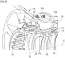
- FIG. 1 represents a first single-piece flexible cage technology 10 according to the prior art.
- the flexible cage 10 ensures the connection of an external ring 12 of a rolling bearing 14 to an annular support 16 of this bearing 14.
- the bearing 14 comprises, in addition to the outer ring 12, an inner ring 18 which is integral with a shaft of the turbomachine which is not shown.
- the rings 12, 18 define a roller raceway in the example shown.
- the external ring 12 is here integrated into an internal cylindrical wall 10a of the cage 10 which comprises a radially external annular flange 10b for fixing to the support 16 by screw-nut type means not shown.
- the cage 10 here comprises two series of columns 20, 22, respectively radially internal and external relative to the axis X of the bearing 14 and the shaft which it guides.
- the columns 20, 22 are distributed around the axis X and extend parallel to this axis.
- the columns 20 extend around the columns 22 and have a first of their longitudinal ends which is connected to the flange 10b, and a second of their longitudinal ends which is connected to the other columns 22 by an annular portion 24 with a C-section of the cage 10.
- the columns 22 extend from the wall 10a, in the extension thereof, to this portion 24.
- the support 16 is part of a stator of the turbomachine and here has a substantially truncated general shape. At its internal periphery, it comprises an internal cylindrical surface 16a for hooping a ring 26 which extends around the wall 10a of the cage and which defines with the latter an annular space 28 supplied with oil in order to form a film of oil for damping the vibrations transmitted by the bearing 14 in operation.
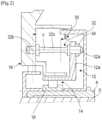
- FIG. 2 represents a second technology of flexible cage 30 with independent columns 32, according to the prior art.
- the flexible cage 30 also ensures the connection of an external ring 12 of a rolling bearing 14 to an annular support 16 of this bearing 14.
- the bearing 14 comprises, in addition to the outer ring 12, an inner ring 18 which is integral with a shaft A of the turbomachine.
- the rings 12, 18 define a roller raceway in the example shown.
- the outer ring 12 comprises a radially external annular flange 12a which comprises orifices crossed by ends 32a of the columns 32. These ends 32a are threaded and receive nuts 34 tightened against the flange 12a.
- the cage 30 here comprises a series of columns 32 which are distributed around the axis X and extend parallel to this axis.
- the columns 32 each comprise a body 32c which has a circular shape in section, and therefore symmetrical with respect to their axis Y.
- the columns 32 are also symmetrical with respect to each other with respect to the axis X.
- the flexible cage 30 is thus “axisymmetric”, and the stiffness of the cage 10 and the bearing 14 is therefore the same in all transverse directions (perpendicular to the X axis).
- this provides a stabilizing effect to the device by delaying the speed of appearance of instabilities due to the internal damping of the shaft.
- Control of shaft displacements according to azimuth can also be used to improve motor performance. Indeed, under mechanical or thermal loading the motor casing deforms, these distortions generate different clearance openings and closings according to the azimuth. This implies a degradation of the motor performance which could be limited if the dynamic displacement is optimized to compensate part of the distortion, for example by stiffening the flexible cage in the clearance closing direction and by softening it in the clearance opening direction.
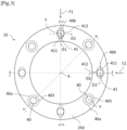
- Figures 3 to 6 illustrate an embodiment of a device, according to the invention, for centering and guiding an aircraft turbomachine shaft which makes it possible to meet this need.
- the third clearance 403 is preferably substantially greater than the first and second clearances 411, 412 and is oriented in the second radial direction D2 relative to the elongation axis Y.
- the first and second directions D1, D2 perpendicular to the axis X are preferably perpendicular to each other.
- the first direction D1 and the second direction D2 may be oriented tangentially or normally relative to a circumference centered on the main axis X.
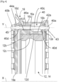
- the ring 12 has a general L-shape in axial section and comprises a cylindrical part 12b, one axial end of which is connected to a radially external annular flange 12a for fixing the columns 40, 41.
- the cylindrical part 12b of the ring 12 comprises at its internal periphery an annular groove 12c for rolling the balls of the bearing 14 and at its external periphery an external cylindrical surface 12d defining with the support 16 an annular space for forming a damping oil film.
- the support 16 is partially shown in the drawings.
- the support 16 comprises a first cylindrical wall 16b extending around the cylindrical part 12b of the ring 12 and comprising an internal cylindrical surface 16a defining with the surface 12d the aforementioned space for forming the damping oil film.
- the support 16 comprises a second cylindrical wall 16c extending around the first cylindrical wall 16b, or even also around the flange 12a of the ring 12.
- the first and second cylindrical walls 16b, 16c are connected to each other by the substantially radial annular wall 16d comprising the openings 46a, 46b crossed by the bodies 40c, 41c of the columns 40, 41.
- the columns 40, 41 cross an annular space formed between the walls 16b, 16c.
- the wall 16d is here located rather at an axial end of this space.
- the support 16 further comprises an annular flange 16e.
- the openings 46a, 46b comprise the first openings 46b which have a generally oblong or elliptical cross-section and the second openings 46a which have a generally circular cross-section.
- the first openings 46b may have an elongated shape, preferably in the same direction.
- the first openings 46b may have a generally circular cross-section and the second openings 46a may have a generally non-circular cross-section, for example oblong or elliptical.
- the column 40, 41 when the body 40c, 41c of non-cylindrical shape, for example oblong, of a column 40, 41 is engaged in one of the first openings 46b, of circular cross-section, the column 40, 41 may have a first positive clearance and a second quasi-zero clearance as described above.
- the body 40c, 41c of non-cylindrical shape, for example oblong, of a column 40, 41 is engaged in one of the second openings 46a, of non-circular cross-section, for example oblong, the column 40, 41 can have a third clearance substantially greater than the first and second clearances.
- the bodies 40c of the second columns 40 can pass through the second openings 46a of the annular wall 16d of the support 16 with a third clearance 403, as shown in the figure 4 which shows an axial sectional view of the device according to the cutting axis II drawn on the figure 3 .
- This third game 403 is oriented in all radial directions relative to the Y axis. It is understood that the openings 46a have a diameter greater than the diameter of the body 40c of the second columns 40.
- the bodies 41c of the first columns 41 can pass through the first openings 46b of the annular wall 16d of the support 16 with a first positive clearance 411 and a second almost zero clearance 412, as shown in the figure 5 And 6 which respectively show an axial sectional view of the device along the cutting axis II-II and the cutting axis III-III drawn on the figure 3 .
- the first positive 411 game visible on the figure 6 , is oriented in a first direction D1 radial with respect to the Y axis, this first direction D1 itself being oriented tangentially or normally with respect to a circumference centered on the X axis.
- the orifices 42a, 42b of the ring 12 and the orifices 44a, 44b of the support 16 have a generally circular cross-section. In this way, the ends 40a, 40b of the columns 40, 41 can be engaged without play in the ring 12 and in the support 16, as shown in the Figures 4 to 6 .
- each column 40, 41 may be connected to each of the ends 40a, 40b, 41a, 41b by annular collars 40d, 41d.
- the collars 40d, 41d may comprise a flat surface which may bear respectively on the flanges 16e, 12a of the support 16 and of the ring 12, in this way, the rotation of the columns 40, 41 about their longitudinal axis may be prevented.
- the device and the flexible cage according to the invention are thus advantageous insofar as the stiffness of the cage is different depending on the angular position of the force transmitted to the cage in a direction transverse to its main axis.
Landscapes
- Engineering & Computer Science (AREA)
- General Engineering & Computer Science (AREA)
- Mechanical Engineering (AREA)
- Chemical & Material Sciences (AREA)
- Combustion & Propulsion (AREA)
- Physics & Mathematics (AREA)
- Acoustics & Sound (AREA)
- Aviation & Aerospace Engineering (AREA)
- Support Of The Bearing (AREA)
Claims (11)
- Zentrier- und Führungsvorrichtung einer Flugfahrzeug-Turbotriebwerkswelle, wobei diese Vorrichtung beinhaltet:- einen externen Dichtungsring (12) eines Wälzlagers (14), wobei dieser Dichtungsring sich um eine Hauptachse (X) herum erstreckt und Bohrungen (42a, 42b) umfasst, die um diese Achse herum angeordnet und parallel zu dieser Achse orientiert sind,- eine ringförmige Lagerhalterung (16), die sich um die Hauptachse (X) und mindestens um den Dichtungsring (12) herum erstreckt, wobei diese Halterung Bohrungen (44a, 44b) und Öffnungen (46a, 46b) umfasst, die um diese Achse herum angeordnet und parallel zu dieser Achse orientiert sind, und- eine Reihe von Säulen (40, 41) zur Verbindung des Dichtungsrings mit der Halterung, wobei diese Säulen um die Hauptachse (X) herum verteilt sind und Verlängerungsachsen (Y) aufweisen, die im Wesentlichen parallel zu der Hauptachse (X) sind, wobei jede der Säulen einen Körper (40c, 41c) beinhaltet, umfassend ein erstes Längsende (40a, 41a) im Eingriff mit einer der Bohrungen (42a, 42b) des Dichtungsrings und ein zweites Längsende (40b, 41b) im Eingriff mit einer der Bohrungen (44a, 44b) der Halterung, wobei der Körper von jeder der Säulen eine der Öffnungen (46a, 46b) der Halterung durchquert,dadurch gekennzeichnet, dass gewisse der Säulen (40, 41), genannt erste Säulen (41), ihre Körper (41c) aufweisen, die die ersten Öffnungen mit einem ersten positiven Spielraum (411) und einem zweiten Spielraum (412) von quasi null durchqueren, wobei der erste Spielraum (411) in mindestens einer ersten radialen Richtung (D1) in Bezug auf die Verlängerungsachse (Y) orientiert ist und der zweite Spielraum (412) in mindestens einer zweiten radialen Richtung (D2), die sich von der ersten Richtung unterscheidet, in Bezug auf die Verlängerungsachse (Y) orientiert ist, wobei der erste und zweite Spielraum (411, 412) konfiguriert sind, damit die Vorrichtung Verschiebungsamplituden aufweist, die in mindestens zwei zur Hauptachse senkrechten Richtungen unterschiedlich sind.
- Vorrichtung nach dem vorstehenden Anspruch, wobei die erste und zweite Richtung (D1, D2) untereinander senkrecht sind.
- Vorrichtung nach einem der vorstehenden Ansprüche, wobei die erste Richtung (D1) und die zweite Richtung (D2) bezüglich eines auf der ersten Hauptachse (X) zentrierten Umfangs tangential oder normal orientiert sind.
- Vorrichtung nach einem der vorstehenden Ansprüche, wobei andere Säulen, genannt zweite Säulen (40) ihre Körper (40c) aufweisen, die die zweiten Öffnungen (46a) mit einem dritten Spielraum (403) durchqueren, der gemäß der zweiten Richtung orientiert ist, wobei sich der dritte Spielraum (403) von dem ersten und zweiten Spielraum (411, 412) der ersten Säulen (41) in den ersten Öffnungen (46b) unterscheidet und vorzugsweise größer ist.
- Vorrichtung nach dem vorstehenden Anspruch, wobei sich die ersten Säulen (41) mit den zweiten Säulen (40) um die Achse herum abwechseln.
- Vorrichtung nach einem der Ansprüche 4 oder 5, wobei die ersten Öffnungen (46b) im Querschnitt eine längliche Form oder eine elliptische Form aufweisen und die zweiten Öffnungen (46a) im Querschnitt eine kreisförmige Form aufweisen.
- Vorrichtung nach dem vorstehenden Anspruch, wobei die ersten Öffnungen (46b) derart orientiert sind, dass sie in einer gleichen Richtung eine langgestreckte Form präsentieren.
- Vorrichtung nach einem der vorstehenden Ansprüche, wobei die Körper (40c, 41c) im Querschnitt eine allgemein zylindrische Form aufweisen.
- Vorrichtung nach einem der vorstehenden Ansprüche, wobei die Öffnungen (46a, 46b) in einer ringförmigen Wand (16d) der Halterung (16) ausgebildet sind.
- Vorrichtung nach einem der vorstehenden Ansprüche, wobei der externe Dichtungsring (12) eine externe zylindrische Oberfläche (12d) umfasst, die mit einer internen zylindrischen Oberfläche (16a) der Halterung (16) einen ringförmigen Raum zur Bildung eines Dämpfungsölfilms definiert.
- Turbotriebwerk eines Luftfahrzeugs, das mindestens eine Vorrichtung nach einem der vorstehenden Ansprüche beinhaltet.
Applications Claiming Priority (2)
| Application Number | Priority Date | Filing Date | Title |
|---|---|---|---|
| FR2102710A FR3120900B1 (fr) | 2021-03-18 | 2021-03-18 | Dispositif de centrage et de guidage d’un arbre de turbomachine d’aeronef |
| PCT/FR2022/050411 WO2022195194A1 (fr) | 2021-03-18 | 2022-03-08 | Dispositif de centrage et de guidage d'un arbre de turbomachine d'aeronef |
Publications (2)
| Publication Number | Publication Date |
|---|---|
| EP4308799A1 EP4308799A1 (de) | 2024-01-24 |
| EP4308799B1 true EP4308799B1 (de) | 2024-11-20 |
Family
ID=75539633
Family Applications (1)
| Application Number | Title | Priority Date | Filing Date |
|---|---|---|---|
| EP22713702.3A Active EP4308799B1 (de) | 2021-03-18 | 2022-03-08 | Zentrier- und führungsvorrichtung für eine flugzeug-turbomaschinenwelle |
Country Status (5)
| Country | Link |
|---|---|
| US (1) | US12031448B2 (de) |
| EP (1) | EP4308799B1 (de) |
| CN (1) | CN117043448A (de) |
| FR (1) | FR3120900B1 (de) |
| WO (1) | WO2022195194A1 (de) |
Families Citing this family (2)
| Publication number | Priority date | Publication date | Assignee | Title |
|---|---|---|---|---|
| FR3120902B1 (fr) * | 2021-03-18 | 2023-03-10 | Safran Aircraft Engines | Dispositif de centrage et de guidage d’un arbre de turbomachine d’aeronef |
| DE102022124154A1 (de) * | 2022-09-20 | 2024-03-21 | Vibracoustic Se | Haltestruktur |
Family Cites Families (16)
| Publication number | Priority date | Publication date | Assignee | Title |
|---|---|---|---|---|
| GB988500A (en) * | 1964-02-21 | 1965-04-07 | Rolls Royce | Bearing |
| US4453783A (en) | 1981-12-28 | 1984-06-12 | United Technologies Corporation | Bearing support structure |
| GB2300258A (en) | 1995-04-28 | 1996-10-30 | Philip John Jewess | A separation device for magnetisable particles |
| DE19605971C2 (de) | 1996-02-17 | 1998-09-17 | Mtu Muenchen Gmbh | Lageranordnung für Drehkörper |
| US8573922B2 (en) * | 2010-06-15 | 2013-11-05 | Rolls-Royce Corporation | Bearing support |
| CN103244276B (zh) * | 2013-04-11 | 2015-09-09 | 北京航空航天大学 | 一种鼠笼式sma主动变刚度转子支承装置 |
| FR3009843B1 (fr) | 2013-08-26 | 2015-09-25 | Snecma | Colonnettes de support d'une bague exterieure de palier de roulement pour turbomachine d'aeronef, et procede de montage desdites colonnettes |
| US9783312B2 (en) * | 2014-07-10 | 2017-10-10 | Honeywell International Inc. | Method and apparatus for reducing high transient mount load in aircraft engine mounting systems |
| US10301957B2 (en) * | 2014-12-17 | 2019-05-28 | United Technologies Corporation | Pinned seal |
| US9841056B2 (en) * | 2015-10-21 | 2017-12-12 | General Electric Company | Bearing with drained race and squeeze film damper |
| US10823012B2 (en) * | 2016-05-20 | 2020-11-03 | Raytheon Technologies Corporation | Fastener openings for stress distribution |
| FR3078370B1 (fr) | 2018-02-28 | 2020-02-14 | Safran Helicopter Engines | Ensemble pour une turbomachine |
| FR3091902B1 (fr) * | 2019-01-23 | 2021-07-02 | Safran Aircraft Engines | Dispositif pour le centrage et le guidage en rotation d’un arbre de turbomachine comprenant plusieurs films fluides d’amortissement optimisés |
| US11174795B2 (en) * | 2019-11-26 | 2021-11-16 | Raytheon Technologies Corporation | Seal assembly with secondary retention feature |
| US11215077B1 (en) * | 2020-08-17 | 2022-01-04 | Raytheon Technologies Corporation | Integral gear support and bearing damper pedestal |
| US11512609B1 (en) * | 2021-06-30 | 2022-11-29 | Garrett Transportation I Inc | Turbomachine with housing control surfaces for aligning air bearing components |
-
2021
- 2021-03-18 FR FR2102710A patent/FR3120900B1/fr active Active
-
2022
- 2022-03-08 CN CN202280021242.1A patent/CN117043448A/zh active Pending
- 2022-03-08 EP EP22713702.3A patent/EP4308799B1/de active Active
- 2022-03-08 WO PCT/FR2022/050411 patent/WO2022195194A1/fr not_active Ceased
- 2022-03-08 US US18/549,794 patent/US12031448B2/en active Active
Also Published As
| Publication number | Publication date |
|---|---|
| EP4308799A1 (de) | 2024-01-24 |
| FR3120900B1 (fr) | 2023-02-10 |
| US12031448B2 (en) | 2024-07-09 |
| WO2022195194A1 (fr) | 2022-09-22 |
| CN117043448A (zh) | 2023-11-10 |
| US20240151159A1 (en) | 2024-05-09 |
| FR3120900A1 (fr) | 2022-09-23 |
Similar Documents
| Publication | Publication Date | Title |
|---|---|---|
| EP1769167B1 (de) | Pressfilmdämpfungsschicht mit mehreren dicken zwischen trägerkartusche und gehäuse | |
| EP4308800A1 (de) | Vorrichtung zur zentrierung und führung einer welle eines flugzeugturbinentriebwerks | |
| EP2365227B1 (de) | Verdreh- und Verschiebesicherung einer zweireihigen Kugellageranordnung im Gehäuse einer Turbomaschine mit flüssigkeitsgefülltem Dämpfungsspalt | |
| EP4308799B1 (de) | Zentrier- und führungsvorrichtung für eine flugzeug-turbomaschinenwelle | |
| EP3927617B1 (de) | Platzsparender und verstellbarer schaufelzapfen für turbomaschinen | |
| EP0109874B1 (de) | Montage eines Zwischenachslagers einer mehrstufigen Turbomaschine | |
| EP0335779A1 (de) | Spielkontrollvorrichtung einer Lagerung für koaxiale Wellen eines Mehrwellenstrahltriebwerks | |
| CA2776313A1 (fr) | Dispositif de centrage et de guidage en rotation d'un arbre de turbomachine | |
| FR2928682A1 (fr) | Configuration et procede de soutien d'enveloppe interieure de turbine. | |
| EP4034776B1 (de) | Turbomaschinengebläseanordnung mit einem rollenlager und einem zweireihigen kugellager mit schrägkontakt | |
| EP4308798B1 (de) | Zentrier- und führungsvorrichtung für eine flugzeug-turbomaschinenwelle | |
| WO2021214399A1 (fr) | Pivot d'aube à orientation réglable et à intégrité sauvegardée pour moyeu de soufflante de turbomachine | |
| EP2333365B1 (de) | Abstandshalter angepasster Länge für Wälzlager | |
| FR3120899A1 (fr) | Dispositif de centrage et de guidage d’un arbre de turbomachine d’aeronef | |
| FR3138806A1 (fr) | Helice pour une turbomachine d’aeronef | |
| EP3532732B1 (de) | Laufrad für kreiselpumpe, kreiselpumpe und herstellungsverfahren | |
| FR2871128A1 (fr) | Dispositif de colonne de direction et palier a roulement pour une telle colonne | |
| WO2017013359A1 (fr) | Assemblage d'une portion d'extrémité de vilebrequin avec un volant d'inertie et un palier de guidage, et ensemble moteur associé | |
| FR3103859A1 (fr) | Dispositif d’équilibrage | |
| WO2019053372A1 (fr) | Pivot pour palier lisse | |
| EP3976926B1 (de) | Turbomaschinenanordnung mit dämpfer | |
| EP4077958A1 (de) | Dreipunkt-kontaktwalzlager mit verbessertem abfluss | |
| FR3105320A1 (fr) | Palier de roulement mécanique à pistes en ogives | |
| FR3042215B1 (fr) | Structure pour turbomachine comportant des moyens de retention axiale de bague exterieure de palier de roulement | |
| FR3160221A1 (fr) | Palier à roulement à chemin de roulement asymétrique, notamment pour colonne de direction |
Legal Events
| Date | Code | Title | Description |
|---|---|---|---|
| STAA | Information on the status of an ep patent application or granted ep patent |
Free format text: STATUS: UNKNOWN |
|
| STAA | Information on the status of an ep patent application or granted ep patent |
Free format text: STATUS: THE INTERNATIONAL PUBLICATION HAS BEEN MADE |
|
| PUAI | Public reference made under article 153(3) epc to a published international application that has entered the european phase |
Free format text: ORIGINAL CODE: 0009012 |
|
| STAA | Information on the status of an ep patent application or granted ep patent |
Free format text: STATUS: REQUEST FOR EXAMINATION WAS MADE |
|
| 17P | Request for examination filed |
Effective date: 20230928 |
|
| AK | Designated contracting states |
Kind code of ref document: A1 Designated state(s): AL AT BE BG CH CY CZ DE DK EE ES FI FR GB GR HR HU IE IS IT LI LT LU LV MC MK MT NL NO PL PT RO RS SE SI SK SM TR |
|
| DAV | Request for validation of the european patent (deleted) | ||
| DAX | Request for extension of the european patent (deleted) | ||
| GRAP | Despatch of communication of intention to grant a patent |
Free format text: ORIGINAL CODE: EPIDOSNIGR1 |
|
| STAA | Information on the status of an ep patent application or granted ep patent |
Free format text: STATUS: GRANT OF PATENT IS INTENDED |
|
| INTG | Intention to grant announced |
Effective date: 20240820 |
|
| GRAS | Grant fee paid |
Free format text: ORIGINAL CODE: EPIDOSNIGR3 |
|
| GRAA | (expected) grant |
Free format text: ORIGINAL CODE: 0009210 |
|
| STAA | Information on the status of an ep patent application or granted ep patent |
Free format text: STATUS: THE PATENT HAS BEEN GRANTED |
|
| AK | Designated contracting states |
Kind code of ref document: B1 Designated state(s): AL AT BE BG CH CY CZ DE DK EE ES FI FR GB GR HR HU IE IS IT LI LT LU LV MC MK MT NL NO PL PT RO RS SE SI SK SM TR |
|
| REG | Reference to a national code |
Ref country code: GB Ref legal event code: FG4D Free format text: NOT ENGLISH |
|
| REG | Reference to a national code |
Ref country code: CH Ref legal event code: EP |
|
| REG | Reference to a national code |
Ref country code: DE Ref legal event code: R096 Ref document number: 602022007966 Country of ref document: DE |
|
| REG | Reference to a national code |
Ref country code: IE Ref legal event code: FG4D Free format text: LANGUAGE OF EP DOCUMENT: FRENCH |
|
| REG | Reference to a national code |
Ref country code: LT Ref legal event code: MG9D |
|
| REG | Reference to a national code |
Ref country code: NL Ref legal event code: MP Effective date: 20241120 |
|
| PG25 | Lapsed in a contracting state [announced via postgrant information from national office to epo] |
Ref country code: HR Free format text: LAPSE BECAUSE OF FAILURE TO SUBMIT A TRANSLATION OF THE DESCRIPTION OR TO PAY THE FEE WITHIN THE PRESCRIBED TIME-LIMIT Effective date: 20241120 Ref country code: IS Free format text: LAPSE BECAUSE OF FAILURE TO SUBMIT A TRANSLATION OF THE DESCRIPTION OR TO PAY THE FEE WITHIN THE PRESCRIBED TIME-LIMIT Effective date: 20250320 Ref country code: PT Free format text: LAPSE BECAUSE OF FAILURE TO SUBMIT A TRANSLATION OF THE DESCRIPTION OR TO PAY THE FEE WITHIN THE PRESCRIBED TIME-LIMIT Effective date: 20250320 |
|
| PGFP | Annual fee paid to national office [announced via postgrant information from national office to epo] |
Ref country code: DE Payment date: 20250218 Year of fee payment: 4 |
|
| PG25 | Lapsed in a contracting state [announced via postgrant information from national office to epo] |
Ref country code: NL Free format text: LAPSE BECAUSE OF FAILURE TO SUBMIT A TRANSLATION OF THE DESCRIPTION OR TO PAY THE FEE WITHIN THE PRESCRIBED TIME-LIMIT Effective date: 20241120 Ref country code: FI Free format text: LAPSE BECAUSE OF FAILURE TO SUBMIT A TRANSLATION OF THE DESCRIPTION OR TO PAY THE FEE WITHIN THE PRESCRIBED TIME-LIMIT Effective date: 20241120 |
|
| REG | Reference to a national code |
Ref country code: AT Ref legal event code: MK05 Ref document number: 1743750 Country of ref document: AT Kind code of ref document: T Effective date: 20241120 |
|
| PG25 | Lapsed in a contracting state [announced via postgrant information from national office to epo] |
Ref country code: BG Free format text: LAPSE BECAUSE OF FAILURE TO SUBMIT A TRANSLATION OF THE DESCRIPTION OR TO PAY THE FEE WITHIN THE PRESCRIBED TIME-LIMIT Effective date: 20241120 |
|
| PG25 | Lapsed in a contracting state [announced via postgrant information from national office to epo] |
Ref country code: ES Free format text: LAPSE BECAUSE OF FAILURE TO SUBMIT A TRANSLATION OF THE DESCRIPTION OR TO PAY THE FEE WITHIN THE PRESCRIBED TIME-LIMIT Effective date: 20241120 |
|
| PG25 | Lapsed in a contracting state [announced via postgrant information from national office to epo] |
Ref country code: NO Free format text: LAPSE BECAUSE OF FAILURE TO SUBMIT A TRANSLATION OF THE DESCRIPTION OR TO PAY THE FEE WITHIN THE PRESCRIBED TIME-LIMIT Effective date: 20250220 |
|
| PG25 | Lapsed in a contracting state [announced via postgrant information from national office to epo] |
Ref country code: GR Free format text: LAPSE BECAUSE OF FAILURE TO SUBMIT A TRANSLATION OF THE DESCRIPTION OR TO PAY THE FEE WITHIN THE PRESCRIBED TIME-LIMIT Effective date: 20250221 Ref country code: AT Free format text: LAPSE BECAUSE OF FAILURE TO SUBMIT A TRANSLATION OF THE DESCRIPTION OR TO PAY THE FEE WITHIN THE PRESCRIBED TIME-LIMIT Effective date: 20241120 Ref country code: LV Free format text: LAPSE BECAUSE OF FAILURE TO SUBMIT A TRANSLATION OF THE DESCRIPTION OR TO PAY THE FEE WITHIN THE PRESCRIBED TIME-LIMIT Effective date: 20241120 |
|
| PG25 | Lapsed in a contracting state [announced via postgrant information from national office to epo] |
Ref country code: PL Free format text: LAPSE BECAUSE OF FAILURE TO SUBMIT A TRANSLATION OF THE DESCRIPTION OR TO PAY THE FEE WITHIN THE PRESCRIBED TIME-LIMIT Effective date: 20241120 |
|
| PGFP | Annual fee paid to national office [announced via postgrant information from national office to epo] |
Ref country code: FR Payment date: 20250218 Year of fee payment: 4 |
|
| PG25 | Lapsed in a contracting state [announced via postgrant information from national office to epo] |
Ref country code: RS Free format text: LAPSE BECAUSE OF FAILURE TO SUBMIT A TRANSLATION OF THE DESCRIPTION OR TO PAY THE FEE WITHIN THE PRESCRIBED TIME-LIMIT Effective date: 20250220 |
|
| PG25 | Lapsed in a contracting state [announced via postgrant information from national office to epo] |
Ref country code: SM Free format text: LAPSE BECAUSE OF FAILURE TO SUBMIT A TRANSLATION OF THE DESCRIPTION OR TO PAY THE FEE WITHIN THE PRESCRIBED TIME-LIMIT Effective date: 20241120 |
|
| PG25 | Lapsed in a contracting state [announced via postgrant information from national office to epo] |
Ref country code: DK Free format text: LAPSE BECAUSE OF FAILURE TO SUBMIT A TRANSLATION OF THE DESCRIPTION OR TO PAY THE FEE WITHIN THE PRESCRIBED TIME-LIMIT Effective date: 20241120 |
|
| PG25 | Lapsed in a contracting state [announced via postgrant information from national office to epo] |
Ref country code: EE Free format text: LAPSE BECAUSE OF FAILURE TO SUBMIT A TRANSLATION OF THE DESCRIPTION OR TO PAY THE FEE WITHIN THE PRESCRIBED TIME-LIMIT Effective date: 20241120 |
|
| PG25 | Lapsed in a contracting state [announced via postgrant information from national office to epo] |
Ref country code: RO Free format text: LAPSE BECAUSE OF FAILURE TO SUBMIT A TRANSLATION OF THE DESCRIPTION OR TO PAY THE FEE WITHIN THE PRESCRIBED TIME-LIMIT Effective date: 20241120 |
|
| PG25 | Lapsed in a contracting state [announced via postgrant information from national office to epo] |
Ref country code: SK Free format text: LAPSE BECAUSE OF FAILURE TO SUBMIT A TRANSLATION OF THE DESCRIPTION OR TO PAY THE FEE WITHIN THE PRESCRIBED TIME-LIMIT Effective date: 20241120 |
|
| PG25 | Lapsed in a contracting state [announced via postgrant information from national office to epo] |
Ref country code: CZ Free format text: LAPSE BECAUSE OF FAILURE TO SUBMIT A TRANSLATION OF THE DESCRIPTION OR TO PAY THE FEE WITHIN THE PRESCRIBED TIME-LIMIT Effective date: 20241120 |
|
| PG25 | Lapsed in a contracting state [announced via postgrant information from national office to epo] |
Ref country code: IT Free format text: LAPSE BECAUSE OF FAILURE TO SUBMIT A TRANSLATION OF THE DESCRIPTION OR TO PAY THE FEE WITHIN THE PRESCRIBED TIME-LIMIT Effective date: 20241120 |
|
| REG | Reference to a national code |
Ref country code: DE Ref legal event code: R097 Ref document number: 602022007966 Country of ref document: DE |
|
| PG25 | Lapsed in a contracting state [announced via postgrant information from national office to epo] |
Ref country code: SE Free format text: LAPSE BECAUSE OF FAILURE TO SUBMIT A TRANSLATION OF THE DESCRIPTION OR TO PAY THE FEE WITHIN THE PRESCRIBED TIME-LIMIT Effective date: 20241120 |
|
| PLBE | No opposition filed within time limit |
Free format text: ORIGINAL CODE: 0009261 |
|
| STAA | Information on the status of an ep patent application or granted ep patent |
Free format text: STATUS: NO OPPOSITION FILED WITHIN TIME LIMIT |
|
| PG25 | Lapsed in a contracting state [announced via postgrant information from national office to epo] |
Ref country code: MC Free format text: LAPSE BECAUSE OF FAILURE TO SUBMIT A TRANSLATION OF THE DESCRIPTION OR TO PAY THE FEE WITHIN THE PRESCRIBED TIME-LIMIT Effective date: 20241120 |
|
| 26N | No opposition filed |
Effective date: 20250821 |
|
| REG | Reference to a national code |
Ref country code: CH Ref legal event code: H13 Free format text: ST27 STATUS EVENT CODE: U-0-0-H10-H13 (AS PROVIDED BY THE NATIONAL OFFICE) Effective date: 20251023 |
|
| PG25 | Lapsed in a contracting state [announced via postgrant information from national office to epo] |
Ref country code: LU Free format text: LAPSE BECAUSE OF NON-PAYMENT OF DUE FEES Effective date: 20250308 |
|
| REG | Reference to a national code |
Ref country code: BE Ref legal event code: MM Effective date: 20250331 |
|
| PG25 | Lapsed in a contracting state [announced via postgrant information from national office to epo] |
Ref country code: BE Free format text: LAPSE BECAUSE OF NON-PAYMENT OF DUE FEES Effective date: 20250331 |
|
| PG25 | Lapsed in a contracting state [announced via postgrant information from national office to epo] |
Ref country code: CH Free format text: LAPSE BECAUSE OF NON-PAYMENT OF DUE FEES Effective date: 20250331 |
|
| PG25 | Lapsed in a contracting state [announced via postgrant information from national office to epo] |
Ref country code: IE Free format text: LAPSE BECAUSE OF NON-PAYMENT OF DUE FEES Effective date: 20250308 |