EP4308798B1 - Zentrier- und führungsvorrichtung für eine flugzeug-turbomaschinenwelle - Google Patents
Zentrier- und führungsvorrichtung für eine flugzeug-turbomaschinenwelle Download PDFInfo
- Publication number
- EP4308798B1 EP4308798B1 EP22713701.5A EP22713701A EP4308798B1 EP 4308798 B1 EP4308798 B1 EP 4308798B1 EP 22713701 A EP22713701 A EP 22713701A EP 4308798 B1 EP4308798 B1 EP 4308798B1
- Authority
- EP
- European Patent Office
- Prior art keywords
- support
- ring
- elements
- axis
- connecting elements
- Prior art date
- Legal status (The legal status is an assumption and is not a legal conclusion. Google has not performed a legal analysis and makes no representation as to the accuracy of the status listed.)
- Active
Links
Images

Classifications
-
- F—MECHANICAL ENGINEERING; LIGHTING; HEATING; WEAPONS; BLASTING
- F02—COMBUSTION ENGINES; HOT-GAS OR COMBUSTION-PRODUCT ENGINE PLANTS
- F02C—GAS-TURBINE PLANTS; AIR INTAKES FOR JET-PROPULSION PLANTS; CONTROLLING FUEL SUPPLY IN AIR-BREATHING JET-PROPULSION PLANTS
- F02C7/00—Features, components parts, details or accessories, not provided for in, or of interest apart form groups F02C1/00 - F02C6/00; Air intakes for jet-propulsion plants
- F02C7/06—Arrangements of bearings; Lubricating
-
- F—MECHANICAL ENGINEERING; LIGHTING; HEATING; WEAPONS; BLASTING
- F01—MACHINES OR ENGINES IN GENERAL; ENGINE PLANTS IN GENERAL; STEAM ENGINES
- F01D—NON-POSITIVE DISPLACEMENT MACHINES OR ENGINES, e.g. STEAM TURBINES
- F01D25/00—Component parts, details, or accessories, not provided for in, or of interest apart from, other groups
- F01D25/16—Arrangement of bearings; Supporting or mounting bearings in casings
- F01D25/162—Bearing supports
- F01D25/164—Flexible supports; Vibration damping means associated with the bearing
-
- F—MECHANICAL ENGINEERING; LIGHTING; HEATING; WEAPONS; BLASTING
- F04—POSITIVE - DISPLACEMENT MACHINES FOR LIQUIDS; PUMPS FOR LIQUIDS OR ELASTIC FLUIDS
- F04D—NON-POSITIVE-DISPLACEMENT PUMPS
- F04D29/00—Details, component parts, or accessories
- F04D29/05—Shafts or bearings, or assemblies thereof, specially adapted for elastic fluid pumps
- F04D29/056—Bearings
- F04D29/059—Roller bearings
-
- F—MECHANICAL ENGINEERING; LIGHTING; HEATING; WEAPONS; BLASTING
- F16—ENGINEERING ELEMENTS AND UNITS; GENERAL MEASURES FOR PRODUCING AND MAINTAINING EFFECTIVE FUNCTIONING OF MACHINES OR INSTALLATIONS; THERMAL INSULATION IN GENERAL
- F16C—SHAFTS; FLEXIBLE SHAFTS; ELEMENTS OR CRANKSHAFT MECHANISMS; ROTARY BODIES OTHER THAN GEARING ELEMENTS; BEARINGS
- F16C19/00—Bearings with rolling contact, for exclusively rotary movement
- F16C19/22—Bearings with rolling contact, for exclusively rotary movement with bearing rollers essentially of the same size in one or more circular rows, e.g. needle bearings
- F16C19/24—Bearings with rolling contact, for exclusively rotary movement with bearing rollers essentially of the same size in one or more circular rows, e.g. needle bearings for radial load mainly
- F16C19/26—Bearings with rolling contact, for exclusively rotary movement with bearing rollers essentially of the same size in one or more circular rows, e.g. needle bearings for radial load mainly with a single row of rollers
-
- F—MECHANICAL ENGINEERING; LIGHTING; HEATING; WEAPONS; BLASTING
- F16—ENGINEERING ELEMENTS AND UNITS; GENERAL MEASURES FOR PRODUCING AND MAINTAINING EFFECTIVE FUNCTIONING OF MACHINES OR INSTALLATIONS; THERMAL INSULATION IN GENERAL
- F16C—SHAFTS; FLEXIBLE SHAFTS; ELEMENTS OR CRANKSHAFT MECHANISMS; ROTARY BODIES OTHER THAN GEARING ELEMENTS; BEARINGS
- F16C27/00—Elastic or yielding bearings or bearing supports, for exclusively rotary movement
- F16C27/04—Ball or roller bearings, e.g. with resilient rolling bodies
- F16C27/045—Ball or roller bearings, e.g. with resilient rolling bodies with a fluid film, e.g. squeeze film damping
-
- F—MECHANICAL ENGINEERING; LIGHTING; HEATING; WEAPONS; BLASTING
- F16—ENGINEERING ELEMENTS AND UNITS; GENERAL MEASURES FOR PRODUCING AND MAINTAINING EFFECTIVE FUNCTIONING OF MACHINES OR INSTALLATIONS; THERMAL INSULATION IN GENERAL
- F16F—SPRINGS; SHOCK-ABSORBERS; MEANS FOR DAMPING VIBRATION
- F16F15/00—Suppression of vibrations in systems; Means or arrangements for avoiding or reducing out-of-balance forces, e.g. due to motion
- F16F15/02—Suppression of vibrations of non-rotating, e.g. reciprocating systems; Suppression of vibrations of rotating systems by use of members not moving with the rotating systems
- F16F15/023—Suppression of vibrations of non-rotating, e.g. reciprocating systems; Suppression of vibrations of rotating systems by use of members not moving with the rotating systems using fluid means
- F16F15/0237—Suppression of vibrations of non-rotating, e.g. reciprocating systems; Suppression of vibrations of rotating systems by use of members not moving with the rotating systems using fluid means involving squeeze-film damping
-
- F—MECHANICAL ENGINEERING; LIGHTING; HEATING; WEAPONS; BLASTING
- F04—POSITIVE - DISPLACEMENT MACHINES FOR LIQUIDS; PUMPS FOR LIQUIDS OR ELASTIC FLUIDS
- F04D—NON-POSITIVE-DISPLACEMENT PUMPS
- F04D29/00—Details, component parts, or accessories
- F04D29/66—Combating cavitation, whirls, noise, vibration or the like; Balancing
- F04D29/661—Combating cavitation, whirls, noise, vibration or the like; Balancing especially adapted for elastic fluid pumps
- F04D29/668—Combating cavitation, whirls, noise, vibration or the like; Balancing especially adapted for elastic fluid pumps damping or preventing mechanical vibrations
-
- F—MECHANICAL ENGINEERING; LIGHTING; HEATING; WEAPONS; BLASTING
- F05—INDEXING SCHEMES RELATING TO ENGINES OR PUMPS IN VARIOUS SUBCLASSES OF CLASSES F01-F04
- F05D—INDEXING SCHEME FOR ASPECTS RELATING TO NON-POSITIVE-DISPLACEMENT MACHINES OR ENGINES, GAS-TURBINES OR JET-PROPULSION PLANTS
- F05D2240/00—Components
- F05D2240/50—Bearings
- F05D2240/54—Radial bearings
-
- F—MECHANICAL ENGINEERING; LIGHTING; HEATING; WEAPONS; BLASTING
- F05—INDEXING SCHEMES RELATING TO ENGINES OR PUMPS IN VARIOUS SUBCLASSES OF CLASSES F01-F04
- F05D—INDEXING SCHEME FOR ASPECTS RELATING TO NON-POSITIVE-DISPLACEMENT MACHINES OR ENGINES, GAS-TURBINES OR JET-PROPULSION PLANTS
- F05D2250/00—Geometry
- F05D2250/70—Shape
- F05D2250/75—Shape given by its similarity to a letter, e.g. T-shaped
-
- F—MECHANICAL ENGINEERING; LIGHTING; HEATING; WEAPONS; BLASTING
- F05—INDEXING SCHEMES RELATING TO ENGINES OR PUMPS IN VARIOUS SUBCLASSES OF CLASSES F01-F04
- F05D—INDEXING SCHEME FOR ASPECTS RELATING TO NON-POSITIVE-DISPLACEMENT MACHINES OR ENGINES, GAS-TURBINES OR JET-PROPULSION PLANTS
- F05D2260/00—Function
- F05D2260/96—Preventing, counteracting or reducing vibration or noise
-
- F—MECHANICAL ENGINEERING; LIGHTING; HEATING; WEAPONS; BLASTING
- F16—ENGINEERING ELEMENTS AND UNITS; GENERAL MEASURES FOR PRODUCING AND MAINTAINING EFFECTIVE FUNCTIONING OF MACHINES OR INSTALLATIONS; THERMAL INSULATION IN GENERAL
- F16C—SHAFTS; FLEXIBLE SHAFTS; ELEMENTS OR CRANKSHAFT MECHANISMS; ROTARY BODIES OTHER THAN GEARING ELEMENTS; BEARINGS
- F16C2360/00—Engines or pumps
- F16C2360/23—Gas turbine engines
-
- Y—GENERAL TAGGING OF NEW TECHNOLOGICAL DEVELOPMENTS; GENERAL TAGGING OF CROSS-SECTIONAL TECHNOLOGIES SPANNING OVER SEVERAL SECTIONS OF THE IPC; TECHNICAL SUBJECTS COVERED BY FORMER USPC CROSS-REFERENCE ART COLLECTIONS [XRACs] AND DIGESTS
- Y02—TECHNOLOGIES OR APPLICATIONS FOR MITIGATION OR ADAPTATION AGAINST CLIMATE CHANGE
- Y02T—CLIMATE CHANGE MITIGATION TECHNOLOGIES RELATED TO TRANSPORTATION
- Y02T50/00—Aeronautics or air transport
- Y02T50/60—Efficient propulsion technologies, e.g. for aircraft
Definitions
- the present invention relates to a device for centering and guiding an aircraft turbomachine shaft, as well as an aircraft turbomachine.
- An aircraft turbomachine comprises shafts, such as a low pressure shaft and a high pressure shaft, which are centered and guided in rotation by bearings, generally rolling bearings and for example roller or ball bearings.
- a rolling bearing comprises outer and inner rings between which the rollers or balls are arranged.
- the inner ring is secured to the shaft to be guided and the outer ring is fixed to a bearing support which is a rigid part of the stator of the turbomachine.
- a turbomachine shaft can reach a very high speed, typically between 2,000 and 30,000 revolutions per minute. Such speeds induce excitations of the shafts' natural modes which can have harmful effects on the engine if the mode responds strongly.
- the bearings are generally associated with flexible cages which make it possible to relax the boundary conditions of the shaft and which lower the frequency of the natural mode.
- the mode less high in speed, then responds less strongly.
- the term "flexible cage” means a member or assembly that provides a flexible connection between the outer ring of a bearing and its support.
- the flexibility of this cage is generally ensured by an elastic deformation capacity of this cage, for example in torsion and/or bending.
- the cage comprises at least one series of columns distributed around the axis of the bearing and extending substantially parallel to this axis.
- a cage of this type comprises generally an inner cylindrical wall to which the outer ring of the bearing is fixed or integrated, and an outer cylindrical wall or flange for fixing to the bearing support.
- the walls are connected together by a series of generally C- or L-shaped columns, or by two series of columns extending around each other and connected together. The columns and walls are then formed in one piece.
- a second technology described in the document FR-A1-3 009 843 relates to a cage obtained by assembling independent columns with the support and the ring.
- Each column comprises an elongated body connected to a first longitudinal end for fixing to the support and to a second longitudinal end for fixing to the ring.
- the body has a circular cross-section, i.e. an axisymmetric shape (the cross-sectional shape of the body of the column has symmetry with respect to the longitudinal axis of this body).
- the flexible cage equipped with these columns also has an axisymmetric shape and its stiffness is identical regardless of the transverse direction of the stress forces on the cage.
- the state of the art also includes technologies described by US-B1-10 794 222 , DE-A4-10 2017 100572 , FR-A1-3 096 072 Or DE-A1-10 2012 221369 .
- the invention proposes an improvement to these technologies, which in particular makes it possible to adapt the stiffness of the flexible cage depending on the direction of stress.
- the ring, the support and the connecting elements are formed in a single piece, for example by additive manufacturing. This makes it possible to simplify the manufacture of the device by eliminating assembly and adjustment steps.
- the distribution of the connecting elements around the device and their inclination relative to a radial direction which is specific to each of the elements makes it possible to adjust the stiffness of the device in the aforementioned directions.
- a device according to the prior art equipped with columns with axisymmetric bodies has the same stiffness in all transverse directions (perpendicular to the axis), regardless of the position of the columns around their respective axes.
- the invention makes it possible to give the device different stiffnesses according to the transverse directions of stress.
- the device comprises at least two different stiffnesses in transverse directions relative to the axis of the shaft. It is in fact particularly interesting for stabilizing a shaft to provide different stiffnesses in two transverse directions perpendicular to each other because this makes it possible to delay the speed at which instabilities of the shaft guided by the device appear.
- the invention also relates to an aircraft turbomachine, comprising at least one device as described above.
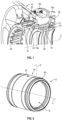
- FIG. 1 represents a first single-piece flexible cage technology 10 according to the prior art.
- the flexible cage 10 ensures the connection of an external ring 12 of a rolling bearing 14 to an annular support 16 of this bearing 14.
- the bearing 14 comprises, in addition to the outer ring 12, an inner ring 18 which is integral with a shaft of the turbomachine which is not shown.
- the rings 12, 18 define a roller raceway in the example shown.
- the external ring 12 is here integrated into an internal cylindrical wall 10a of the cage 10 which comprises a radially external annular flange 10b for fixing to the support 16 by screw-nut type means not shown.
- the cage 10 here comprises two series of columns 20, 22, respectively radially internal and external relative to the axis X of the bearing 14 and the shaft which it guides.
- the axis X corresponds to the engine axis of the turbomachine.
- the columns 20, 22 are distributed around the axis X and extend parallel to this axis.
- the columns 20 extend around the columns 22 and have a first of their longitudinal ends which is connected to the flange 10b, and a second of their longitudinal ends which is connected to the other columns 22 by an annular portion 24 with a C-section of the cage 10.
- the columns 22 extend from the wall 10a, in the extension thereof, to this portion 24.
- the support 16 is part of a stator of the turbomachine and here has a substantially truncated general shape. At its internal periphery, it comprises an internal cylindrical surface 16a for hooping a ring 26 which extends around the wall 10a of the cage and which defines with the latter an annular space 28 supplied with oil in order to form a film of oil for damping the vibrations transmitted by the bearing 14 in operation.
- the stiffness of the cage 10 and the bearing 14 is the same in all transverse directions (perpendicular to the X axis).
- the frequencies of the modes created will frame the frequency of the initial single mode.
- Control of the movements of the shaft according to the azimuth can also be used to improve the performance of the engine. Indeed, under mechanical or thermal loading the frame of the engine deforms, these distortions generate different openings and closings of clearances according to the azimuth. This implies a degradation of the performance of the engine which could be limited if the dynamic movement is optimized to compensate for part of the distortion, for example by stiffening the flexible cage in the direction of the clearance closing and by softening it in the direction of the clearance opening.
- the present invention makes it possible to meet this need thanks to elements connecting the ring 12 to the support 16, which are formed in a single piece with the ring and the support.
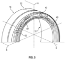
- FIGS 2 to 4 illustrate an embodiment of a device, according to the invention, for centering and guiding an aircraft turbomachine shaft.
- the device is symmetrical with respect to a median plane P perpendicular to an axis X, as shown in figure 2 .
- This means that the device has two identical axial ends. In other words, what is described below for a first axial end of the device also applies to the other axial end, opposite the first.
- the ring 12, the support 16 and the connecting elements 40 are formed in a single piece.
- the device is a single piece.
- the support 16 is here also formed in a single piece with the ring 12 and the elements 40.
- the outer ring 12 comprises a cylindrical portion 12b which has at its outer periphery an outer cylindrical surface 12d defining with the support 16 an annular space 50 for forming a damping oil film.
- the ring 12 also comprises at each of its ends an internal cylindrical rim 12c extending in the axial extension of the cylindrical portion 12b.
- An internal cylindrical rim 12c is understood to mean a rim which extends, in the axial extension of the ring 12, as close as possible to the axis X.
- the thickness of the rim 12c is less than the thickness of the cylindrical portion 12b of the ring 12.
- the support 16 comprises a cylindrical portion 16b which extends at least partly around the cylindrical portion 12b of the ring 12.
- the cylindrical portion 16b comprises at its internal periphery an internal cylindrical surface 16a defining with the external cylindrical surface 12d the aforementioned annular space 50 for forming a damping oil film.
- the support 16 comprises at least one oil supply orifice 52 and at least one oil discharge orifice, each of these orifices communicating with the annular space 50. These orifices are located on the external periphery of the cylindrical part 16b.
- the supply orifice 52 can open into a first annular groove, not visible here, which makes it possible to ensure an equal distribution of the oil in the annular space 50. In the case where several supply orifices 52 are present, several first annular grooves ensure the distribution of the oil
- the support 16 also comprises at each of its ends an external cylindrical rim 16c which extends in the axial extension of the cylindrical part 16b, and which extends around the internal rim 12c.
- An external cylindrical rim 16c is understood to mean a rim which extends, in the axial extension of the support 16, as far as possible from the axis X.
- the thickness of the rim 16c is less than the thickness of the cylindrical part of the support 16.
- the internal cylindrical rim 12c may be called the first cylindrical rim 12c and the external cylindrical rim 16c may be called the second cylindrical rim 16c.
- the connecting elements 40 are located at an axial end of the annular space 50. They are located on a circumference C1 having a diameter substantially equal to the diameter of the space 50. This means that the geometric center of each of the elements 40 is located on this circumference C1. It is understood that a portion of the shape of the element 40 may be outside this circumference C1, in other words a portion of the element 40 may be located on a circumference with a diameter substantially greater or less than the diameter of the circumference C1.
- the connecting elements 40 are elastically deformable and can be formed by blades, themselves elastically deformable.
- a blade is understood to mean a strip that is thin and long, the thickness of which is less than the width, width which extends in a direction substantially parallel to the axis X.
- the blades are interposed between the internal cylindrical rim 12c of the ring 12 and the external cylindrical rim 16c of the support 16.
- each of the blades is connected to the rim 16c of the support 16 by its first end 40a, radially external, and to the rim 12c of the ring 12 by its second end 40b, radially internal.
- the connecting elements 40 are enclosed in an annular housing 60.
- This housing 60 is delimited radially by the internal cylindrical rim 12c and the external cylindrical rim 16c, and is closed laterally by the cumulative excess thickness of the cylindrical parts 12b, 16b, between which the annular space 50 extends, and by an annular web 62.
- the term web 62 means a wall that is thin, in particular the thickness of the web 62 is less than the thickness of the rims 12c, 16c that it connects by being formed in one piece with the ring 12 and the support 16.
- the web 62 is elastically deformable and can take a corrugated shape in the radial direction.
- the web 62 can, for example, take a general bellows shape or have an ⁇ shape in section.
- Such a shape allows the web 62 to be able to absorb the relative movements between the ring 12 and the support 16 in an axial direction.
- the web 62 also has the advantage of ensuring lateral sealing of the annular space 50 for forming the damping oil film. Indeed, since the web 62 is in one piece with the ring 12 and the support 16, the oil cannot escape laterally from the device.
- the housing 60 can contain oil coming from the annular space 50.
- the connecting elements 40 can be immersed in oil.
- At least one oil evacuation hole may be present in the housing 60. This hole is calibrated so as to evacuate the oil from the housing 60 with a flow rate equivalent to the oil flow rate necessary for the formation of the damping oil film in the annular space 50. Furthermore, to ensure better evacuation, the holes may open into a second annular groove.
- annular segments axially delimit the annular space 50. It is understood that only the annular space 50 contains oil. Each segment comprises a leak calibrated so as to evacuate the oil from the annular space 50 with a flow rate substantially lower than the supply flow rate of the annular space 50. This leak is calibrated to have a flow rate substantially lower than the evacuation flow rate of the evacuation hole of the housing 60. The oil is evacuated via an outlet at a low point.
- the blades each have a general “S” shape. Such a shape has the advantage of having curvatures 41a, 41b at the ends 40a, 40b of the blade. Indeed, a first curvature 41a, at the first end 40a, is oriented in a first direction, and a second curvature 41b, at the second end 40b, is oriented in a second direction, opposite to the first.
- An "S" shape also has the advantage of having a center of symmetry.
- This center of symmetry corresponds to the geometric center of the shape and is substantially located on the circumference C1.
- a first junction between the first end 40a and the support 16 is symmetrical, with respect to this center of symmetry, to a second junction between the second end 40b and the ring 12.
- the first junction, the second junction and the center of symmetry, located in the same plane are radially aligned with the center of the device through which the axis X passes.
- Another advantage of the “S” shape is to give the elements 40 at least two different stiffnesses depending on the direction of a stress. Indeed, with a so-called vertical stress, that is to say in a direction tangent to the curvatures 41a, 41b, the elements 40 can deform. The curvatures 41a, 41b ensure the flexibility of the elements 40. With a so-called horizontal stress, perpendicular to the vertical stress, the elements 40 do not deform.
- This “S” shape is not limiting and the blades can adopt any shape offering different stiffness in two directions in a plane orthogonal to the axis of rotation of the motor shaft, in other words the X axis.
- the connecting elements 40 are arranged around the X axis. They can be distributed with a regular pitch, that is to say that between two consecutive elements 40, the distance is identical. They can also be distributed with an irregular pitch, that is to say that the distance between the elements 40 can vary. In a non-limiting example, there can be a first set of elements 40, spaced from each other by the same distance or the same pitch, and a second set of elements 40, spaced from each other by the same distance but spaced from the first set by a different distance. It is thus understood that the pitch between the elements 40 can be regular and/or irregular.
- the device can be produced by additive manufacturing. This can be metal additive manufacturing, for example by powder sintering. Since the device can comprise elements 40 with a particular conformation, such a technique allows, among other things, a simplified production of the device, by eliminating assembly and adjustment steps. In addition, this allows the configuration of the parts to be easily and quickly modified during the development phase.
- a set of elements 40 is distributed around the X axis. It is understood that the cage 10 is not axisymmetric with respect to the X axis and its stiffness is also not axisymmetric.
- Each of the elements 40 is arranged with a given inclination with respect to the radial direction. In other words, each element 40 has an inclination with respect to the radial direction which is specific to it. In this way, an overall stiffness is obtained when the device is stressed in a first direction (arrow F1), or in a second direction (arrow F2) orthogonal to the first direction.
- the first direction can for example be vertical and the second direction, orthogonal to the first, can for example be horizontal. Thanks to this given inclination, it is understood that each element 40 deforms differently according to the stresses F1 or F2, and has a stiffness which is specific to it. In this way, all the elements 40 work, which makes it possible to limit the concentration of stresses.
- the device is similar to what was previously described. It comprises a first set of elements 40 and a second set of elements 40'.
- the second set of elements 40' is symmetrical to the first set of elements 40 with respect to a plane A of symmetry.
- the device may also comprise, although not shown here, two other sets of elements 40, 40': a third set of elements 40' and a fourth set of elements 40.
- the third set of elements 40' may be positioned opposite the first set of elements 40 with respect to a plane B of symmetry. It is understood that this third set is identical to the second set.
- the fourth set of elements 40 may be positioned opposite the second set of elements 40' with respect to the plane B, the fourth set being symmetrical to the second set. It is understood that the fourth set is also symmetrical to the third set with respect to plane A and it is also understood that the fourth set is identical to the first set of elements 40.
- a given first step separates the elements 40, 40' for each set of elements 40, 40'. It is understood that this first step is identical for each of the sets.
- a second step different from the first step, separates each set. This second step can be less than or greater than the first step.
- the invention also relates to an aircraft turbomachine comprising at least one device as described above.
- the device and the flexible cage according to the invention are thus advantageous insofar as the stiffness of the cage is different depending on the angular position of the force transmitted to the cage in a direction transverse to its main axis. It is in fact particularly interesting for stabilizing a shaft to provide different stiffnesses in different transverse directions because this makes it possible to delay the speed of appearance of instabilities of the shaft guided by the device.
Landscapes
- Engineering & Computer Science (AREA)
- General Engineering & Computer Science (AREA)
- Mechanical Engineering (AREA)
- Chemical & Material Sciences (AREA)
- Combustion & Propulsion (AREA)
- Physics & Mathematics (AREA)
- Acoustics & Sound (AREA)
- Aviation & Aerospace Engineering (AREA)
- Rolling Contact Bearings (AREA)
- Support Of The Bearing (AREA)
- Structures Of Non-Positive Displacement Pumps (AREA)
Claims (9)
- Zentrier- und Führungsvorrichtung einer Flugzeug-Turbotriebwerkwelle, wobei diese Vorrichtung umfasst:- einen Außenring (12) eines Walzlagers, wobei sich dieser Ring um eine Achse (X) erstreckt,- eine ringförmige Lagerhalterung (16), die sich um die Achse (X) und mindestens teilweise um den Ring (12) erstreckt,- mindestens eine Reihe von Elementen (40) zur Verbindung des Rings mit der Halterung, wobei diese Elemente elastisch verformbar sind und um die Achse (X) mit einer Neigung in Bezug auf eine radiale Richtung verteilt sind, die jedem Element eigen ist,wobei der Ring, die Halterung und die Verbindungselemente einstückig gebildet sind,dadurch gekennzeichnet, dass die Verbindungselemente eingefügt sind zwischen einer zylindrischen Innenkante (12c) des Rings (12) und einer zylindrischen Außenkante (16c) der Halterung (16), die sich um die Innenkante erstreckt, und jeweils ein erstes, radial äußeres Ende (40a) zur Verbindung mit der zylindrischen Außenkante und ein zweites, radial inneres Ende (40b) zur Verbindung mit der zylindrischen Innenkante umfassen, und dadurch, dass die Verbindungselemente (40) in einem ringförmigen Sitz (60) umschlossen sind, der radial von den Kanten (12c, 16c) begrenzt wird, wobei der ringförmige Sitz seitlich durch eine ringförmige Bahn (62) verschlossen wird, die elastisch verformbar ist und die Kanten verbindet (12c, 16c), indem sie einstückig mit dem Ring (12) und der Halterung (16) gebildet ist.
- Vorrichtung nach dem vorstehenden Anspruch, wobei der Außenring (12) eine zylindrische Außenfläche (12d) umfasst, die mit einer zylindrischen Innenfläche (16a) der Halterung (16) einen ringförmigen Raum (50) zur Bildung eines Dämpfungsölfilms definiert.
- Vorrichtung nach dem vorstehenden Anspruch, wobei sich die Verbindungselemente (40) an einem axialen Ende des Raums (50) befinden und sich auf einem Umfang (C1) befinden, der einen Durchmesser im Wesentlichen gleich dem Durchmesser des Raums aufweist.
- Vorrichtung nach einem der vorstehenden Ansprüche, wobei die Verbindungselemente (40) durch Klingen gebildet sind.
- Vorrichtung nach dem vorstehenden Anspruch, wobei die Klingen jeweils eine allgemeine S-Form aufweisen.
- Vorrichtung nach einem der Ansprüche 4 oder 5, wobei sich eine erste Reihe von Klingen und eine erste Bahn (62) an einem axialen Ende der Vorrichtung befinden und eine zweite Reihe von Klingen und eine zweite Bahn (62) an einem gegenüberliegenden axialen Ende der Vorrichtung befinden.
- Vorrichtung nach dem vorstehenden Anspruch, in Abhängigkeit von Anspruch 2 oder 3, wobei die erste und die zweite Bahn (62) seitliche Abdichtungen des Raums (50) bilden, wobei die Halterung mindestens eine Zufuhröffnung (52) und mindestens eine Ablassöffnung für Öl aus diesem Raum umfasst.
- Vorrichtung nach einem der vorstehenden Ansprüche, wobei die Bahn (62) eine allgemeine Balgform aufweist.
- Flugzeug-Turbotriebwerk, das mindestens eine Vorrichtung nach einem der vorstehenden Ansprüche umfasst.
Applications Claiming Priority (2)
| Application Number | Priority Date | Filing Date | Title |
|---|---|---|---|
| FR2102712A FR3120904B1 (fr) | 2021-03-18 | 2021-03-18 | Dispositif de centrage et de guidage d’un arbre de turbomachine d’aeronef |
| PCT/FR2022/050410 WO2022195193A1 (fr) | 2021-03-18 | 2022-03-08 | Dispositif de centrage et de guidage d'un arbre de turbomachine d'aeronef |
Publications (2)
| Publication Number | Publication Date |
|---|---|
| EP4308798A1 EP4308798A1 (de) | 2024-01-24 |
| EP4308798B1 true EP4308798B1 (de) | 2024-11-20 |
Family
ID=75850338
Family Applications (1)
| Application Number | Title | Priority Date | Filing Date |
|---|---|---|---|
| EP22713701.5A Active EP4308798B1 (de) | 2021-03-18 | 2022-03-08 | Zentrier- und führungsvorrichtung für eine flugzeug-turbomaschinenwelle |
Country Status (5)
| Country | Link |
|---|---|
| US (1) | US12055097B2 (de) |
| EP (1) | EP4308798B1 (de) |
| CN (1) | CN117083448A (de) |
| FR (1) | FR3120904B1 (de) |
| WO (1) | WO2022195193A1 (de) |
Families Citing this family (2)
| Publication number | Priority date | Publication date | Assignee | Title |
|---|---|---|---|---|
| FR3120902B1 (fr) * | 2021-03-18 | 2023-03-10 | Safran Aircraft Engines | Dispositif de centrage et de guidage d’un arbre de turbomachine d’aeronef |
| WO2026019848A1 (en) * | 2024-07-16 | 2026-01-22 | Beehive Industries, LLC | Grooved bearing support |
Citations (3)
| Publication number | Priority date | Publication date | Assignee | Title |
|---|---|---|---|---|
| GB2415019A (en) * | 2004-06-07 | 2005-12-14 | Boc Group Plc | A supporting arrangement for a roller bearing |
| JP2011144924A (ja) * | 2009-12-18 | 2011-07-28 | Mitsubishi Heavy Ind Ltd | ダンパ軸受装置 |
| US20190353051A1 (en) * | 2018-05-15 | 2019-11-21 | General Electric Company | Variable Stiffness Static Structure |
Family Cites Families (19)
| Publication number | Priority date | Publication date | Assignee | Title |
|---|---|---|---|---|
| US3709570A (en) * | 1970-12-28 | 1973-01-09 | Trw Inc | Anti-friction bearing housing |
| US5054938A (en) * | 1987-05-29 | 1991-10-08 | Ide Russell D | Hydrodynamic bearings having beam mounted bearing pads and sealed bearing assemblies including the same |
| US5743654A (en) * | 1987-05-29 | 1998-04-28 | Kmc, Inc. | Hydrostatic and active control movable pad bearing |
| US5380100A (en) * | 1994-02-04 | 1995-01-10 | Yu; Han J. | Squeeze film damper covered by torus shells |
| SE517176C2 (sv) * | 1997-06-11 | 2002-04-23 | Alfa Laval Ab | Stödanordning för en centrifugalseparator |
| US8083413B2 (en) * | 2007-10-23 | 2011-12-27 | General Electric Company | Compliant hybrid gas journal bearing using integral wire mesh dampers |
| US8182153B2 (en) * | 2009-02-27 | 2012-05-22 | General Electric Company | Bearing damper with spring seal |
| DE102012221369A1 (de) | 2012-11-22 | 2014-05-22 | Schaeffler Technologies Gmbh & Co. Kg | Wälzlager |
| FR3009843B1 (fr) | 2013-08-26 | 2015-09-25 | Snecma | Colonnettes de support d'une bague exterieure de palier de roulement pour turbomachine d'aeronef, et procede de montage desdites colonnettes |
| US9850814B2 (en) * | 2014-02-19 | 2017-12-26 | United Technologies Corporation | Annular spring for a bearing assembly of a gas turbine engine |
| US9677659B1 (en) * | 2016-01-28 | 2017-06-13 | General Electric Company | Gearbox planet attenuation spring damper |
| DE102017100571A1 (de) | 2017-01-13 | 2018-03-01 | Schaeffler Technologies AG & Co. KG | Lagerkäfig für ein Lager |
| DE102017100572A1 (de) * | 2017-01-13 | 2018-03-01 | Schaeffler Technologies AG & Co. KG | Wälzlager |
| FR3078370B1 (fr) | 2018-02-28 | 2020-02-14 | Safran Helicopter Engines | Ensemble pour une turbomachine |
| US10450893B1 (en) * | 2019-02-01 | 2019-10-22 | United Technologies Corporation | Bearing centering spring and damper |
| FR3094031B1 (fr) * | 2019-03-18 | 2021-05-14 | Safran Aircraft Engines | Ensemble pour une turbomachine |
| US10753391B1 (en) * | 2019-04-05 | 2020-08-25 | Raytheon Technologies Corporation | Compact centering spring configuration, retention, and bladeout features |
| FR3096072B1 (fr) * | 2019-05-14 | 2021-04-30 | Safran Aircraft Engines | Turbomachine comprenant un amortisseur de palier d’arbre à viscance variable |
| US10794222B1 (en) * | 2019-08-14 | 2020-10-06 | General Electric Company | Spring flower ring support assembly for a bearing |
-
2021
- 2021-03-18 FR FR2102712A patent/FR3120904B1/fr active Active
-
2022
- 2022-03-08 EP EP22713701.5A patent/EP4308798B1/de active Active
- 2022-03-08 US US18/549,796 patent/US12055097B2/en active Active
- 2022-03-08 CN CN202280021256.3A patent/CN117083448A/zh active Pending
- 2022-03-08 WO PCT/FR2022/050410 patent/WO2022195193A1/fr not_active Ceased
Patent Citations (3)
| Publication number | Priority date | Publication date | Assignee | Title |
|---|---|---|---|---|
| GB2415019A (en) * | 2004-06-07 | 2005-12-14 | Boc Group Plc | A supporting arrangement for a roller bearing |
| JP2011144924A (ja) * | 2009-12-18 | 2011-07-28 | Mitsubishi Heavy Ind Ltd | ダンパ軸受装置 |
| US20190353051A1 (en) * | 2018-05-15 | 2019-11-21 | General Electric Company | Variable Stiffness Static Structure |
Also Published As
| Publication number | Publication date |
|---|---|
| FR3120904B1 (fr) | 2023-03-24 |
| WO2022195193A1 (fr) | 2022-09-22 |
| US20240151182A1 (en) | 2024-05-09 |
| CN117083448A (zh) | 2023-11-17 |
| EP4308798A1 (de) | 2024-01-24 |
| US12055097B2 (en) | 2024-08-06 |
| FR3120904A1 (fr) | 2022-09-23 |
Similar Documents
| Publication | Publication Date | Title |
|---|---|---|
| EP2801702B1 (de) | Stator-innenring eines turbotriebwerks mit abriebmaterial | |
| CA2776313C (fr) | Dispositif de centrage et de guidage en rotation d'un arbre de turbomachine | |
| EP4308798B1 (de) | Zentrier- und führungsvorrichtung für eine flugzeug-turbomaschinenwelle | |
| EP2718546B1 (de) | Turbinenmotor mit schwimmendem lager zum steuern einer welle des turbinenmotors | |
| EP4034776B1 (de) | Turbomaschinengebläseanordnung mit einem rollenlager und einem zweireihigen kugellager mit schrägkontakt | |
| CA2725864C (fr) | Turbine haute pression d'une turbomachine avec montage ameliore du boitier de pilotage des jeux radiaux d'aubes mobiles | |
| EP4308800A1 (de) | Vorrichtung zur zentrierung und führung einer welle eines flugzeugturbinentriebwerks | |
| EP3682139A1 (de) | Drehzapfen für ein gleitlager | |
| EP4308799B1 (de) | Zentrier- und führungsvorrichtung für eine flugzeug-turbomaschinenwelle | |
| CA2647152C (fr) | Dispositif de decouplage d'un support de palier | |
| EP3580431B1 (de) | Ring zur verminderung des überdrucks in der nähe der stromaufwärtigen dichtung eines lagergehäuses eines turbinen-strahltriebwerks | |
| FR3014155A1 (fr) | Cage de roulement avec un jonc peripherique d'amortissement de vibrations | |
| FR3087481A1 (fr) | Ensemble d’equilibrage modulaire pour turbomachine | |
| EP2333365B1 (de) | Abstandshalter angepasster Länge für Wälzlager | |
| FR3120899A1 (fr) | Dispositif de centrage et de guidage d’un arbre de turbomachine d’aeronef | |
| EP3532732B1 (de) | Laufrad für kreiselpumpe, kreiselpumpe und herstellungsverfahren | |
| EP3682138A1 (de) | Drehzapfen für ein gleitlager | |
| FR3137121A1 (fr) | Ensemble aubagé à liaison inter-plateformes par élément roulant interposé | |
| WO2023194677A1 (fr) | Turbomachine d'aeronef comprenant un support de roulement a conception amelioree | |
| EP4204701A1 (de) | Radlager, das mit einer dichtungsvorrichtung mit rinne und schikane ausgestattet ist | |
| FR3126961A1 (fr) | Helice pour une turbomachine d’aeronef | |
| FR3079553A1 (fr) | Ensemble pour turbomachine | |
| FR3042215B1 (fr) | Structure pour turbomachine comportant des moyens de retention axiale de bague exterieure de palier de roulement | |
| EP4374048A1 (de) | Auf einer niederdruckwelle in einer turbomaschine montierte hülse | |
| FR2779769A1 (fr) | Groupe turbopompe |
Legal Events
| Date | Code | Title | Description |
|---|---|---|---|
| STAA | Information on the status of an ep patent application or granted ep patent |
Free format text: STATUS: UNKNOWN |
|
| STAA | Information on the status of an ep patent application or granted ep patent |
Free format text: STATUS: THE INTERNATIONAL PUBLICATION HAS BEEN MADE |
|
| PUAI | Public reference made under article 153(3) epc to a published international application that has entered the european phase |
Free format text: ORIGINAL CODE: 0009012 |
|
| STAA | Information on the status of an ep patent application or granted ep patent |
Free format text: STATUS: REQUEST FOR EXAMINATION WAS MADE |
|
| 17P | Request for examination filed |
Effective date: 20230928 |
|
| AK | Designated contracting states |
Kind code of ref document: A1 Designated state(s): AL AT BE BG CH CY CZ DE DK EE ES FI FR GB GR HR HU IE IS IT LI LT LU LV MC MK MT NL NO PL PT RO RS SE SI SK SM TR |
|
| DAV | Request for validation of the european patent (deleted) | ||
| DAX | Request for extension of the european patent (deleted) | ||
| GRAP | Despatch of communication of intention to grant a patent |
Free format text: ORIGINAL CODE: EPIDOSNIGR1 |
|
| STAA | Information on the status of an ep patent application or granted ep patent |
Free format text: STATUS: GRANT OF PATENT IS INTENDED |
|
| INTG | Intention to grant announced |
Effective date: 20240816 |
|
| GRAS | Grant fee paid |
Free format text: ORIGINAL CODE: EPIDOSNIGR3 |
|
| GRAA | (expected) grant |
Free format text: ORIGINAL CODE: 0009210 |
|
| STAA | Information on the status of an ep patent application or granted ep patent |
Free format text: STATUS: THE PATENT HAS BEEN GRANTED |
|
| AK | Designated contracting states |
Kind code of ref document: B1 Designated state(s): AL AT BE BG CH CY CZ DE DK EE ES FI FR GB GR HR HU IE IS IT LI LT LU LV MC MK MT NL NO PL PT RO RS SE SI SK SM TR |
|
| REG | Reference to a national code |
Ref country code: GB Ref legal event code: FG4D Free format text: NOT ENGLISH |
|
| REG | Reference to a national code |
Ref country code: CH Ref legal event code: EP |
|
| REG | Reference to a national code |
Ref country code: DE Ref legal event code: R096 Ref document number: 602022007965 Country of ref document: DE |
|
| REG | Reference to a national code |
Ref country code: IE Ref legal event code: FG4D Free format text: LANGUAGE OF EP DOCUMENT: FRENCH |
|
| REG | Reference to a national code |
Ref country code: LT Ref legal event code: MG9D |
|
| REG | Reference to a national code |
Ref country code: NL Ref legal event code: MP Effective date: 20241120 |
|
| PG25 | Lapsed in a contracting state [announced via postgrant information from national office to epo] |
Ref country code: HR Free format text: LAPSE BECAUSE OF FAILURE TO SUBMIT A TRANSLATION OF THE DESCRIPTION OR TO PAY THE FEE WITHIN THE PRESCRIBED TIME-LIMIT Effective date: 20241120 Ref country code: IS Free format text: LAPSE BECAUSE OF FAILURE TO SUBMIT A TRANSLATION OF THE DESCRIPTION OR TO PAY THE FEE WITHIN THE PRESCRIBED TIME-LIMIT Effective date: 20250320 Ref country code: PT Free format text: LAPSE BECAUSE OF FAILURE TO SUBMIT A TRANSLATION OF THE DESCRIPTION OR TO PAY THE FEE WITHIN THE PRESCRIBED TIME-LIMIT Effective date: 20250320 |
|
| PGFP | Annual fee paid to national office [announced via postgrant information from national office to epo] |
Ref country code: DE Payment date: 20250218 Year of fee payment: 4 |
|
| PG25 | Lapsed in a contracting state [announced via postgrant information from national office to epo] |
Ref country code: FI Free format text: LAPSE BECAUSE OF FAILURE TO SUBMIT A TRANSLATION OF THE DESCRIPTION OR TO PAY THE FEE WITHIN THE PRESCRIBED TIME-LIMIT Effective date: 20241120 Ref country code: NL Free format text: LAPSE BECAUSE OF FAILURE TO SUBMIT A TRANSLATION OF THE DESCRIPTION OR TO PAY THE FEE WITHIN THE PRESCRIBED TIME-LIMIT Effective date: 20241120 |
|
| REG | Reference to a national code |
Ref country code: AT Ref legal event code: MK05 Ref document number: 1743751 Country of ref document: AT Kind code of ref document: T Effective date: 20241120 |
|
| PG25 | Lapsed in a contracting state [announced via postgrant information from national office to epo] |
Ref country code: BG Free format text: LAPSE BECAUSE OF FAILURE TO SUBMIT A TRANSLATION OF THE DESCRIPTION OR TO PAY THE FEE WITHIN THE PRESCRIBED TIME-LIMIT Effective date: 20241120 |
|
| PG25 | Lapsed in a contracting state [announced via postgrant information from national office to epo] |
Ref country code: ES Free format text: LAPSE BECAUSE OF FAILURE TO SUBMIT A TRANSLATION OF THE DESCRIPTION OR TO PAY THE FEE WITHIN THE PRESCRIBED TIME-LIMIT Effective date: 20241120 |
|
| PG25 | Lapsed in a contracting state [announced via postgrant information from national office to epo] |
Ref country code: NO Free format text: LAPSE BECAUSE OF FAILURE TO SUBMIT A TRANSLATION OF THE DESCRIPTION OR TO PAY THE FEE WITHIN THE PRESCRIBED TIME-LIMIT Effective date: 20250220 |
|
| PG25 | Lapsed in a contracting state [announced via postgrant information from national office to epo] |
Ref country code: GR Free format text: LAPSE BECAUSE OF FAILURE TO SUBMIT A TRANSLATION OF THE DESCRIPTION OR TO PAY THE FEE WITHIN THE PRESCRIBED TIME-LIMIT Effective date: 20250221 Ref country code: AT Free format text: LAPSE BECAUSE OF FAILURE TO SUBMIT A TRANSLATION OF THE DESCRIPTION OR TO PAY THE FEE WITHIN THE PRESCRIBED TIME-LIMIT Effective date: 20241120 Ref country code: LV Free format text: LAPSE BECAUSE OF FAILURE TO SUBMIT A TRANSLATION OF THE DESCRIPTION OR TO PAY THE FEE WITHIN THE PRESCRIBED TIME-LIMIT Effective date: 20241120 |
|
| PG25 | Lapsed in a contracting state [announced via postgrant information from national office to epo] |
Ref country code: PL Free format text: LAPSE BECAUSE OF FAILURE TO SUBMIT A TRANSLATION OF THE DESCRIPTION OR TO PAY THE FEE WITHIN THE PRESCRIBED TIME-LIMIT Effective date: 20241120 |
|
| PGFP | Annual fee paid to national office [announced via postgrant information from national office to epo] |
Ref country code: FR Payment date: 20250218 Year of fee payment: 4 |
|
| PG25 | Lapsed in a contracting state [announced via postgrant information from national office to epo] |
Ref country code: RS Free format text: LAPSE BECAUSE OF FAILURE TO SUBMIT A TRANSLATION OF THE DESCRIPTION OR TO PAY THE FEE WITHIN THE PRESCRIBED TIME-LIMIT Effective date: 20250220 |
|
| PG25 | Lapsed in a contracting state [announced via postgrant information from national office to epo] |
Ref country code: SM Free format text: LAPSE BECAUSE OF FAILURE TO SUBMIT A TRANSLATION OF THE DESCRIPTION OR TO PAY THE FEE WITHIN THE PRESCRIBED TIME-LIMIT Effective date: 20241120 |
|
| PG25 | Lapsed in a contracting state [announced via postgrant information from national office to epo] |
Ref country code: DK Free format text: LAPSE BECAUSE OF FAILURE TO SUBMIT A TRANSLATION OF THE DESCRIPTION OR TO PAY THE FEE WITHIN THE PRESCRIBED TIME-LIMIT Effective date: 20241120 |
|
| PG25 | Lapsed in a contracting state [announced via postgrant information from national office to epo] |
Ref country code: EE Free format text: LAPSE BECAUSE OF FAILURE TO SUBMIT A TRANSLATION OF THE DESCRIPTION OR TO PAY THE FEE WITHIN THE PRESCRIBED TIME-LIMIT Effective date: 20241120 |
|
| PG25 | Lapsed in a contracting state [announced via postgrant information from national office to epo] |
Ref country code: RO Free format text: LAPSE BECAUSE OF FAILURE TO SUBMIT A TRANSLATION OF THE DESCRIPTION OR TO PAY THE FEE WITHIN THE PRESCRIBED TIME-LIMIT Effective date: 20241120 |
|
| PG25 | Lapsed in a contracting state [announced via postgrant information from national office to epo] |
Ref country code: SK Free format text: LAPSE BECAUSE OF FAILURE TO SUBMIT A TRANSLATION OF THE DESCRIPTION OR TO PAY THE FEE WITHIN THE PRESCRIBED TIME-LIMIT Effective date: 20241120 |
|
| PG25 | Lapsed in a contracting state [announced via postgrant information from national office to epo] |
Ref country code: CZ Free format text: LAPSE BECAUSE OF FAILURE TO SUBMIT A TRANSLATION OF THE DESCRIPTION OR TO PAY THE FEE WITHIN THE PRESCRIBED TIME-LIMIT Effective date: 20241120 |
|
| PG25 | Lapsed in a contracting state [announced via postgrant information from national office to epo] |
Ref country code: IT Free format text: LAPSE BECAUSE OF FAILURE TO SUBMIT A TRANSLATION OF THE DESCRIPTION OR TO PAY THE FEE WITHIN THE PRESCRIBED TIME-LIMIT Effective date: 20241120 |
|
| REG | Reference to a national code |
Ref country code: DE Ref legal event code: R097 Ref document number: 602022007965 Country of ref document: DE |
|
| PG25 | Lapsed in a contracting state [announced via postgrant information from national office to epo] |
Ref country code: SE Free format text: LAPSE BECAUSE OF FAILURE TO SUBMIT A TRANSLATION OF THE DESCRIPTION OR TO PAY THE FEE WITHIN THE PRESCRIBED TIME-LIMIT Effective date: 20241120 |
|
| PLBE | No opposition filed within time limit |
Free format text: ORIGINAL CODE: 0009261 |
|
| STAA | Information on the status of an ep patent application or granted ep patent |
Free format text: STATUS: NO OPPOSITION FILED WITHIN TIME LIMIT |
|
| PG25 | Lapsed in a contracting state [announced via postgrant information from national office to epo] |
Ref country code: MC Free format text: LAPSE BECAUSE OF FAILURE TO SUBMIT A TRANSLATION OF THE DESCRIPTION OR TO PAY THE FEE WITHIN THE PRESCRIBED TIME-LIMIT Effective date: 20241120 |
|
| 26N | No opposition filed |
Effective date: 20250821 |
|
| REG | Reference to a national code |
Ref country code: CH Ref legal event code: H13 Free format text: ST27 STATUS EVENT CODE: U-0-0-H10-H13 (AS PROVIDED BY THE NATIONAL OFFICE) Effective date: 20251023 |
|
| PG25 | Lapsed in a contracting state [announced via postgrant information from national office to epo] |
Ref country code: LU Free format text: LAPSE BECAUSE OF NON-PAYMENT OF DUE FEES Effective date: 20250308 |
|
| REG | Reference to a national code |
Ref country code: BE Ref legal event code: MM Effective date: 20250331 |
|
| PG25 | Lapsed in a contracting state [announced via postgrant information from national office to epo] |
Ref country code: BE Free format text: LAPSE BECAUSE OF NON-PAYMENT OF DUE FEES Effective date: 20250331 |
|
| PG25 | Lapsed in a contracting state [announced via postgrant information from national office to epo] |
Ref country code: CH Free format text: LAPSE BECAUSE OF NON-PAYMENT OF DUE FEES Effective date: 20250331 |
|
| PG25 | Lapsed in a contracting state [announced via postgrant information from national office to epo] |
Ref country code: IE Free format text: LAPSE BECAUSE OF NON-PAYMENT OF DUE FEES Effective date: 20250308 |