EP2333365B1 - Abstandshalter angepasster Länge für Wälzlager - Google Patents
Abstandshalter angepasster Länge für Wälzlager Download PDFInfo
- Publication number
- EP2333365B1 EP2333365B1 EP10193049.3A EP10193049A EP2333365B1 EP 2333365 B1 EP2333365 B1 EP 2333365B1 EP 10193049 A EP10193049 A EP 10193049A EP 2333365 B1 EP2333365 B1 EP 2333365B1
- Authority
- EP
- European Patent Office
- Prior art keywords
- spacers
- bearings
- preload
- rings
- hub
- Prior art date
- Legal status (The legal status is an assumption and is not a legal conclusion. Google has not performed a legal analysis and makes no representation as to the accuracy of the status listed.)
- Active
Links
- 125000006850 spacer group Chemical group 0.000 title claims description 106
- 230000036316 preload Effects 0.000 claims description 64
- 238000005096 rolling process Methods 0.000 claims description 54
- 239000000463 material Substances 0.000 claims description 25
- 230000000694 effects Effects 0.000 claims description 20
- 238000000034 method Methods 0.000 claims description 4
- 238000003754 machining Methods 0.000 claims description 3
- 238000004519 manufacturing process Methods 0.000 claims description 3
- 230000000284 resting effect Effects 0.000 claims 6
- 230000003247 decreasing effect Effects 0.000 claims 2
- 239000010935 stainless steel Substances 0.000 description 7
- 229910001220 stainless steel Inorganic materials 0.000 description 7
- 230000007246 mechanism Effects 0.000 description 5
- 229910000831 Steel Inorganic materials 0.000 description 4
- 239000000919 ceramic Substances 0.000 description 4
- 238000006073 displacement reaction Methods 0.000 description 4
- 239000010959 steel Substances 0.000 description 4
- 230000005489 elastic deformation Effects 0.000 description 2
- 238000010438 heat treatment Methods 0.000 description 2
- 229910052751 metal Inorganic materials 0.000 description 2
- 239000002184 metal Substances 0.000 description 2
- 238000003825 pressing Methods 0.000 description 2
- 230000035945 sensitivity Effects 0.000 description 2
- 230000035939 shock Effects 0.000 description 2
- 229910000676 Si alloy Inorganic materials 0.000 description 1
- 229910001069 Ti alloy Inorganic materials 0.000 description 1
- 230000006978 adaptation Effects 0.000 description 1
- 230000002411 adverse Effects 0.000 description 1
- CSDREXVUYHZDNP-UHFFFAOYSA-N alumanylidynesilicon Chemical compound [Al].[Si] CSDREXVUYHZDNP-UHFFFAOYSA-N 0.000 description 1
- 230000009286 beneficial effect Effects 0.000 description 1
- 230000002349 favourable effect Effects 0.000 description 1
- 238000005461 lubrication Methods 0.000 description 1
- 238000012986 modification Methods 0.000 description 1
- 230000004048 modification Effects 0.000 description 1
- 238000007747 plating Methods 0.000 description 1
Images

Classifications
-
- F—MECHANICAL ENGINEERING; LIGHTING; HEATING; WEAPONS; BLASTING
- F16—ENGINEERING ELEMENTS AND UNITS; GENERAL MEASURES FOR PRODUCING AND MAINTAINING EFFECTIVE FUNCTIONING OF MACHINES OR INSTALLATIONS; THERMAL INSULATION IN GENERAL
- F16C—SHAFTS; FLEXIBLE SHAFTS; ELEMENTS OR CRANKSHAFT MECHANISMS; ROTARY BODIES OTHER THAN GEARING ELEMENTS; BEARINGS
- F16C25/00—Bearings for exclusively rotary movement adjustable for wear or play
- F16C25/06—Ball or roller bearings
- F16C25/08—Ball or roller bearings self-adjusting
-
- F—MECHANICAL ENGINEERING; LIGHTING; HEATING; WEAPONS; BLASTING
- F16—ENGINEERING ELEMENTS AND UNITS; GENERAL MEASURES FOR PRODUCING AND MAINTAINING EFFECTIVE FUNCTIONING OF MACHINES OR INSTALLATIONS; THERMAL INSULATION IN GENERAL
- F16C—SHAFTS; FLEXIBLE SHAFTS; ELEMENTS OR CRANKSHAFT MECHANISMS; ROTARY BODIES OTHER THAN GEARING ELEMENTS; BEARINGS
- F16C19/00—Bearings with rolling contact, for exclusively rotary movement
- F16C19/52—Bearings with rolling contact, for exclusively rotary movement with devices affected by abnormal or undesired conditions
- F16C19/525—Bearings with rolling contact, for exclusively rotary movement with devices affected by abnormal or undesired conditions related to temperature and heat, e.g. insulation
-
- Y—GENERAL TAGGING OF NEW TECHNOLOGICAL DEVELOPMENTS; GENERAL TAGGING OF CROSS-SECTIONAL TECHNOLOGIES SPANNING OVER SEVERAL SECTIONS OF THE IPC; TECHNICAL SUBJECTS COVERED BY FORMER USPC CROSS-REFERENCE ART COLLECTIONS [XRACs] AND DIGESTS
- Y10—TECHNICAL SUBJECTS COVERED BY FORMER USPC
- Y10T—TECHNICAL SUBJECTS COVERED BY FORMER US CLASSIFICATION
- Y10T29/00—Metal working
- Y10T29/49—Method of mechanical manufacture
- Y10T29/49636—Process for making bearing or component thereof
- Y10T29/49643—Rotary bearing
Definitions
- the invention relates to the field of rolling bearings. It relates more particularly to the bearings subjected to temperature gradients.
- Ball bearings have been used for decades in a considerable amount of equipment with rotating mechanisms. Their role is to limit the friction between two parts, one of which, the rotor, is rotatable relative to the other, the stator, fixed to the support, replacing the phenomenon of sliding between the two parts by a phenomenon of rolling.
- a ball or tapered roller bearing is then usually composed of two coaxial rings comprising rolling tracks, between which is disposed a series of rolling elements (balls or rollers) whose spacing is kept constant. It will be limited in the rest of the discussion to the case of ball bearings, although the invention is not limited to this case.
- the rings of the bearings and the balls are conventionally metallic, most often made of rolling steel. For some applications, steel rings and ceramic balls are also used. Fully ceramic bearings also exist.
- shaft means the part of the part in contact with the inner rings of the bearings, this part being either the stator when the central element of the bearing is fixed relative to the support, or the rotor when the central element of the bearing is in rotation relative to the support.
- hub means the part of the part in contact with the outer rings of the bearings, this part being the opposite of the shaft, either the rotor or the stator. In all cases, the hub envelops the shaft.
- Such rolling bearings are typically used in mechanisms, such as driving device, machine tool spindles, turbines, pointing mechanisms, precision mechanisms, kinetic wheel, such a kinetic wheel being used, for example, in a machine application. satellite attitude control.
- ball bearings are used preloaded to eliminate these games, and ensure good pointing accuracy.
- the preloading of a pair of bearings consists in permanently applying an axial clamping force on the faces of the bearings. This force causes an elastic deformation between tracks and balls and generates a contact pressure, which eliminates the game.
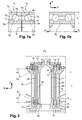
- FIG. 1a which illustrates a rolling bearing not yet preloaded, two ball bearings 1g, 1d are juxtaposed. Only half of the bearings are shown, the axis of symmetry Z of the bearings being horizontal in the figure.
- the inner rings 2g, 2d, and outer 3g, 3d are shown in section.
- the internal tracks 4g, 4d and the external tracks 5g, 5d define normals 6g, 6d in contact with the balls inclined at a predetermined contact angle ⁇ . Normals 6g and 6d being concurrent to the outside of the bearings, we speak of a back-to-back assembly.
- the reversal of the bearings 1g and 1d would lead to a so-called "face-to-face" mounting configuration where the normals in contact would be concurrent towards the inside of the bearings.
- the balls 7g, 7d are simply in contact with their respective inner and outer tracks. It remains intentionally a game 8 between the two inner rings 2g, 2d, while the two outer rings 3g, 3d are in contact.
- a preload is applied in the form of an axial force Pr plating the inner rings 2g, 2d against each other.
- This preload here causes an elastic deformation 9g, 9d (here very exaggerated for the purposes of the figure) of each ball 7g, 7d and tracks, preventing the appearance of play in the assembly.
- the oblique contact angle ⁇ increases slightly (typically by a few percent). The resulting contact angle is known and achieved within a few degrees by the bearing manufacturers, in a range typically ranging from 10 to 40 degrees.
- this preload is called rigid preload when the preload is applied by an imposed displacement of one of the rings relative to the other. We will limit ourselves here to the case of rigid preloads.
- Preloading is thus an important feature of the rolling bearing. It allows to give it a rigidity defined and controlled. It also has a direct influence on the allowable rotor loading and speed level. The difficulty for the designer is to guarantee a precharge controlled and stable over time.
- a known embodiment of the state of the art which provides both a rigid preload and a good rigidity of the tilt bearing, that is to say around axes perpendicular to the axis of the bearing, is as follows .
- a rolling bearing of the type comprising a central shaft and a hub movable in rotation relative to one another, comprises at least two bearings, one said lower, the other said upper, arranged between the shaft central and the hub according to two positions spaced in the axial direction (that is to say by definition along the Z axis).
- These bearings are provided with inner and outer rings and balls, the inner ring of each bearing being fitted around the central shaft and the outer ring being fitted inside the hub, the bearings being mounted back to back or face-to-face. to-face. Rigid preload is applied to these bearings in the axial direction.
- Spacers are arranged between the bearings, a so-called internal spacer being supported, by its upper and lower ends, on the inner rings of the upper and lower bearings respectively, a so-called outer spacer supported by its upper and lower ends on the rings. outer bearings of the upper and lower bearings respectively.
- Rigid preload is applied to the bearings in the axial direction by means of suitable mounting elements.
- suitable mounting elements For example we uses mounting flanges tightening the bearing rings on the spacers.
- This type of assembly is advantageous because it allows to move the bearings by an adjustable distance depending on the length of the spacers.
- the length of the spacers is chosen sufficiently large to ensure good pointing accuracy and the desired rigidity in tilting. The longer the spacers, the greater the rigidity of the tilt bearing.
- the spacers will have the minimum length to ensure the desired rigidity.
- This advantageous device in terms of tilt rigidity, bulk and mass, however, has a significant limitation for certain applications requiring that the preload remains substantially constant during temperature variations.
- the preload when subjecting a ball bearing to a temperature variation, the preload is substantially altered. It can increase, which degrades the friction torque and the wear life of the parts in contact. It can also decrease until complete loss of the preload, in which case, the resulting mechanical play degrades the pointing accuracy and also the service life due to shocks generated in the bearing.
- a temperature excursion is frequently encountered during the operation of the system, for example because of the heating of the bearings, particularly for high speeds of rotation, or because of the presence dissipative elements operating nearby, such as electronics for example.
- a temperature gradient is commonly encountered because the stator is in conductive thermal contact with the support, while the thermal conduction of the rotor towards the support passes through the bearing balls which offer a reduced thermal path, especially when they are made of a material with a low thermal conductivity, in particular if they are ceramic.
- JP 5 079514 discloses a "face-to-face" mounting of bearings where it is necessary to use materials having different thermal expansion coefficients for the inner and outer struts.
- the present invention therefore aims to remedy this problem by proposing a new bearing arrangement with preloaded bearings, adapted to take into account the temperature gradients.
- the invention is aimed primarily at a rolling bearing, of the type comprising a central shaft and a hub movable in rotation relative to one another, the bearing comprising at least two bearings, one said lower, the other said upper, arranged between the central shaft and the hub in two positions spaced in the axial direction Z, these bearings being provided with inner and outer rings and balls, the inner ring of each bearing being fitted around the central shaft and the outer ring inside the hub, the bearings being mounted back to back, a rigid preload being applied to these bearings in the axial direction, spacers being arranged between these bearings, a said spacer internal bearing supported by its upper and lower ends on the inner rings of the upper and lower bearings respectively, said outer spacer supported by its upper and lower ends on the outer rings of the upper and lower bearings respectively.
- the rolling bearing is such that the spacers, internal and external, have lengths adjusted to limit to less than 30% the variations of the rigid preload due to thermal gradients from one point to another of the bearing, in particular the thermal gradients in the radial direction, it being understood that, for an optimum length of the spacers, the effect of the axial differential expansion of the spacers (22, 23) on the preload, in the sense of an increase in the preload, compensates the effect of the radial differential expansion of the rings (14, 16, 15, 17), going in the direction of a decrease in this same preload.
- the lengths of the spacers will advantageously be adjusted to their optimum value with a tolerance of less than ten percent.
- the contact angle ( ⁇ ) of the balls is chosen to be greater than or equal to 25 degrees, so as to limit the bulk and the mass of the bearing while ensuring good rigidity.
- At least one of the rings, and preferably each of the rings of at least one bearing, is free to move in the axial direction relative to the other rings, for example thanks to a sliding fit with respect to its support. (shaft or hub).
- the shaft, hub, and rings are made of the same materials, or materials having substantially the same coefficient of thermal expansion.
- mounting flanges are used to tighten the bearing rings on the spacers and these flanges have a significantly lower stiffness (typically at least three times smaller) than the axial stiffness of the spacers.
- the rings and the balls will be manufactured in the same materials, or in materials having substantially the same coefficient of thermal expansion.
- the preload remains insensitive to a temperature excursion while the rings and balls are not made of the same materials, or in materials having substantially the same coefficient of thermal expansion, it will be advantageous to maintain the temperature of the bearing at neighborhood of a given average temperature, at temperature gradients.
- the lengths of the two spacers are identical, with the machining errors close.
- the bearings are of identical dimensions, and the bearing comprises for each group of two bearings spaced along the axial direction Z, two cylindrical and coaxial spacers.
- the bearing comprises at least between the central shaft and the inner spacer, or between the two spacers, or between the outer spacer and the hub, games adapted to allow radial differential expansion of the at least one of the spacers vis-à-vis the other spacer, or the central shaft, or the hub.
- one of the bearings is simply held in place by the spacers, on the one hand, and the clamps, on the other hand, these mounting flanges having a significantly lower stiffness (typically at less than three times lower) than the axial stiffness of the spacers.
- one of the bearings, said upper is simply held in place on one side by the spacers and on the other side by clamps
- the other bearing, said lower is simply held in place on one side by the spacers, and on the other side by shoulders arranged in the central shaft and the hub
- the assembly comprising the lower bearing, the spacers and the upper bearing thus forming a substantially cylindrical volume , of thickness equal to the thickness e of a bearing, and fitting into a housing of corresponding shape within the space between the central shaft and the hub.
- the invention also relates to a method of manufacturing a rolling bearing, of the type comprising a central shaft and a hub movable in rotation relative to each other, the bearing comprising at least two bearings, arranged between the central shaft and the hub in two positions spaced in the axial direction Z, these bearings being provided with rings, inside and outside, and balls, the inner ring of each bearing bearing on the central shaft and the outer ring on the hub, the bearings being mounted back to back, a rigid preload being applied to these bearings in the axial direction, spacers being arranged between these bearings, a so-called internal spacer bearing, by its upper and lower ends, on the inner rings of the upper and lower bearings respectively, an outer said spacer being supported, by its upper and lower ends, on the outer rings of the upper and lower bearings respectively.
- the method comprises a step of calculating the lengths of the spacers, internal and external, in order to minimize the variations in the rigid preload of the bearings due to predetermined thermal gradients from one point to the other of the bearing, in particular thermal gradients in the radial direction, this minimization using a compensation of the precharge variations, it being understood that, for an optimum length of the spacers, the effect of the axial differential expansion of the spacers on the preload, going in the direction of an increase in the preload , compensates the effect of radial differential expansion of the rings going in the direction of a decrease of this same preload.
- the invention relates to a rolling bearing for a device comprising a hub 10 rotatable about a central shaft 11.
- the figure 2 represents only the central part of the hub 10.
- the central shaft 11 and the hub 10 are designed in a conventional manner, and in non-detailed materials here, metal or other.
- the shaft and the hub are made of the same material, for example stainless steel (10.4 ⁇ m / m / C) or in different materials but having substantially the same coefficient of thermal expansion, which greatly facilitates the activities of design.
- Z is the axis of rotation of the hub 10 around the central shaft 11, and the terms "radial” and “axial” are defined by reference to this axis of rotation Z.
- the rolling bearing here comprises two bearings: lower 12, and upper 13, respectively, of identical dimensions.
- bearings are here of ball type, but it is clear that other types of bearings, for example conical rollers are possible without changing the principle of the invention.
- the bearings 12, 13 are assumed to have inner rings 14, 16 and outer 15, 17 metal, for example stainless steel, and balls 18, 19 also stainless steel.
- the lubrication process of bearings is not detailed here.
- the internal rings are fitted around the shaft (respectively inside the hub) with a sliding contact having a sufficiently small clearance (typically a few microns) to prevent damage to the bearing during lateral movements (in the radial direction) for example under the effect of vibrations or external shocks, but large enough so that at least one of the rings, and preferably each of the rings of at least one of the bearings is free to move in the axial direction by compared to other rings.
- the material of the bearing rings has substantially the same coefficient of thermal expansion as the material used for the shaft and the hub, so that the sets of adjustment between the inner rings and the shaft on the one hand, and between the outer rings and the hub on the other hand, are substantially constant during temperature excursion.
- each bearing 12, 13 is fixed, and that the outer ring 15, 17 is rotatable, integrally with the hub 10.
- the precise geometric characteristics of the bearings 12, 13 are outside the scope of FIG. the present invention, and are therefore not discussed further here.
- the bearings 12, 13 are mounted in a similar manner to the arrangement of the figure 1 , that is, back to back.
- the normals at the contact A1, A2 of the balls of the bearings 12, 13 are indeed concurrent towards the outside of the hub 10.
- a rigid precharge, of the type explained above, is applied to these bearings 12, 13 via flanges.
- the detail of these parts and their mode of operation is known to those skilled in the art and is therefore not detailed further here.
- two coaxial cylindrical pieces 22, 23, named "spacers" are interposed between these bearings.
- the inner spacer 22, bearing on the inner rings 14, 16, is fixed.
- the outer spacer 23, bearing on the outer rings 15, 17, is movable in rotation integrally with these rings.
- each spacer 22 and external 23 each bear on a ring of each bearing.
- the inner spacer 22 is supported, by its upper and lower ends, on the inner rings 16, 14 of the upper bearings 13 and lower 12 respectively.
- the outer spacer 23 is supported, by its upper and lower ends, on the outer rings 17, 15 of the upper bearings 13 and lower 12 respectively.
- Mounting flanges 20, 21 are used to tighten the bearing rings on the spacers 22, 23. They have a lower stiffness than the axial stiffness of the spacers, typically at least three times smaller than the axial stiffness of the spacers. In this way, the expansion of the spacers, which we will see that it plays a key role in maintaining the preload, will be little affected by the stiffness of the flanges.
- the spacers advantageously have the same length, errors machining close.
- the preload that would be obtained by pressing the bearings against each other as on the figure 1 is obtained in the same way by pressing the bearings against the spacers, thanks to the clamping flanges, whatever the relative arrangement of the shoulders on which the rings of the lower bearing before tightening rest.
- the hub and shaft will automatically adjust in the radial direction.
- the lengths of the two spacers are different, but adjusted so that the desired preload is achieved when mounting the bearing.
- the central shaft 11 has a substantially cylindrical recess 24 arranged in line with the internal spacer 22.
- the hub 10 comprises a recess 25 of mainly cylindrical shape to the right of the outer spacer 23.
- the spacers 22, 23 are separated by a space also of substantially cylindrical shape 26.
- the upper bearing 13 is simply held in place in the axial direction by the spacers 22, 23, on the one hand, and the clamps 20, 21, on the other hand.
- the lower bearing 12 is simply held in place by the spacers 22, 23 on the one hand, and shoulders 27, 28 formed in the central shaft 11 and the hub 10.
- the assembly comprising the lower bearing 12, the spacers 22, 23 and the upper bearing 13 thus form a substantially cylindrical volume, of thickness equal to the thickness e of a bearing (see figure 1 ), and fits into a correspondingly shaped housing within the space between the central shaft 11 and the hub 10.
- This arrangement allows easy mounting of the rolling bearing.
- At least one bearing here the upper bearing 13 is adjusted by simple sliding contact with the shaft and the hub, so that an axial displacement of one ring of the bearing relative to the other ring It is frustrated only by the sliding resistance between said ring and the shaft or the hub.
- at least one of the rings, and advantageously each of the rings of at least one bearing is free to move in the axial direction relative to the other rings at least over a predetermined length because of this sliding adjustment, according to the play of the axial expansions of the spacers. Because of this possible relative displacement of one of the rings relative to the other rings, the play of axial expansion of the spacers will be transmitted to the bearing rings.
- the shaft, the hub and the bearing rings are made of the same materials, or in materials having substantially the same coefficient of thermal expansion.
- the materials constituting the spacers 22, 23 are not necessarily the same as those of the shaft, the hub or the rings. They are chosen to be rectified with great precision. Indeed, it is necessary to be able to control with very great precision the length of the two spacers 22, 23.
- Each spacer 22, 23 is, in the present example, consisting of two cylinders made of stainless steel (10.4 microns / m / C).
- austenitic steels (15 to 17 ⁇ m / m / C), titanium alloy TA6V (8.8 ⁇ m / m / C) or the range of Aluminum-Silicon alloys (4 to 23 ⁇ m / m / C)
- the preload remains constant.
- the bearing is made of materials possibly different, but that the average temperature of the bearing varies little, the preload also remains constant.
- the inner rings in thermal contact with the shaft will have a lower temperature than the outer rings in thermal contact with the hub, which will mainly create a differential expansion of the rings in the radial direction, whose effect will be a decrease in the preload, the outer rings expanding more than the internal rings in the case considered.
- the internal struts in thermal contact with the inner rings and the shaft, and the outer struts in thermal contact with the outer rings and the hub will be at different temperatures and therefore will expand differently in the axial direction.
- the external spacers will expand more than the internal spacers, especially as their length will be greater. This effect will have the effect of increasing the preload, especially as the length of the spacers is large. It is therefore understood that for an optimal length of the spacers, the effect of the axial differential expansion of the spacers on the preload, going in the direction of an increase in the preload, will compensate for the effect of the radial differential expansion of the rings on this same preload, going in the direction of a decrease in the preload.
- the adaptation of the length of the spacers according to the invention will not necessarily lead to an exact compensation of the effect of a temperature gradient on the preload.
- a very good quality of manufacture and tests of the bearings will make it possible to limit to less than 5 to 10% the variations of the rigid preload due to the thermal gradients from one point to the other of the bearing, in particular the thermal gradients in the direction radial.
- a limitation of less than 30% of the variations of the preload can commonly be obtained for the type of bearing according to the invention according to a standard embodiment. It is particularly acceptable that the length of the spacers be adjusted to their optimum value with a tolerance of less than ten percent.
- the adjustment of the length of the spacers leads to a value that is too small relative to the desired tilt rigidity, it will be advantageous to reduce the contact angle of the balls, typically between 20 and 30 degrees. If against the length of the spacers leads to a value too large compared to a desired size, it will be advantageous to increase the contact angle of the balls, typically between 30 and 40 degrees.
- the figure 3 shows for example two cases of evolution of the preload (with and without spacer) for a stainless steel bearing (10.4 ⁇ m / m / C) of the type of the figure 2 having the following characteristics: stainless steel bearing rings (10.4 ⁇ m / m / C), Si3N4-type ceramic balls, with a contact angle ⁇ of 25 °, an internal bearing diameter of 50 mm, a diameter bearing outer diameter of 72 mm, with 21 balls per row of 7.14 mm diameter, spacers in stainless steel (10.4 ⁇ m / m / C).
- spacer spacing of 12 mm
- sensitivity to the temperature gradient is very important.
- spacers such that the spacing is 112 mm, the variation of the precharge as a function of the gradient is minimized.
- this length will be adjusted in order to render the preload insensitive to the effects of thermal gradient, which will substantially increase the accuracy and the life of the bearings by keeping this preload at an optimal level for the desired operation.
- the invention is also applicable to tapered roller bearings.
Landscapes
- Engineering & Computer Science (AREA)
- General Engineering & Computer Science (AREA)
- Mechanical Engineering (AREA)
- Support Of The Bearing (AREA)
- Rolling Contact Bearings (AREA)
Claims (11)
- Wälzlager vom Typ eine zentrale Welle (11) und eine Nabe (10) umfassend, die relativ zueinander drehbar sind, wobei das Wälzlager zumindest zwei Wellenlager (12, 13) umfasst, die zwischen der zentralen Welle (11) und der Nabe (10) in zwei in axialer Richtung (Z) beabstandeten Positionen angeordnet sind, wobei diese Wellenlager mit inneren (14, 16) und äußeren (15, 17) Ringen und Kugeln (18, 19) versehen sind, und der innere Ring eines jeden Wellenlagers an der zentralen Welle (11) anliegt und der äußere Ring an der Nabe (10) und die Wellenlager (12, 13) mit ihren Rückseiten zueinander montiert sind, wobei eine feste Vorspannung in axialer Richtung auf diese Wellenlager angewandt wird und Abstandhalter (22, 23) zwischen diesen Wellenlagern angeordnet sind, wobei sich ein sogenannter innerer (22) Abstandhalter an seinem oberen und unteren Ende an den inneren Ringen (16, 14) vom jeweils oberen (13) und unteren (12) Wellenlager anlegt, und sich ein sogenannter äußerer (23) Abstandhalter an seinem oberen und unteren Ende an den äußeren Ringen (17, 15) vom jeweils oberen (13) und unteren (12) Wellenlager anlegt,
dadurch gekennzeichnet, dass
der innere (22) und äußere (23) Abstandhalter angepasste Längen aufweisen, um die Variationen der festen Vorspannung aufgrund der thermischen Gradienten von einem Punkt zum anderen des Wellenlagers, und vor allem die thermischen Gradienten in radialer Richtung, auf weniger als 30% zu beschränken, wobei vorausgesetzt wird, dass für eine optimale Länge der Abstandhalter die Wirkung der differenzialen axialen Ausdehnung der Abstandhalter (22, 23) auf die Vorspannung in Richtung einer Erhöhung der Vorspannung die Wirkung der differenzialen radialen Ausdehnung der Ringe (14, 16, 15, 17) in Richtung einer Verringerung derselben Vorspannung kompensiert. - Wälzlager nach Anspruch 1, dadurch gekennzeichnet, dass die Längen der Abstandhalter (22, 23) auf ihren optimalen Wert mit einer Toleranz von unter etwa 10% angepasst werden.
- Wälzlager nach Anspruch 1, dadurch gekennzeichnet, dass der Kontaktwinkel (α) der Kugeln kleiner oder gleich 25 Grad ausgewählt wird, um Platzbedarf und Gewicht des Wälzlagers zu begrenzen, und gleichzeitig für eine gute Steifigkeit zu sorgen.
- Wälzlager nach Anspruch 1, dadurch gekennzeichnet, dass zumindest einer der Ringe frei ist, um sich in die axiale Richtung (Z) im Verhältnis zu den anderen Ringen zu bewegen.
- Wälzlager nach Anspruch 1, dadurch gekennzeichnet, dass die Welle (11), die Nabe (10) und die Ringe (14, 16, 15, 17) aus denselben Werkstoffen hergestellt sind, oder aus Werkstoffen, die in etwa denselben Wärmeausdehnungskoeffizienten aufweisen.
- Wälzlager nach Anspruch 1, dadurch gekennzeichnet, dass die Längen der beiden Abstandhalter (22, 23) von Bearbeitungsfehlern abgesehen identisch sind.
- Wälzlager nach Anspruch 1, dadurch gekennzeichnet, dass- die Wellenlager (12, 13) identische Abmessungen aufweisen,- das Wälzlager für jede Gruppe von zwei Wellenlagern (12, 13), die entlang der axialen Richtung Z in einem Abstand zueinander liegen, zwei zylindrische und koaxiale Abstandhalter (22, 23) umfasst.
- Wälzlager nach Anspruch 1, dadurch gekennzeichnet, dass es zwischen der zentralen Welle (11) und dem inneren Abstandhalter (22), oder zwischen den beiden Abstandhaltern (22, 23), oder zwischen dem äußeren Abstandhalter (23) und der Nabe (10) Spiele aufweist, die eine differenziale Ausdehnung von zumindest einem der Abstandhalter (22, 23) gegenüber dem anderen Abstandhalter, von der zentralen Welle (11) oder der Nabe (10) zulassen.
- Wälzlager nach Anspruch 1, dadurch gekennzeichnet, dass eines der Wellenlager (13) einfach von den Abstandhaltern (22, 23) einerseits und den Klemmflanschen (20, 21) andererseits in Position gehalten wird, wobei diese Montageflansche eine bedeutend geringere Steifigkeit (typischerweise dreimal geringer) aufweisen, als die axiale Steifigkeit der Abstandhalter.
- Wälzlager nach Anspruch 1, dadurch gekennzeichnet, dass eines der Wellenlager (13) einfach von den Abstandhaltern (22, 23) einerseits und den Klemmflanschen (20, 21) andererseits in Position gehalten wird, und dadurch, dass das untere Wellenlager (12) einfach von den Abstandhaltern (22, 23) einerseits und den Bünden (27, 28) in Position gehalten wird, die in der zentralen Welle (11) und der Nabe (10) angeordnet sind, wobei die Einheit bestehend aus dem unteren Wellenlager (12), dem Abstandhalter (22, 23) und dem oberen Wellenlager (13) ein in etwa zylindrisches Volumen mit der Stärke gleich der Stärke (θ) eines Wellenlagers bildet, und sich in eine Aufnahme einer entsprechenden Form im Bereich des Raumes einfügt, der zwischen der zentralen Welle (11) und der Nabe (10) enthalten ist.
- Verfahren zur Herstellung eines Wälzlagers vom Typ eine zentrale Welle (11) und eine Nabe (10) umfassend, die relativ zueinander drehbar sind, wobei das Lager zumindest zwei Wellenlager (12, 13) umfasst, die zwischen der zentralen Welle (11) und der Nabe (10) in zwei in axialer Richtung (Z) beabstandeten Positionen angeordnet sind, wobei diese Wellenlager mit inneren (14, 16) und äußeren (15, 17) Ringen und Kugeln (18, 19) versehen sind, und der innere Ring eines jeden Wellenlagers an der zentralen Welle (11) anliegt und der äußere Ring an der Nabe (10) und die Wellenlager (12, 13) mit ihren Rückseiten zueinander montiert sind, wobei eine feste Vorspannung in axialer Richtung auf diese Wellenlager angewandt wird und Abstandhalter (22, 23) zwischen diesen Wellenlagern angeordnet sind, wobei sich ein sogenannter innerer (22) Abstandhalter an seinem oberen und unteren Ende an den inneren Ringen (16, 14) vom jeweils oberen (13) und der unteren (12) Wellenlager anlegt, und sich ein sogenannter äußerer (23) Abstandhalter an seinem oberen und unteren Ende an den äußeren Ringen (17, 15) vom jeweils oberen (13) und unteren (12) Wellenlager anlegt,
dadurch gekennzeichnet, dass das Verfahren einen Schritt zur Berechnung der Längen des inneren (22) und äußeren (23) Abstandhalters umfasst, um die Variationen der festen Vorspannung der Wellenlager aufgrund vorbestimmter thermischer Gradienten von einem Punkt zum anderen des Wälzlagers und vor allem der thermischen Gradienten in der radialen Richtung zu minimieren, wobei diese Minimierung eine Kompensation der Vorspannungsvariationen verwendet, wobei vorausgesetzt wird, dass für eine optimale Länge der Abstandhalter (22, 23) die Wirkung der differenzialen axialen Ausdehnung der Abstandhalter (22, 23) auf die Vorspannung in Richtung einer Erhöhung der Vorspannung die Wirkung der differenzialen radialen Ausdehnung der Ringe (14, 16, 15, 17) in Richtung einer Verringerung derselben Vorspannung kompensiert.
Applications Claiming Priority (1)
| Application Number | Priority Date | Filing Date | Title |
|---|---|---|---|
| FR0958471A FR2953264B1 (fr) | 2009-11-30 | 2009-11-30 | Entretoises a longueurs ajustees pour roulements |
Publications (2)
| Publication Number | Publication Date |
|---|---|
| EP2333365A1 EP2333365A1 (de) | 2011-06-15 |
| EP2333365B1 true EP2333365B1 (de) | 2015-02-18 |
Family
ID=42338308
Family Applications (1)
| Application Number | Title | Priority Date | Filing Date |
|---|---|---|---|
| EP10193049.3A Active EP2333365B1 (de) | 2009-11-30 | 2010-11-30 | Abstandshalter angepasster Länge für Wälzlager |
Country Status (6)
| Country | Link |
|---|---|
| US (1) | US9057402B2 (de) |
| EP (1) | EP2333365B1 (de) |
| JP (1) | JP5702121B2 (de) |
| CN (1) | CN102080690B (de) |
| FR (1) | FR2953264B1 (de) |
| IL (1) | IL209616A (de) |
Families Citing this family (4)
| Publication number | Priority date | Publication date | Assignee | Title |
|---|---|---|---|---|
| WO2014154289A1 (en) * | 2013-03-28 | 2014-10-02 | Aktiebolaget Skf | Bearing assembly and method for assembling and mounting said bearing assembly with a component supporting said bearing assembly |
| JP6662999B2 (ja) * | 2016-03-30 | 2020-03-11 | 株式会社ハーモニック・ドライブ・システムズ | 組合せ円筒コロ軸受 |
| DE102017210752A1 (de) * | 2017-06-27 | 2018-12-27 | Aktiebolaget Skf | Vorspannungsanpassung in einer Lageranordnung |
| NL1042967B1 (en) * | 2018-08-28 | 2020-05-29 | Janssen Prec Engineering | Cryogenic Roller Bearing Guiding |
Family Cites Families (11)
| Publication number | Priority date | Publication date | Assignee | Title |
|---|---|---|---|---|
| JPS60139911A (ja) * | 1983-12-27 | 1985-07-24 | Nippon Seiko Kk | スピンドルユニツト |
| JPH0579514A (ja) * | 1991-09-20 | 1993-03-30 | Hitachi Ltd | 軸受構造ならびにそれを具えたスクリユー流体機械 |
| US6135641A (en) * | 1997-10-30 | 2000-10-24 | Honeywell International Inc. | Hybrid duplex bearing assembly having thermal compensation |
| JP3949801B2 (ja) * | 1997-12-16 | 2007-07-25 | 東芝機械株式会社 | 工作機械主軸の軸受装置 |
| US6409390B1 (en) * | 2000-10-31 | 2002-06-25 | Itt Manufacturing Enterprises, Inc. | Compact, precision duplex bearing mount for high vibration environments |
| JP2002292503A (ja) * | 2001-03-29 | 2002-10-08 | Toshiba Mach Co Ltd | 工作機械の主軸装置 |
| JP4484397B2 (ja) * | 2001-05-18 | 2010-06-16 | 本田技研工業株式会社 | 軸受の組付方法 |
| DE102004053462A1 (de) | 2004-11-05 | 2006-05-11 | Zf Lenksysteme Gmbh | Vorrichtung zum Andrücken einer Zahnstange |
| JP2008025687A (ja) * | 2006-07-20 | 2008-02-07 | Nsk Ltd | 波動歯車装置用軸受 |
| CN1948775A (zh) * | 2006-11-14 | 2007-04-18 | 北京机械工业学院 | 一种利用金属材料的热特性调节轴承预紧力的方法及装置 |
| US8469597B2 (en) * | 2008-04-16 | 2013-06-25 | Honeywell International Inc. | Active preload control for rolling element bearings |
-
2009
- 2009-11-30 FR FR0958471A patent/FR2953264B1/fr active Active
-
2010
- 2010-11-26 JP JP2010263261A patent/JP5702121B2/ja active Active
- 2010-11-29 US US12/955,511 patent/US9057402B2/en active Active
- 2010-11-29 IL IL209616A patent/IL209616A/en active IP Right Grant
- 2010-11-30 EP EP10193049.3A patent/EP2333365B1/de active Active
- 2010-11-30 CN CN201010624948.6A patent/CN102080690B/zh active Active
Also Published As
| Publication number | Publication date |
|---|---|
| FR2953264A1 (fr) | 2011-06-03 |
| JP2011117599A (ja) | 2011-06-16 |
| IL209616A0 (en) | 2011-02-28 |
| US9057402B2 (en) | 2015-06-16 |
| CN102080690A (zh) | 2011-06-01 |
| IL209616A (en) | 2014-05-28 |
| CN102080690B (zh) | 2015-09-30 |
| US20110129177A1 (en) | 2011-06-02 |
| FR2953264B1 (fr) | 2012-04-06 |
| EP2333365A1 (de) | 2011-06-15 |
| JP5702121B2 (ja) | 2015-04-15 |
Similar Documents
| Publication | Publication Date | Title |
|---|---|---|
| CH619519A5 (de) | ||
| EP1867841B1 (de) | Stator einer Strömungsmaschine, der eine Stufe mit Leitschaufeln umfasst, die von einem Drehzahnkranz mit automatischer Zentrierung angetrieben werden | |
| FR2665935A1 (fr) | Appareil a arbre monte dans un palier a charge variable, et procede d'application d'une charge a un palier. | |
| EP2333365B1 (de) | Abstandshalter angepasster Länge für Wälzlager | |
| FR2629537A1 (fr) | Palier inter-arbres de turbomachine multi-corps muni d'un dispositif de pilotage de jeu | |
| FR3017163A1 (fr) | Dispositif pour une helice non carenee a pales a calage variable d'une turbomachine | |
| FR3013087A1 (fr) | Roulement mecanique | |
| EP1964778B1 (de) | Drehgelenk mit Blattfedern | |
| EP2409044B1 (de) | Ausrückbarer axialanschlag | |
| FR2493206A1 (fr) | Dispositif d'application d'une charge prealable aux roulements de support de broches de machine-outil | |
| FR3079903A1 (fr) | Assemblage d'etancheite metallique pour l'etancheite entre un arbre tournant et un bati fixe | |
| EP2212574B1 (de) | Flüssigkeitsdichte drehführungsvorrichtung | |
| EP0325073B1 (de) | Einbauvorrichtung für Lager | |
| EP3365572A1 (de) | Drehzahlminderer und verfahren zur montage solch eines drehzahlminderers | |
| FR3072792B1 (fr) | Systeme de positionnement adapte a un fonctionnement a basses temperatures | |
| FR3105318A1 (fr) | Palier de roulement mécanique à pistes en ogives | |
| EP1279844B1 (de) | Drehbare Führungsvorrichtung für eine Last | |
| WO2023089247A1 (fr) | Palier de roulement mecanique | |
| WO2022195194A1 (fr) | Dispositif de centrage et de guidage d'un arbre de turbomachine d'aeronef | |
| WO2022195198A1 (fr) | Dispositif de centrage et de guidage d'un arbre de turbomachine d'aeronef | |
| FR3105320A1 (fr) | Palier de roulement mécanique à pistes en ogives | |
| FR3041721A1 (fr) | Dispositif de butee axiale debrayable avec dispositif d'ecartement des bagues par un composant fixe d'une machine tournante | |
| EP2899415A1 (de) | Wälzlageranordnung, die ein Wälzlager und ein mechanisches Bauteil umfasst | |
| FR3129997A1 (fr) | Palier de roulement mécanique | |
| FR2667369A1 (fr) | Cage autolubrifiante pour palier ou roulement. |
Legal Events
| Date | Code | Title | Description |
|---|---|---|---|
| PUAI | Public reference made under article 153(3) epc to a published international application that has entered the european phase |
Free format text: ORIGINAL CODE: 0009012 |
|
| AK | Designated contracting states |
Kind code of ref document: A1 Designated state(s): AL AT BE BG CH CY CZ DE DK EE ES FI FR GB GR HR HU IE IS IT LI LT LU LV MC MK MT NL NO PL PT RO RS SE SI SK SM TR |
|
| AX | Request for extension of the european patent |
Extension state: BA ME |
|
| 17P | Request for examination filed |
Effective date: 20111215 |
|
| GRAP | Despatch of communication of intention to grant a patent |
Free format text: ORIGINAL CODE: EPIDOSNIGR1 |
|
| INTG | Intention to grant announced |
Effective date: 20141022 |
|
| GRAS | Grant fee paid |
Free format text: ORIGINAL CODE: EPIDOSNIGR3 |
|
| RAP1 | Party data changed (applicant data changed or rights of an application transferred) |
Owner name: AIRBUS DEFENCE AND SPACE SAS |
|
| GRAA | (expected) grant |
Free format text: ORIGINAL CODE: 0009210 |
|
| AK | Designated contracting states |
Kind code of ref document: B1 Designated state(s): AL AT BE BG CH CY CZ DE DK EE ES FI FR GB GR HR HU IE IS IT LI LT LU LV MC MK MT NL NO PL PT RO RS SE SI SK SM TR |
|
| REG | Reference to a national code |
Ref country code: GB Ref legal event code: FG4D Free format text: NOT ENGLISH |
|
| REG | Reference to a national code |
Ref country code: CH Ref legal event code: EP |
|
| REG | Reference to a national code |
Ref country code: AT Ref legal event code: REF Ref document number: 710789 Country of ref document: AT Kind code of ref document: T Effective date: 20150315 |
|
| REG | Reference to a national code |
Ref country code: IE Ref legal event code: FG4D Free format text: LANGUAGE OF EP DOCUMENT: FRENCH |
|
| REG | Reference to a national code |
Ref country code: DE Ref legal event code: R096 Ref document number: 602010022292 Country of ref document: DE Effective date: 20150402 |
|
| REG | Reference to a national code |
Ref country code: NL Ref legal event code: T3 |
|
| REG | Reference to a national code |
Ref country code: SE Ref legal event code: TRGR |
|
| REG | Reference to a national code |
Ref country code: AT Ref legal event code: MK05 Ref document number: 710789 Country of ref document: AT Kind code of ref document: T Effective date: 20150218 |
|
| REG | Reference to a national code |
Ref country code: LT Ref legal event code: MG4D |
|
| PG25 | Lapsed in a contracting state [announced via postgrant information from national office to epo] |
Ref country code: HR Free format text: LAPSE BECAUSE OF FAILURE TO SUBMIT A TRANSLATION OF THE DESCRIPTION OR TO PAY THE FEE WITHIN THE PRESCRIBED TIME-LIMIT Effective date: 20150218 Ref country code: LT Free format text: LAPSE BECAUSE OF FAILURE TO SUBMIT A TRANSLATION OF THE DESCRIPTION OR TO PAY THE FEE WITHIN THE PRESCRIBED TIME-LIMIT Effective date: 20150218 Ref country code: FI Free format text: LAPSE BECAUSE OF FAILURE TO SUBMIT A TRANSLATION OF THE DESCRIPTION OR TO PAY THE FEE WITHIN THE PRESCRIBED TIME-LIMIT Effective date: 20150218 Ref country code: ES Free format text: LAPSE BECAUSE OF FAILURE TO SUBMIT A TRANSLATION OF THE DESCRIPTION OR TO PAY THE FEE WITHIN THE PRESCRIBED TIME-LIMIT Effective date: 20150218 Ref country code: NO Free format text: LAPSE BECAUSE OF FAILURE TO SUBMIT A TRANSLATION OF THE DESCRIPTION OR TO PAY THE FEE WITHIN THE PRESCRIBED TIME-LIMIT Effective date: 20150518 |
|
| PG25 | Lapsed in a contracting state [announced via postgrant information from national office to epo] |
Ref country code: IS Free format text: LAPSE BECAUSE OF FAILURE TO SUBMIT A TRANSLATION OF THE DESCRIPTION OR TO PAY THE FEE WITHIN THE PRESCRIBED TIME-LIMIT Effective date: 20150618 Ref country code: LV Free format text: LAPSE BECAUSE OF FAILURE TO SUBMIT A TRANSLATION OF THE DESCRIPTION OR TO PAY THE FEE WITHIN THE PRESCRIBED TIME-LIMIT Effective date: 20150218 Ref country code: AT Free format text: LAPSE BECAUSE OF FAILURE TO SUBMIT A TRANSLATION OF THE DESCRIPTION OR TO PAY THE FEE WITHIN THE PRESCRIBED TIME-LIMIT Effective date: 20150218 Ref country code: RS Free format text: LAPSE BECAUSE OF FAILURE TO SUBMIT A TRANSLATION OF THE DESCRIPTION OR TO PAY THE FEE WITHIN THE PRESCRIBED TIME-LIMIT Effective date: 20150218 Ref country code: GR Free format text: LAPSE BECAUSE OF FAILURE TO SUBMIT A TRANSLATION OF THE DESCRIPTION OR TO PAY THE FEE WITHIN THE PRESCRIBED TIME-LIMIT Effective date: 20150519 |
|
| PG25 | Lapsed in a contracting state [announced via postgrant information from national office to epo] |
Ref country code: EE Free format text: LAPSE BECAUSE OF FAILURE TO SUBMIT A TRANSLATION OF THE DESCRIPTION OR TO PAY THE FEE WITHIN THE PRESCRIBED TIME-LIMIT Effective date: 20150218 Ref country code: CZ Free format text: LAPSE BECAUSE OF FAILURE TO SUBMIT A TRANSLATION OF THE DESCRIPTION OR TO PAY THE FEE WITHIN THE PRESCRIBED TIME-LIMIT Effective date: 20150218 Ref country code: RO Free format text: LAPSE BECAUSE OF FAILURE TO SUBMIT A TRANSLATION OF THE DESCRIPTION OR TO PAY THE FEE WITHIN THE PRESCRIBED TIME-LIMIT Effective date: 20150218 Ref country code: SK Free format text: LAPSE BECAUSE OF FAILURE TO SUBMIT A TRANSLATION OF THE DESCRIPTION OR TO PAY THE FEE WITHIN THE PRESCRIBED TIME-LIMIT Effective date: 20150218 Ref country code: DK Free format text: LAPSE BECAUSE OF FAILURE TO SUBMIT A TRANSLATION OF THE DESCRIPTION OR TO PAY THE FEE WITHIN THE PRESCRIBED TIME-LIMIT Effective date: 20150218 |
|
| REG | Reference to a national code |
Ref country code: DE Ref legal event code: R097 Ref document number: 602010022292 Country of ref document: DE |
|
| REG | Reference to a national code |
Ref country code: FR Ref legal event code: PLFP Year of fee payment: 6 |
|
| PG25 | Lapsed in a contracting state [announced via postgrant information from national office to epo] |
Ref country code: PL Free format text: LAPSE BECAUSE OF FAILURE TO SUBMIT A TRANSLATION OF THE DESCRIPTION OR TO PAY THE FEE WITHIN THE PRESCRIBED TIME-LIMIT Effective date: 20150218 |
|
| PLBE | No opposition filed within time limit |
Free format text: ORIGINAL CODE: 0009261 |
|
| STAA | Information on the status of an ep patent application or granted ep patent |
Free format text: STATUS: NO OPPOSITION FILED WITHIN TIME LIMIT |
|
| 26N | No opposition filed |
Effective date: 20151119 |
|
| PG25 | Lapsed in a contracting state [announced via postgrant information from national office to epo] |
Ref country code: SI Free format text: LAPSE BECAUSE OF FAILURE TO SUBMIT A TRANSLATION OF THE DESCRIPTION OR TO PAY THE FEE WITHIN THE PRESCRIBED TIME-LIMIT Effective date: 20150218 |
|
| PG25 | Lapsed in a contracting state [announced via postgrant information from national office to epo] |
Ref country code: LU Free format text: LAPSE BECAUSE OF FAILURE TO SUBMIT A TRANSLATION OF THE DESCRIPTION OR TO PAY THE FEE WITHIN THE PRESCRIBED TIME-LIMIT Effective date: 20151130 Ref country code: MC Free format text: LAPSE BECAUSE OF FAILURE TO SUBMIT A TRANSLATION OF THE DESCRIPTION OR TO PAY THE FEE WITHIN THE PRESCRIBED TIME-LIMIT Effective date: 20150218 |
|
| REG | Reference to a national code |
Ref country code: IE Ref legal event code: MM4A |
|
| PG25 | Lapsed in a contracting state [announced via postgrant information from national office to epo] |
Ref country code: IE Free format text: LAPSE BECAUSE OF NON-PAYMENT OF DUE FEES Effective date: 20151130 |
|
| REG | Reference to a national code |
Ref country code: FR Ref legal event code: PLFP Year of fee payment: 7 |
|
| PG25 | Lapsed in a contracting state [announced via postgrant information from national office to epo] |
Ref country code: HU Free format text: LAPSE BECAUSE OF FAILURE TO SUBMIT A TRANSLATION OF THE DESCRIPTION OR TO PAY THE FEE WITHIN THE PRESCRIBED TIME-LIMIT; INVALID AB INITIO Effective date: 20101130 Ref country code: SM Free format text: LAPSE BECAUSE OF FAILURE TO SUBMIT A TRANSLATION OF THE DESCRIPTION OR TO PAY THE FEE WITHIN THE PRESCRIBED TIME-LIMIT Effective date: 20150218 Ref country code: BG Free format text: LAPSE BECAUSE OF FAILURE TO SUBMIT A TRANSLATION OF THE DESCRIPTION OR TO PAY THE FEE WITHIN THE PRESCRIBED TIME-LIMIT Effective date: 20150218 |
|
| PG25 | Lapsed in a contracting state [announced via postgrant information from national office to epo] |
Ref country code: CY Free format text: LAPSE BECAUSE OF FAILURE TO SUBMIT A TRANSLATION OF THE DESCRIPTION OR TO PAY THE FEE WITHIN THE PRESCRIBED TIME-LIMIT Effective date: 20150218 |
|
| PG25 | Lapsed in a contracting state [announced via postgrant information from national office to epo] |
Ref country code: TR Free format text: LAPSE BECAUSE OF FAILURE TO SUBMIT A TRANSLATION OF THE DESCRIPTION OR TO PAY THE FEE WITHIN THE PRESCRIBED TIME-LIMIT Effective date: 20150218 Ref country code: MT Free format text: LAPSE BECAUSE OF FAILURE TO SUBMIT A TRANSLATION OF THE DESCRIPTION OR TO PAY THE FEE WITHIN THE PRESCRIBED TIME-LIMIT Effective date: 20150218 |
|
| PG25 | Lapsed in a contracting state [announced via postgrant information from national office to epo] |
Ref country code: IT Free format text: LAPSE BECAUSE OF NON-PAYMENT OF DUE FEES Effective date: 20161130 |
|
| REG | Reference to a national code |
Ref country code: FR Ref legal event code: PLFP Year of fee payment: 8 |
|
| PG25 | Lapsed in a contracting state [announced via postgrant information from national office to epo] |
Ref country code: IT Free format text: LAPSE BECAUSE OF NON-PAYMENT OF DUE FEES Effective date: 20161130 |
|
| PGRI | Patent reinstated in contracting state [announced from national office to epo] |
Ref country code: IT Effective date: 20180206 |
|
| PG25 | Lapsed in a contracting state [announced via postgrant information from national office to epo] |
Ref country code: PT Free format text: LAPSE BECAUSE OF FAILURE TO SUBMIT A TRANSLATION OF THE DESCRIPTION OR TO PAY THE FEE WITHIN THE PRESCRIBED TIME-LIMIT Effective date: 20150218 Ref country code: MK Free format text: LAPSE BECAUSE OF FAILURE TO SUBMIT A TRANSLATION OF THE DESCRIPTION OR TO PAY THE FEE WITHIN THE PRESCRIBED TIME-LIMIT Effective date: 20150218 |
|
| PG25 | Lapsed in a contracting state [announced via postgrant information from national office to epo] |
Ref country code: AL Free format text: LAPSE BECAUSE OF FAILURE TO SUBMIT A TRANSLATION OF THE DESCRIPTION OR TO PAY THE FEE WITHIN THE PRESCRIBED TIME-LIMIT Effective date: 20150218 |
|
| PGFP | Annual fee paid to national office [announced via postgrant information from national office to epo] |
Ref country code: NL Payment date: 20231121 Year of fee payment: 14 |
|
| PGFP | Annual fee paid to national office [announced via postgrant information from national office to epo] |
Ref country code: GB Payment date: 20231128 Year of fee payment: 14 |
|
| PGFP | Annual fee paid to national office [announced via postgrant information from national office to epo] |
Ref country code: SE Payment date: 20231123 Year of fee payment: 14 Ref country code: IT Payment date: 20231121 Year of fee payment: 14 Ref country code: FR Payment date: 20231123 Year of fee payment: 14 Ref country code: DE Payment date: 20231121 Year of fee payment: 14 Ref country code: CH Payment date: 20231202 Year of fee payment: 14 |
|
| PGFP | Annual fee paid to national office [announced via postgrant information from national office to epo] |
Ref country code: BE Payment date: 20231123 Year of fee payment: 14 |