EP4306825A1 - Improved compression sealing gasket and sealing system - Google Patents
Improved compression sealing gasket and sealing system Download PDFInfo
- Publication number
- EP4306825A1 EP4306825A1 EP22306053.4A EP22306053A EP4306825A1 EP 4306825 A1 EP4306825 A1 EP 4306825A1 EP 22306053 A EP22306053 A EP 22306053A EP 4306825 A1 EP4306825 A1 EP 4306825A1
- Authority
- EP
- European Patent Office
- Prior art keywords
- gasket
- gas
- lip
- axis
- outer side
- Prior art date
- Legal status (The legal status is an assumption and is not a legal conclusion. Google has not performed a legal analysis and makes no representation as to the accuracy of the status listed.)
- Pending
Links
Images



Classifications
-
- F—MECHANICAL ENGINEERING; LIGHTING; HEATING; WEAPONS; BLASTING
- F16—ENGINEERING ELEMENTS AND UNITS; GENERAL MEASURES FOR PRODUCING AND MAINTAINING EFFECTIVE FUNCTIONING OF MACHINES OR INSTALLATIONS; THERMAL INSULATION IN GENERAL
- F16J—PISTONS; CYLINDERS; SEALINGS
- F16J15/00—Sealings
- F16J15/02—Sealings between relatively-stationary surfaces
- F16J15/06—Sealings between relatively-stationary surfaces with solid packing compressed between sealing surfaces
- F16J15/10—Sealings between relatively-stationary surfaces with solid packing compressed between sealing surfaces with non-metallic packing
- F16J15/104—Sealings between relatively-stationary surfaces with solid packing compressed between sealing surfaces with non-metallic packing characterised by structure
- F16J15/106—Sealings between relatively-stationary surfaces with solid packing compressed between sealing surfaces with non-metallic packing characterised by structure homogeneous
-
- F—MECHANICAL ENGINEERING; LIGHTING; HEATING; WEAPONS; BLASTING
- F16—ENGINEERING ELEMENTS AND UNITS; GENERAL MEASURES FOR PRODUCING AND MAINTAINING EFFECTIVE FUNCTIONING OF MACHINES OR INSTALLATIONS; THERMAL INSULATION IN GENERAL
- F16L—PIPES; JOINTS OR FITTINGS FOR PIPES; SUPPORTS FOR PIPES, CABLES OR PROTECTIVE TUBING; MEANS FOR THERMAL INSULATION IN GENERAL
- F16L23/00—Flanged joints
- F16L23/02—Flanged joints the flanges being connected by members tensioned axially
-
- F—MECHANICAL ENGINEERING; LIGHTING; HEATING; WEAPONS; BLASTING
- F16—ENGINEERING ELEMENTS AND UNITS; GENERAL MEASURES FOR PRODUCING AND MAINTAINING EFFECTIVE FUNCTIONING OF MACHINES OR INSTALLATIONS; THERMAL INSULATION IN GENERAL
- F16L—PIPES; JOINTS OR FITTINGS FOR PIPES; SUPPORTS FOR PIPES, CABLES OR PROTECTIVE TUBING; MEANS FOR THERMAL INSULATION IN GENERAL
- F16L23/00—Flanged joints
- F16L23/16—Flanged joints characterised by the sealing means
- F16L23/18—Flanged joints characterised by the sealing means the sealing means being rings
- F16L23/22—Flanged joints characterised by the sealing means the sealing means being rings made exclusively of a material other than metal
-
- H—ELECTRICITY
- H01—ELECTRIC ELEMENTS
- H01H—ELECTRIC SWITCHES; RELAYS; SELECTORS; EMERGENCY PROTECTIVE DEVICES
- H01H33/00—High-tension or heavy-current switches with arc-extinguishing or arc-preventing means
- H01H33/02—Details
- H01H33/53—Cases; Reservoirs, tanks, piping or valves, for arc-extinguishing fluid; Accessories therefor, e.g. safety arrangements, pressure relief devices
- H01H33/56—Gas reservoirs
- H01H33/565—Gas-tight sealings for moving parts penetrating into the reservoir
-
- H—ELECTRICITY
- H02—GENERATION; CONVERSION OR DISTRIBUTION OF ELECTRIC POWER
- H02G—INSTALLATION OF ELECTRIC CABLES OR LINES, OR OF COMBINED OPTICAL AND ELECTRIC CABLES OR LINES
- H02G5/00—Installations of bus-bars
- H02G5/06—Totally-enclosed installations, e.g. in metal casings
- H02G5/063—Totally-enclosed installations, e.g. in metal casings filled with oil or gas
Definitions
- the invention concerns a compression sealing gasket designed to reduce its permeability to gas.
- the sealing gasket is intended to be implemented on medium and high voltage gas insulated apparatuses, at the connection between two parts.
- Some medium and high voltage apparatuses comprise hollow components in which conductors are arranged.
- An insulating gas fills these components, to isolate the conductors carrying current at a high voltage from the hollow components which are at ground potential.
- the insulating gas is also able to withstand the dielectric field in short distances between conductors arranged in the component.
- connection between two components comprises for example a tubular part from each component and a sealing gasket placed between the tubular parts.
- the sealing gasket is made of an elastomer and is compressed between components, for example two tubular parts or one tubular part and a flat plate.
- the compression of the tubular parts produces an elastic deformation of the gasket, improving the tightness of the connection.
- the gasket is generally made of an elastomer that shows a permeability to the insulating gas.
- One object of the invention is to provide a sealing gasket having a significantly lower permeability, in order to reduce the leakage rate for a complete apparatus.
- the aim is to reach for the overall arrangement a leakage rate less than 0.5% vol/year as described in the relevant IEC standards for switchgear, for example IEC 62271-203 for gas insulated switchgear.
- a gas called "g3" comprising heptafluoroisobutyronitrile mixed with a dilution gas comprising carbon dioxide and oxygen is used in replacement of SF 6 .
- CO 2 has a strong propensity to leak.
- O 2 and N 2 also leak, but less than CO 2 .
- These 3 gases have a higher susceptibility to leak than SF 6 .
- Another object of the invention is to provide an improved sealing gasket having a significantly lower permeability to heptafluoroisobutyronitrile and/or heptafluoroisopropyl trifluoromethyl ketone (also named 2-butanone, 1,1,1,3,4,4,4-heptafluoro-3-(trifluoromethyl)- (CAS No 756-12-7) and/or CO 2 and/or O 2 and/or N 2 , and/or to water or water vapor, in particular in gas insulated apparatuses of the type mentioned above, more generally in any high voltage or medium voltage components, like disconnectors, or switches, or circuit breakers, or gas insulated lines, implemented in medium or high voltage applications.
- Such a gas may contain:
- H 2 O is not wanted inside such devices, and another object of the invention is to provide a sealing gasket reducing or limiting or avoiding permeation of H 2 O from the outside of such a gas insulated apparatus implemented in medium or high voltage applications.
- the invention concerns a compression sealing gasket comprising a main body of general planar extension, or extending in a plane, comprising an inner side and an outer side, made of an elastomer material, said main body having a 1 st extension (or 1 st thickness) (L 14 ), along an axis perpendicular to said plane, at least one of said inner and outer side being provided with a lip which has a 2 nd extension (or 2 nd thickness), along said axis perpendicular to said plane, less than the 1 st extension (or 1 st thickness) .
- the lip offers a smaller surface area to gas permeating in a direction contained in the plane of the main body.
- the lip(s) and the main body are homogeneous in terms of composition.
- Permeation molecules going through the gasket by diffusion
- the lip offers a reduced surface to permeation.
- the main body which has a larger extension along the axis, is to ensure ageing, thermal dilatation, manufacturing tolerances, factory handling and environmental constraints.
- a gasket according to the invention is very tight and efficient against leaks of heptafluoroisobutyronitrile and/or heptafluoroisopropyl trifluoromethyl ketone (also named 2-butanone, 1,1,1,3,4,4,4-heptafluoro-3-(trifluoromethyl)-(CAS No 756-12-7)) and/or CO 2 and/or O 2 and/or N 2 and/or an oxygenated compounds and/or incoming water leaks, for example in applications implementing a gas which comprises both CO 2 and a fluorinated compound, heptafluoroisobutyronitrile and/or heptafluoroisopropyl trifluoromethyl ketone, at a pressure comprised between 1 bar and 20 bar.
- the lip has a compression rate or an average compression rate higher than the main body.
- a gasket according to the invention can have an inner dimension (the dimension of the inner part of the gasket) which is for example comprised between 40 mm (or 100 mm) and 500 mm (or even 1300 mm).
- an inner diameter of the gasket can be comprised between 40 mm or 100 mm and 500 mm or even 1300 mm.
- a gasket according to the invention fits at the interface between both components, at least one of them comprising a recess comprising a 1 st part which receives the main body and possibly a 2 nd part which receives said lip.
- Each of said parts can have a rectangular shape, the length of the 1 st part along the axis perpendicular to the plane of the gasket can be equal, larger or smaller than the length of the 2 nd part along said axis.
- At least one of said outer side, said inner side and of the end faces that axially delimit the gasket and connect the inner side and the outer side, has a wavy or corrugated shape.
- each of said inner side and said outer side can be provided with a lip.
- the lip has a side, perpendicular to said axis, extending in a same plane as one of said end faces; the gasket has thus an "L" shape.
- the extension (or thickness) L 14 of the main body can be larger than the distance between its inner side and its outer side (measured in a plane perpendicular to the axis AA' or in the plane of the gasket). This applies to an "L" shaped gasket, but also to any other embodiment.
- the invention also concerns a compression sealing system comprising two gaskets according to the invention in series, the lip of one of said gaskets connecting to one of the inner side and the outer side of the other one of said gaskets.
- the lip of the inner side of one of said gaskets is connected to the outer side of the other gasket; or the lip of the outer side of one of said gaskets is connected to the inner side of the other gasket.
- the invention also concerns a sealing system comprising two components, in which each of the components comprises an assembling face that faces the assembling face of the other component, at least one of them having a recess as mentioned above, and wherein at least part of a compression sealing gasket according to the invention is arranged in said recess.
- Part of said compression sealing gasket for example one or more lip(s), may be arranged outside said recess.
- the gasket is axially compressed by the assembling faces.
- the assembling faces of the two components may be contacting each other, or not (in which case, part of the gasket, for example one or more lip(s) or at least part of one or more lip(s), may not be in a recess), for example in at least an area surrounding the recess and/or the gasket.
- Said components may form part of a gas insulated portion of a high or medium voltage apparatus, said portion containing, or being intended to contain, a gas, for example at a pressure between 1 bar and 20 bar, said gas for example comprising at least:
- Said components may be at least partly cylindrical and can be arranged coaxially to each other and to a main axis AA', said end face of each component extending in a plane perpendicular to said main axis AA'.
- the invention also concerns a method for insulating a gas insulated portion of a high or medium voltage apparatus, said portion containing a gas comprising for example at least a fluorinated compound, for example heptafluoroisobutyronitrile and/or heptafluoroisopropyl trifluoromethyl ketone possibly mixed with a gas or a dilution gas comprising at least CO 2 and/O 2 and/or N 2 and/or an oxygenated compound and/or water, or said gas comprising for example at least CO 2 and/or O 2 and/or N 2 and/or a fluorinated compound, for example heptafluoroisobutyronitrile, said gas insulated portion comprising a sealing system according to the invention.
- a gas comprising for example at least a fluorinated compound, for example heptafluoroisobutyronitrile and/or heptafluoroisopropyl trifluoromethyl ketone possibly mixed with a gas or a
- the invention also concerns a method for insulating a gas insulated portion of a high or medium voltage apparatus, said portion containing a gas comprising at least:
- the invention also concerns a method for insulating a gas insulated portion of a high or medium voltage apparatus, said portion containing a gas comprising at least CO 2 and/or O 2 and/or N 2 and/or a fluorinated compound, for example heptafluoroisobutyronitrile and/or heptafluoroisopropyl trifluoromethyl ketone, said gas insulated portion comprising a gasket according to the invention or a sealing system according to the invention.
- a gas comprising at least CO 2 and/or O 2 and/or N 2 and/or a fluorinated compound, for example heptafluoroisobutyronitrile and/or heptafluoroisopropyl trifluoromethyl ketone
- Said gas can be contained in said apparatus at a pressure between 1 bar and 20 bar.
- FIG. 1 illustrates an example of a system according to the invention to which a gasket according to the invention can apply. It comprises a portion of a high voltage apparatus comprising components 10, 10' assembled one to the other.
- each component 10, 10' is represented as a cylindrical and tubular component and extends coaxial to a main axis AA' of the high voltage apparatus.
- the two components may be of any other shape; for example, they may be non-cylindrical tubular parts.
- one of the components, or both of them may be a non-tubular part, for example a hole 100 of a gas compartment ( figure 9 ) closed by a flange 101.
- a gasket according to the invention can be used for example at the interface between two flanges.
- the following description is made with reference to tubular elements, but the invention applies to any other pair of elements, the interface of which must be sealed, in particular to:
- Said gas can have a pressure (P2) between 1 bar and 20 bar, for example 5 bar or 15 bar.
- each component 10 comprises an end (or assembling) face 12 which faces, and possibly is connected, to the end (or assembling) face 12' of the other component 10'.
- a sealing system for connecting the components 10, 10' comprises a compression sealing gasket 14 that is arranged axially between the faces 12, 12' of the two components 10, 10' (or, in the example of figure 9 , between the hole 100 and the flange 101).
- the sealing gasket 14 extends substantially in a plane, which is perpendicular to axis AA'.
- the sealing gasket has a circular symmetry around axis AA'.
- the sealing system comprises tightening means 30, for example bolts and nuts or bolting means that press axially one component 10 towards the other 10'.
- the tightening means 30 also compress axially the sealing gasket 14 to provide a gastight connection between the two components 10, 10'.
- the face 12, 12' of each component 10, 10' comprises an annular recess 16, 16' in which at least part of the sealing gasket 14, 14' is received.
- the combined axial depth of the recesses 16 and 16' is inferior to the height or the axial height of the gasket 14 before the two components 10, 10' are assembled (said height or axial height is measured along axis AA' or along an axis perpendicular to the plane in which the gasket extends). If there is only one recess, for example recess 16, then its axial depth is inferior to the axial height of the gasket 14 before the two components 10, 10' are assembled.
- the compression of the gasket 14' by the tightening means 30 produces an axial deformation of the gasket 14 and maintains a pressure of the gasket 14 on the bottom of each recess 16, 16'.
- the gasket 14 comprises a main body 14 1 made for example of a single material, for example of an elastomer like, as nonlimiting examples, unmodified butyl rubber or modified butyl rubber, for example chlorobutyl (CIIR) or bromobutyl (BIIR) rubber.
- CIIR chlorobutyl
- BIIR bromobutyl
- a section of the main body 14 1 of the gasket 14, along an axial plane containing main axis AA', can have a general rectangular shape.
- the main body 14 1 of the gasket 14 comprises a radially outer side 20, a radially inner side 22 and two planar end faces 24, 26 that axially delimit the gasket 14 and connect the inner side 22 to the outer side 20.
- One or more of the sides 20, 22, 24, 26 of the main body can be wave shaped to enhance the sealing.
- a wave shape comprises (see figure 4A ) at least one protuberance or peak 24a and at least one recess or depression or valley 24b, 24c.
- the gas pressure has a positive effect thanks to this complex shape by creating the forces that increase the contact pressure of the gasket onto the surfaces of the recesses 16 and 16'.
- the sides and/or the end faces can have a different shape, or be rectilinear, as illustrated on figure 5 (see sides 30, 32 or end faces 34, 36).
- Said inner lip has a length I 14 measured along an axis parallel to the AA' axis less than the length L 14 of the main body along the same axis.
- the extension (or thickness) L 14 of the main body is between 3 mm and 25 mm and the extension (or thickness) I 14 ( ⁇ L 14 ) of the lip is between 0.5 mm and 5 mm.
- the lip 14 2 offers a smaller surface area S 2 to gas permeating in a direction perpendicular to axis AA' than the surface area S 1 of the inner side 22 of a known gasket ( figure 4B ) not having a lip 14 2 .
- Permeation (molecules going through the gasket) is linked to the surface area under pressure: due to its smaller extension l 14 along the axis AA' the lip 14 2 offers a reduced surface area S 2 to permeation.
- the lip is an inner lip, oriented towards the part of the device having the highest pressure P2 in service conditions (the outside pressure of the device being P1 ⁇ P2).
- the lip is an outer lip, oriented towards the outside part of the device, having the lowest pressure P1 in service conditions.
- a gasket provided with an outer lip as on figure 3B is particularly efficient to limit or to prevent water permeation of H 2 O from outside the device provided with said gasket.
- Temporary inversion of the pressure difference direction is permitted by the design of the invention but in a lower amplitude ((PI - P2) ⁇ 2 bar).
- the device is able to withstand vacuum (0 bar absolute inside (P2) and 1 bar absolute outside (PI)) before filling.
- the width w of the gasket is measured in the plane containing the AA' axis but along an axis perpendicular to AA'; it is for example between 4 and 10 mm or 40 mm.
- the main body 14 1 performs several functions: it is adapted to maintain a sufficient pressure on the surfaces to ensure tightness with consideration of thermal dilatations, ageing, manufacturing tolerances and environmental constraints. It also permits easier handling of the gasket during the assembly process.
- the lip 14 2 usually has an average compression rate (for example between 15 % and 40%) which is higher than the average compression rate of the main body 14 1 (for example between 10 % and 25%).
- the respective recesses 16 1 , 16 2 are preferably designed so that the lip is more compressed than the main body of the gasket. This ensures sufficient compression, preferably in all conditions and regarding the above mentioned constraints. It can be noted that in the main body those portions A 1 (see figure 4A ) having restrictions due to the recesses 24b, 24c have a smaller compression rate than the largest portions A 2 .
- the recess for a gasket according to the invention has:
- the ratio l 16 /l 14 is between 0.60 and 0.85 and/or the ratio L 16/ L 14 is between 0.75 and 0.9;
- l 16 /l 14 ⁇ L 16 /L 14 is preferred (for a higher compression rate on the lip than on the main body).
- FIGS. 6A and 6B show particular embodiments of a gasket system according to the invention, comprising two gaskets according to the invention in series:
- the inner gasket is on the side of the device having the highest pressure P2 in service conditions (the outside pressure of the device being P1 ⁇ P2).
- the first (outer) gasket has a lateral extension (D 14a on figure 6A , D' 14a on figure 6B ) which is larger than the second (inner) gasket (D 14b on both figures 6A and 6B ).
- the double structure of the gasket systems of figures 6A and 6B ensures a very high tightness with respect to the gases located on the pressure side of the device (at pressure P2 > P1).
- Figure 7A is a front view in a plane perpendicular to the axis (AA') (or a view in the plane of the gasket) of a circular or annular gasket according to the invention. It has an inner diameter D 1 (the inner diameter if the lip 14 1 ) which can for example be comprised between, on the one hand, 40 mm or 50 mm or 100 mm and, on the other hand, 500 mm or even 1300 mm.
- Such large gaskets are more critical in terms of tightness than the usual smaller gasket (of diameter comprised between 10 mm and 40 mm) .
- a gasket according to the invention can have in a plane perpendicular to the axis (AA') (or in the plane of the gasket) an elongated or oval or ellipsoidal shape ( figure 7B ), having a maximal inner dimension D 2 which can for example be comprised between, on the one hand, 40 mm or 50 mm or 100 mm and, on the other hand, 500 mm or even 1300 mm.
- FIGS. 8A, 9A and 9B Variants of the invention are shown on figures 8A, 9A and 9B , at the interface between two parts 10, 10': these gaskets have a "L" shape, the lip 14 2 having a face 140, perpendicular to said AA' axis, extending in a same plane as one of the lateral end faces 24, 26 of the main body 14 2 of the gasket.
- Figure 8B shows the gasket of figure 8A in a corresponding recess having an "L" shape. In the embodiment of figure 8B , only one of the two parts 10, 10' has a recess.
- FIGS 8A, 8B , 9A-9C can be adapted to smaller gaskets, for example having an inner dimension or diameter of between 40 mm (or 50 mm) and 200 mm with a more compact implementation than the previously presented embodiments. They are able to replace O-rings and are easier to integrate than the gaskets described above in connection with the preceding figures.
- the main body of a gasket according to the invention can have an extension (or thickness or axial height) L 14 of the main body which is larger than the distance between its inner side 22 and its outer side 20 (measured in a plane perpendicular to the axis AA' or in the plane of the gasket). This applies to an "L" shaped gasket, but also to any other embodiment.
- a gasket according to the invention can be formed by injection of a non-vulcanized (or uncured) material into a mold, followed by a compression step.
- the invention applies for example to a switch, or to a circuit-breaker, or to a disconnector, or to a transformer, or to a surge arresters, or to a gas-insulated line .
Landscapes
- Engineering & Computer Science (AREA)
- General Engineering & Computer Science (AREA)
- Mechanical Engineering (AREA)
- Chemical & Material Sciences (AREA)
- Oil, Petroleum & Natural Gas (AREA)
- Gasket Seals (AREA)
- Gas-Insulated Switchgears (AREA)
- Flanged Joints, Insulating Joints, And Other Joints (AREA)
Abstract
Description
- The invention concerns a compression sealing gasket designed to reduce its permeability to gas.
- The sealing gasket is intended to be implemented on medium and high voltage gas insulated apparatuses, at the connection between two parts.
- Some medium and high voltage apparatuses comprise hollow components in which conductors are arranged.
- An insulating gas fills these components, to isolate the conductors carrying current at a high voltage from the hollow components which are at ground potential.
- The insulating gas is also able to withstand the dielectric field in short distances between conductors arranged in the component.
- The connection between two components comprises for example a tubular part from each component and a sealing gasket placed between the tubular parts.
- According to a known embodiment, the sealing gasket is made of an elastomer and is compressed between components, for example two tubular parts or one tubular part and a flat plate.
- The compression of the tubular parts produces an elastic deformation of the gasket, improving the tightness of the connection.
- However, the gasket is generally made of an elastomer that shows a permeability to the insulating gas.
- One object of the invention is to provide a sealing gasket having a significantly lower permeability, in order to reduce the leakage rate for a complete apparatus.
- The aim is to reach for the overall arrangement a leakage rate less than 0.5% vol/year as described in the relevant IEC standards for switchgear, for example IEC 62271-203 for gas insulated switchgear.
- This improvement is of particular interest since the industry moves towards insulating gases, consisting of gases or gas mixtures, that may leak differently due to the different characteristics of those new molecules used compared to the prevailing SF6 gas that has been used for decades.
- In particular, a gas called "g3" comprising heptafluoroisobutyronitrile mixed with a dilution gas comprising carbon dioxide and oxygen is used in replacement of SF6. CO2 has a strong propensity to leak. O2 and N2 also leak, but less than CO2. These 3 gases have a higher susceptibility to leak than SF6. These leaks pose problems because of the adverse effect of CO2 on the environment; the lost gas must also be replaced, which involves further costs due to maintenance operations.
- Another object of the invention is to provide an improved sealing gasket having a significantly lower permeability to heptafluoroisobutyronitrile and/or heptafluoroisopropyl trifluoromethyl ketone (also named 2-butanone, 1,1,1,3,4,4,4-heptafluoro-3-(trifluoromethyl)- (CAS No 756-12-7) and/or CO2 and/or O2 and/or N2, and/or to water or water vapor, in particular in gas insulated apparatuses of the type mentioned above, more generally in any high voltage or medium voltage components, like disconnectors, or switches, or circuit breakers, or gas insulated lines, implemented in medium or high voltage applications.
- Indeed such a gas may contain:
- heptafluoroisobutyronitrile, alone or mixed with with O2 and/or CO2 and/or N2;
- and/or heptafluoroisopropyl trifluoromethyl ketone, alone or mixed with O2 and/or CO2 and/or N2;
- or CO2, alone or in a mixture with O2, and/or with N2;
- N2, alone or in a mixture with O2 and/or CO2.
- Furthermore, H2O is not wanted inside such devices, and another object of the invention is to provide a sealing gasket reducing or limiting or avoiding permeation of H2O from the outside of such a gas insulated apparatus implemented in medium or high voltage applications.
- The invention concerns a compression sealing gasket comprising a main body of general planar extension, or extending in a plane, comprising an inner side and an outer side, made of an elastomer material, said main body having a 1st extension (or 1st thickness) (L14), along an axis perpendicular to said plane, at least one of said inner and outer side being provided with a lip which has a 2nd extension (or 2nd thickness), along said axis perpendicular to said plane, less than the 1st extension (or 1st thickness) .
- The lip offers a smaller surface area to gas permeating in a direction contained in the plane of the main body. Preferably, the lip(s) and the main body are homogeneous in terms of composition.
- Permeation (molecules going through the gasket by diffusion) is linked to the surface area under pressure. Due to its smaller extension or thickness along the axis perpendicular to the plane in which the gasket extends, the lip offers a reduced surface to permeation.
- The main body, which has a larger extension along the axis, is to ensure ageing, thermal dilatation, manufacturing tolerances, factory handling and environmental constraints.
- A gasket according to the invention is very tight and efficient against leaks of heptafluoroisobutyronitrile and/or heptafluoroisopropyl trifluoromethyl ketone (also named 2-butanone, 1,1,1,3,4,4,4-heptafluoro-3-(trifluoromethyl)-(CAS No 756-12-7)) and/or CO2 and/or O2 and/or N2 and/or an oxygenated compounds and/or incoming water leaks, for example in applications implementing a gas which comprises both CO2 and a fluorinated compound, heptafluoroisobutyronitrile and/or heptafluoroisopropyl trifluoromethyl ketone, at a pressure comprised between 1 bar and 20 bar.
- According to a preferred embodiment, the lip has a compression rate or an average compression rate higher than the main body.
- Preferably:
- the 1st extension (or the thickness of the gasket) is comprised between 2 and 25 mm,
- and/or the 2nd extension is comprised between 0.5 mm and 5mm.
- A gasket according to the invention can have an inner dimension (the dimension of the inner part of the gasket) which is for example comprised between 40 mm (or 100 mm) and 500 mm (or even 1300 mm).
- For example, if it has an annular shape, an inner diameter of the gasket can be comprised between 40 mm or 100 mm and 500 mm or even 1300 mm.
- A gasket according to the invention fits at the interface between both components, at least one of them comprising a recess comprising a 1st part which receives the main body and possibly a 2nd part which receives said lip.
- Each of said parts can have a rectangular shape, the length of the 1st part along the axis perpendicular to the plane of the gasket can be equal, larger or smaller than the length of the 2nd part along said axis.
- In particular embodiments of a gasket according to the invention:
- said outer side and said inner side can be parallel and/or coaxial to each other;
- and/or the gasket has in a plane perpendicular to said axis (AA') an annular or oval or ellipsoidal shape.
- In another embodiment of a gasket according to the invention at least one of said outer side, said inner side and of the end faces that axially delimit the gasket and connect the inner side and the outer side, has a wavy or corrugated shape.
- In a particular embodiment of a gasket according to the invention, each of said inner side and said outer side can be provided with a lip.
- In another particular embodiment of a gasket according to the invention, the lip has a side, perpendicular to said axis, extending in a same plane as one of said end faces; the gasket has thus an "L" shape.
- In another particular embodiment of a gasket according to the invention, the extension (or thickness) L14 of the main body can be larger than the distance between its inner side and its outer side (measured in a plane perpendicular to the axis AA' or in the plane of the gasket). This applies to an "L" shaped gasket, but also to any other embodiment.
- The invention also concerns a compression sealing system comprising two gaskets according to the invention in series, the lip of one of said gaskets connecting to one of the inner side and the outer side of the other one of said gaskets. For example the lip of the inner side of one of said gaskets is connected to the outer side of the other gasket; or the lip of the outer side of one of said gaskets is connected to the inner side of the other gasket.
- The invention also concerns a sealing system comprising two components, in which each of the components comprises an assembling face that faces the assembling face of the other component, at least one of them having a recess as mentioned above, and wherein at least part of a compression sealing gasket according to the invention is arranged in said recess. Part of said compression sealing gasket, for example one or more lip(s), may be arranged outside said recess.
- Preferably, the gasket is axially compressed by the assembling faces.
- The assembling faces of the two components may be contacting each other, or not (in which case, part of the gasket, for example one or more lip(s) or at least part of one or more lip(s), may not be in a recess), for example in at least an area surrounding the recess and/or the gasket.
- Said components may form part of a gas insulated portion of a high or medium voltage apparatus, said portion containing, or being intended to contain, a gas, for example at a pressure between 1 bar and 20 bar, said gas for example comprising at least:
- heptafluoroisobutyronitrile and/or heptafluoroisopropyl trifluoromethyl ketone (also named 2-butanone, 1,1,1,3,4,4,4-heptafluoro-3-(trifluoromethyl)- (CAS No 756-12-7)), possibly mixed with a gas or a dilution gas comprising at least CO2 and/O2 and/or N2 and/or an oxygenated compound;
- or comprising at least CO2 and/O2 and/or N2 and/or an oxygenated compound.
- Said components may be at least partly cylindrical and can be arranged coaxially to each other and to a main axis AA', said end face of each component extending in a plane perpendicular to said main axis AA'.
- The invention also concerns a method for insulating a gas insulated portion of a high or medium voltage apparatus, said portion containing a gas comprising for example at least a fluorinated compound, for example heptafluoroisobutyronitrile and/or heptafluoroisopropyl trifluoromethyl ketone possibly mixed with a gas or a dilution gas comprising at least CO2 and/O2 and/or N2 and/or an oxygenated compound and/or water, or said gas comprising for example at least CO2 and/or O2 and/or N2 and/or a fluorinated compound, for example heptafluoroisobutyronitrile, said gas insulated portion comprising a sealing system according to the invention.
- The invention also concerns a method for insulating a gas insulated portion of a high or medium voltage apparatus, said portion containing a gas comprising at least:
- a fluorinated compound, for example heptafluoroisobutyronitrile and/or heptafluoroisopropyl trifluoromethyl ketone possibly mixed with a gas or a dilution gas comprising at least CO2 and/O2 and/or N2 and/or an oxygenated compound and/or water,
- or CO2 and/or O2 and/or N2 and/or an oxygenated compound, and/or water or water vapor,
said gas insulated portion comprising two components, at least one of them having a recess as mentioned above, in which each of the components comprises an assembling face that faces the assembling face of the other component and wherein at least part of a compression sealing gasket according to the invention, or of a sealing system according to the invention, is arranged in said at least one recess and is compressed between the assembling faces of the components. - The invention also concerns a method for insulating a gas insulated portion of a high or medium voltage apparatus, said portion containing a gas comprising at least CO2 and/or O2 and/or N2 and/or a fluorinated compound, for example heptafluoroisobutyronitrile and/or heptafluoroisopropyl trifluoromethyl ketone, said gas insulated portion comprising a gasket according to the invention or a sealing system according to the invention.
- Said gas can be contained in said apparatus at a pressure between 1 bar and 20 bar.
-
-
Figure 1 is a schematic diagram of a high voltage apparatus comprising two components assembled together using a gasket according to the invention. -
Figure 2 a detail of the assembly of the components offigure 1 showing how a gasket according to the invention is received between the two components. -
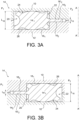
Figures 3A, 3B and4A shows embodiments of a gasket according to the invention. -
Figure 4B shows a gasket according to the prior art. -
Figure 5 shows another embodiment a gasket according to the invention. -
Figures 6A and6B show further embodiments of a gasket according to the invention. -
Figures 7A-7B are front views of various embodiments of gaskets according to the invention. -
Figures 8A-8B show embodiments of gaskets according to the invention in the case of a system using a single recess. -
Figures 9A-9C show further embodiments of gaskets according to the invention in the case of a system using a radial recess instead of an axial one. -
Figure 10 is a schematic diagram of a high voltage apparatus comprising a hole of a gas compartment closed by a flange and comprising a gasket according to the invention. -
Figures 11A and 11B show alternative shapes of the lip (s) . -
FIG. 1 illustrates an example of a system according to the invention to which a gasket according to the invention can apply. It comprises a portion of a high voltageapparatus comprising components 10, 10' assembled one to the other. Here, eachcomponent 10, 10' is represented as a cylindrical and tubular component and extends coaxial to a main axis AA' of the high voltage apparatus. It will be understood that the two components may be of any other shape; for example, they may be non-cylindrical tubular parts. - Alternatively, one of the components, or both of them, may be a non-tubular part, for example a
hole 100 of a gas compartment (figure 9 ) closed by aflange 101. - Alternatively, a gasket according to the invention can be used for example at the interface between two flanges. The following description is made with reference to tubular elements, but the invention applies to any other pair of elements, the interface of which must be sealed, in particular to:
- a gas like heptafluoroisobutyronitrile and/or heptafluoroisopropyl trifluoromethyl ketone (also named 2-butanone, 1,1,1,3,4,4,4-heptafluoro-3-(trifluoromethyl)- (CAS No 756-12-7)), possibly mixed with a gas or a dilution gas comprising at least CO2 and/O2 and/or N2 and/or and/or an oxygenated compound;
- or to a gas comprising at least CO2 and/O2 and/or N2 and/or an oxygenated compound, and/or water and/or water vapor.
- Said gas can have a pressure (P2) between 1 bar and 20 bar, for example 5 bar or 15 bar.
- As can be seen in more details in
fig. 2 , eachcomponent 10 comprises an end (or assembling) face 12 which faces, and possibly is connected, to the end (or assembling) face 12' of the other component 10'. - A sealing system for connecting the
components 10, 10' comprises acompression sealing gasket 14 that is arranged axially between thefaces 12, 12' of the twocomponents 10, 10' (or, in the example offigure 9 , between thehole 100 and the flange 101). The sealinggasket 14 extends substantially in a plane, which is perpendicular to axis AA'. In this example, and in some of the examples below, the sealing gasket has a circular symmetry around axis AA'. - The sealing system comprises tightening means 30, for example bolts and nuts or bolting means that press axially one
component 10 towards the other 10'. - The tightening means 30 also compress axially the sealing
gasket 14 to provide a gastight connection between the twocomponents 10, 10'. - According to the embodiment represented on
fig. 2 , theface 12, 12' of eachcomponent 10, 10' comprises anannular recess 16, 16' in which at least part of the sealinggasket 14, 14' is received. - The combined axial depth of the
recesses 16 and 16' is inferior to the height or the axial height of thegasket 14 before the twocomponents 10, 10' are assembled (said height or axial height is measured along axis AA' or along an axis perpendicular to the plane in which the gasket extends). If there is only one recess, forexample recess 16, then its axial depth is inferior to the axial height of thegasket 14 before the twocomponents 10, 10' are assembled. - The compression of the gasket 14' by the tightening means 30 produces an axial deformation of the
gasket 14 and maintains a pressure of thegasket 14 on the bottom of eachrecess 16, 16'. - As can be seen from
figures 3A, 3B and4A , thegasket 14 comprises amain body 141 made for example of a single material, for example of an elastomer like, as nonlimiting examples, unmodified butyl rubber or modified butyl rubber, for example chlorobutyl (CIIR) or bromobutyl (BIIR) rubber. - The permeability of this elastomer with respect to the gas intended to fill the
components 10, 10' results in a loss of gas during time. - As can be seen on
figures 3A, 3B and4A , a section of themain body 141 of thegasket 14, along an axial plane containing main axis AA', can have a general rectangular shape. - The
main body 141 of thegasket 14 comprises a radiallyouter side 20, a radiallyinner side 22 and two planar end faces 24, 26 that axially delimit thegasket 14 and connect theinner side 22 to theouter side 20. - One or more of the
sides figure 4A ) at least one protuberance orpeak 24a and at least one recess or depression orvalley recesses 16 and 16'. Alternatively, the sides and/or the end faces can have a different shape, or be rectilinear, as illustrated onfigure 5 (seesides - In order to reduce the permeability of the
gasket 14 to: - a gas like heptafluoroisobutyronitrile and/or heptafluoroisopropyl trifluoromethyl ketone (also named 2-butanone, 1,1,1,3,4,4,4-heptafluoro-3-(trifluoromethyl)- (CAS No 756-12-7)), possibly mixed with a gas or a dilution gas comprising at least CO2 and/O2 and/or N2 and/or and/or an oxygenated compound;
- or to a gas comprising at least CO2 and/O2 and/or N2 and/or an oxygenated compound, and/or water and/or water vapor,
at least one (or both) of theouter side 20 and theinner side 22 comprises a lip 142 (an inner lip on the example offigure 3A ) which can have a substantially rectangular in a plane containing the axis AA' (as can be seen onfigures 3A, 3B ,4A and5 ; other shapes are possible, for example at least partly rounded or at least partly circular or semi-circular, as can be seen onfigure 11A and 11B ). Preferably, the lip(s) and the main body have the same composition (see the above examples of materials of the main body, the lip(s) preferably being made of the same material as the main body), the composition of the gasket being thus homogeneous. - Said inner lip has a length I14 measured along an axis parallel to the AA' axis less than the length L14 of the main body along the same axis.
- For example: the extension (or thickness) L14 of the main body is between 3 mm and 25 mm and the extension (or thickness) I14 (<L14) of the lip is between 0.5 mm and 5 mm.
- The
lip 142 offers a smaller surface area S2 to gas permeating in a direction perpendicular to axis AA' than the surface area S1 of theinner side 22 of a known gasket (figure 4B ) not having alip 142. - Permeation (molecules going through the gasket) is linked to the surface area under pressure: due to its smaller extension l14 along the axis AA' the
lip 142 offers a reduced surface area S2 to permeation. - In the embodiments of
figures 3A and4A , the lip is an inner lip, oriented towards the part of the device having the highest pressure P2 in service conditions (the outside pressure of the device being P1 < P2). - In other embodiments, as on
figure 3B for example, the lip is an outer lip, oriented towards the outside part of the device, having the lowest pressure P1 in service conditions. A gasket provided with an outer lip as onfigure 3B is particularly efficient to limit or to prevent water permeation of H2O from outside the device provided with said gasket. - Temporary inversion of the pressure difference direction is permitted by the design of the invention but in a lower amplitude ((PI - P2)< 2 bar). Preferably, the device is able to withstand vacuum (0 bar absolute inside (P2) and 1 bar absolute outside (PI)) before filling.
- The width w of the gasket is measured in the plane containing the AA' axis but along an axis perpendicular to AA'; it is for example between 4 and 10 mm or 40 mm.
- The
main body 141 performs several functions: it is adapted to maintain a sufficient pressure on the surfaces to ensure tightness with consideration of thermal dilatations, ageing, manufacturing tolerances and environmental constraints. It also permits easier handling of the gasket during the assembly process. - Preferably, the
lip 142 usually has an average compression rate (for example between 15 % and 40%) which is higher than the average compression rate of the main body 141 (for example between 10 % and 25%). The respective recesses 161, 162 are preferably designed so that the lip is more compressed than the main body of the gasket. This ensures sufficient compression, preferably in all conditions and regarding the above mentioned constraints. It can be noted that in the main body those portions A1 (seefigure 4A ) having restrictions due to therecesses - The recess for a gasket according to the invention has:
- a first large parallelepipedal shape (for the main body of the gasket) having a length L16 measured along an axis parallel to the axis AA';
- and a second smaller parallelepipedal shape which has a length l16, also measured along an axis parallel to the AA', l16 < L16.
- Preferably the ratio l16/l14 is between 0.60 and 0.85 and/or the ratio L16/L14 is between 0.75 and 0.9;
- Generally a ratio l16/l14 < L16/L14 is preferred (for a higher compression rate on the lip than on the main body).
-
Figures 6A and6B show particular embodiments of a gasket system according to the invention, comprising two gaskets according to the invention in series: - a first (outer) gasket, which has (
figure 6A ) amain body 14a and an inner lip 14'a or (figure 6B ) amain body 14a, an outer lip 14'a1 and an inner lip 14'a ; - and a second (inner) gasket, which has a
main body 14b and an inner lip 14'b, the inner lip 14'a of the first (outer) gasket being connected to the outer side of themain body 14b of the second (inner) gasket. - In both embodiments of
figures 6A and6B , the inner gasket is on the side of the device having the highest pressure P2 in service conditions (the outside pressure of the device being P1 < P2). - The first (outer) gasket has a lateral extension (D14a on
figure 6A , D'14a onfigure 6B ) which is larger than the second (inner) gasket (D14b on bothfigures 6A and6B ). - These 2 gaskets are adapted to corresponding
double recesses figures 6A and6B . - The double structure of the gasket systems of
figures 6A and6B ensures a very high tightness with respect to the gases located on the pressure side of the device (at pressure P2 > P1). -
Figure 7A is a front view in a plane perpendicular to the axis (AA') (or a view in the plane of the gasket) of a circular or annular gasket according to the invention. It has an inner diameter D1 (the inner diameter if the lip 141) which can for example be comprised between, on the one hand, 40 mm or 50 mm or 100 mm and, on the other hand, 500 mm or even 1300 mm. Such large gaskets are more critical in terms of tightness than the usual smaller gasket (of diameter comprised between 10 mm and 40 mm) . - Alternatively, a gasket according to the invention can have in a plane perpendicular to the axis (AA') (or in the plane of the gasket) an elongated or oval or ellipsoidal shape (
figure 7B ), having a maximal inner dimension D2 which can for example be comprised between, on the one hand, 40 mm or 50 mm or 100 mm and, on the other hand, 500 mm or even 1300 mm. - In general (for any of the embodiments of a gasket according to the invention):
- the lip extends along the whole length of the inner or outer side of the main body of the gasket;
- and/or the lip is made of the same material as the main body.
- Variants of the invention are shown on
figures 8A, 9A and 9B , at the interface between twoparts 10, 10': these gaskets have a "L" shape, thelip 142 having aface 140, perpendicular to said AA' axis, extending in a same plane as one of the lateral end faces 24, 26 of themain body 142 of the gasket. -
Figure 8B shows the gasket offigure 8A in a corresponding recess having an "L" shape. In the embodiment offigure 8B , only one of the twoparts 10, 10' has a recess. - In the embodiment of
figure 9C , only the main body of the gasket, or part of said main body, offigure 9A or 9B is in a recess. As can be seen on this figure, the assembling faces of the two parts or of the two components are not contacting each other at least in an area surrounding the recess and/or the gasket (unlike the otherfigures 2 ,3A ,3B ,6A ,6B ). More generally (the gasket having an « L » shape or any other shape), at least in an area surrounding the recess and/or the gasket, at least part of the assembling faces of the two components: - may be contacting each other;
- or may not be contacting each other; in this last case, part of the gasket, for example one or more lip(s) or at least part of one or more lip(s), may not be in a recess, but may be for example between said assembling faces.
- These embodiment of
figures 8A, 8B ,9A-9C can be adapted to smaller gaskets, for example having an inner dimension or diameter of between 40 mm (or 50 mm) and 200 mm with a more compact implementation than the previously presented embodiments. They are able to replace O-rings and are easier to integrate than the gaskets described above in connection with the preceding figures. - As illustrated on
figures 9A-9C , the main body of a gasket according to the invention can have an extension (or thickness or axial height) L14 of the main body which is larger than the distance between itsinner side 22 and its outer side 20 (measured in a plane perpendicular to the axis AA' or in the plane of the gasket). This applies to an "L" shaped gasket, but also to any other embodiment. - A gasket according to the invention can be formed by injection of a non-vulcanized (or uncured) material into a mold, followed by a compression step.
- The invention applies for example to a switch, or to a circuit-breaker, or to a disconnector, or to a transformer, or to a surge arresters, or to a gas-insulated line .
Claims (15)
- A compression sealing gasket (14, 14') comprising a main body (141) of general planar extension, or extending in a plane, comprising an inner side (22, 32) and an outer side (20, 30), and end faces (24, 26, 34, 36), which delimit the gasket along an axis (AA') perpendicular to said plane, and connect the inner side and the outer side, made of an elastomer material, said main body having a 1st extension (L14), along said axis (AA'), at least one of said inner side and said outer side being provided with a lip (141) which has a 2nd extension (l14), along said axis (AA') perpendicular to said plane, less than the 1st extension (L14).
- A gasket (14, 14') according to claim 1, wherein said 1st extension (L14) is comprised between 3 mm and 25 mm.
- A gasket (14, 14') according to any of claims 1 or 2, wherein the 2nd extension (l14) is comprised between 0.5 mm and 5 mm.
- A gasket (14, 14') according to any of claims 1 to 3, wherein the gasket has a maximum inner dimension (D1 - D2) between 50 mm and 1300 mm.
- A gasket (14, 14') according to any of claims 1 to 4, wherein the lip (142) has an average compression rate higher than the main body (141).
- A gasket (14, 14') according to any of claims 1 to 5, wherein:- said outer side (20, 30) and said inner side (22, 32) are parallel and/or coaxial to each other;- and/or the gasket has in a plane perpendicular to said axis (AA') an annular or oval or ellipsoidal shape.
- A gasket (14, 14') according to any of claims 1 to 8, each of said inner side and said outer side being provided with a lip (14'a, 14'a1).
- A gasket (14, 14') according to any of claims 1 to 7, at least one of said end faces (24, 26, 34, 36) and of said outer side (20) and said inner side (22) has a wavy shape.
- A gasket (14, 14') according to any of claims 1 to 8, the lip (142) having a side, perpendicular to said (AA') axis, extending in a same plane as one of said end faces (24, 26, 34, 36).
- A compression sealing gasket system comprising two gaskets (14, 14') according to one of claims 1 to 9 in series, the lip (14'a) of one of said gaskets being connected to the inner side or to the outer side of the other one of said gaskets.
- A sealing system comprising two components (10, 10', 100, 101) of a gas insulated portion of a high or medium voltage apparatus, in which each of the components (10') comprises an assembling face (12', 102) that faces the assembling face (12, 101) of the other component (10), at least one of said assembling faces comprising at least one recess (16) and wherein a compression sealing gasket (14, 14') according to any of claims 1 to 9, or a compression sealing gasket system according to claim 10, is at least partly arranged in said at least one recess and is compressed between the assembling faces (12, 12', 101, 102) of the components (10, 10') .
- A sealing system according to claim 11, said gas insulated portion containing, or being intended to contain, a gas comprising at least:- heptafluoroisobutyronitrile and/or heptafluoroisopropyl trifluoromethyl ketone (also named 2-butanone, 1,1,1,3,4,4,4-heptafluoro-3-(trifluoromethyl)- (CAS No 756-12-7)), possibly mixed with a gas or a dilution gas comprising at least CO2 and/O2 and/or N2 and/or and/or an oxygenated compound;- or to a gas comprising at least CO2 and/O2 and/or N2 and/or an oxygenated compound and/or water vapor;- and/or water.
- A sealing system according to claim 11 or 12, said gas insulated portion forming part of a switch, or of a circuit-breaker, or of a disconnector, or of a transformer, or of a surge arresters, or of a gas-insulated line.
- A method for insulating a gas insulated portion of a high or medium voltage apparatus, said portion containing a gas comprising at least:- heptafluoroisobutyronitrile and/or heptafluoroisopropyl trifluoromethyl ketone (also named 2-butanone, 1,1,1,3,4,4,4-heptafluoro-3-(trifluoromethyl)- (CAS No 756-12-7)), possibly mixed with a gas or a dilution gas comprising at least CO2 and/O2 and/or N2 and/or and/or an oxygenated compound;- or to a gas comprising at least CO2 and/O2 and/or N2 and/or an oxygenated compound and/or water vapor;- and/or water,
said gas insulated portion comprising a sealing system according to claim 12 or 13. - A method according to claim 14, wherein said gas is contained in said apparatus at a pressure between 1 bar and 20 bar.
Priority Applications (7)
| Application Number | Priority Date | Filing Date | Title |
|---|---|---|---|
| EP22306053.4A EP4306825A1 (en) | 2022-07-13 | 2022-07-13 | Improved compression sealing gasket and sealing system |
| US18/881,496 US12618472B2 (en) | 2022-07-13 | 2023-07-13 | Compression sealing gasket and sealing system |
| PCT/EP2023/069467 WO2024013289A1 (en) | 2022-07-13 | 2023-07-13 | Improved compression sealing gasket and sealing system |
| KR1020257004580A KR20250037519A (en) | 2022-07-13 | 2023-07-13 | Improved compression sealing gasket and sealing system |
| JP2025501284A JP2025523667A (en) | 2022-07-13 | 2023-07-13 | Improved compression seal gasket and sealing system |
| CA3261594A CA3261594A1 (en) | 2022-07-13 | 2023-07-13 | Improved compression sealing gasket and sealing system |
| CN202380053335.7A CN119546887A (en) | 2022-07-13 | 2023-07-13 | Improved compression seal gasket and sealing system |
Applications Claiming Priority (1)
| Application Number | Priority Date | Filing Date | Title |
|---|---|---|---|
| EP22306053.4A EP4306825A1 (en) | 2022-07-13 | 2022-07-13 | Improved compression sealing gasket and sealing system |
Publications (1)
| Publication Number | Publication Date |
|---|---|
| EP4306825A1 true EP4306825A1 (en) | 2024-01-17 |
Family
ID=82846201
Family Applications (1)
| Application Number | Title | Priority Date | Filing Date |
|---|---|---|---|
| EP22306053.4A Pending EP4306825A1 (en) | 2022-07-13 | 2022-07-13 | Improved compression sealing gasket and sealing system |
Country Status (7)
| Country | Link |
|---|---|
| US (1) | US12618472B2 (en) |
| EP (1) | EP4306825A1 (en) |
| JP (1) | JP2025523667A (en) |
| KR (1) | KR20250037519A (en) |
| CN (1) | CN119546887A (en) |
| CA (1) | CA3261594A1 (en) |
| WO (1) | WO2024013289A1 (en) |
Cited By (1)
| Publication number | Priority date | Publication date | Assignee | Title |
|---|---|---|---|---|
| EP4607066A1 (en) * | 2024-02-21 | 2025-08-27 | General Electric Technology GmbH | Flat compression sealing gasket and sealing system comprising same |
Citations (5)
| Publication number | Priority date | Publication date | Assignee | Title |
|---|---|---|---|---|
| DE8800117U1 (en) * | 1988-01-08 | 1988-03-10 | APV-Rosista GmbH, 4750 Unna | Flange connection with a seal |
| DE4201535A1 (en) * | 1992-01-22 | 1993-07-29 | Apv Rosista Gmbh | Flange coupling with aseptic region and elastic seal - has shaped seal seating to compress seal for flush alignment with pipe walls. |
| DE102004018587A1 (en) * | 2004-04-16 | 2005-11-03 | Gea Wiegand Gmbh | Flange connection for use in high hygiene conditions has sealing ring between flanges with thickness of undeformed sealing ring between sealing faces tapering radially away from inner generated surface of flange |
| EP3330580A1 (en) * | 2016-12-05 | 2018-06-06 | ABB Schweiz AG | Use of a coated o-ring for a gas-insulated electric equipment |
| EP3502521A1 (en) * | 2017-12-20 | 2019-06-26 | Tetra Laval Holdings & Finance S.A. | A seal and a tubular heat exchanger using such seal |
Family Cites Families (29)
| Publication number | Priority date | Publication date | Assignee | Title |
|---|---|---|---|---|
| US2599767A (en) * | 1946-04-01 | 1952-06-10 | Joe G Long | Rubber seal joint |
| US2789844A (en) * | 1952-10-20 | 1957-04-23 | Ladish Co | Sealed joint for flanged pipe with opposed packing grooves |
| US3191949A (en) * | 1961-10-26 | 1965-06-29 | Parker Hannifin Corp | Sealed joint and gasket therefor |
| US3620539A (en) * | 1968-08-23 | 1971-11-16 | Us Army | Moisture-proof wire holder |
| FR2102523A5 (en) * | 1970-08-06 | 1972-04-07 | Remy & Cie E P | |
| US3746348A (en) * | 1971-01-15 | 1973-07-17 | Parker Hannifin Corp | Sealing ring with retaining means |
| US3819211A (en) * | 1971-05-05 | 1974-06-25 | Detroit Stoker Co | Conveyor system |
| US3990711A (en) * | 1975-05-09 | 1976-11-09 | Hill Ralph W | Restrained elastomeric seal ring means |
| CA2127957A1 (en) * | 1993-09-29 | 1995-03-30 | Gerald A. Babuder | Clamped flange fitting and assembly |
| JP3576229B2 (en) * | 1994-10-24 | 2004-10-13 | 塩野義製薬株式会社 | Gasket for sanitary piping and method of manufacturing the same |
| US5947533A (en) * | 1996-08-02 | 1999-09-07 | Fisher; Ronald K. | Gasket assembly with elastomer expansion area |
| US6039319A (en) * | 1997-02-24 | 2000-03-21 | Swagelok Company | Hygienic fitting with thermal expansion area for gasket |
| JPH10257619A (en) * | 1997-03-12 | 1998-09-25 | Meidensha Corp | Gas insulated switchgear |
| US6073969A (en) * | 1998-04-02 | 2000-06-13 | Tri-Clover, Inc. | Pipe connection for pipes having dissimilar end ferrules |
| EP1837564A1 (en) * | 2006-03-23 | 2007-09-26 | Carl Freudenberg KG | Sealing ring |
| US8333386B2 (en) * | 2007-03-27 | 2012-12-18 | Ckd Corporation | Seal structure for connection sections and seal member used for the same |
| WO2010144500A1 (en) * | 2009-06-08 | 2010-12-16 | Butte Jeffrey C | Self-aligning sanitary pipe joints and related systems |
| DE102012101384A1 (en) * | 2012-02-21 | 2013-08-22 | Elringklinger Ag | Flat seal i.e. cylinder head seal, for e.g. ship, has support elements measured such that support elements are deformed vertical to plane by pressing forces, and seal lip with pressure for sealing function resting against component in seal |
| FR2997223B1 (en) * | 2012-10-22 | 2016-01-29 | Alstom Technology Ltd | ELECTRICAL EQUIPMENT COMPRISING A SUPPORT OF A CONDUCTOR BETWEEN TWO ENVELOPE PORTIONS |
| CN108368937B (en) * | 2015-12-24 | 2020-07-10 | Nok株式会社 | Gasket and method of making and operating same |
| RU2623587C1 (en) * | 2016-01-28 | 2017-06-28 | Общество с ограниченной ответственностью "ИЛЬМА" | Sealing gasket and method for its manufacturing |
| DE102016105047A1 (en) * | 2016-03-18 | 2017-09-21 | Gea Mechanical Equipment Gmbh | Sealing arrangement for sealing a gap |
| US11162589B2 (en) * | 2018-10-26 | 2021-11-02 | Parker-Hannifin Corporation | Exclusion and pulsation seal for hydraulic fracturing pump |
| JP2020076450A (en) * | 2018-11-07 | 2020-05-21 | 本田技研工業株式会社 | Seal structure |
| JP6999614B2 (en) * | 2019-07-26 | 2022-01-18 | 株式会社バルカー | Support member |
| CA3109408A1 (en) * | 2020-02-20 | 2021-08-20 | Lavelle Industries, Inc. | Universal gasket |
| US11486494B2 (en) * | 2020-09-23 | 2022-11-01 | Dana Automotive Systems Group, Llc | Elastomeric seal for an enclosure |
| US20220373088A1 (en) * | 2021-05-21 | 2022-11-24 | Scican Ltd. | Door seal |
| EP4607066A1 (en) * | 2024-02-21 | 2025-08-27 | General Electric Technology GmbH | Flat compression sealing gasket and sealing system comprising same |
-
2022
- 2022-07-13 EP EP22306053.4A patent/EP4306825A1/en active Pending
-
2023
- 2023-07-13 US US18/881,496 patent/US12618472B2/en active Active
- 2023-07-13 CA CA3261594A patent/CA3261594A1/en active Pending
- 2023-07-13 KR KR1020257004580A patent/KR20250037519A/en active Pending
- 2023-07-13 WO PCT/EP2023/069467 patent/WO2024013289A1/en not_active Ceased
- 2023-07-13 JP JP2025501284A patent/JP2025523667A/en active Pending
- 2023-07-13 CN CN202380053335.7A patent/CN119546887A/en active Pending
Patent Citations (5)
| Publication number | Priority date | Publication date | Assignee | Title |
|---|---|---|---|---|
| DE8800117U1 (en) * | 1988-01-08 | 1988-03-10 | APV-Rosista GmbH, 4750 Unna | Flange connection with a seal |
| DE4201535A1 (en) * | 1992-01-22 | 1993-07-29 | Apv Rosista Gmbh | Flange coupling with aseptic region and elastic seal - has shaped seal seating to compress seal for flush alignment with pipe walls. |
| DE102004018587A1 (en) * | 2004-04-16 | 2005-11-03 | Gea Wiegand Gmbh | Flange connection for use in high hygiene conditions has sealing ring between flanges with thickness of undeformed sealing ring between sealing faces tapering radially away from inner generated surface of flange |
| EP3330580A1 (en) * | 2016-12-05 | 2018-06-06 | ABB Schweiz AG | Use of a coated o-ring for a gas-insulated electric equipment |
| EP3502521A1 (en) * | 2017-12-20 | 2019-06-26 | Tetra Laval Holdings & Finance S.A. | A seal and a tubular heat exchanger using such seal |
Non-Patent Citations (1)
| Title |
|---|
| CAS , no. 756-12-7 |
Cited By (1)
| Publication number | Priority date | Publication date | Assignee | Title |
|---|---|---|---|---|
| EP4607066A1 (en) * | 2024-02-21 | 2025-08-27 | General Electric Technology GmbH | Flat compression sealing gasket and sealing system comprising same |
Also Published As
| Publication number | Publication date |
|---|---|
| CN119546887A (en) | 2025-02-28 |
| US12618472B2 (en) | 2026-05-05 |
| CA3261594A1 (en) | 2024-01-18 |
| KR20250037519A (en) | 2025-03-17 |
| US20250305584A1 (en) | 2025-10-02 |
| WO2024013289A1 (en) | 2024-01-18 |
| JP2025523667A (en) | 2025-07-23 |
Similar Documents
| Publication | Publication Date | Title |
|---|---|---|
| US12104697B2 (en) | Compression sealing gasket and sealing system | |
| CN116368702B (en) | Flange design for high voltage gas insulated switchgear (GIS), busbars and pipelines (GIL) | |
| US20130213937A1 (en) | Gas insulated switchgear | |
| US12618472B2 (en) | Compression sealing gasket and sealing system | |
| US20020063111A1 (en) | Gas-filled switching apparatus | |
| US20250267814A1 (en) | Flat compression sealing gasket and sealing system comprising same | |
| EP3330580A1 (en) | Use of a coated o-ring for a gas-insulated electric equipment | |
| KR102086949B1 (en) | The busbar for eco-friendly gas insulated load break switch to possess modular design of insulation parts | |
| JP2004220922A (en) | Gas insulated switchgear | |
| US20260009470A1 (en) | Improved compression sealing gasket and sealing system | |
| CN219874776U (en) | Air charging cabinet, switch equipment and electrical device | |
| US20130001200A1 (en) | Vacuum Valve and Switchgear Equipped with Said Vacuum Valve | |
| US11742640B2 (en) | Medium voltage electrical apparatus tank | |
| KR100960075B1 (en) | Polymer Insulated Multi-Circuit Switchgear for Underground Power Distribution Lines | |
| CN112053897B (en) | Layered high-voltage vacuum switch tube | |
| CN120674217B (en) | Sealing structure of voltage transformers and gas-insulated composite voltage transformers | |
| JP4119441B2 (en) | Gas insulated switchgear | |
| CN210296247U (en) | Sealing structure suitable for outdoor 10kV SF6 circuit breaker | |
| RU2405225C2 (en) | Dielectric insulating gasket for vacuum tube | |
| JP2013230062A (en) | Gas insulated electric apparatus | |
| WO2013113374A1 (en) | Removable under pressure transportation supports for pure gas wall bushings | |
| WO2025067624A1 (en) | Gas tight enclosure for a gas-insulated medium-volatage or high-voltage apparatus | |
| WO2022254522A1 (en) | Gas-insulated apparatus | |
| CN111396555A (en) | Special-shaped sealing ring | |
| CN121483846A (en) | A high-voltage gas current transformer |
Legal Events
| Date | Code | Title | Description |
|---|---|---|---|
| PUAI | Public reference made under article 153(3) epc to a published international application that has entered the european phase |
Free format text: ORIGINAL CODE: 0009012 |
|
| STAA | Information on the status of an ep patent application or granted ep patent |
Free format text: STATUS: THE APPLICATION HAS BEEN PUBLISHED |
|
| AK | Designated contracting states |
Kind code of ref document: A1 Designated state(s): AL AT BE BG CH CY CZ DE DK EE ES FI FR GB GR HR HU IE IS IT LI LT LU LV MC MK MT NL NO PL PT RO RS SE SI SK SM TR |
|
| STAA | Information on the status of an ep patent application or granted ep patent |
Free format text: STATUS: REQUEST FOR EXAMINATION WAS MADE |
|
| 17P | Request for examination filed |
Effective date: 20240717 |
|
| RBV | Designated contracting states (corrected) |
Designated state(s): AL AT BE BG CH CY CZ DE DK EE ES FI FR GB GR HR HU IE IS IT LI LT LU LV MC MK MT NL NO PL PT RO RS SE SI SK SM TR |
|
| STAA | Information on the status of an ep patent application or granted ep patent |
Free format text: STATUS: EXAMINATION IS IN PROGRESS |
|
| 17Q | First examination report despatched |
Effective date: 20250320 |
|
| RAP3 | Party data changed (applicant data changed or rights of an application transferred) |
Owner name: GE VERNOVA TECHNOLOGY GMBH |
|
| GRAP | Despatch of communication of intention to grant a patent |
Free format text: ORIGINAL CODE: EPIDOSNIGR1 |
|
| STAA | Information on the status of an ep patent application or granted ep patent |
Free format text: STATUS: GRANT OF PATENT IS INTENDED |