EP4306745B1 - Stützwagen für ein beckenabdecksystem - Google Patents
Stützwagen für ein beckenabdecksystem Download PDFInfo
- Publication number
- EP4306745B1 EP4306745B1 EP23183602.4A EP23183602A EP4306745B1 EP 4306745 B1 EP4306745 B1 EP 4306745B1 EP 23183602 A EP23183602 A EP 23183602A EP 4306745 B1 EP4306745 B1 EP 4306745B1
- Authority
- EP
- European Patent Office
- Prior art keywords
- rotation
- drive
- pool
- support
- winding drum
- Prior art date
- Legal status (The legal status is an assumption and is not a legal conclusion. Google has not performed a legal analysis and makes no representation as to the accuracy of the status listed.)
- Active
Links
Images


Classifications
-
- E—FIXED CONSTRUCTIONS
- E04—BUILDING
- E04H—BUILDINGS OR LIKE STRUCTURES FOR PARTICULAR PURPOSES; SWIMMING OR SPLASH BATHS OR POOLS; MASTS; FENCING; TENTS OR CANOPIES, IN GENERAL
- E04H4/00—Swimming or splash baths or pools
- E04H4/06—Safety devices; Coverings for baths
- E04H4/10—Coverings of flexible material
- E04H4/101—Coverings of flexible material wound-up on a fixed axis
-
- E—FIXED CONSTRUCTIONS
- E04—BUILDING
- E04H—BUILDINGS OR LIKE STRUCTURES FOR PARTICULAR PURPOSES; SWIMMING OR SPLASH BATHS OR POOLS; MASTS; FENCING; TENTS OR CANOPIES, IN GENERAL
- E04H4/00—Swimming or splash baths or pools
- E04H4/06—Safety devices; Coverings for baths
- E04H4/08—Coverings consisting of rigid elements, e.g. coverings composed of separate or connected elements
- E04H4/082—Coverings consisting of rigid elements, e.g. coverings composed of separate or connected elements composed of flexibly or hingedly-connected slat-like elements, which may or may not be wound-up on a fixed axis
Definitions
- the present invention relates to a support trolley for a pool covering system, and to a pool covering system comprising such a support trolley.
- the driven part of the second overrunning clutch which is rotationally secured to the rolling elements, is likely to be driven in rotation, depending on the diameters of the rolling elements and the diameter of the winding drum which changes during the phase of rolling up the pool cover, at a rotational speed which may induce the second overrunning clutch to switch to the engaged state.
- a switch of the second overrunning clutch to the engaged state when rolling up the pool cover while the rolling elements are rolling on the rolling surfaces arranged on either side of the pool, is detrimental to the quality of the winding of the pool cover, but also to the reliability of the drive mechanism, since it may induce wear or even breakage of certain elements of the drive mechanism, such as the first and second overrunning clutches and the endless transmission element.
- EP 3 318 700 A1 , EP 3 739 149 A1 And FR 2 908 402 A1 also disclose support carts according to the state of the art.
- the present invention aims to remedy all or part of these drawbacks.
- the technical problem underlying the invention is therefore to provide a support trolley for a pool covering system which is of simple and reliable structure, whilst ensuring easy and reliable rolling and unrolling of a pool cover.
- the winding drum is rotated in the blanket winding direction via the coupling member, thereby inducing a winding the pool cover around the winding drum and thus moving the support part in a direction of movement corresponding to an opening of the pool.
- the drive wheels When the drive motor is rotated in the second motor rotation direction, the drive wheels are rotated in the pool closing direction via the coupling member and roll on the two rolling surfaces arranged on either side of the pool, which causes the support part to move in a direction of movement corresponding to a pool closing. Such a movement of the support part induces traction on the pool cover, which causes the winding drum to rotate in the cover unwinding direction and thus unwinds the pool cover.
- Such a configuration of the rotation drive device, and in particular of the coupling mechanism, ensures in particular optimum winding of the pool cover around the winding drum.
- the support trolley may further have one or more of the following features, taken alone or in combination.
- the direction of movement is substantially parallel to the axis of rotation of the winding drum.
- the at least one coupling mechanism further comprises a first toothed wheel which is rotationally fixed to the winding drum and a second toothed wheel which is rotationally fixed to the respective drive wheel, the coupling member being configured to be rotationally coupled to the first toothed wheel when the coupling member occupies the first engaged state and to be rotationally coupled to the second toothed wheel when the coupling member occupies the second engaged state.
- the first toothed wheel extends substantially coaxially with the winding drum.
- the second toothed wheel extends substantially coaxially with the respective drive wheel.
- the first and second toothed wheels of the at least one coupling mechanism extend respectively in two extension planes which are substantially parallel and which are offset relative to each other according to the direction of movement of the coupling member.
- the coupling member is configured to extend in the extension plane of the respective first gear wheel when the coupling member occupies the first engaged state, and to extend in the extension plane of the respective second gear wheel when the coupling member occupies the second engaged state.
- the at least one coupling mechanism comprises at least one intermediate toothed wheel mounted rotatably on the respective lateral support frame and configured to rotatably couple the coupling member with the respective first toothed wheel when the coupling member occupies the first engaged state.
- the rotation drive device comprises a drive shaft which is rotationally coupled to the drive motor and which comprises two end portions opposite one another, the coupling member being mechanically connected to a respective end portion of the drive shaft.
- the coupling member is carried by the respective end portion of the drive shaft.
- the two end portions of the drive shaft are respectively supported by the two lateral support frames.
- the drive shaft extends substantially parallel to the winding drum.
- the coupling member comprises a mounting part, for example tubular, mounted on the respective end portion of the drive shaft, and a coupling part comprising peripheral teeth.
- the peripheral toothing of the coupling part is configured to be rotationally coupled to the respective first gear wheel when the coupling member occupies the first engaged state, and to be rotationally coupled to the respective second gear wheel when the coupling member occupies the second engaged state.
- the mounting part comprises at least one connecting groove which extends helically around a central longitudinal axis of the drive shaft and in which a connecting lug provided on the respective end portion of the drive shaft is slidably mounted.
- the connecting groove is through and forms a connecting slot.
- the drive motor is rotationally coupled to a central portion of the drive shaft which is located substantially equidistant from the first and second side support frames.
- the drive motor is arranged in a central portion of the support part.
- the axes of rotation of the two drive wheels extend substantially parallel to the axis of rotation of the winding drum.
- the axes of rotation of the two drive wheels are substantially colinear.
- the support carriage comprises a control unit configured to control the operation of the drive motor.
- the rotation drive device comprises two coupling mechanisms provided respectively in the two lateral support frames.
- the two coupling members of the two coupling mechanisms are connected respectively to the two opposite end portions of the drive shaft.
- the rotation drive device comprises two drive shafts, each coupling member being connected to an end portion of a respective drive shaft.
- the rotational drive device comprises two drive motors, each drive shaft being rotationally coupled to a respective drive motor.
- the support carriage extends in a general direction of extension.
- the support carriage further comprises an anti-imbalance device configured to exert a resistive torque on the winding drum.
- an anti-imbalance device configured to exert a resistive torque on the winding drum.
- the present invention further relates to a pool covering system, comprising a support trolley according to the invention, and a pool cover configured to be rolled up around the winding drum.
- the pool cover comprises a tarpaulin and support bars attached to the tarpaulin and configured to rest on opposite edges of the basin.
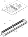
- FIGS. 1 to 12 represent a basin covering system 2 intended to cover a basin 3, such as a swimming pool.
- the pool covering system 2 comprises a pool cover 4 having two transverse edges 5 opposite each other and two longitudinal edges 6 also opposite each other.
- One of the transverse edges 5 of the pool cover 4 is intended to be fixed to a transverse edge of the pool 3, for example, according to the embodiment shown in the figure 1 , the transverse edge opposite the stairs providing access to pool 3.
- the pool cover 4 comprises a tarpaulin 4.1 which is flexible and which can for example be made of PVC, and support bars 4.2 fixed to the tarpaulin 4.1 and configured to rest on opposite edges of the pool 3, and more particularly on the longitudinal edges of the pool 3.
- Each support bar 4.2 can for example be inserted into a respective sheath provided on the tarpaulin.
- Such a pool cover 4 is also called a bar cover or bar tarpaulin.
- the pool cover 4 could have a different structure, and for example be made in the form of a slatted apron.
- the basin covering system 2 further comprises a support carriage 7 extending in a general direction of extension De.
- the support carriage 7 comprises a support portion 8 configured to be movable in translation in a translation direction Dt and in a first direction of movement S1 and a second direction of movement S2 opposite the first direction of movement S1.
- the translation direction Dt of the support portion 8 advantageously extends perpendicular to the general direction of extension De of the support carriage 7 and parallel to the direction of extension of the basin 3.
- the support part 8 comprises two lateral support frames 9 intended to move respectively along two opposite lateral edges of the basin, and more particularly along two longitudinal edges of the basin 3.
- the support part 8 could optionally further comprise one or more reinforcing elements, such as reinforcing beams, connecting the two lateral support frames 9.
- the support carriage 7 also comprises a winding drum 11 configured to wind and unwind the pool cover 4 between a covering position in which the pool cover 4 is unwound and covers all or substantially all of the pool 3, and a release position in which the pool cover 4 is rolled up and releases access to the pool 3.
- a winding drum 11 configured to wind and unwind the pool cover 4 between a covering position in which the pool cover 4 is unwound and covers all or substantially all of the pool 3, and a release position in which the pool cover 4 is rolled up and releases access to the pool 3.
- the winding drum 11 comprises two end portions opposite each other and respectively supported by the two lateral support frames 9.
- the winding drum 11 is mounted to be movable in rotation relative to the support part 8 about an axis of rotation A (see FIG. figure 7 ) extending perpendicular to the translation direction Dt and in a cover winding direction SE and a cover unwinding direction SD opposite to the cover winding direction SE.
- the support part 8 comprises a protective cover 12 mounted on the two side support frames 9, and configured to cover and protect the winding drum 11.
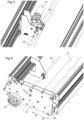
- the support carriage 7 further comprises two drive wheels 13 mounted rotatably respectively on the two lateral support frames 9 around axes of rotation which extend parallel to the axis of rotation A of the winding drum 11, and which may for example be colinear.
- the two drive wheels 13 are configured to roll respectively on two rolling surfaces arranged on either side of the basin 3 and extending more particularly respectively along the longitudinal edges of the basin 3.
- each drive wheel 13 comprises a tread, for example made of plastic.
- the support carriage 7 further comprises two rolling elements 14, such as casters or rollers, having axes of rotation extending parallel to the axis of rotation A of the winding drum 11, and configured to roll respectively on the two rolling surfaces arranged on either side of the basin 3.
- the rolling elements 14 are offset relative to the drive wheels 13 in the translation direction Dt. Such an arrangement of the rolling elements 14 and the drive wheels 13 ensures great stability for the support carriage 7.
- the support carriage 7 also comprises a rotation drive device configured to rotate the winding drum 11 in the cover winding direction SE and to rotate the two drive wheels 13 in a basin closing direction.
- the rotation drive device comprises a drive motor 15 and a drive shaft 16 which is rotatably coupled to the drive motor 15.
- the drive shaft 16 extends parallel to the winding drum 11 and comprises two end portions opposite each other which are respectively supported by the two lateral support frames 9.
- the drive motor 15 is arranged in a central portion of the support part 8, is covered by the protective cover 12, and is rotatably coupled to a central portion of the drive shaft 16 which is located substantially equidistant from the first and second lateral support frames 9.
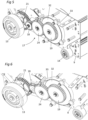
- the rotary drive device further comprises two coupling mechanisms 17 provided respectively in the two lateral support frames 9.
- Each coupling mechanism 17 comprises a coupling member 18, such as a coupling dog, mechanically connected to a respective end portion of the drive shaft 16, and more particularly carried by the respective end portion of the drive shaft 16.
- each member coupling 18 comprises a mounting part 18.1, for example tubular, fitted onto the respective end portion of the drive shaft, and a coupling part 18.2 coaxial with the respective mounting part 18.1 and comprising peripheral teeth.
- Each coupling mechanism 17 further comprises a first gear wheel 19 which is rotationally fixed to the winding drum 11, and a second gear wheel 21 which is rotationally fixed to the respective drive wheel 13.
- the first gear wheel 19 extends coaxially with the winding drum 11, and the second gear wheel 21 extends coaxially with the respective drive wheel 13.
- the first and second gear wheels 19, 21 of each coupling mechanism 17 extend respectively in two respective extension planes which are substantially parallel and which are offset from each other along a central longitudinal axis of the drive shaft 16.
- Each coupling member 18 is more particularly movable relative to the respective lateral support frame 9 in a direction of movement Dd which is parallel to the central longitudinal axis of the drive shaft 16 and between a first engaged state (see figures 5 , 8 And 10 ) in which the coupling member 18 extends in the extension plane of the respective first gear wheel 19 and the peripheral toothing of the respective coupling part 18.2 is rotatably coupled to the respective first gear wheel 19, and a second engaged state (see the figures 6 , 9 And 11 ) in which the coupling member 18 extends in the extension plane of the respective second gear wheel 21 and the peripheral toothing of the respective coupling part 18.2 is rotatably coupled to the respective second gear wheel 21.
- the coupling members 18 are configured to rotatably couple the drive shaft 16 to the winding drum 11 and to uncouple the drive shaft 16 from the drive wheels 13 when the coupling members 18 occupy the first engaged state, and are configured to rotatably couple the drive shaft 16 to the drive wheels 13 and uncouple the drive shaft 16 from the winding drum 11 when the coupling members 18 occupy the second engaged state.
- each coupling member 18 comprises a pair of connecting grooves 22 which each extend helically around the central longitudinal axis of the drive shaft 16 and in each of which is slidably mounted a respective connecting lug 23 provided on the respective end portion of the drive shaft 16.
- Each connecting groove 22 may for example be through, and thus form a connecting slot, and each connecting lug 23 may for example extend radially relative to the central longitudinal axis of the drive shaft 16.
- the two connecting lugs provided on each end portion of the drive shaft 16 are diametrically opposed.
- each connecting groove 22 has a first cam surface 22.1 configured to cooperate with the respective connecting lug 23 when the drive shaft 16 is rotated in a first direction of rotation, and a second cam surface 22.2 configured to cooperate with the respective connecting lug 23 when the drive shaft 16 is rotated in a second direction of rotation.
- each connecting lug 23 slides on the respective first cam surface 22.1, and, since the respective coupling part 18.2 is rotatably coupled with the respective second gear wheel 21, the respective coupling member 18 is moved in translation in the direction of movement Dd until reaching the first engaged state which corresponds to a position in which said connecting lug 23 abuts against a first end of the respective connecting groove 22 (see FIG. figure 10 ).
- each connecting lug 23 slides on the respective second cam surface 22.2, and, since the respective coupling part 18.2 is rotatably coupled with the respective first gear wheel 19, the respective coupling member 18 is moved in translation in the direction of movement Dd until reaching the second engaged state which corresponds to a position in which said connecting lug 23 abuts against a second end of the respective connecting groove 22 (see FIG. figure 11 )
- each coupling mechanism 17 comprises an intermediate toothed wheel 24 mounted rotatably on the respective lateral support frame 9 and configured to rotatably couple the coupling member 18 with the respective first toothed wheel 19 when the coupling member 18 occupies the first engaged state.
- the drive wheels 13 are rotated in the pool closing direction by means of the coupling member 18 and roll on the two rolling surfaces arranged on either side of the pool 3, which causes a displacement of the support part 8 in the first direction of movement S1.
- Such a displacement of the support part 8 induces a traction on the pool cover 4, which causes a rotation of the winding drum 11 in the cover unwinding direction SD and thus an unwinding of the pool cover 4.
- the support carriage 7 further comprises a control unit configured to control in particular the operation of the drive motor 15, and may also comprise one or more photovoltaic panels configured to electrically supply in particular the control unit and the drive motor 15. Each photovoltaic panel may for example be mounted on an upper face of the protective cover 12.
- the support carriage 7 further comprises an anti-imbalance device 31 configured to exert a resistive torque, directly or indirectly, on the winding drum 11, such that, when a support bar 4.2 leaves the winding drum 11 during the unwinding of the pool cover 4, the mass of said support bar 4.2 does not cause an acceleration of the rotation of the winding drum 11 and therefore a noisy impact of said support bar 4.2 against the pool 3.
- an anti-imbalance device 31 configured to exert a resistive torque, directly or indirectly, on the winding drum 11, such that, when a support bar 4.2 leaves the winding drum 11 during the unwinding of the pool cover 4, the mass of said support bar 4.2 does not cause an acceleration of the rotation of the winding drum 11 and therefore a noisy impact of said support bar 4.2 against the pool 3.
- the anti-imbalance device 31 comprises a braking roller 32 which extends substantially coaxially with the winding drum 11 and which is integral in rotation with the winding drum 11, a friction belt 33 configured to cooperate by friction with an external peripheral wall of the braking roller 32 and a tensioning device 34 configured to tension the friction belt 33.
- the tensioning device 34 may for example comprise a tension spring 35 configured to exert a tensile force on the friction belt 33 which is oriented substantially radially relative to the axis of rotation A.
- the rotation drive device could comprise two drive shafts 16, each coupling member 18 then being mechanically connected to an end portion of a respective drive shaft 16.
- the rotation drive device could comprise two drive motors 15, each drive shaft 16 then being coupled in rotation to a respective drive motor 15.
Landscapes
- Engineering & Computer Science (AREA)
- Architecture (AREA)
- Civil Engineering (AREA)
- Structural Engineering (AREA)
- Handcart (AREA)
- Storing, Repeated Paying-Out, And Re-Storing Of Elongated Articles (AREA)
Claims (16)
- Tragschlitten (7) für ein Beckenabdeckungssystem (2), wobei der Tragschlitten (7) Folgendes umfasst:- ein Tragteil (8), das dazu konfiguriert ist, in Bezug auf das Becken in einer Translationsrichtung (Dt) translatorisch bewegbar zu sein, wobei das Tragteil (8) zwei seitliche Tragrahmen (9) umfasst, die dazu bestimmt sind, sich jeweils entlang zweier gegenüberliegender Seitenkanten das Becken zu bewegen,- eine Wickeltrommel (11), die dazu konfiguriert ist, eine Beckenabdeckung (4) zwischen einer Abdeckposition, in der die Beckenabdeckung (4) ein Becken abdeckt, und einer Freigabeposition, in der die Beckenabdeckung (4) den Zugang zum Becken freigibt, aufzuwickeln und abzuwickeln, wobei die Wickeltrommel (11) zwei einander gegenüberliegende Endabschnitte umfasst und jeweils von den beiden seitlichen Tragrahmen (9) getragen wird, wobei die Wickeltrommel (11) in Bezug auf das Tragteil (8) um eine Drehachse (A), die sich quer zur Translationsrichtung (Dt) und in einer Abdeckungsaufwickelrichtung (SE) und einer Abdeckungsabwickelrichtung (SD), die entgegengesetzt zur Abdeckungsaufwickelrichtung (SE) ist, erstreckt, drehbeweglich montiert ist,- zwei Antriebsräder (13), die jeweils auf den beiden seitlichen Tragrahmen (9) drehbeweglich montiert sind und die dazu konfiguriert sind, jeweils auf zwei Rollflächen, die auf beiden Seiten des Beckens angeordnet sind, zu rollen, und- eine Drehantriebsvorrichtung, die dazu konfiguriert ist, die Wickeltrommel (11) und die beiden Antriebsräder (13) anzutreiben, wobei die Drehantriebsvorrichtung einen Antriebsmotor (15) und mindestens einen Kopplungsmechanismus (17) umfasst, der mindestens teilweise in einem der seitlichen Tragrahmen (9) angeordnet ist, wobei der mindestens eine Kopplungsmechanismus (17) ein Kopplungselement (18) umfasst, das in Bezug auf den jeweiligen seitlichen Tragrahmen (9) in einer Bewegungsrichtung (Dd) und zwischen einem ersten eingerückten Zustand, in dem das Kopplungselement (18) dazu konfiguriert ist, den Antriebsmotor (15) drehbar mit der Wickeltrommel (11) zu koppeln, und vom jeweiligen Antriebsrad (13) entkoppelt ist, und einem zweiten eingerückten Zustand, in dem das Kopplungselement (18) dazu konfiguriert ist, den Antriebsmotor (15) drehbar mit dem jeweiligen Antriebsrad (13) zu koppeln, und von der Wickeltrommel (11) entkoppelt ist, bewegbar ist, wobei der mindestens eine Kopplungsmechanismus (17) derart konfiguriert ist, dass:- eine Drehung des Antriebsmotors (15) in einer ersten Motordrehrichtung eine Bewegung des Kopplungselements (18) in Bewegungsrichtung (Dd) und im ersten eingerückten Zustand bewirkt und eine Drehung der Wickeltrommel (11) in der Abdeckungsaufwickelrichtung (SE) bewirkt, und- eine Drehung des Antriebsmotors (15) in einer zweiten Motordrehrichtung, die entgegengesetzt zur ersten Motordrehrichtung ist, eine Bewegung des Kopplungselements (18) in der Bewegungsrichtung (Dd) und im zweiten eingerückten Zustand bewirkt und eine Drehung des jeweiligen Antriebsrades (13) in einer Beckenschließrichtung bewirkt.
- Tragschlitten (7) nach Anspruch 1, wobei die Bewegungsrichtung (Dd) im Wesentlichen parallel zur Drehachse (A) der Wickeltrommel (11) verläuft.
- Tragschlitten (7) nach Anspruch 1 oder 2, wobei der mindestens eine Kopplungsmechanismus (17) ferner ein erstes Zahnrad (19), das drehbar mit der Wickeltrommel (11) verbunden ist, und ein zweites Zahnrad (21) umfasst, das drehbar mit dem jeweiligen Antriebsrad (13) verbunden ist, wobei das Kopplungselement (18) dazu konfiguriert ist, drehbar mit dem ersten Zahnrad (19) gekoppelt zu werden, wenn das Kopplungselement (18) den ersten eingerückten Zustand einnimmt, und drehbar mit dem zweiten Zahnrad (21) gekoppelt zu werden, wenn das Kopplungselement (18) den zweiten eingerückten Zustand einnimmt.
- Tragschlitten (7) nach Anspruch 3, wobei sich das erste Zahnrad (19) im Wesentlichen koaxial zur Wickeltrommel (11) erstreckt.
- Tragschlitten (7) nach Anspruch 3 oder 4, wobei sich das zweite Zahnrad (21) im Wesentlichen koaxial zum jeweiligen Antriebsrad (13) erstreckt.
- Tragschlitten (7) nach einem der Ansprüche 3 bis 5, wobei sich das erste und das zweite Zahnrad (19, 21) des mindestens einen Kopplungsmechanismus (17) jeweils in zwei Erstreckungsebenen erstrecken, die im Wesentlichen parallel sind und die in der Bewegungsrichtung (Dd) des Kopplungselements (18) in Bezug zueinander versetzt sind.
- Tragschlitten (7) nach Anspruch 5 oder 6, wobei der mindestens eine Kopplungsmechanismus (17) mindestens ein Zwischenzahnrad (24) umfasst, das am jeweiligen seitlichen Tragrahmen (9) drehbeweglich montiert und dazu konfiguriert ist, das Kopplungselement (18) drehbar mit dem jeweiligen ersten Zahnrad (19) zu koppeln, wenn das Kopplungselement (18) den ersten eingerückten Zustand einnimmt.
- Tragschlitten (7) nach einem der Ansprüche 1 bis 7, wobei die Drehantriebsvorrichtung eine Antriebswelle (16) umfasst, die drehbar mit dem Antriebsmotor (15) gekoppelt ist und die zwei einander gegenüberliegende Endabschnitte umfasst, wobei das Kopplungselement (18) mechanisch mit einem jeweiligen Endabschnitt der Antriebswelle (16) verbunden ist.
- Tragschlitten (7) nach Anspruch 8, wobei die beiden Endabschnitte der Antriebswelle (16) jeweils durch die beiden seitlichen Tragrahmen (9) getragen werden.
- Tragschlitten (7) nach Anspruch 8 oder 9, wobei sich die Antriebswelle (16) im Wesentlichen parallel zur Wickeltrommel (11) erstreckt.
- Tragschlitten (7) nach einem der Ansprüche 8 bis 10, wobei das Kopplungselement (18) ein Montageteil (18.1), das am jeweiligen Endabschnitt der Antriebswelle montiert ist, und ein Kopplungsteil (18.2) umfasst, das eine Umfangsverzahnung umfasst.
- Tragschlitten (7) nach Anspruch 11, wobei das Montageteil (18.1) mindestens eine Verbindungsnut (22) umfasst, die sich schraubenförmig um eine Mittellängsachse der Antriebswelle (16) erstreckt und in der verschiebbar ein Verbindungsvorsprung (23) montiert ist, der am jeweiligen Endabschnitt der Antriebswelle (16) vorgesehen ist.
- Tragschlitten (7) nach einem der Ansprüche 8 bis 12, wobei der Antriebsmotor (15) drehbar mit einem zentralen Abschnitt der Antriebswelle (16) gekoppelt ist, der im Wesentlichen in gleichem Abstand von dem ersten und dem zweiten seitlichen Tragrahmen (9) angeordnet ist.
- Tragschlitten (7) nach einem der Ansprüche 1 bis 13, wobei die Drehantriebsvorrichtung zwei Kopplungsmechanismen (17) umfasst, die jeweils in den beiden seitlichen Tragrahmen (9) vorgesehen sind.
- Tragschlitten (7) nach Anspruch 14 in Kombination mit Anspruch 8, wobei die beiden Kopplungselemente (18) der beiden Kopplungsmechanismen (17) jeweils mit den beiden gegenüberliegenden Endabschnitten der Antriebswelle (16) verbunden sind.
- Beckenabdeckungssystem (2), das einen Tragschlitten (7) nach einem der Ansprüche 1 bis 15 und eine Beckenabdeckung (4) umfasst, die dazu konfiguriert ist, um die Wickeltrommel (11) herum aufgewickelt zu werden.
Applications Claiming Priority (1)
| Application Number | Priority Date | Filing Date | Title |
|---|---|---|---|
| FR2207135A FR3137935B1 (fr) | 2022-07-12 | 2022-07-12 | Chariot de support pour système de recouvrement de bassin |
Publications (3)
| Publication Number | Publication Date |
|---|---|
| EP4306745A1 EP4306745A1 (de) | 2024-01-17 |
| EP4306745C0 EP4306745C0 (de) | 2024-12-25 |
| EP4306745B1 true EP4306745B1 (de) | 2024-12-25 |
Family
ID=83280158
Family Applications (1)
| Application Number | Title | Priority Date | Filing Date |
|---|---|---|---|
| EP23183602.4A Active EP4306745B1 (de) | 2022-07-12 | 2023-07-05 | Stützwagen für ein beckenabdecksystem |
Country Status (3)
| Country | Link |
|---|---|
| EP (1) | EP4306745B1 (de) |
| ES (1) | ES3017076T3 (de) |
| FR (1) | FR3137935B1 (de) |
Families Citing this family (1)
| Publication number | Priority date | Publication date | Assignee | Title |
|---|---|---|---|---|
| BE1032349B1 (fr) * | 2024-01-22 | 2025-08-25 | Becoflex | Dispositif de couverture d’une surface comprenant un mécanisme de translation longitudinale de tambour, muni d’un système d’embrayage |
Family Cites Families (4)
| Publication number | Priority date | Publication date | Assignee | Title |
|---|---|---|---|---|
| DE2346139C2 (de) | 1973-09-13 | 1982-09-09 | Silit-Werke Gmbh & Co Kg, 7940 Riedlingen | Vorrichtung zum Abdecken eines Beckens, insbesondere eines Schwimmbeckens, mit einer auf einem Wagen gelagerten Wickel-Trommel |
| FR2908402A1 (fr) * | 2006-11-13 | 2008-05-16 | Hydroline Sa | Dispositif de manutention d'un element enroulable, installation pour couvrir et decouvrir un bassin de piscine et procede de deroulement et d'enroulement d'un element enroulable au-dessus d'une surface |
| FR3058433B1 (fr) * | 2016-11-07 | 2019-01-25 | A.S.Pool | Chariot de support pour systeme de recouvrement de bassin |
| FR3096044B1 (fr) * | 2019-05-15 | 2021-05-14 | Pbk Enco | enrouleur automatique |
-
2022
- 2022-07-12 FR FR2207135A patent/FR3137935B1/fr active Active
-
2023
- 2023-07-05 ES ES23183602T patent/ES3017076T3/es active Active
- 2023-07-05 EP EP23183602.4A patent/EP4306745B1/de active Active
Also Published As
| Publication number | Publication date |
|---|---|
| FR3137935B1 (fr) | 2024-06-21 |
| ES3017076T3 (en) | 2025-05-12 |
| FR3137935A1 (fr) | 2024-01-19 |
| EP4306745C0 (de) | 2024-12-25 |
| EP4306745A1 (de) | 2024-01-17 |
Similar Documents
| Publication | Publication Date | Title |
|---|---|---|
| EP1730365B1 (de) | Rollvorhangvorrichtung | |
| EP2118425A1 (de) | Vorrichtung mit einem rollladen, der auf einer trommel aufgewickelt werden kann | |
| CA2670672C (fr) | Sabot de calage d'une roue et installation de calage motorisee | |
| EP4306745B1 (de) | Stützwagen für ein beckenabdecksystem | |
| EP0462878B1 (de) | Stauförderer mit Arretiervorrichtung für Lastenträger am Übergangsbereich, Lastenträger und Lastenträgerzug für diese | |
| EP3318700B1 (de) | Stützwagen für abdecksystem eines beckens | |
| FR2689472A1 (fr) | Enrouleur de ceinture de sécurité. | |
| EP3730724B1 (de) | Ein- und aufrollvorrichtung einer schutzplane | |
| FR3028543B1 (fr) | Enrouleur-derouleur pour une couverture de piscine | |
| EP0524900B1 (de) | Elektromechanische Antriebsvorrichtung für Kipptor, insbesondere für Garagenkipptor | |
| EP3318701A1 (de) | Abdecksystem eines beckens | |
| EP3755864B1 (de) | System zur ansteuerung eines wicklungselements in drehung | |
| EP2115261B1 (de) | Vorrichtung mit einem Rollladen, der um eine Trommel gewickelt werden kann | |
| EP0952097A1 (de) | Vorrichtung zur Änderung der Lastverschiebungskonditionen auf einem Rollenförderer | |
| FR3137936A1 (fr) | Système de recouvrement de bassin équipé d’un mécanisme de placage de couverture | |
| EP2037060A1 (de) | Verfahren zum Abdecken eines Schwimmbads und Aufrollsystem der schwimmenden Abdeckplane zur Durchführung dieses Verfahrens | |
| EP1093947B1 (de) | Motorisiertes Fensterrollo, mit selektiver Kupplunsvorrichtung zwischen Aufwickelrohr und Motorantrieb | |
| FR2807724A3 (fr) | Dispositif de serrage automatique pour systemes de transport a cables du type a deux cables | |
| EP1783394B1 (de) | Sicherheitsvorrichtung für ein mechanisches Getriebe mittels einer Blockierverzahnung | |
| WO2014060708A1 (fr) | Dispositif pour recouvrir et decouvrir une surface par un element de couverture enroulable | |
| EP4033053B1 (de) | Automatische ein- und aufrollvorrichtung einer plane über der beckenoberfläche eines pools | |
| FR2813299A1 (fr) | Treuil pour une roue de secours d'un vehicule | |
| FR2995562A1 (fr) | Store comprenant des moyens de reglage du ressort de mise en tension | |
| FR2850366A1 (fr) | Devidoir pour tuyau, en particulier pour tuyau d'incendie | |
| FR2928638A1 (fr) | Treuil a fonctionnement securise |
Legal Events
| Date | Code | Title | Description |
|---|---|---|---|
| PUAI | Public reference made under article 153(3) epc to a published international application that has entered the european phase |
Free format text: ORIGINAL CODE: 0009012 |
|
| STAA | Information on the status of an ep patent application or granted ep patent |
Free format text: STATUS: THE APPLICATION HAS BEEN PUBLISHED |
|
| AK | Designated contracting states |
Kind code of ref document: A1 Designated state(s): AL AT BE BG CH CY CZ DE DK EE ES FI FR GB GR HR HU IE IS IT LI LT LU LV MC ME MK MT NL NO PL PT RO RS SE SI SK SM TR |
|
| STAA | Information on the status of an ep patent application or granted ep patent |
Free format text: STATUS: REQUEST FOR EXAMINATION WAS MADE |
|
| 17P | Request for examination filed |
Effective date: 20240606 |
|
| RBV | Designated contracting states (corrected) |
Designated state(s): AL AT BE BG CH CY CZ DE DK EE ES FI FR GB GR HR HU IE IS IT LI LT LU LV MC ME MK MT NL NO PL PT RO RS SE SI SK SM TR |
|
| GRAP | Despatch of communication of intention to grant a patent |
Free format text: ORIGINAL CODE: EPIDOSNIGR1 |
|
| STAA | Information on the status of an ep patent application or granted ep patent |
Free format text: STATUS: GRANT OF PATENT IS INTENDED |
|
| INTG | Intention to grant announced |
Effective date: 20240730 |
|
| RIC1 | Information provided on ipc code assigned before grant |
Ipc: E04H 4/08 20060101ALI20240719BHEP Ipc: E04H 4/10 20060101AFI20240719BHEP |
|
| GRAS | Grant fee paid |
Free format text: ORIGINAL CODE: EPIDOSNIGR3 |
|
| GRAA | (expected) grant |
Free format text: ORIGINAL CODE: 0009210 |
|
| STAA | Information on the status of an ep patent application or granted ep patent |
Free format text: STATUS: THE PATENT HAS BEEN GRANTED |
|
| AK | Designated contracting states |
Kind code of ref document: B1 Designated state(s): AL AT BE BG CH CY CZ DE DK EE ES FI FR GB GR HR HU IE IS IT LI LT LU LV MC ME MK MT NL NO PL PT RO RS SE SI SK SM TR |
|
| REG | Reference to a national code |
Ref country code: GB Ref legal event code: FG4D Free format text: NOT ENGLISH |
|
| REG | Reference to a national code |
Ref country code: CH Ref legal event code: EP |
|
| REG | Reference to a national code |
Ref country code: DE Ref legal event code: R096 Ref document number: 602023001482 Country of ref document: DE |
|
| REG | Reference to a national code |
Ref country code: IE Ref legal event code: FG4D Free format text: LANGUAGE OF EP DOCUMENT: FRENCH |
|
| U01 | Request for unitary effect filed |
Effective date: 20250122 |
|
| U07 | Unitary effect registered |
Designated state(s): AT BE BG DE DK EE FI FR IT LT LU LV MT NL PT RO SE SI Effective date: 20250128 |
|
| PG25 | Lapsed in a contracting state [announced via postgrant information from national office to epo] |
Ref country code: NO Free format text: LAPSE BECAUSE OF FAILURE TO SUBMIT A TRANSLATION OF THE DESCRIPTION OR TO PAY THE FEE WITHIN THE PRESCRIBED TIME-LIMIT Effective date: 20250325 |
|
| PG25 | Lapsed in a contracting state [announced via postgrant information from national office to epo] |
Ref country code: GR Free format text: LAPSE BECAUSE OF FAILURE TO SUBMIT A TRANSLATION OF THE DESCRIPTION OR TO PAY THE FEE WITHIN THE PRESCRIBED TIME-LIMIT Effective date: 20250326 |
|
| PG25 | Lapsed in a contracting state [announced via postgrant information from national office to epo] |
Ref country code: RS Free format text: LAPSE BECAUSE OF FAILURE TO SUBMIT A TRANSLATION OF THE DESCRIPTION OR TO PAY THE FEE WITHIN THE PRESCRIBED TIME-LIMIT Effective date: 20250325 |
|
| REG | Reference to a national code |
Ref country code: ES Ref legal event code: FG2A Ref document number: 3017076 Country of ref document: ES Kind code of ref document: T3 Effective date: 20250512 |
|
| PG25 | Lapsed in a contracting state [announced via postgrant information from national office to epo] |
Ref country code: SM Free format text: LAPSE BECAUSE OF FAILURE TO SUBMIT A TRANSLATION OF THE DESCRIPTION OR TO PAY THE FEE WITHIN THE PRESCRIBED TIME-LIMIT Effective date: 20241225 |
|
| PG25 | Lapsed in a contracting state [announced via postgrant information from national office to epo] |
Ref country code: PL Free format text: LAPSE BECAUSE OF FAILURE TO SUBMIT A TRANSLATION OF THE DESCRIPTION OR TO PAY THE FEE WITHIN THE PRESCRIBED TIME-LIMIT Effective date: 20241225 |
|
| PG25 | Lapsed in a contracting state [announced via postgrant information from national office to epo] |
Ref country code: IS Free format text: LAPSE BECAUSE OF FAILURE TO SUBMIT A TRANSLATION OF THE DESCRIPTION OR TO PAY THE FEE WITHIN THE PRESCRIBED TIME-LIMIT Effective date: 20250425 |
|
| PG25 | Lapsed in a contracting state [announced via postgrant information from national office to epo] |
Ref country code: SK Free format text: LAPSE BECAUSE OF FAILURE TO SUBMIT A TRANSLATION OF THE DESCRIPTION OR TO PAY THE FEE WITHIN THE PRESCRIBED TIME-LIMIT Effective date: 20241225 |
|
| PG25 | Lapsed in a contracting state [announced via postgrant information from national office to epo] |
Ref country code: CZ Free format text: LAPSE BECAUSE OF FAILURE TO SUBMIT A TRANSLATION OF THE DESCRIPTION OR TO PAY THE FEE WITHIN THE PRESCRIBED TIME-LIMIT Effective date: 20241225 |
|
| U20 | Renewal fee for the european patent with unitary effect paid |
Year of fee payment: 3 Effective date: 20250710 |
|
| PLBE | No opposition filed within time limit |
Free format text: ORIGINAL CODE: 0009261 |
|
| STAA | Information on the status of an ep patent application or granted ep patent |
Free format text: STATUS: NO OPPOSITION FILED WITHIN TIME LIMIT |
|
| 26N | No opposition filed |
Effective date: 20250926 |
|
| PGFP | Annual fee paid to national office [announced via postgrant information from national office to epo] |
Ref country code: ES Payment date: 20251013 Year of fee payment: 3 |