EP4306386B1 - Aufblasbarer schlitten - Google Patents
Aufblasbarer schlitten Download PDFInfo
- Publication number
- EP4306386B1 EP4306386B1 EP23184494.5A EP23184494A EP4306386B1 EP 4306386 B1 EP4306386 B1 EP 4306386B1 EP 23184494 A EP23184494 A EP 23184494A EP 4306386 B1 EP4306386 B1 EP 4306386B1
- Authority
- EP
- European Patent Office
- Prior art keywords
- peripheral wall
- sledge
- casing
- strap
- wall
- Prior art date
- Legal status (The legal status is an assumption and is not a legal conclusion. Google has not performed a legal analysis and makes no representation as to the accuracy of the status listed.)
- Active
Links
Images

Classifications
-
- B—PERFORMING OPERATIONS; TRANSPORTING
- B62—LAND VEHICLES FOR TRAVELLING OTHERWISE THAN ON RAILS
- B62B—HAND-PROPELLED VEHICLES, e.g. HAND CARTS OR PERAMBULATORS; SLEDGES
- B62B15/00—Other sledges; Ice boats or sailing sledges
- B62B15/006—Inflatable sledges
-
- B—PERFORMING OPERATIONS; TRANSPORTING
- B62—LAND VEHICLES FOR TRAVELLING OTHERWISE THAN ON RAILS
- B62B—HAND-PROPELLED VEHICLES, e.g. HAND CARTS OR PERAMBULATORS; SLEDGES
- B62B17/00—Accessories or details of sledges
- B62B17/06—Superstructures; Attachments therefor
-
- B—PERFORMING OPERATIONS; TRANSPORTING
- B62—LAND VEHICLES FOR TRAVELLING OTHERWISE THAN ON RAILS
- B62B—HAND-PROPELLED VEHICLES, e.g. HAND CARTS OR PERAMBULATORS; SLEDGES
- B62B17/00—Accessories or details of sledges
- B62B17/08—Braking devices
Definitions
- the invention relates to an inflatable sled allowing the practice of a recreational activity, in particular to allow at least one user to slide on snowy terrain.
- Inflatable sleds can be easily compacted when not in use, making them easier to transport and/or store, for example, in the trunk of a car.
- an inflatable sled is lighter than wooden or plastic sleds, making them even easier to transport.
- Such sleds comprise an air mattress which has a lower wall arranged to allow them to slide on snowy terrain, an upper wall arranged to allow at least one user to sit on it, as well as a peripheral wall connecting said lower and upper walls.
- some of these inflatable sleds are equipped with at least one braking system comprising a lever forming a lower pad actuated by an upper handle, this lever being rotatably mounted in a housing between an inactive position, in which the pad is retracted towards the housing, and a braking position by pulling on the handle by the user to cause said pad to protrude from the lower wall and thus enable it to rub against the ground.
- inflatable sleds are known with two braking systems arranged symmetrically on either side of a median sagittal plane of said sled, the user selectively actuating at least one of the handles to brake and/or turn.
- the document US-6,637,552 describes an inflatable sled whose mattress comprises two symmetrical cavities which each open into the upper and lower walls of said mattress, and which are arranged to each reversibly receive a lever braking system.
- each braking system In order to use the sled, the user must place the deflated mattress flat on the ground, placing each braking system in a respective cavity. Then, when inflating the mattress, each cavity fits the peripheral wall of the corresponding braking housing, in order to hold the braking system inside it by friction.
- the arrangement of the braking systems through the sliding wall does not allow optimal control of the movements of the sled, and requires the presence of recesses in said wall which can alter its sliding performance.
- the invention aims to improve the prior art by proposing in particular an inflatable sled whose air mattress is equipped with at least one braking system which can be mounted and dismounted in a simple and intuitive manner, while optimizing the braking function provided for better control of the movements of said sled.
- the invention proposes a sled comprising an air mattress having a lower wall arranged to allow said sled to slide, an upper wall arranged to allow at least one person to sit on it user, and a peripheral wall connecting said lower and upper walls, said sled being equipped with at least one braking system comprising a lever forming a lower pad actuated by an upper handle, said lever being rotatably mounted in a housing between an inactive position in which the pad is retracted towards the housing and a braking position by pulling on the handle to cause said pad to protrude from the lower wall, the peripheral wall being equipped with a device for reversibly fixing the housing thereon, said device comprising at least one strap which is removably associated with the housing between a configuration for fixing by clamping said housing on said peripheral wall and a configuration for dismantling said housing.
- an inflatable sled is described below, in particular intended for the practice of a recreational activity, to allow at least one user to slide on snowy terrain.
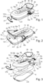
- the sled comprises an air mattress 1 having a lower wall 2 arranged to allow said sled to slide, an upper wall 3 arranged to allow at least one user to sit on it, and a peripheral wall 4 connecting said lower and upper walls.
- the lower 2 and upper 3 walls both extend in a horizontal plane, respectively lower and upper, the peripheral wall 4 extending in height between said planes.
- the air mattress 1 comprises an air bladder 5, a lower shell 6 carrying the lower wall 2 and an upper shell 7 carrying the upper wall 3, said shells being associated to form a peripheral wall 4 delimiting with said upper and lower walls a space 8 in which the bladder 5 is arranged.
- the shells 6, 7 may be made of a textile material, for example a synthetic fabric based on polyester and/or polyamide.
- the sled comprises a canvas 9 which covers the underside of the lower shell 6, said canvas forming the lower sliding wall 2 of said sled.
- the canvas 9 is made of a suitable material, for example oilcloth, and may also have a network of hollow and/or raised patterns arranged to facilitate its sliding on snowy terrain.
- the upper shell 7 has an orifice 11 in which a valve for inflating the bladder 5 is accessible, said orifice being formed on a rear peripheral edge of said upper shell.
- the orifice is equipped with a reversible closing device, for example in the form of a screw-on or push-on cap, in order to conceal access to the valve when it is not in use.
- a reversible closing device for example in the form of a screw-on or push-on cap, in order to conceal access to the valve when it is not in use.
- the upper wall 3 has a hollow imprint 13, in order to form a seating area to improve the comfort of the user(s) occupying the sled.
- the hollow impression 13 can extend over a significant portion of the upper seat wall 3, so as to allow an adult user to sit there by extending his legs over a front portion of said impression.
- the bladder 5 is formed from a tube of toric geometry in which a housing 14 is formed, said tube being in particular made of a polymer material, for example based on polyvinyl chloride (PVC) and/or thermoplastic polyurethane (TPU).
- PVC polyvinyl chloride
- TPU thermoplastic polyurethane
- the seat wall 3 extends above the housing 14, and may also have a longitudinal opening 15 which can be closed, in particular by means of a zipper type system.
- the user can thus access the housing 14 through this opening 15, in order to be able to store or extract material therein such as clothing items such as gloves and/or hats, to avoid their loss when they are not in use, or another portable manual inflation device, so that the sled can be re-inflated if necessary during use.
- material therein such as clothing items such as gloves and/or hats, to avoid their loss when they are not in use, or another portable manual inflation device, so that the sled can be re-inflated if necessary during use.
- the peripheral wall 4 of the sled extends over an edge of at least one shell 6, 7.
- the shells 6, 7 each have a peripheral border 6a, 7a, the air mattress 1 comprising a strip 16 for associating said borders to form the space 8 in which the bladder 5 is arranged.
- the housing 19 may also be formed in one piece by molding, thereby facilitating the manufacture of the braking system 17.
- This arrangement makes it easier to manufacture the sled, and in particular the air mattress 1. Furthermore, the arrangement of the braking system 17 on the periphery of the mattress 1 does not alter the lower wall 2, which improves the glide of the sled, and also allows the user to locate and operate it easily, in order to be able to control its movements in a simple and intuitive manner.
- Each fixing device comprises at least one strap 21 associated on the peripheral wall 4 to be engaged in the housing 19, said strap being tightenable on said peripheral wall in the fixing configuration and detachable from the housing 19 in the disassembly configuration.
- this embodiment makes it possible to press the housing 19 against the peripheral wall 4, which improves the stability of the system with respect to the braking forces to which it is subjected.
- each fixing device comprises two straps 21 which are spaced longitudinally on the peripheral wall 4, each of the straps 21 being engaged in the housing 19.
- the risks of pivoting of the braking system 17 during its actuation are limited, so as to optimize the braking force transmitted by the lever 18.
- the fixing member 24 is associated with one end of a strap 25, which is folded on itself to form a loop fixed by sewing in the downstream loop. of said organ, the other end of said strap being fixed by sewing on a patch 26 of the peripheral wall 4.
- the seat back 28 comprises two lateral straps 29, the respective free ends of which are each associated with a fastening member 30, for example a rigid buckle of the “double D” type, said members being fixed respectively to a patch 26 of the peripheral wall 4.
Landscapes
- Engineering & Computer Science (AREA)
- Chemical & Material Sciences (AREA)
- Combustion & Propulsion (AREA)
- Transportation (AREA)
- Mechanical Engineering (AREA)
- Mattresses And Other Support Structures For Chairs And Beds (AREA)
- Invalid Beds And Related Equipment (AREA)
Claims (15)
- Schlitten, umfassend eine Luftmatratze (1), die eine untere Wand (2), die angeordnet ist, um das Gleiten des Schlittens zu ermöglichen, eine obere Wand (3), die angeordnet ist, um das Sitzen mindestens eines Benutzers auf ihr zu ermöglichen, und eine Umfangswand (4) aufweist, die die untere und die obere Wand verbindet, wobei der Schlitten mit mindestens einem Bremssystem (17) ausgestattet ist, das einen Hebel (18) umfasst, der eine untere Kufe (18b) bildet, die von einem oberen Griff (18a) betätigt wird, wobei der Hebel in einem Gehäuse (19) zwischen einer inaktiven Position, in der die Kufe (18b) zum Gehäuse (19) hin zurückgezogen ist, und einer Bremsposition durch Ziehen am Griff (18a) drehbar montiert ist, um die Kufe von der unteren Wand (2) vorstehen zu lassen, wobei der Schlitten dadurch gekennzeichnet ist, dass die Umfangswand (4) mit einer Vorrichtung zur reversiblen Befestigung des Gehäuses (19) an ihr ausgestattet ist, wobei die Vorrichtung mindestens einen Gurt (21) umfasst, der mit dem Gehäuse (19) zwischen einer Konfiguration durch Klemmbefestigung des Gehäuses auf der Umfangswand und einer Konfiguration zum Abnehmen des Gehäuses abnehmbar verbunden ist.
- Schlitten nach Anspruch 1, dadurch gekennzeichnet, dass er zwei Bremssysteme (17) aufweist, deren Gehäuse (19) an einem linken bzw. rechten Abschnitt der Umfangswand (4) befestigt sind, wobei jeder der mittleren Abschnitte mit einer Vorrichtung (21) zur reversiblen Befestigung des Gehäuses (19) an ihnen ausgestattet sind.
- Schlitten nach einem der Ansprüche 1 oder 2, dadurch gekennzeichnet, dass der Gurt (21) mit der Umfangswand (4) verbunden ist, um in das Gehäuse (19) eingeführt zu sein, wobei der Gurt in der Konfiguration zur Klemmbefestigung an der Umfangswand festklemmbar und in der Konfiguration zum Abnehmen vom Gehäuse (19) lösbar ist.
- Schlitten nach Anspruch 3, dadurch gekennzeichnet, dass das Gehäuse (19) mindestens einen Schlitz (22a, 22b, 23a, 23b) aufweist, in den der Gurt (21 ) gleitend eingeführt ist.
- Schlitten nach einem der Ansprüche 3 oder 4, dadurch gekennzeichnet, dass der Gurt (21 ) ein Segment (21a), das dauerhaft auf einem ersten Teil (16) der Umfangswand (4) befestigt ist, ein Zwischensegment (21b), das in das Gehäuse (19) eingreift, und ein freies Segment (21c) aufweist, das angeordnet ist, um dazu zu kommen, reversibel in ein Befestigungsorgan (24) einzugreifen, das fest mit einem zweiten Teil der Umfangswand verbunden ist, wobei das Organ die Einstellung und die Längsfixierung des Gurtes ermöglicht, um seine Klemmbefestigung zu gewährleisten.
- Schlitten nach einem der Ansprüche 5, dadurch gekennzeichnet, dass das Befestigungsorgan (24) mit einem Ende eines Gurtes (25) verbunden ist, wobei das andere Ende des Gurtes an einem Patch (26) der Umfangswand (4) befestigt ist.
- Schlitten nach Anspruch 6, dadurch gekennzeichnet, dass er ein Organ (30) zum Einhängen eines Zubehörs (28) umfasst, wobei das Organ an dem Patch (26) der Umfangswand (4) befestigt ist.
- Schlitten nach einem der Ansprüche 1 bis 7, dadurch gekennzeichnet, dass die Vorrichtung zur Befestigung zwei Gurte (21) umfasst, die in Längsrichtung an der Umfangswand (4) im Abstand angeordnet sind.
- Schlitten nach einem der Ansprüche 1 bis 8, dadurch gekennzeichnet, dass die Luftmatratze (1) eine Luftblase (5), eine untere Schale (6), die die untere Wand (2) trägt, und eine obere Schale (7) umfasst, die die obere Wand (3) trägt, wobei die Schalen miteinander verbunden sind, indem sie eine Umfangswand (4) bilden, die mit der oberen (3) und unteren (2) Wand einen Raum (8) begrenzt, in dem die Blase (5) angeordnet ist.
- Schlitten nach Anspruch 9, dadurch gekennzeichnet, dass sich die Umfangswand (4) über einen Rand von mindestens einer Schale (6, 7) erstreckt.
- Schlitten nach einem der Ansprüche 9 oder 10, dadurch gekennzeichnet, dass die Schalen (6, 7) jeweils einen Umfangsrand (6a, 7a) aufweisen, wobei die Luftmatratze (1) eine Bandleiste (16) zum Verbinden der Ränder umfasst, um den Raum (8) zu bilden, in dem die Blase (5) angeordnet ist.
- Schlitten nach Anspruch 11, dadurch gekennzeichnet, dass der Gurt (21) ein Segment (21a) aufweist, das an der Bandleiste (16) befestigt ist.
- Schlitten nach einem der Ansprüche 9 bis 12, dadurch gekennzeichnet, dass er ein Geflecht (9) umfasst, das die Unterseite der unteren Schale (6) bedeckt, wobei das Geflecht die untere Wand (2) bildet, die angeordnet ist, um das Gleiten des Schlittens zu ermöglichen.
- Schlitten nach einem der Ansprüche 9 bis 13, dadurch gekennzeichnet, dass die Blase (5) aus einem Wulst mit torischer Geometrie gebildet ist, in dem eine Aufnahme (14) ausgebildet ist.
- Schlitten nach einem der Ansprüche 1 bis 14, dadurch gekennzeichnet, dass er mit mindestens einem Zubehörteil ausgestattet ist, das aus einem Zugseil (27) und einer Sitzlehne (28) ausgewählt ist.
Applications Claiming Priority (1)
| Application Number | Priority Date | Filing Date | Title |
|---|---|---|---|
| FR2207206A FR3137891B1 (fr) | 2022-07-13 | 2022-07-13 | Luge gonflable |
Publications (3)
| Publication Number | Publication Date |
|---|---|
| EP4306386A1 EP4306386A1 (de) | 2024-01-17 |
| EP4306386C0 EP4306386C0 (de) | 2025-04-23 |
| EP4306386B1 true EP4306386B1 (de) | 2025-04-23 |
Family
ID=84369798
Family Applications (1)
| Application Number | Title | Priority Date | Filing Date |
|---|---|---|---|
| EP23184494.5A Active EP4306386B1 (de) | 2022-07-13 | 2023-07-10 | Aufblasbarer schlitten |
Country Status (3)
| Country | Link |
|---|---|
| EP (1) | EP4306386B1 (de) |
| CN (1) | CN117401020A (de) |
| FR (1) | FR3137891B1 (de) |
Family Cites Families (3)
| Publication number | Priority date | Publication date | Assignee | Title |
|---|---|---|---|---|
| US20030020248A1 (en) * | 2001-07-25 | 2003-01-30 | Oberpriller Barry G. | Inflatable tube ski vehicle with steering mechanism |
| US6637552B1 (en) | 2002-09-26 | 2003-10-28 | Sportsstuff, Inc. | Inflatable vehicle braking system |
| DE20215554U1 (de) * | 2002-10-09 | 2004-02-19 | Millennium 2000 Gmbh Hegener & Weiner | Aufblasbares Gleitfahrzeug |
-
2022
- 2022-07-13 FR FR2207206A patent/FR3137891B1/fr active Active
-
2023
- 2023-07-10 EP EP23184494.5A patent/EP4306386B1/de active Active
- 2023-07-13 CN CN202310862278.9A patent/CN117401020A/zh active Pending
Also Published As
| Publication number | Publication date |
|---|---|
| EP4306386A1 (de) | 2024-01-17 |
| CN117401020A (zh) | 2024-01-16 |
| FR3137891A1 (fr) | 2024-01-19 |
| EP4306386C0 (de) | 2025-04-23 |
| FR3137891B1 (fr) | 2024-07-19 |
Similar Documents
| Publication | Publication Date | Title |
|---|---|---|
| CN106573636B (zh) | 儿童车 | |
| US7401803B1 (en) | Stroller | |
| FR3050712A1 (de) | ||
| CA2825870A1 (fr) | Fauteuil pliant | |
| FR2548106A1 (fr) | Siege auxiliaire pour vehicules | |
| EP4306386B1 (de) | Aufblasbarer schlitten | |
| EP3984859B1 (de) | Modularer schlitten | |
| JP7223485B2 (ja) | 座の構造、及び椅子 | |
| FR2565085A1 (fr) | Dispositif a accotoir reglable en hauteur pour siege, et siege equipe de tels accotoirs | |
| FR2922733A1 (fr) | Contenant a roulettes, notamment valise | |
| FR2776169A1 (fr) | Article de portage a bretelles et a roulettes | |
| EP0516512A1 (de) | Rücksitzbank für Kraftfahrzeuge | |
| CN205381293U (zh) | 婴儿车防夹手展开收合装置 | |
| FR2871117A1 (fr) | Siege de vehicule a rehausseur integre | |
| EP2246217B1 (de) | Vorrichtung zum Verstauen einer Sicherheitsweste in der Kopfstütze einer Fahrzeugsitzrückenlehne | |
| EP2911550A1 (de) | Als schultertasche oder rucksack tragbarer beutel | |
| WO2019162631A1 (fr) | Bagage à coques rabattables l'une contre l'autre | |
| CH690497A5 (fr) | Article de glisse pour le sport et le loisir sur une surface neigeuse. | |
| FR2931422A1 (fr) | Siege de vehicule automobile | |
| FR2884772A1 (fr) | Coussin amovible pour siege de vehicule automobile, ensemble de siege comprenant un tel coussin, et vehicule automobile correspondants. | |
| KR200426868Y1 (ko) | 유아용 좌석이 부착된 여행용 가방 | |
| CA3036606C (fr) | Accessoire pour poussette, ainsi qu'ensemble de transport comprenant une poussette et un tel accessoire | |
| FR3126372A1 (fr) | Siège de véhicule doté d’un système de sécurité embarqué. | |
| FR2907066A1 (fr) | Repose-pieds pour passager arriere d'un vehicule automobile, et siege correspondant. | |
| WO2023021253A1 (fr) | Structure d'accueil convertible pour poussette pliable |
Legal Events
| Date | Code | Title | Description |
|---|---|---|---|
| PUAI | Public reference made under article 153(3) epc to a published international application that has entered the european phase |
Free format text: ORIGINAL CODE: 0009012 |
|
| STAA | Information on the status of an ep patent application or granted ep patent |
Free format text: STATUS: THE APPLICATION HAS BEEN PUBLISHED |
|
| AK | Designated contracting states |
Kind code of ref document: A1 Designated state(s): AL AT BE BG CH CY CZ DE DK EE ES FI FR GB GR HR HU IE IS IT LI LT LU LV MC ME MK MT NL NO PL PT RO RS SE SI SK SM TR |
|
| STAA | Information on the status of an ep patent application or granted ep patent |
Free format text: STATUS: REQUEST FOR EXAMINATION WAS MADE |
|
| 17P | Request for examination filed |
Effective date: 20240715 |
|
| RBV | Designated contracting states (corrected) |
Designated state(s): AL AT BE BG CH CY CZ DE DK EE ES FI FR GB GR HR HU IE IS IT LI LT LU LV MC ME MK MT NL NO PL PT RO RS SE SI SK SM TR |
|
| GRAP | Despatch of communication of intention to grant a patent |
Free format text: ORIGINAL CODE: EPIDOSNIGR1 |
|
| STAA | Information on the status of an ep patent application or granted ep patent |
Free format text: STATUS: GRANT OF PATENT IS INTENDED |
|
| INTG | Intention to grant announced |
Effective date: 20241119 |
|
| GRAS | Grant fee paid |
Free format text: ORIGINAL CODE: EPIDOSNIGR3 |
|
| GRAA | (expected) grant |
Free format text: ORIGINAL CODE: 0009210 |
|
| STAA | Information on the status of an ep patent application or granted ep patent |
Free format text: STATUS: THE PATENT HAS BEEN GRANTED |
|
| AK | Designated contracting states |
Kind code of ref document: B1 Designated state(s): AL AT BE BG CH CY CZ DE DK EE ES FI FR GB GR HR HU IE IS IT LI LT LU LV MC ME MK MT NL NO PL PT RO RS SE SI SK SM TR |
|
| REG | Reference to a national code |
Ref country code: GB Ref legal event code: FG4D Free format text: NOT ENGLISH |
|
| REG | Reference to a national code |
Ref country code: CH Ref legal event code: EP |
|
| REG | Reference to a national code |
Ref country code: DE Ref legal event code: R096 Ref document number: 602023003046 Country of ref document: DE |
|
| REG | Reference to a national code |
Ref country code: IE Ref legal event code: FG4D Free format text: LANGUAGE OF EP DOCUMENT: FRENCH |
|
| U01 | Request for unitary effect filed |
Effective date: 20250522 |
|
| U07 | Unitary effect registered |
Designated state(s): AT BE BG DE DK EE FI FR IT LT LU LV MT NL PT RO SE SI Effective date: 20250701 |
|
| U20 | Renewal fee for the european patent with unitary effect paid |
Year of fee payment: 3 Effective date: 20250728 |
|
| PG25 | Lapsed in a contracting state [announced via postgrant information from national office to epo] |
Ref country code: ES Free format text: LAPSE BECAUSE OF FAILURE TO SUBMIT A TRANSLATION OF THE DESCRIPTION OR TO PAY THE FEE WITHIN THE PRESCRIBED TIME-LIMIT Effective date: 20250423 |
|
| PG25 | Lapsed in a contracting state [announced via postgrant information from national office to epo] |
Ref country code: NO Free format text: LAPSE BECAUSE OF FAILURE TO SUBMIT A TRANSLATION OF THE DESCRIPTION OR TO PAY THE FEE WITHIN THE PRESCRIBED TIME-LIMIT Effective date: 20250723 Ref country code: GR Free format text: LAPSE BECAUSE OF FAILURE TO SUBMIT A TRANSLATION OF THE DESCRIPTION OR TO PAY THE FEE WITHIN THE PRESCRIBED TIME-LIMIT Effective date: 20250724 |
|
| PG25 | Lapsed in a contracting state [announced via postgrant information from national office to epo] |
Ref country code: PL Free format text: LAPSE BECAUSE OF FAILURE TO SUBMIT A TRANSLATION OF THE DESCRIPTION OR TO PAY THE FEE WITHIN THE PRESCRIBED TIME-LIMIT Effective date: 20250423 |
|
| PG25 | Lapsed in a contracting state [announced via postgrant information from national office to epo] |
Ref country code: HR Free format text: LAPSE BECAUSE OF FAILURE TO SUBMIT A TRANSLATION OF THE DESCRIPTION OR TO PAY THE FEE WITHIN THE PRESCRIBED TIME-LIMIT Effective date: 20250423 |
|
| PG25 | Lapsed in a contracting state [announced via postgrant information from national office to epo] |
Ref country code: RS Free format text: LAPSE BECAUSE OF FAILURE TO SUBMIT A TRANSLATION OF THE DESCRIPTION OR TO PAY THE FEE WITHIN THE PRESCRIBED TIME-LIMIT Effective date: 20250723 |
|
| PG25 | Lapsed in a contracting state [announced via postgrant information from national office to epo] |
Ref country code: IS Free format text: LAPSE BECAUSE OF FAILURE TO SUBMIT A TRANSLATION OF THE DESCRIPTION OR TO PAY THE FEE WITHIN THE PRESCRIBED TIME-LIMIT Effective date: 20250823 |
|
| PG25 | Lapsed in a contracting state [announced via postgrant information from national office to epo] |
Ref country code: SM Free format text: LAPSE BECAUSE OF FAILURE TO SUBMIT A TRANSLATION OF THE DESCRIPTION OR TO PAY THE FEE WITHIN THE PRESCRIBED TIME-LIMIT Effective date: 20250423 |
|
| PG25 | Lapsed in a contracting state [announced via postgrant information from national office to epo] |
Ref country code: CZ Free format text: LAPSE BECAUSE OF FAILURE TO SUBMIT A TRANSLATION OF THE DESCRIPTION OR TO PAY THE FEE WITHIN THE PRESCRIBED TIME-LIMIT Effective date: 20250423 |
|
| PG25 | Lapsed in a contracting state [announced via postgrant information from national office to epo] |
Ref country code: SK Free format text: LAPSE BECAUSE OF FAILURE TO SUBMIT A TRANSLATION OF THE DESCRIPTION OR TO PAY THE FEE WITHIN THE PRESCRIBED TIME-LIMIT Effective date: 20250423 |