EP4303984A1 - Energiespeichersystem, batterieüberwachungsverfahren und energiespeichervorrichtung - Google Patents
Energiespeichersystem, batterieüberwachungsverfahren und energiespeichervorrichtung Download PDFInfo
- Publication number
- EP4303984A1 EP4303984A1 EP21932098.3A EP21932098A EP4303984A1 EP 4303984 A1 EP4303984 A1 EP 4303984A1 EP 21932098 A EP21932098 A EP 21932098A EP 4303984 A1 EP4303984 A1 EP 4303984A1
- Authority
- EP
- European Patent Office
- Prior art keywords
- battery
- temperature
- temperature signal
- area
- monitoring unit
- Prior art date
- Legal status (The legal status is an assumption and is not a legal conclusion. Google has not performed a legal analysis and makes no representation as to the accuracy of the status listed.)
- Pending
Links
Images

Classifications
-
- H—ELECTRICITY
- H01—ELECTRIC ELEMENTS
- H01M—PROCESSES OR MEANS, e.g. BATTERIES, FOR THE DIRECT CONVERSION OF CHEMICAL ENERGY INTO ELECTRICAL ENERGY
- H01M10/00—Secondary cells; Manufacture thereof
- H01M10/60—Heating or cooling; Temperature control
- H01M10/61—Types of temperature control
- H01M10/617—Types of temperature control for achieving uniformity or desired distribution of temperature
-
- H—ELECTRICITY
- H01—ELECTRIC ELEMENTS
- H01M—PROCESSES OR MEANS, e.g. BATTERIES, FOR THE DIRECT CONVERSION OF CHEMICAL ENERGY INTO ELECTRICAL ENERGY
- H01M10/00—Secondary cells; Manufacture thereof
- H01M10/42—Methods or arrangements for servicing or maintenance of secondary cells or secondary half-cells
- H01M10/425—Structural combination with electronic components, e.g. electronic circuits integrated to the outside of the casing
-
- H—ELECTRICITY
- H01—ELECTRIC ELEMENTS
- H01M—PROCESSES OR MEANS, e.g. BATTERIES, FOR THE DIRECT CONVERSION OF CHEMICAL ENERGY INTO ELECTRICAL ENERGY
- H01M10/00—Secondary cells; Manufacture thereof
- H01M10/42—Methods or arrangements for servicing or maintenance of secondary cells or secondary half-cells
- H01M10/4285—Testing apparatus
-
- H—ELECTRICITY
- H01—ELECTRIC ELEMENTS
- H01M—PROCESSES OR MEANS, e.g. BATTERIES, FOR THE DIRECT CONVERSION OF CHEMICAL ENERGY INTO ELECTRICAL ENERGY
- H01M10/00—Secondary cells; Manufacture thereof
- H01M10/42—Methods or arrangements for servicing or maintenance of secondary cells or secondary half-cells
- H01M10/48—Accumulators combined with arrangements for measuring, testing or indicating the condition of cells, e.g. the level or density of the electrolyte
- H01M10/482—Accumulators combined with arrangements for measuring, testing or indicating the condition of cells, e.g. the level or density of the electrolyte for several batteries or cells simultaneously or sequentially
-
- H—ELECTRICITY
- H01—ELECTRIC ELEMENTS
- H01M—PROCESSES OR MEANS, e.g. BATTERIES, FOR THE DIRECT CONVERSION OF CHEMICAL ENERGY INTO ELECTRICAL ENERGY
- H01M10/00—Secondary cells; Manufacture thereof
- H01M10/42—Methods or arrangements for servicing or maintenance of secondary cells or secondary half-cells
- H01M10/48—Accumulators combined with arrangements for measuring, testing or indicating the condition of cells, e.g. the level or density of the electrolyte
- H01M10/486—Accumulators combined with arrangements for measuring, testing or indicating the condition of cells, e.g. the level or density of the electrolyte for measuring temperature
-
- H—ELECTRICITY
- H01—ELECTRIC ELEMENTS
- H01M—PROCESSES OR MEANS, e.g. BATTERIES, FOR THE DIRECT CONVERSION OF CHEMICAL ENERGY INTO ELECTRICAL ENERGY
- H01M10/00—Secondary cells; Manufacture thereof
- H01M10/60—Heating or cooling; Temperature control
- H01M10/65—Means for temperature control structurally associated with the cells
- H01M10/651—Means for temperature control structurally associated with the cells characterised by parameters specified by a numeric value or mathematical formula, e.g. ratios, sizes or concentrations
- H01M10/652—Means for temperature control structurally associated with the cells characterised by parameters specified by a numeric value or mathematical formula, e.g. ratios, sizes or concentrations characterised by gradients
-
- H—ELECTRICITY
- H01—ELECTRIC ELEMENTS
- H01M—PROCESSES OR MEANS, e.g. BATTERIES, FOR THE DIRECT CONVERSION OF CHEMICAL ENERGY INTO ELECTRICAL ENERGY
- H01M10/00—Secondary cells; Manufacture thereof
- H01M10/42—Methods or arrangements for servicing or maintenance of secondary cells or secondary half-cells
- H01M10/425—Structural combination with electronic components, e.g. electronic circuits integrated to the outside of the casing
- H01M2010/4271—Battery management systems including electronic circuits, e.g. control of current or voltage to keep battery in healthy state, cell balancing
-
- H—ELECTRICITY
- H01—ELECTRIC ELEMENTS
- H01M—PROCESSES OR MEANS, e.g. BATTERIES, FOR THE DIRECT CONVERSION OF CHEMICAL ENERGY INTO ELECTRICAL ENERGY
- H01M10/00—Secondary cells; Manufacture thereof
- H01M10/42—Methods or arrangements for servicing or maintenance of secondary cells or secondary half-cells
- H01M10/425—Structural combination with electronic components, e.g. electronic circuits integrated to the outside of the casing
- H01M2010/4278—Systems for data transfer from batteries, e.g. transfer of battery parameters to a controller, data transferred between battery controller and main controller
-
- H—ELECTRICITY
- H01—ELECTRIC ELEMENTS
- H01M—PROCESSES OR MEANS, e.g. BATTERIES, FOR THE DIRECT CONVERSION OF CHEMICAL ENERGY INTO ELECTRICAL ENERGY
- H01M2200/00—Safety devices for primary or secondary batteries
- H01M2200/10—Temperature sensitive devices
- H01M2200/105—NTC
-
- H—ELECTRICITY
- H01—ELECTRIC ELEMENTS
- H01M—PROCESSES OR MEANS, e.g. BATTERIES, FOR THE DIRECT CONVERSION OF CHEMICAL ENERGY INTO ELECTRICAL ENERGY
- H01M50/00—Constructional details or processes of manufacture of the non-active parts of electrochemical cells other than fuel cells, e.g. hybrid cells
- H01M50/20—Mountings; Secondary casings or frames; Racks, modules or packs; Suspension devices; Shock absorbers; Transport or carrying devices; Holders
- H01M50/204—Racks, modules or packs for multiple batteries or multiple cells
-
- H—ELECTRICITY
- H01—ELECTRIC ELEMENTS
- H01M—PROCESSES OR MEANS, e.g. BATTERIES, FOR THE DIRECT CONVERSION OF CHEMICAL ENERGY INTO ELECTRICAL ENERGY
- H01M50/00—Constructional details or processes of manufacture of the non-active parts of electrochemical cells other than fuel cells, e.g. hybrid cells
- H01M50/50—Current conducting connections for cells or batteries
- H01M50/572—Means for preventing undesired use or discharge
- H01M50/574—Devices or arrangements for the interruption of current
- H01M50/581—Devices or arrangements for the interruption of current in response to temperature
-
- Y—GENERAL TAGGING OF NEW TECHNOLOGICAL DEVELOPMENTS; GENERAL TAGGING OF CROSS-SECTIONAL TECHNOLOGIES SPANNING OVER SEVERAL SECTIONS OF THE IPC; TECHNICAL SUBJECTS COVERED BY FORMER USPC CROSS-REFERENCE ART COLLECTIONS [XRACs] AND DIGESTS
- Y02—TECHNOLOGIES OR APPLICATIONS FOR MITIGATION OR ADAPTATION AGAINST CLIMATE CHANGE
- Y02E—REDUCTION OF GREENHOUSE GAS [GHG] EMISSIONS, RELATED TO ENERGY GENERATION, TRANSMISSION OR DISTRIBUTION
- Y02E60/00—Enabling technologies; Technologies with a potential or indirect contribution to GHG emissions mitigation
- Y02E60/10—Energy storage using batteries
Definitions
- This application relates to the field of battery technologies, and in particular, to an energy storage system, a battery monitoring method, and an energy storage device.
- Energy storage systems are applied in a wide range of scenarios, such as power generation, power transmission, power transformation, power distribution, and power consumption of a power system.
- a temperature of a cell of a battery module in the energy storage system directly affects charge and discharge efficiency of the energy storage system. Thermal runaway may cause a rapid decrease in a capacity and a service life of the cell, and even cause an explosion. This affects reliability and economical performance of the energy storage system.
- each battery management system (battery management system, BMS) has a plurality of negative temperature coefficient (negative temperature coefficient, NTC) temperature sensors.
- the NTC temperature sensor detects a temperature of a cell in real time, and transmits the detected temperature to a battery monitoring unit (battery monitoring unit, BMU).
- BMU battery monitoring unit
- the BMU determines thermal runaway. When the received temperature signal reaches a preset thermal runaway temperature threshold, the BMU controls derating or shutdown of a current battery module.
- controlling the current battery module by the BMU depends on precision and reliability of the NTC temperature sensor. As a result, the BMU is prone to protecting the battery module incorrectly.
- This application provides an energy storage system, a battery monitoring method, and an energy storage device, to improve precision and stability of the energy storage system.
- a first aspect of this application provides an energy storage system.
- the energy storage system includes a battery monitoring unit, a battery module, and a temperature sensor.
- the battery module includes at least two battery areas, the temperature sensor is disposed in each battery area, and each battery area includes at least one battery.
- the battery monitoring unit is configured to: receive a plurality of temperature signals, where each of the plurality of temperature signals comes from temperature sensors in different battery areas; when there is an abnormal temperature signal that reaches a first preset temperature threshold in the plurality of temperature signals, obtain a plurality of adjacent temperature signals, where the adjacent temperature signal is a temperature signal corresponding to a second battery area that is connected to a first battery area corresponding to the abnormal temperature signal, and there are one or more second battery areas; and when the adjacent temperature signal is greater than a second preset temperature threshold, reduce rated power of the battery module.
- batteries in the battery module are divided into a plurality of battery areas, and one temperature sensor is disposed in each battery area.
- the temperature sensor monitors a temperature signal of each battery area in real time, and sends the plurality of temperature signals to the battery monitoring unit.
- the battery monitoring unit may determine that there is a possibility of thermal runaway in the first battery area corresponding to the abnormal temperature signal. Then, the battery monitoring unit may obtain, from the plurality of temperature signals, the adjacent temperature signal of the second battery area that is connected to the first battery area. There may be one or more second battery areas.
- the battery monitoring unit may determine, based on a characteristic of thermal diffusion, that thermal runaway actually occurs in the first battery area, and therefore may reduce the rated power of the battery module. In this way, multi-dimensional monitoring is implemented, false reporting of the temperature signal is avoided, and the battery module is not abnormally derated or shut down because a specific temperature sensor is faulty. This improves precision and stability of the energy storage system.
- the battery monitoring unit is configured to: when the adjacent temperature signal is less than the second preset temperature threshold, report fault information, where the fault information indicates that a temperature sensor corresponding to the abnormal temperature signal is faulty.
- the battery monitoring unit may determine that an actual temperature of the first battery area does not reach the first preset temperature threshold, and the abnormal temperature signal is an incorrect temperature signal, in other words, the temperature sensor in the first battery area is faulty.
- the battery monitoring unit may report the fault information indicating that the temperature sensor is faulty, to replace the faulty temperature sensor in time. This improves precision of the energy storage system.
- the battery monitoring unit is configured to determine the first battery area corresponding to the abnormal temperature signal, determine the second battery area that is connected to the first battery area, and obtain the adjacent temperature signal based on a temperature sensor corresponding to the second battery area.
- the battery monitoring unit may determine the temperature sensor that sends the abnormal temperature signal, correspondingly determine the first battery area in which the temperature sensor is located, and determine, based on distribution of the battery areas in the battery module, the second battery area that is connected to the first battery area. Then, the battery monitoring unit may determine, from the temperature signals sent by the temperature sensor, one or more adjacent temperature signals corresponding to one or more second battery areas.
- the battery monitoring unit is configured to: when there is still a temperature signal that reaches the first preset temperature threshold in the plurality of temperature signals of the battery module whose rated power is reduced, shut down the battery module whose rated power is reduced.
- a battery area monitoring unit may directly shut down the battery module in addition to reducing the rated power of the battery module.
- the battery area monitoring unit may shut down the battery module if thermal runaway still occurs in one timer after the rated power of the battery module is reduced, to avoid damage to the battery module.
- the second preset temperature threshold is obtained by performing simulation by the battery monitoring unit based on the abnormal temperature signal.
- the battery monitoring unit may perform simulation on the abnormal temperature signal based on temperature diffusion, and determine, from a simulation result based on relative positions of the second battery area and the first battery area, the second preset temperature threshold after there is an abnormal temperature increment in the second battery area.
- a temperature field model is disposed in the battery area.
- the temperature field model is used for simulation based on the abnormal temperature signal to obtain the second preset temperature threshold.
- the temperature field model is a simulation model including temperature gradients that are formed based on temperature diffusion. The temperature gradients are gradients distinguished by temperatures.
- the battery monitoring unit may establish one temperature field model based on the temperature diffusion.
- the temperature field model is a simulation model including temperature gradients, and may reflect temperatures of different areas.
- a diffusion temperature of the second battery area in a thermal runaway state may be output.
- the diffusion temperature is the second preset temperature threshold.
- the temperature field model may further determine one abnormal increment based on the diffusion temperature and a temperature of the second battery area in a normal case. When a difference between the adjacent temperature signal and the temperature in the normal case is greater than the abnormal increment, the battery monitoring unit may reduce the rated power of the battery module or shut down the battery module.
- the plurality of battery areas are equally sized areas.
- the battery areas in the battery module are equally sized areas. This may facilitate the setting of the second preset temperature threshold based on temperature diffusion.
- a second aspect of this application provides a battery monitoring method.
- the method includes: A battery monitoring unit receives a plurality of temperature signals. Each of the plurality of temperature signals comes from temperature sensors in different battery areas. The battery area is disposed in a battery module. Each battery area includes at least one battery.
- the battery monitoring unit obtains a plurality of adjacent temperature signals.
- the adjacent temperature signal is a temperature signal corresponding to a second battery area that is connected to a first battery area corresponding to the abnormal temperature signal. There are one or more second battery areas. When the adjacent temperature signal is greater than a second preset temperature threshold, the battery monitoring unit reduces rated power of the battery module.
- the method further includes: When the adjacent temperature signal is less than the second preset temperature threshold, the battery monitoring unit reports fault information.
- the fault information indicates that a temperature sensor corresponding to the abnormal temperature signal is faulty.
- that the battery monitoring unit obtains a plurality of adjacent temperature signals in the foregoing steps includes: The battery monitoring unit determines the first battery area corresponding to the abnormal temperature signal. The battery monitoring unit determines the second battery area that is connected to the first battery area. The battery monitoring unit obtains the adjacent temperature signal based on a temperature sensor corresponding to the second battery area.
- the method further includes: when there is still a temperature signal that reaches the first preset temperature threshold in the plurality of temperature signals of the battery module whose rated power is reduced, shutting down the battery module whose rated power is reduced.
- the second preset temperature threshold is obtained by performing simulation by the battery monitoring unit based on the abnormal temperature signal.
- a temperature field model is disposed in the battery area.
- the temperature field model is used for simulation based on the abnormal temperature signal to obtain the second preset temperature threshold.
- the temperature field model is a simulation model including temperature gradients that are formed based on temperature diffusion. The temperature gradients are gradients distinguished by temperatures.
- the plurality of battery areas are equally sized areas.
- a third aspect of this application provides an energy storage device, including the following units.
- a receiving unit is configured to receive a plurality of temperature signals. Each of the plurality of temperature signals comes from temperature sensors in different battery areas. The battery area is disposed in a battery module. Each battery area includes at least one battery.
- An obtaining unit is configured to: when there is an abnormal temperature signal that reaches a first preset temperature threshold in the plurality of temperature signals, obtain a plurality of adjacent temperature signals.
- the adjacent temperature signal is a temperature signal corresponding to a second battery area that is connected to a first battery area corresponding to the abnormal temperature signal. There are one or more second battery areas.
- a derating unit is configured to: when the adjacent temperature signal is greater than a second preset temperature threshold, reduce rated power of the battery module.
- a fourth aspect of this application provides a computer device, including: a processor, a memory, and a communication interface.
- the processor is configured to execute instructions stored in the memory, to enable the computer device to perform the method according to any one of the second aspect or the optional implementations of the second aspect.
- the communication interface is configured to receive or send an indication.
- a fifth aspect of this application provides a computer-readable storage medium.
- the computer-readable storage medium stores a program.
- a computer executes the program, the method according to any one of the second aspect or the optional implementations of the second aspect is performed.
- a sixth aspect of this application provides a computer program product.
- the computer program product When the computer program product is executed on a computer, the computer is enabled to perform the method according to any one of the second aspect or the optional implementations of the second aspect.
- This application provides an energy storage system, a battery monitoring method, and an energy storage device, to improve precision and stability of the energy storage system.
- a battery management system (battery management system, BMS) is a system for managing a battery and usually has a function of measuring a battery voltage, to prevent or avoid an abnormal condition such as over-discharge, overcharge, and over-temperature of the battery. This can prolong a service life of the battery and monitor a battery status.
- FIG. 1 is a schematic diagram of an architecture of a battery management system according to an embodiment of this application.
- the architecture includes a BMS 1, a battery monitoring unit (battery monitoring unit, BMU) 11, and a battery module 12.
- the battery module 12 is a modular battery module assembled by highly consistent cells that are strictly screened and assembled based on precision design.
- a negative temperature coefficient (negative temperature coefficient, NTC) temperature sensor 121 is further disposed in the battery module 12.
- the NTC temperature sensor 121 may monitor a temperature of the battery module 12.
- the battery monitoring unit 11 may receive a temperature signal detected by the NTC temperature sensor 121, and then adjust use of the battery module based on the temperature signal, to avoid overheating of the battery module.
- Each BMS usually has a plurality of NTC temperature sensors.
- the NTC temperature sensor detects a temperature of a cell in real time, and transmits the detected temperature to the BMU. After receiving a temperature signal, the BMU determines thermal runaway. When the received temperature signal reaches a preset temperature threshold, the BMU controls derating or shutdown of a current battery module or battery cluster.
- accuracy of temperature detection is closely related to reliability of the NTC temperature sensor.
- a temperature detected by the NTC temperature sensor deviates, and a temperature signal fed back to the BMU deviates greatly from actual signal data. As a result, the rated power of the battery cluster is incorrectly reduced or the battery cluster is incorrectly shut down, affecting economical performance of the battery management system.
- the energy storage system includes a battery monitoring unit 11, a battery module 12, and a temperature sensor 121.
- the battery module 12 includes at least two battery areas 122.
- the temperature sensor 121 is disposed in each battery area 122.
- Each battery area 122 includes at least one battery (not shown in the figure).
- the battery monitoring unit 11 is configured to: receive a plurality of temperature signals, where each of the plurality of temperature signals comes from temperature sensors 121 in different battery areas 122; when there is an abnormal temperature signal that reaches a first preset temperature threshold in the plurality of temperature signals, obtain a plurality of adjacent temperature signals, where the adjacent temperature signal is a temperature signal corresponding to a second battery area 124 that is connected to a first battery area 123 corresponding to the abnormal temperature signal, and there are one or more second battery areas 124; and when the adjacent temperature signal is greater than a second preset temperature threshold, reduce rated power of the battery module 12.
- batteries in the battery module 12 are divided into a plurality of battery areas 122, and one temperature sensor 121 is disposed in each battery area 122.
- the temperature sensor 121 monitors a temperature signal of each battery area 122 in real time, and sends a plurality of temperature signals to the battery monitoring unit 11.
- the battery monitoring unit 11 may determine that there is a possibility of thermal runaway in the first battery area 123 corresponding to the abnormal temperature signal. Then, the battery monitoring unit 11 may obtain, from the plurality of temperature signals, the adjacent temperature signal of the second battery area 124 that is connected to the first battery area 123.
- the battery monitoring unit 11 may determine, based on a characteristic of thermal diffusion, that thermal runaway actually occurs in the first battery area 123, and therefore may reduce the rated power of the battery module 12. In this way, multi-dimensional monitoring is implemented, false reporting of the temperature signal is avoided, and the battery module is not abnormally derated or shut down because a specific temperature sensor is faulty. This improves precision and stability of the energy storage system.
- the battery monitoring unit 11 is configured to: when the adjacent temperature signal is less than the second preset temperature threshold, report fault information, where the fault information indicates that the temperature sensor 121 corresponding to the abnormal temperature signal is faulty.
- the battery monitoring unit 11 may determine that an actual temperature of the first battery area 123 does not reach the first preset temperature threshold, and the abnormal temperature signal is an incorrect temperature signal, in other words, the temperature sensor 121 in the first battery area 123 is faulty.
- the battery monitoring unit 11 may report the fault information indicating that the temperature sensor 121 is faulty, to replace the faulty temperature sensor 121 in time, and improve precision of the energy storage system.
- the battery monitoring unit 11 is configured to determine the first battery area 123 corresponding to the abnormal temperature signal, determine the second battery area 124 that is connected to the first battery area 123, and obtain the adjacent temperature signal based on the temperature sensor 121 corresponding to the second battery area 124.
- the battery monitoring unit 11 may determine the temperature sensor 121 that sends the abnormal temperature signal, correspondingly determine the first battery area 123 in which the temperature sensor 121 is located, and determine, based on distribution of the battery areas 122 in the battery module 12, the second battery area 124 that is connected to the first battery area 123. Then, the battery monitoring unit 11 may determine, from the temperature signal sent by the temperature sensor 121, one or more adjacent temperature signals corresponding to one or more second battery areas 124.
- the battery monitoring unit 11 is configured to: when there is still a temperature signal that reaches the first preset temperature threshold in the plurality of temperature signals of the battery module 12 whose rated power is reduced, shut down the battery module 12 whose rated power is reduced.
- a battery area 122 monitoring unit may directly shut down the battery module 12 in addition to reducing the rated power of the battery module 12.
- the battery area 122 monitoring unit may shut down the battery module if thermal runaway still occurs in one timer after the rated power of the battery module 12 is reduced, to avoid damage to the battery module.
- the second preset temperature threshold is obtained by performing simulation by the battery monitoring unit 11 based on the abnormal temperature signal.
- the battery monitoring unit 11 may perform simulation on the abnormal temperature signal based on temperature diffusion, and determine, from a simulation result based on relative positions of the second battery area 124 and the first battery area 123, the second preset temperature threshold after there is an abnormal temperature increment in the second battery area 124.
- a temperature field model is disposed in the battery area 122.
- the temperature field model is used for simulation based on the abnormal temperature signal to obtain the second preset temperature threshold.
- the temperature field model is a simulation model including temperature gradients that are formed based on the temperature diffusion. The temperature gradients are gradients distinguished by temperatures.
- the battery monitoring unit 11 may establish one temperature field model based on the temperature diffusion.
- the temperature field model is a simulation model including temperature gradients.
- the temperature field model may reflect temperatures of different areas.
- a diffusion temperature of the second battery area 124 in a thermal runaway state may be output.
- the diffusion temperature is the second preset temperature threshold.
- the temperature field model may further determine one abnormal increment based on the diffusion temperature and a temperature of the second battery area 124 in a normal case. When a difference between the adjacent temperature signal and the temperature in the normal case is greater than the abnormal increment, the battery monitoring unit 11 may reduce the rated power of the battery module 12 or shut down the battery module 12.
- the plurality of battery areas 122 are equally sized areas.
- the battery areas 122 in the battery module 12 are equally sized areas. This may facilitate the setting of the second preset temperature threshold based on the temperature diffusion.
- a battery monitoring unit receives a plurality of temperature signals.
- batteries in a battery module are divided into a plurality of battery areas, and one temperature sensor is disposed in each battery area.
- the temperature sensor monitors a temperature signal of each battery area in real time, and sends a plurality of temperature signals corresponding to the plurality of battery areas to the battery monitoring unit.
- the battery monitoring unit may receive the plurality of temperature signals.
- the plurality of battery areas are equally sized areas.
- the battery areas in the battery module are equally sized areas. This may facilitate setting of a monitoring range of the temperature sensor, and facilitate subsequent setting of a second preset temperature threshold based on temperature diffusion.
- the battery monitoring unit obtains a plurality of adjacent temperature signals.
- the battery monitoring unit may determine a relationship between the plurality of temperature signals and the first preset temperature threshold.
- the first preset temperature threshold is preconfigured or updated in real time.
- the battery monitoring unit may determine that there is a possibility of thermal runaway in a first battery area in which the temperature sensor sending the abnormal temperature signal is located. The thermal runaway indicates that the first battery area may be damaged due to an excessively high temperature, and the battery module needs to be derated or shut down in time.
- the battery monitoring unit may further obtain one or more adj acent temperature signals of one or more second battery areas that are connected to the first battery area.
- the battery monitoring unit determines the first battery area corresponding to the abnormal temperature signal.
- the battery monitoring unit determines the second battery area that is connected to the first battery area.
- the battery monitoring unit obtains the adjacent temperature signal based on a temperature sensor corresponding to the second battery area.
- the battery monitoring unit after detecting the abnormal temperature signal, needs to determine the first battery area that generates the abnormal temperature signal, and then determines the adjacent temperature signal of the second battery area from the plurality of temperature signals, to subsequently perform corresponding detection on the adjacent temperature signal.
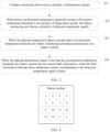
- the battery module is divided into battery areas 1, 2, ..., and n.
- the temperature sensor in each battery area transmits a temperature to the battery monitoring unit.
- the battery monitoring unit may locate the first battery area corresponding to the abnormal temperature signal, for example, "6" in FIG. 4 , in other words, corresponding second battery areas are ⁇ 1, 2, 3, 5, 7, 9, 10, 11 ⁇ .
- the battery monitoring unit When the adj acent temperature signal is greater than the second preset temperature threshold, the battery monitoring unit reduces the rated power of the battery module.
- the battery monitoring unit may determine that thermal runaway actually occurs in the first battery area, affecting the temperature of the second battery area.
- the battery monitoring unit may reduce the rated power of the battery module, so that the battery module can reduce heating and restore to a normal temperature.
- the battery module whose rated power is reduced is shut down.
- the battery module may be directly shut down to avoid damage to a battery.
- the second preset temperature threshold may be determined based on the first preset temperature threshold in combination with thermal diffusion, or may be determined based on the abnormal temperature signal. This is not limited in this embodiment.
- the second preset temperature threshold is obtained by performing simulation by the battery monitoring unit based on the abnormal temperature signal.
- the battery monitoring unit may perform simulation on the abnormal temperature signal based on the temperature diffusion, and determine, from a simulation result based on relative positions of the second battery area and the first battery area, the second preset temperature threshold after there is an abnormal temperature increment in the second battery area.
- a temperature field model is disposed in the battery area.
- the temperature field model is used for simulation based on the abnormal temperature signal to obtain the second preset temperature threshold.
- the temperature field model is a simulation model including temperature gradients that are formed based on the temperature diffusion. The temperature gradients are gradients distinguished by temperatures.
- the battery monitoring unit may establish one temperature field model based on the temperature diffusion.
- the temperature field model is a simulation model including temperature gradients, and may reflect temperatures of different areas.
- a diffusion temperature of the second battery area in a thermal runaway state may be output.
- the diffusion temperature is the second preset temperature threshold.
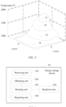
- FIG. 5 The schematic diagram of the temperature field model is a three-dimensional diagram.
- a z-axis is a temperature coordinate axis in a unit of degree Celsius (°C).
- An x-axis and a y-axis are spatial position coordinate axes (specific coordinate values are not shown in the figure).
- a temperature layer 51 is an abnormal temperature.
- Temperature layers 52 to 53 are diffusion temperatures generated by the temperature field model.
- the temperature field model may determine a temperature layer at a corresponding position based on the relative positions of the second battery area and the first battery area.
- the temperature field model may further determine one abnormal increment based on the diffusion temperature and a temperature of the second battery area in a normal case. When a difference between the adjacent temperature signal and the temperature in the normal case is greater than the abnormal increment, the battery monitoring unit derates or shuts down the battery module.
- the battery monitoring unit reports fault information.
- the fault information indicates that a temperature sensor corresponding to the abnormal temperature signal is faulty.
- the battery monitoring unit may determine that an actual temperature of the first battery area does not reach the first preset temperature threshold, and the abnormal temperature signal is an incorrect temperature signal, in other words, the temperature sensor in the first battery area is faulty.
- the battery monitoring unit may report the fault information indicating that the temperature sensor is faulty.
- the battery monitoring unit determines the first battery area corresponding to the abnormal temperature signal that reaches the first preset temperature threshold.
- the adjacent temperature signal of the second battery area that is connected to the first battery area is greater than the second preset temperature threshold, the rated power of the battery module is reduced. In this way, the battery module is not incorrectly protected because a temperature sensor is faulty. This improves precision and stability of the energy storage system.
- FIG. 6 is a schematic diagram of an embodiment of an energy storage device according to an embodiment of this application.
- the energy storage device 60 includes the following units.
- a receiving unit 601 is configured to receive a plurality of temperature signals. Each of the plurality of temperature signals comes from temperature sensors in different battery areas.
- the battery area is disposed in a battery module. Each battery area includes at least one battery.
- An obtaining unit 602 is configured to: when there is an abnormal temperature signal that reaches a first preset temperature threshold in the plurality of temperature signals, obtain a plurality of adjacent temperature signals.
- the adjacent temperature signal is a temperature signal corresponding to a second battery area that is connected to a first battery area corresponding to the abnormal temperature signal. There are one or more second battery areas.
- a derating unit 603 is configured to: when the adjacent temperature signal is greater than a second preset temperature threshold, reduce rated power of the battery module.
- the energy storage device 60 further includes a reporting unit 604.
- the reporting unit 604 is specifically configured to: when the adjacent temperature signal is less than the second preset temperature threshold, report fault information, where the fault information indicates that a temperature sensor corresponding to the abnormal temperature signal is faulty.
- the obtaining unit 602 is specifically configured to: determine the first battery area corresponding to the abnormal temperature signal; determine the second battery area that is connected to the first battery area; and obtain the adjacent temperature signal based on a temperature sensor corresponding to the second battery area.
- the energy storage device 60 further includes a shutdown unit 605.
- the shutdown unit 605 is specifically configured to: when there is still a temperature signal that reaches the first preset temperature threshold in the plurality of temperature signals of the battery module whose rated power is reduced, shut down the battery module whose rated power is reduced.
- the second preset temperature threshold is obtained by performing simulation by the battery monitoring unit based on the abnormal temperature signal.
- a temperature field model is disposed in the battery area.
- the temperature field model is used for simulation based on the abnormal temperature signal to obtain the second preset temperature threshold.
- the temperature field model is a simulation model including temperature gradients that are formed based on temperature diffusion. The temperature gradients are gradients distinguished by temperatures.
- the plurality of battery areas are equally sized areas.
- the energy storage device 60 may perform operations performed by the battery monitoring unit in the embodiment shown in FIG. 3 . Details are not described herein again.
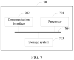
- FIG. 7 is a schematic diagram of a possible logical structure of a computer device 70 according to an embodiment of this application.
- the computer device 70 includes a processor 701, a communication interface 702, a storage system 703, and a bus 704.
- the processor 701, the communication interface 702, and the storage system 703 are connected to each other through the bus 704.
- the processor 701 is configured to control and manage an action of the computer device 70.
- the processor 701 is configured to perform steps performed by the battery monitoring unit in FIG. 3 .
- the communication interface 702 is configured to support the computer device 70 to perform communication.
- the storage system 703 is configured to store program code and data of the computer device 70.
- the processor 701 may be a central processing unit, a general-purpose processor, a digital signal processor, an application-specific integrated circuit, a field programmable gate array or another programmable logical device, a transistor logical device, a hardware component, or any combination thereof.
- the processor may implement or execute various example logical blocks, modules, and circuits described with reference to content disclosed in this application.
- the processor 701 may be a combination implementing a computing function, for example, a combination of one or more microprocessors or a combination of a digital signal processor and a microprocessor.
- the bus 704 may be a peripheral component interconnect (Peripheral Component Interconnect, PCI) bus, an extended industry standard architecture (Extended Industry Standard Architecture, EISA) bus, or the like. Buses may be classified into an address bus, a data bus, a control bus, and the like. For ease of representation, only one bold line is used for representation in FIG. 7 , but this does not mean that there is only one bus or only one type
- the receiving unit 601 and the reporting unit 604 in the energy storage device 60 are equivalent to the communication interface 702 in the computer device 70.
- the obtaining unit 602, the derating unit 603, and the shutdown unit 605 in the energy storage device 60 may be equivalent to the processor 701.
- the computer device 70 in this embodiment may correspond to the battery monitoring unit in FIG. 3 .
- the processor 701 and the communication interface 702 in the computer device 70 may implement functions and/or various steps performed by the battery monitoring unit in FIG. 3 . For brevity, details are not described herein again.
- a computer-readable storage medium stores computer-executable instructions.
- the device executes the computer-executable instructions, the device performs the steps of the battery monitoring method performed by the battery monitoring unit in FIG. 3 .
- a computer program product is further provided.
- the computer program product includes computer-executable instructions, and the computer-executable instructions are stored in a computer-readable storage medium.
- a processor of a device executes the computer-executable instructions, the device performs the steps of the battery monitoring method performed by the battery monitoring unit in FIG. 3 .
- the disclosed system, apparatus, and method may be implemented in other manners.
- the described apparatus embodiment is merely an example.
- division into the units is merely logical function division and may be other division in actual implementation.
- a plurality of units or components may be combined or integrated into another system, or some features may be ignored or not performed.
- the displayed or discussed mutual couplings or direct couplings or communication connections may be implemented by using some interfaces.
- the indirect couplings or communication connections between the apparatuses or units may be implemented in electronic, mechanical, or other forms.
- the units described as separate parts may or may not be physically separate, and parts displayed as units may or may not be physical units, may be located in one position, or may be distributed on a plurality of network units. Some or all of the units may be selected based on actual requirements to achieve the objectives of the solutions of embodiments.
- functional units in embodiments of this application may be integrated into one processing unit, each of the units may exist alone physically, or two or more units are integrated into one unit.
- the integrated unit may be implemented in a form of hardware, or may be implemented in a form of a software functional unit.
- the integrated unit When the integrated unit is implemented in the form of the software functional unit and sold or used as an independent product, the integrated unit may be stored in a computer-readable storage medium. Based on such an understanding, the technical solutions of this application essentially, or the part contributing to the conventional technology, or all or some of the technical solutions may be implemented in the form of a software product.
- the computer software product is stored in a storage medium and includes several instructions for instructing a computer device (which may be a personal computer, a server, or a network device) to perform all or some of the steps of the methods described in embodiments of this application.
- the foregoing storage medium includes any medium that can store program code, such as a USB flash drive, a removable hard disk, a read-only memory (ROM, read-only memory), a random access memory (RAM, random access memory), a magnetic disk, or an optical disc.
- program code such as a USB flash drive, a removable hard disk, a read-only memory (ROM, read-only memory), a random access memory (RAM, random access memory), a magnetic disk, or an optical disc.
Landscapes
- Engineering & Computer Science (AREA)
- Manufacturing & Machinery (AREA)
- Chemical & Material Sciences (AREA)
- Chemical Kinetics & Catalysis (AREA)
- Electrochemistry (AREA)
- General Chemical & Material Sciences (AREA)
- General Physics & Mathematics (AREA)
- Physics & Mathematics (AREA)
- Algebra (AREA)
- Mathematical Analysis (AREA)
- Mathematical Optimization (AREA)
- Pure & Applied Mathematics (AREA)
- Microelectronics & Electronic Packaging (AREA)
- Secondary Cells (AREA)
- Charge And Discharge Circuits For Batteries Or The Like (AREA)
Applications Claiming Priority (1)
| Application Number | Priority Date | Filing Date | Title |
|---|---|---|---|
| PCT/CN2021/082526 WO2022198469A1 (zh) | 2021-03-24 | 2021-03-24 | 储能系统、电池监控方法以及储能设备 |
Publications (2)
| Publication Number | Publication Date |
|---|---|
| EP4303984A1 true EP4303984A1 (de) | 2024-01-10 |
| EP4303984A4 EP4303984A4 (de) | 2024-05-15 |
Family
ID=83395020
Family Applications (1)
| Application Number | Title | Priority Date | Filing Date |
|---|---|---|---|
| EP21932098.3A Pending EP4303984A4 (de) | 2021-03-24 | 2021-03-24 | Energiespeichersystem, batterieüberwachungsverfahren und energiespeichervorrichtung |
Country Status (5)
| Country | Link |
|---|---|
| US (1) | US20240014459A1 (de) |
| EP (1) | EP4303984A4 (de) |
| CN (1) | CN116783758A (de) |
| AU (1) | AU2021435460A1 (de) |
| WO (1) | WO2022198469A1 (de) |
Families Citing this family (3)
| Publication number | Priority date | Publication date | Assignee | Title |
|---|---|---|---|---|
| CN115420401A (zh) * | 2022-08-25 | 2022-12-02 | 上海玫克生储能科技有限公司 | 一种预警方法、预警系统、存储介质及电子设备 |
| CN116111677B (zh) * | 2023-01-03 | 2023-08-29 | 法罗电力(浙江)有限公司 | 一种应用于储能领域的后台监控数据处理方法与系统 |
| CN117352913B (zh) * | 2023-12-05 | 2024-04-19 | 承德神奥新能源科技有限公司 | 一种电池包的管理方法及系统 |
Family Cites Families (8)
| Publication number | Priority date | Publication date | Assignee | Title |
|---|---|---|---|---|
| KR20150102778A (ko) * | 2013-11-13 | 2015-09-08 | 삼성에스디아이 주식회사 | 배터리 팩, 배터리 팩을 포함하는 장치, 및 배터리 팩의 관리 방법 |
| CN106450530A (zh) * | 2016-12-15 | 2017-02-22 | 北京新能源汽车股份有限公司 | 一种电池模组测试系统及方法 |
| GB2566308B (en) * | 2017-09-08 | 2020-05-20 | Hyperdrive Innovation Ltd | Battery management system |
| DE102018217680A1 (de) * | 2018-10-16 | 2020-04-16 | Robert Bosch Gmbh | Verfahren und Vorrichtung zum Ermitteln einer Betriebsbereitschaft einer aus mehreren Modulen zusammengesetzten Batterie eines elektrisch angetriebenen Fortbewegungsmittels |
| CN109795323A (zh) * | 2019-02-18 | 2019-05-24 | 奇瑞汽车股份有限公司 | 一种电动汽车的电池包的保护方法及装置 |
| CN110068768A (zh) * | 2019-04-30 | 2019-07-30 | 北京长城华冠汽车科技股份有限公司 | 电池热失控检测方法及装置 |
| CN211045641U (zh) * | 2019-11-07 | 2020-07-17 | 安徽锐能科技有限公司 | 温度采集单元及电池管理系统 |
| CN111439127A (zh) * | 2019-12-31 | 2020-07-24 | 蜂巢能源科技有限公司 | 车辆、电池包的故障检测方法和装置 |
-
2021
- 2021-03-24 WO PCT/CN2021/082526 patent/WO2022198469A1/zh not_active Ceased
- 2021-03-24 EP EP21932098.3A patent/EP4303984A4/de active Pending
- 2021-03-24 AU AU2021435460A patent/AU2021435460A1/en active Pending
- 2021-03-24 CN CN202180088905.7A patent/CN116783758A/zh active Pending
-
2023
- 2023-09-19 US US18/469,802 patent/US20240014459A1/en active Pending
Also Published As
| Publication number | Publication date |
|---|---|
| WO2022198469A1 (zh) | 2022-09-29 |
| CN116783758A (zh) | 2023-09-19 |
| US20240014459A1 (en) | 2024-01-11 |
| EP4303984A4 (de) | 2024-05-15 |
| AU2021435460A1 (en) | 2023-11-09 |
Similar Documents
| Publication | Publication Date | Title |
|---|---|---|
| US20240014459A1 (en) | Energy storage system, battery monitoring method, and energy storage device | |
| US11408942B2 (en) | Method for predicting service life of retired power battery | |
| CA2787867C (en) | Short detection in battery cells | |
| KR102947181B1 (ko) | 배터리 셀의 내부 이상을 진단하는 방법 및 이를 적용한 배터리 팩 | |
| WO2023193388A1 (zh) | 一种存储系统供电过程中的故障定位方法、装置以及介质 | |
| US20230258735A1 (en) | Battery Diagnosing Apparatus and Method | |
| US9933488B2 (en) | Open circuit voltage checking for a battery system | |
| WO2017203265A1 (en) | Methods and apparatus for energy storage | |
| US20250201942A1 (en) | Battery pack, detection method thereof, and battery management system | |
| US11733304B2 (en) | Determination apparatus | |
| CN111830394A (zh) | 充电电路故障检测方法、电子设备及计算机可读存储介质 | |
| WO2023050172A1 (zh) | 一种防止电池过充方法、装置,充电机及存储介质 | |
| CN110492557B (zh) | 一种电池的故障处理方法及设备 | |
| CN116430252A (zh) | 电池包内短路的检测方法、充电设备及可读存储介质 | |
| CN118539565B (zh) | 电池充电管理方法、装置、电子设备及存储介质 | |
| EP4560875A1 (de) | Verfahren und vorrichtung zur überwachung von künstlicher intelligenz und zum schutz der batterieleistung | |
| CN119627278A (zh) | 电池簇并机控制方法、装置、储能系统、电子设备及介质 | |
| JP6819912B1 (ja) | 蓄電装置の保守方法、及び、保守プログラム | |
| US20230122667A1 (en) | Method and apparatus for monitoring battery backup unit, server, and readable storage medium | |
| CN112242731A (zh) | 用于电动汽车的过流保护装置、电池系统及电动汽车 | |
| AU2024330648A1 (en) | System for reducing battery cell failure propagation risk of a rechargeable battery | |
| CN117650600A (zh) | 一种储能电池补电方法、装置、设备及介质 | |
| CN109459706B (zh) | 电池检测方法和装置 | |
| KR102688743B1 (ko) | 분산 배터리의 soh에 기초하여 이상을 탐지하는 방법 | |
| KR102899567B1 (ko) | 배터리 관리 장치 및 그것의 동작 방법 |
Legal Events
| Date | Code | Title | Description |
|---|---|---|---|
| STAA | Information on the status of an ep patent application or granted ep patent |
Free format text: STATUS: THE INTERNATIONAL PUBLICATION HAS BEEN MADE |
|
| PUAI | Public reference made under article 153(3) epc to a published international application that has entered the european phase |
Free format text: ORIGINAL CODE: 0009012 |
|
| STAA | Information on the status of an ep patent application or granted ep patent |
Free format text: STATUS: REQUEST FOR EXAMINATION WAS MADE |
|
| 17P | Request for examination filed |
Effective date: 20231002 |
|
| AK | Designated contracting states |
Kind code of ref document: A1 Designated state(s): AL AT BE BG CH CY CZ DE DK EE ES FI FR GB GR HR HU IE IS IT LI LT LU LV MC MK MT NL NO PL PT RO RS SE SI SK SM TR |
|
| A4 | Supplementary search report drawn up and despatched |
Effective date: 20240416 |
|
| RIC1 | Information provided on ipc code assigned before grant |
Ipc: H01M 50/581 20210101ALN20240410BHEP Ipc: H01M 50/204 20210101ALN20240410BHEP Ipc: H01M 10/42 20060101ALI20240410BHEP Ipc: H01M 10/48 20060101AFI20240410BHEP |
|
| DAV | Request for validation of the european patent (deleted) | ||
| DAX | Request for extension of the european patent (deleted) | ||
| GRAP | Despatch of communication of intention to grant a patent |
Free format text: ORIGINAL CODE: EPIDOSNIGR1 |
|
| STAA | Information on the status of an ep patent application or granted ep patent |
Free format text: STATUS: GRANT OF PATENT IS INTENDED |
|
| GRAJ | Information related to disapproval of communication of intention to grant by the applicant or resumption of examination proceedings by the epo deleted |
Free format text: ORIGINAL CODE: EPIDOSDIGR1 |
|
| STAA | Information on the status of an ep patent application or granted ep patent |
Free format text: STATUS: REQUEST FOR EXAMINATION WAS MADE |
|
| GRAP | Despatch of communication of intention to grant a patent |
Free format text: ORIGINAL CODE: EPIDOSNIGR1 |
|
| STAA | Information on the status of an ep patent application or granted ep patent |
Free format text: STATUS: GRANT OF PATENT IS INTENDED |
|
| INTG | Intention to grant announced |
Effective date: 20260102 |
|
| P01 | Opt-out of the competence of the unified patent court (upc) registered |
Free format text: CASE NUMBER: UPC_APP_0003579_4303984/2026 Effective date: 20260202 |
|
| GRAS | Grant fee paid |
Free format text: ORIGINAL CODE: EPIDOSNIGR3 |
|
| GRAA | (expected) grant |
Free format text: ORIGINAL CODE: 0009210 |
|
| STAA | Information on the status of an ep patent application or granted ep patent |
Free format text: STATUS: THE PATENT HAS BEEN GRANTED |